

Page 1
BOOK# 091-39-2
REV C: 2-07-03
INSTRUCTION MANUAL
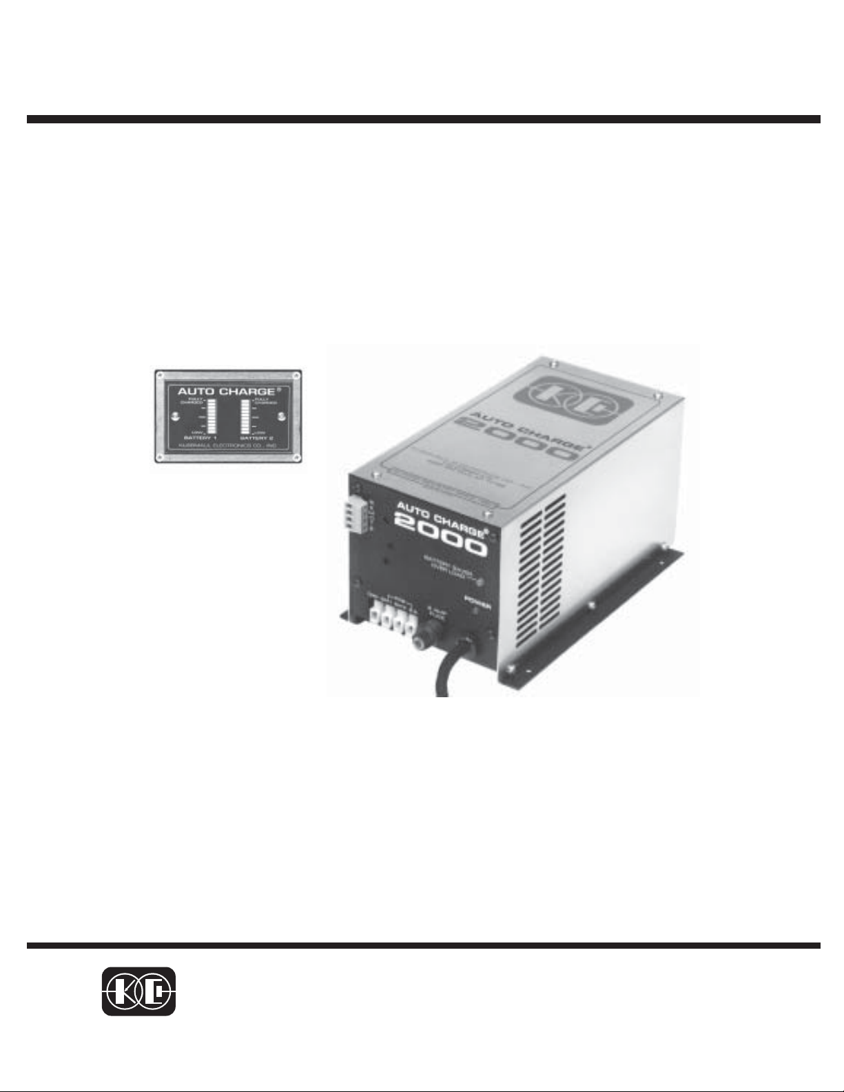
AUTO CHARGE
2000
AUTOMATIC BATTERY CHARGER
MODEL #091-39-12
NOTE :
This charger is designed for
vehicles with dual batteries
and negative ground.
INPUT :115 volt, 50/60 Hz, 3.5 amps
OUTPUT: 18 AMPERES
3 YEAR WARRANTY
KUSSMAUL ELECTRONICS CO., INC.
170 CHERRY AVE., WEST SAYVILLE, N.Y. 11796
TEL: in NY 631-567-0314 TOLL FREE: 800-346-0857 FAX: 631-567-5826
Page 2

INTRODUCTION
The AUTO CHARGE 2000 is a compact, completely automatic, dual channel
battery charger designed for vehicles with two batteries. The charger is ruggedized to withstand the shock and vibration encountered by vehicle mounted
equipment.
The battery charger features:
• Independent charge controls for each battery
• Electronic remote sensing of true battery voltages, eliminates the need
for sensing wires
• Automatic current limiting and apportionment
• Built-in BATTERY SAVER
• Remote dual battery charge/condition indicator
• Power “ON” LED indicator
• BATTERY SAVER overload indicator
DESCRIPTION
Independent Charge Controls & Electronic Remote Sensing
The charger contains two independent charge controls, one for each battery.
This allows each battery to be independently charged while maintaining battery
isolation. Each battery voltage is remotely sensed, electronically, eliminating the
need for four sense wires. Each of the charge controls is completely automatic and
stops charging the battery when it is fully charged. There is no trickle charge and
therefore no danger of overcharging and water boil-off.
Automatic Current Limiting & Apportionment
The charger contains automatic current limiting at 15 amperes. This is a total
current limit for the two batteries combined. The charger automatically apportions
the current to each battery. Either battery can draw the total 15 amperes. When
charging unequally charged batteries, the lower charged battery receives a higher
charge rate. When the batteries are equal, the current is shared equally until they
are fully charged at which time the current goes to zero.
Page 3

Battery Saver & Indicator
A 3 ampere BATTERY SAVER is built into the charger. When connected as
shown in the installation wiring diagram, loads on battery #1 such as radios and
rechargeable hand lights are automatically switched to the BATTERY SAVER
when power is applied to the charger. The BATTERY SAVER allows more efficient
charging by removing these loads. A BATTERY SAVER overload indicator alerts
the operator that the BATTERY SAVER load has exceeded 3 amperes.
WHEN A BATTERY SAVER OVERLOAD OCCURS:
a. Remove the loads for approximately two minutes
b. Reduce the load to 3 amperes or less
c. Reapply the load to the BATTERY SAVER
No fuses are required or provided as the BATTERY SAVER contains an electronic
overload interrupter.
Remote Dual Battery Charge Condition Indicator
This remote indicator shows the charge condition of each battery in 10 levels
from “LOW CHARGE” to “FULLY CHARGED”. This device indicates a defective
battery when a bar graph does not rise to the “FULLY CHARGED” level after an
extended period of charging.
NOTE: If a battery is being charged with an external load of 1.5 to 4 amperes
across it’s terminals, the bar graph may move down 1 or 2 levels. This
does not indicate a defective battery.
To avoid this, connect all external loads to the BATTERY SAVER
terminals.
Loads connected to the BATTERY SAVER will be powered either from
the BATTERY SAVER power supply when the A.C. power is “ON”, or
they will be connected to battery #1 when the A.C. power is “OFF”.
Page 4

Installation Wiring Diagram
AUTO CHARGE
2000
Battery Saver Loads (3 amps max.).
When the charger is disconnect from 120
volts AC the Battery Saver loads automatically are connected to battery #1.
CAUTION BATTERY SAVER
This battery saver output is a full wave rectified sine wave. The 12.5 volts D.C. has a peak value of approximately
17.5 volts.
It is recommended that the loads are not highly capacitive. A large capacitor on the load terminal will “peak
detect” the output and create a voltage of approximately 17 volts. This voltage may be too high for the component
connected.
It is suggested that the installer check the output of the battery saver (when operating with A.C. Input) and
determine as each load is connected that the voltage does not rise. Any load that creates an increase in voltage
should not be connected to the battery saver but rather be connected directly to the battery.
WIRE SIZE CHART
CONNECTION ITEM DEFINITION WIRE SIZE
COM
BAT 1
BAT 2
BATTERY
COMMON
BATTERY#1POSITIVE CHARGING LEAD
BATTERY#2POSITIVE CHARGING LEAD
NEGATIVE CHARGING LEAD
FOR CHARGING BATTERIES
AND BATTE RY SAV ER LOA D
FOR BATTERY # 1
FOR BATTERY # 2
14 AWG
14 AWG
14 AWG
IMPORTANT : Wire size is
for a maximum length of 10
feet. If wiring is to be longer,
larger wiring is required.
Additional information is
available on request.
B.S.
BATTERY
SAVER
POSITIVE LEAD FOR BATTERY
SAVER LOADS.
16 AWG
Page 5

Specifications:
Input: 120 volt, 50/60 Hz, 3.5 amperes
Input Fuse: 6 ampere, fast acting
Output: 12 volts D.C. 15 amperes Max., total both outputs
Remote Sensing: Electronic, sense wires not required
Number of Charger Outputs: 2
Number of Battery Saver Outputs: 1
Battery Saver Output: 12 volts D.C., 3 amperes Max.
Indicators: Power: Red LED, indicates 120 volts power applied
Battery Saver Overload: Yellow LED, indicates Battery Saver
load greater than 3 amperes
Dual Bar Graph: indicates charger output to two batteries and
state of charge of batteries
Weight: 16 lbs
Outline Dimensions, AUTO CHARGE 2000
Page 6

INSTALLATION RECORD & WARRANTY
Date Installed
Installed By
Vehicle Identification
Vehicle Owner
WARRANTY
All product of Kussmaul Electronics Company Inc. are warranted to
be free of defects of material or workmanship. Liability is limited to repairing or replacing at our factory, without charge, any material or defects
which become apparent in normal use within 3 years from the date the
equipment was shipped.
Kussmaul Electronics Company, Inc. shall have no liability for damages of any kind to associated equipment arising from the installation and
/or use of the Kussmaul Electronics Company, Inc. products. The purchaser, by the acceptance of the equipment, assumes all liability for any
damages which may result from its installation, use or misuse, by the
purchaser, his or its
Page 7

INDICATOR INSTALLATION
1. Locate Indicator in a convenient place on the vehicle.
2. Place the template in position and center punch in 3 places.
3. Drill holes as shown.
5. Connect wiring to charger using butt connector supplied.
6. Install as shown.
7. Insert 2 #6-32 screws and tighten, (CAUTION Do not over tighten because
you will bend the plastic bezel and brake the watertight seal).
(2)
(2)
LOCK & FLAT WASHER
5/32" DIA.
7/8" DIA.
HOLE TEMPLATE
Page 8

INDICATOR INSTALLATION
1. Locate Indicator in a convenient place on the vehicle.
2. Place the template in position and center punch in 4 places.
3. Drill holes as shown.
5. Cut out square hole.
6. Connect wiring to charger using butt connector supplied.
7. Install as shown.
8. Insert 4 #6-32 screws and tighten, (CAUTION Do not over tighten because
you will bend the plastic bezel and brake the watertight seal).
HOLE TEMPLATE
 Loading...