

BOOK# 091-66
file: 091-66-12-REVB
REV B: 2-7-03
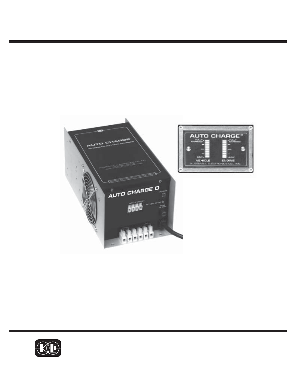
INSTRUCTION MANUAL
AUTO CHARGE D
AUTOMATIC DUAL OUTPUT
BATTERY CHARGER
Designed expressly for vehicles with DDEC ENGINES
MODEL #091-66-12
INPUT :120 volt, 50/60 Hz, 8 amps
OUTPUT VEHICLE BATTERY: 25 AMPERES
OUTPUT ENGINE BATTERY: 3 AMPERES
OUTPUT BATTERY SAVER : 5 AMPERES
3 YEAR WARRANTY
KUSSMAUL ELECTRONICS CO., INC.
170 CHERRY AVE., WEST SAYVILLE, N.Y. 11796
TEL: in NY 631-567-0314 TOLL FREE: 800-346-0857 FAX: 631-567-5826

INTRODUCTION
The Auto Charge D is a dual battery system automatic battery charger designed
specifically for vehicles with a DDEC control and a separate engine battery.
The engine battery on DDEC equipped vehicles presents a unique problem.
While it is desirable to have a charger to maintain this battery in a fully charged
condition, this battery is relatively lightly loaded. It is never required to operate
any of the vehicle mounted accessories and is rarely discharged. The vehicle,
however, may have multiple batteries which may be heavily loaded and require
considerable charging. The unequal loading may cause either overcharging the
engine battery or poor charger capacity utilization. The Auto Charge D specifically addresses this problem and automatically recharges and maintains both
vehicle and engine batteries.
The battery charger features are:
• Independent charge controls for each battery
• Electronic remote sensing of true battery voltages,eliminates the need
for sensing wires
• Automatic current limiting for both engine and vehicle batteries
• Built-in 5 ampere BATTERY SAVER
• Remote dual battery charge/condition indicator
• Power “ON” LED indicator
• BATTERY SAVER overload indicator
DESCRIPTION
Independent Charge Controls & Electronic Remote Sensing
The charger contains two independent charge controls, one for each battery.
This allows each battery to be independently charged while maintaining battery
isolation. Each battery voltage is remotely sensed, electronically, eliminating
the need for four sense wires. Each of the charge controls is completely automatic and stops charging the battery when it is fully charged. There is no
trickle charge and therefore no danger of overcharging and water boil-off.

Automatic Current Limiting
The charger contains automatic current limiting for each output. The vehicle
output is limited at 25 amperes while the engine output is limited at 3 amperes.
This provides the higher current to the larger batteries where it is needed.
BATTERY SAVER & INDICATOR
A 5 ampere BATTERY SAVER is built into the charger. When connected as
shown in the installation wiring diagram, loads on the vehicle battery such as
radios and rechargeable hand lights are automatically switched to the BATTERY SAVER when power is applied to the charger. The BATTERY SAVER
allows more efficient charging by removing these loads. A BATTERY SAVER
overload indicator alerts the operator that the BATTERY SAVER load has exceeded 5 amperes.
WHEN A BATTERY SAVER OVERLOAD OCCURS THE BATTERY SAVER
OUTPUT IS INTERRUPTED BY AN AUTOMATIC THERMAL CIRCUIT
BREAKER. THIS CIRCUIT BREAKER WILL CONTINUALLY CYCLE THE
OUTPUT ìONî AND ìOFFî UNTIL THE OVERLOAD IS REMOVED.
WHENEVER THE BATTERY SAVER OUTPUT IS ìOFFî THE
OVERLOAD INDICATOR IS LIT.
Remote Dual Battery Charge Condition Indicator
This remote indicator shows the charge condition of each battery in 10 levels
for “LOW CHARGE” to “FULLY CHARGED”. This device indicates a defective
battery when a bar graph does not rise to the “FULLY CHARGED” level after an
extended period of charging.
NOTE: If a battery is being charged with an external load of 1.5 to 5 amperes
across its terminals, the bar graph may move down 1 or 2 levels. This
does not indicate a defective battery. To avoid this, connect all external
loads to the BATTERY SAVER terminals
Loads connected to the BATTERY SAVER will be powered either from the
BATTERY SAVER power supply when the A.C. power is “ON” or they will
be connected to the vehicle battery when the A.C. power is “OFF”.

Remote
A
Ind ica tor
INSTALLATION WIRING DIAGRAM
AUTO CHARGE D
REMOTE DISPLAY
ENGINE
COM
BATTERY
POSITIVE
VEHICLE
BATTERY
BATTERY SAVER
OVER LOAD
BATTERY
SA VE R
POWER
FUSE
Chassis
Ground
EngineEngine
Engine
EngineEngine
BatteryBattery
Battery
BatteryBattery
VehicleVehicle
Vehicle
VehicleVehicle
BatteryBattery
Battery
BatteryBattery
WIRE SIZE CHART
CONNECTION DEFINITION WIRE SIZE
COM
ENGINE BATTERY
VEHICLE BATTERY
BATTERY SAVER
NEGATIVE CHARGING LEAD
POSITIVE CHAR GING LEAD ENGI NE BATTERY
POSITIVE CHARGING LEAD VEHICLE BATTERY
POSITIVE OUTPUT
Chassis
Ground
Chassis
Ground
8 AWG
14 AWG
10 AWG
14 AWG
+
1
2
V
o
l
t
s
Battery Saver Loads
(5 amps max.).
When the charger
is disconnected from
120 volts AC the
Battery Saver loads
are automatically
connected to vehicle
battery.
ccessories
IMPORTANT : Wire size is
for a maximum length of 10
feet. If wiring is to be longer,
larger wiring is required.
Additional information is
available on request.

INDICATOR INSTALLATION
1. Locate Indicator in a convenient place on the vehicle.
2. Place the template in position and center punch in 4 places.
3. Drill holes as shown.
5. Cut out square hole.
6. Connect wiring to charger using butt connector supplied.
7. Install as shown.
8. Insert 4 #6-32 screws and tighten, (CAUTION Do not over tighten because
you will bend the plastic bezel and brake the watertight seal).
HOLE TEMPLATE

SPECIFICATIONS:
Input: 120 volt, 50/60 Hz, 8 amperes
Input Fuse: 12 ampere, fast blow
Output - Vehicle: 25 amperes Max.
Output - Engine: 3 amperes Max.
Output - Battery Saver: 5 amperes Max.
Indicators:
Power: Red LED, indicates 120 volt power applied
Battery Saver Overload: Yellow LED, flashing, indicates BAT
TERY SAVER load greater than 5 amperes
Dual Bar Graph: indicates charger output to two batteries and state
of charge of batteries
Weight: 21 pounds
Outline Dimensions, AUTO CHARGE D

INSTALLATION RECORD & WARRANTY
Date Installed
Installed By
Vehicle Identification
Vehicle Owner
WARRANTY
All products of Kussmaul Electronics Company Inc. are warranted to be
free of defects of material or workmanship. Liability is limited to repairing or
replacing at our factory, without charge, any material or defects which
become apparent in normal use within 3 years from the date the equipment
was shipped. Equipment is to be returned, shipping charges prepaid and will
be returned, after repair, shipping charges paid.
Kussmaul Electronics Company, Inc. shall have no liability for damages
of any kind to associated equipment arising from the installation and /or use
of the Kussmaul Electronics Company, Inc. products. The purchaser, by the
acceptance of the equipment, assumes all liability for any damages which
may result from its installation, use or misuse, by the purchaser, his or its
employees or others.
 Loading...