


Operating Instruction and
Parts Manual for
KPT 36/48
Walk Behind
Power Trowel
12010 Dairy Ashford Road, Suite 160
Sugar Land, TX 77478
281-313-2506 • 800-469-4178

TABLE OF CONTENTS
2
Contents ……………………………………………...…1
Forward …………………………………………...…… 2
Feature…………………………….......................………2
Specification ………………………….................………2
Safety precautions …………………………………...… 3
Maintenance record ……… ……………………....……4
Maintenance schedule…………................................……5
Operation elements………................................…………7
Operation (floating)…………………..........................…8
Operation (finishing)…………………………............…8
Starting & stopping procedure…………………………9
1. Before operation checks…………………………...…9
2. Starting engine
procedure……………………………9
3. Stopping engine
procedure……………………….…11
4. Setting engine speed………………………...………12
Lubrication………………………………………….…12
1. Engine oil lever check………………………………12
2. Engine oil change……………………………………13
Spark plugs…………………………………………….13
Carburetor adjustment……………………………..…14
Air filter service………………………………………..15
Storage…………………………………………………16
Troubleshooting…………………………………….…16
FOREWARD
• For your own safety and protection from bodily injuries,
carefully read, understand and follow the safety instructions
in this manual.
• Please operate and maintain your machine in accordance
with the instructions in this manual.
• Defective machine parts are to be replaced as soon as
possible.
• Keep this owner's manual handy, so you can refer to it at
any time.
• No part of this publication may be reproduced without
written permission.
• We expressly reserve the right to technical modifications-
even without express due notice - which aim at improving
our machines or their safety standards.
FEATURE
The KPT 36 and the KPT 48 Walk Behind Power Trowels can
be used in surface finishing of concrete road, terrace, boatyard,
airport and floor etc.
Deadman switch design pr ovide safe. A sophisticated system to
protect the operator from an out-of-control spinning handle.
When the operator is using a walk-behind power trowel and
let go of the safety sensor detects the motion of the handle and
stops the engine before the handle reaches a 45-degree ro tation.
The handle can be adjusted due to the stature of operator, and it
offers maximum control and comfort for the operation. The alloy
blades which have get heat treatment are worn well. Low center
of gravity provides workers with saf e and stable operation.
KPT 36
Weight: 83kg
Diameter: 980mm
Float pan diameter: 945mm
Trowel blade rev: 70r/min~140r/min
Overall diameter: 1820×945×980mm
Blades: 4
Gearbox oil: WA460
Gearbox oil capacity: 950ml
Power output: 5.5hp
Engine type: HONDA GX160
Fuel capacity (L): 3.6
Engine oil type: Recommended
SAE10W-30
Engine oil capacity (L): 0.6
SPECIFICATION
KPT 48
Weight: 119kg
Diameter: 1175mm
Float pan diameter: 1180mm
Trowel blade rev: 70r/min~140r/min
Overall diameter: 2080×1170×1020mm
Blades: 4
Gearbox oil: WA460
Gearbox oil capacity: 950ml
Power output: 9/13hp
Engine type: HONDA GX270/390
Fuel capacity (L): 6/6.5
Engine oil type: Recommended SAE10W30
Engine oil capacity (L): 1.1

SAFETY PRECAUTIONS
3
1. Before starting operation, the operator has to check that all control and safety devices function properly.
2. Always keep unauthorized, inexperienced, untrained people away from this machine.
3. Rotating and moving parts will cause injury if contacted. Make sure guards are in place. Keep hands and feet away
from moving parts.
4. The engine must always be stopped before attempting any repair or adjustments. Ignition switch should be off.
5. To avoid slipping and loss of control when starting the trowel, the operator should maintain good footing. It is
recommended that the operator wear safety shoes for added protection.
6. Be careful when working around pipes or ducts protruding from the floor or slab edges. If the trowel blades hit such
obstacles, damage to the machine or possible operator injury may result.
7. When starting the machine, do not exceed 1/3 throttle position. A higher setting may cause the Centrifugal clutch to
engage and the handle to rotate.
8. Be careful not to come in contact with the muffler when the engine is hot, serious burns may result!
9. Over time, the blades will form a sharp edge. Be careful when handling the old blades.
10. Gasoline is extremely flammable, and gasoline vapor can explode. Refuel outdoors, in a well-ventilated area, and keep
other flames and sparks away.
11. Do not fill the fuel tank completely. After refueling, tighten the fuel tank cap securely.
12. Before beginning your preoperational checks, be sure the engine is level and the engine switch is in the OFF. The max.
gradient of 20° must not be exceeded when the engine working.
13. Don’t allow children to operate the engine. Keep children and pets away from the area of operation.
14. After each use your machine should be cleaned to remove any dust and debris from the undercarriage and
surrounding components.
15. When the machine start working you should be check the clutch whether or not wear and tear. If the clutch will have
3/4 worn and torn, you must change new clutch-ring.
16. Check that all shields and covers are in place, and all nuts, bolts, and screw are tightened when the machine working.
Make sure put the cable while the machine working.
MAINTENANCE RECORD
Due to the nature and environment of use, Walk-behind Power Trowels could be exposed to severe operating
conditions. Some general maintenance guidelines will extend the useful life of your trowel.
1. The initial service for your trowel should be performed after 25 hours of use, at which time your mechanic
(or authorized repair shop) should complete all of the recommended checks in the schedule below. The chart is handy
for keeping a record of the maintenance performed and the parts used for servicing your trowel.
2. Regular service according to the schedule below will prolong the life of the Walk-behind Power Trowel and prevent
expensive repairs.
3. Keeping your Walk-behind Power Trowel clean and free from debris is the single most important regular maintenance
operation, over and above the checks in the service schedule above, that can be performed. After each use your Walk
behind Power Trowel should be cleaned to remove any dust and debris from the undercarriage and surrounding
components. Use of a power washer will make clean up quick and easy, especially if a non-stick coating was applied
prior to use.
4. In the Service Schedule below, items that should be checked, replaced or adjusted are indicated by "o" in the
column. Not all Walk-behind Power Trowel models include the same features and options and as such not all service
operations may have to be performed. For ease of recording place a checkmark (√) through the "o" when the item is
complete. If an item is not required or not complete place an "×" through the "x" in the box.
CAUTIONS! Over time, if the blades will have 3/4 worn and torn, you must change new trowel blades.
appropriate

Routine
Service Intervals
Each use
After 1.5
Months
or 50 hrs
Each 3
Months
or 100 hrs
Each 6
Months
or 200 hrs
Each 9
Months
or 300 hrs
Each 12
Months
or 400 hrs
General Inspection:
Guards
Check
O O O O O
Warning
Stickers
Check
O O O O O
Test Run
Check Operation
O O O O
Controls:
Dead-Man
Switch Operation
Check O O O O O O
Pitch
Control Assembly
Check O O O O O O
Lubricate
O O O O O
Engine:
Engine oil
Check level
O O O O O O
Change
O
O
O
Engine Oil
Filter
Replace
O
O
Oil Cooler
Clean
O O O O
Cooling Fins
Clean
O O O O O
Air cleaner
Check-clean
O O O O O
Replace
O
Air Intake Line
Check O
Replace
2 yrs
Fan Belt
Check tightness
O
O
Valve Clearance
Replace
500 hrs
Check-Adjust
O O
Fuel filter
Check & Clean
O O O O
Replace
O O
Fuel Tank
Engine wiring
Clean
500hrs
Check
O
Drive Train:
Clutch/Pulley
Operation
Check O O O O O O
Spider plate assembly
Check O O O O O O
Lubricate
O O
V-Belt Check O O O O O O
Blades Check O O O O O O
Gearbox:
Gearbox oil
Check level
O O
Check O O O
Gearbox
Breathers
Check Operation
O
O O O
MAINTENANCE SCHEDULE
OPERATION ELEMENTS
V-
belt is driven gearbox by engine, and then transmit torque to trowel and the machine working. The trowels can be
4
adjusted due to the stature of operator through pitch control assembly. Dead man switch designs provide safe and
stable operation. Holding the deadman lever before start the engine, and loosening deadman lever the machine will
stop working.
OPERATION (Floating)
When the slab has set sufficiently firm that the operator’s footprint leaves a very slight depression on the surface of the
slab, it is ready for the floating operation.
Guiding the machine on the slab is very simple; a slight upward lift of the handle causes the machine to travel to the
left. Holding the handle in the neutral position, will slowly cause the machine to spin in one spot. Slight downward
pressure on the handle causes the machine to the travel to the right. Best results are obtained by covering
approximately 4” on each turn. In other words, let the machine move right or left, backwards or forwards,
approximately 4” with each revolution of the trowels. To fill a hole or cut down hump, move the unit back and forth
over the problem area.
Under normal operating conditions the machine should cover as much as 1000 sq. ft. in about 15 minutes. It is
recommended that a slight tension on the trowel control cable, (but not a definite tilt), during the floating operation
will cause the machine to operate much smoother. After the floated slab has set sufficiently, it is ready for the finishing
operation.
CAUTION!
operation is complete.
Do not let the machine stand in one spot on the soft cement. Lift from the slab when the floating
Model 350WSB & 350WSB With Stand Parts List
OPERATION (Finishing)
When starting the finishing operation, never set the trowels up over 1/4" pitch.
After the floating operation, the first thing to do is to remove the floating disc from the blades. Clean the blades, spider
plate and disc from cement paste collected during the floating operation. Increase the blade pitch up to a maximum of 1
cm for the first finishing operation and then continue to increase the pitch on the following finishing operations.
Continue the finishing passes until you obtain the desired floor finish. The time required between each finishing pass is
again dependent on the weather conditions and water content of the concrete etc. If some areas of the concrete
set/harden too fast you may apply a small amount of water using a hand brush as an aid to achieving the finish.
STARTING & STOPPING PROCEDURE
1. Before operation checks
a.
Check the oil level: Before beginning your preoperational checks, be sure the engine is level and the engine switch
is in the OFF. Remove the filler cap/dipstick and wipe it clean. Insert and remove the dipstick without screwing it
into the filler hole. Check the oil level shown on the dipstick. If the oil level is low, remove the oil filler cap, and fill to
the upper limit mark on the dipstick with recommended oil. Screw in the filler cap/dipstick securely.
SAE 10W-30 is recommended for general use. The engine is certified to operate on unleaded gasoline with a
research octane rating of 90 or higher. Unleaded gasoline produces fewer engine and spark plug deposits and
extends exhaust system life. Never use stale or contaminated gasoline or an oil/gasoline mixture. Avoid getting dirt
or water in the fuel tank.
b.
Check air filter: Remove the air cleaner cover and inspect the filter. Clean or replace dirty filter elements. Always
replace damaged filter elements. If equipped with an oil-bath air cleaner, also check the oil level.
Notice!
Running the engine with a low oil level can cause engine damage.
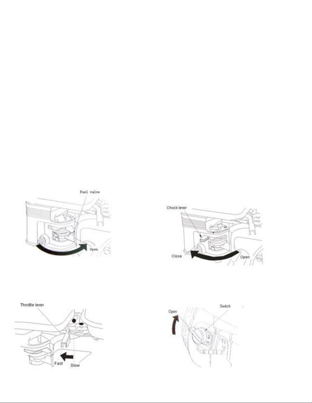
2. Start engine/Stopping engine procedure
Move the fuel valve lever to the ON position.
a.
b. Move the choke lever to the CLOSE position. If the engine is
warm or the air temperature is high, move the control lever away
from the OPEN position as soon as the engine starts.
5
c. Move the throttle lever away from the
SLOW position, about 1/3 of the way to
toward the FAST position.
d. Turn the engine switch to the ON position.
6
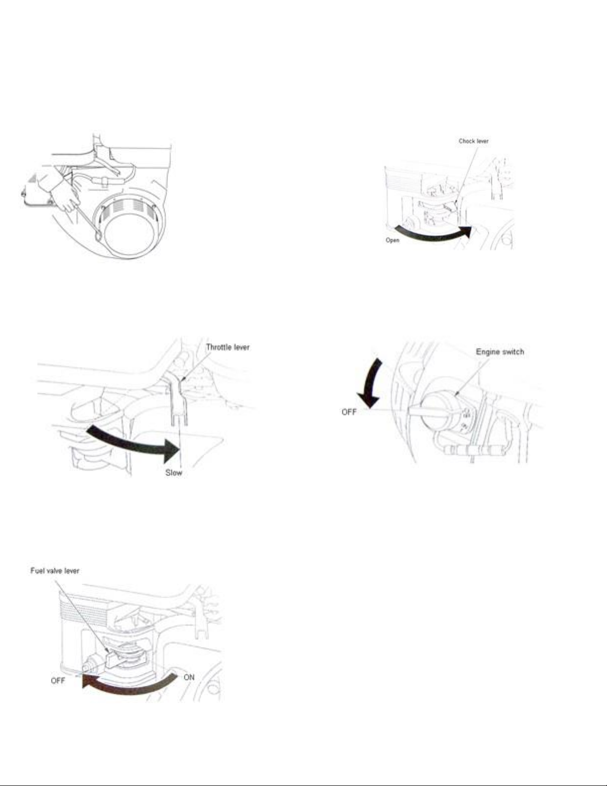
e. Pull the starter grip lightly until you feel resistance,
then pull briskly. Return the starter grip gently.
CAUTION!
Do not allow the starter grip to snap back
against the engine. Return it gently to prevent damage
to the starter.
3. Stopping the engine
a.
Move the throttle lever to the SLOW position.
f. If the chock lever or chock rod (applicable types) has been
moved to the CLOSED position to start the engine,
gradually move it to the OPEN position as the engine warms
up.
b. Turn the engine switch to the OFF position.
c. Turn the fuel valve lever to the OFF position.
4. Setting engine speed
Position the throttle lever the desired engine speed.

LUBRICATION
1. Engine oil lever check
Check the engine oil level with the engine stopped and in a level position.
1. Remove the filler cap/dipstick and wipe it clean.
2. Insert and remove the dipstick without screwing it into the filler neck.
Check the oil level shown on the dipstick.
3. If the oil level is low, fill to the edge of the oil filler hole with the
recommended oil.
4. Screw in the filler cap/dipstick securely.
2. Engine oil change
Drain the used oil while the engine is warm. Warm oil drains quickly and completely.
1. Place a suitable container below the engine to catch the used oil, and then remove the filler cap/dipstick, drain plug, and
washer.
2. Allow the used oil to drain completely, then reinstall the drain plug, washer, and tighten drain plug securely.
Notice!
Please dispose of used motor oil in a manner that is compatible with the environment. We suggest you take
used oil in a sealed container to your local recycling center or service station for reclamation. Do not throw it in the
trash; pour it on the ground, or down a drain.
3. With the engine in a level position, fill to the outer edge of the oil filler hole with the recommended oil.
Notice!
Running the engine in a low oil level can cause engine damage.
4. Screw in the filler cap/dipstick securely.
SPARK PLUGS
Recommended spark plugs: BPR6ES (NGK). For good performance, the spark plug must be properly gapped and free
of deposits.
Notice!
An incorrect spark plug can cause engine damage.
1. Disconnect the spark plug cap, and remove any dirt from around the spark plug area.
2. Remove the spark plug with a 13/16-inch spark plug wrench.
3. Inspect the spark plug. Replace it if the electrodes are worn heavy carbon buildup is found, or if the insulator is
cracked or chipped.
4. Measure the spark plug electrode gap with a suitable gauge. The gap should be 0.028-0.031 in (0.70 - 0.80 mm).
Correct the gap, if necessary, by carefully bending the side electrode.
5. Check that the spark plug washer is in good condition. Install the spark plug carefully, by hand, to avoid cross-threading.
6. After the spark plug seats, tighten with a 13/16-inch spark plug wrench to compress the sealing washer.
7. When installing a new spark plug, tighten 1/2 turn after the spark plug seats to compress the washer.
8. After the spark plug seats, tighten with a 13/16-inch spark plug wrench to compress the sealing washer. If reinstalling
the used spark plug, tighten 1/8 - 1/4 turn after the spark plug seats. If installing a new spark plug, tighten 1/2
turn after the spark plug seats.
9. Attach the spark plug cap.
NOTICE!
The recommended spark plug has the correct heat range for normal engine operating temperatures. A loose
spark plug can overh eat and damage the engine. Over tightening the spark plug can damage the threads in the cylinder
head.
CARBURETOR AD J U S TM E N T
1. Start the engine outdoors, and allow it to warm up to operating temperature.
2. Move the throttle lever to its slowest position.
3. Turn the throttle stop screw to obtain the standard idle speed.
Standard idle speed: 1440r/min
7

8
AIR FILTER SERVICE
A dirty air filter will restrict air flow to the carburetor, reducing engine performance. If you operate the engine in very
dust areas, clean the air filter more often than specified in the MAINTENANCE SCHEDULE.
WARNING!
could result.
NOTICE!
enter the engine, causing rapid engine wear.
1. Remove the wing nut from the air cleaner cover, and remove the cover.
2. Remove the wing nut from the air filter, and remove the filter.
3. Remove the foam air filter element from the paper filter.
4. Inspect both air filter elements, and replace them if they are damage.
Never use gasoline or low flammable point solvents for cleaning the air cleaner element. A fire or explosion
Operating the engine without an air filter element, or with a damaged air filter element, will allow dirt to
5. Paper air filter element: Tap the filter element lightly several times on a hard surface to remove excess dirt, or blow
compressed air through the filter element from the inside out. Never try to brush the dirt off; brushing will force dirt
into the fibers.
6. Foam air filter element: Clean in warm soapy water, rinse, and allow to drying thoroughly. Or clean in nonflammable
solvent and allow to drying. Dip the filter element in clean engine oil, and then squeeze out all excess oil. The engine
will smoke when started if too much oil is left in the foam.
STORAGE
The following steps should be taken to prepare your Walk-behind Power Trowel for extended storage.
1. Close fuel shut off valve.
2. Siphon excess gasoline from tank.
3. Start engine until it stops from lack of fuel. This will use up all the fuel in the carburetor and prevent formation of
deposits due to evaporation of fuel.
4. Remove spark plug and pour 2 oz. of SAE-30 or SAE-40 motor oil into the cylinder. Slowly crank the engine 2 or 3
times to distribute the oil throughout the cylinder. This will help prevent rust during storage. Replace spark plug.
5. Store the unit in an upright position in a cool, dry, well-ventilated area.
TROUBLESHOOTING
1. WON'T START
• Throttle fully open
• Hand lever wire broken
• No gas
• Dirty gas
• No oil
2. STARTS BUT NO HIGH SPEED
• Engine problems • Throttle lever and connectors loose or out of adjustment
• Throttle cable broken or seized • Clutch shoes worn
3. STARTS AT HIGH SPEED, WON'T SLOW DOWN
• Same as above
4. ENGINE WON'T STOP
• Safety switch, wire or connectors not making good contact •Micro-switch burnt out
5. ENGINE STARTS BUT WON'T TURN TROWELS AT ANY SPEED
• Clutch seized
• No weights in clutch
• Wrong belt
• Gas filter plugged
• Gas line plugged
• Hole in gas line
• Gas supply valve turned off
• Safety switch wire or connectors
not making good contact
• Other engine problems (Refer to
engine manual)
• Dead-man safety switch is off
• Gearbox seized
• Broken or missing key
— Clutch seized
— Pulley
— Worm gear (countershaft)
— Main gear
— Spider plate

6. TROWELS TURN, ENGINE AT IDLE
• Idle too fast
• Belt too tight
7. TROWELS BLADES WEARING UNEVENLY
• Spider plate seized
• Arms bent
8. MACHINE JUMPS ON FLOOR
• Concrete hardened on bottom of spider plate
• Trowels unevenly worn/bent
• Spider plate seized
• Spider plate loose
9. PITCH CONTROLS WILL NOT OPERATE BLADES
• Cable broken or out of adjustment
• Pressure plate assembly contaminated with concrete debris
• Slot screw missing (under-side of handle)
10. BELT WEARING RAPIDLY
• Belt is too tight
• Pulley out of alignment
11. OIL LEAKS
a.
Top of gearbox
• Gearbox seal warn
• Wrong belt/defective belt
• Clutch sticking
• Engine leaks
• Too much oil in gearbox
• Clutch seized
• Pulley out of alignment
• Adjusting screws (carriage bolts) incorrectly set
• Floating disc not evenly attached to the blades
b. At main shaft or countershaft
• Shaft and/or seal worn
• Retaining screw(s) loose
• Trowel arms bent
• Adjusting screws (carriage bolts) incorrectly set
• Main shaft bent
• Spider plate seized
• Pressure plate and/or yoke arm broken or badly worn
• Hand crank adjuster malfunctioning
• Gearbox seizing
12. TROWEL BLADES WILL NOT TURN
• Yoke arm broken • Key sheared • Gearbox malfunction
9
Diagram - 36
1. Walk-behind power trowel assembly

10
Item Part No.
Part name
Qty
1
36001
Handle assembly
1 2 36002
Washer 10
4 3 36003
Stud M10×45
4 4 36004
Handle bracket
1 5 36005
Yoke arm
1 6 36006
Retaining ring
1 7 36007
Pin 1 8 36008
Screw M10×25
7 9 36009
Mounting rails I
1
10
36010
Gearbox assembly
1
11
36011
Pressure plate assembly
1
12
36012
Spider plate assembly
1
13
36013
Bolt M10x45
4
14
36014
Releaser hood
1
15
36015
Engine GX160
1
16
36016
Washer 8
4
17
36017
Lock Nut 8
4
18
36018
Hoist hook
1
19
36019
Bolt 5/16”×20
4
20
36020
Clutch A
1
21
36021
Pulley
1
22
36022
Screw M8×16
2
23
36023
Washer 10
4
24
36024
Belt-mounting plate
1
25
36025
Bolt M8×16
2
26
36026
Belt A-27
1
27
36027
Bolt M6×20
4
28
36028
Gasket 6
2
29
36029
Washer 6
2
30
36030
Belt guard
1
31
36031
Shock mount
4
33
36033
Lock NutM10
4
34
36034
Washer 10
4
35
36035
Mounting rails II
1
36
36036
Guard ring
1
37
36037
Lock NutM10
4
Item Part No.
Part name
Qty
1
36201
Pin 5×35
1 2 36202
Gasket 10
1 3 36203
Bolt M10×200
1 4 36204
Threaded rod
1 5 36205
Retaining ring 35
1 6 36206
Bearing 51203
1 7 36207
ScrewM6×8
1 8 36208
Bushing
1 9 36209
Throttle cable
1
10
36210
Lock Nut M12
2
11
36211
Washer 12
2
12
36212
Retaining ring 8
1
13
36213
Rigid handle
1
14
36214
Pin 1
15
36215
Pulley
1
16
36216
Bolt M12×80
2
17
36217
Gasket 12
2
18
36218
Carry bar
1
19
36219
Washer 5
2
20
36220
Gasket 5
2
21
36221
Screw M5×12
2
22
36222
Bolt M8×12
1
23
36223
Deadman switch
1
24
36224
Wheel I
1
25
36225
Throttle control
1
26
36226
Wheel II
1
27
36227
Handle
1
28
36228
Cable-throttle 1
Item Part No.
Part name
Qty
1
36301
Washer
1
2
36302
Washer
1
3
36303
Screw M4×30
1
4
36304
Sphere
1
5
36305
Lever
1
6
36306
Switch box
1
7
36307
Switch cover
1
8
36308
Screw M4×25
3
9
36309
Washer 4
2
10
36310
Nut M4
2
KPT 36 Power Trowel Part List Handle Part List
Deadman Switch Part List

2. Handle assembly
3. Deadman
switch assembly
11

12
Item Part No.
Part name
Qty
1
36401
Screw M8x16
8
2
36402
Large Flange
1
3
36403
Large-Flange washer
1
4
36404
Screw M12x25 LF
1
5
36405
Washer
1
6
36406
Bearing 30207
1
7
36407
Spacer
1
8
36408
Worm Gear
1
9
36409
Bearing 207
1
10
36410
Key 10x8x28
1
11
36411
Oil Seal NAK20x40x7
1
12
36412
Key 10x8x28
1
13
36413
Washer
Some
14
36414
Oil Seal NAK35x54x8
1
15
36415
Drain plugM16x1.5
1
16
36416
Washer 16(Cu)
1
17
36417
Worm Shaft
1
18
36418
Key 6x6x32
1
19
36419
Fill plug M16x1.5
1
20
36420
Washer 16(Cu)
1
21
36421
Sight Plug
1
22
36422
Screw M6x16
12
23
36423
Relief Valve
1
24
36424
Main Shaft
1
25
36425
End Cap
1
26
36426
Bearing 30304
1
27
36427
Bearing 304
1
28
36428
Flange
1
29
36429
Gearbox
1
4. Gearbox assembly
5 Spider plate assembly
Gearbox Part List

Item Part No.
Part name
Qty
1
36601
Clutch-ring
4
2
36602
Spring
1
3
36603
Cover
1
4
36604
Screw M8×16
2
5
36605
Bushing
1
6
36606
Spacer
1
7
36607
Gasket 8
1
8
36608
Bolt 5/16”×40
1
9
36609
Friction Wheel A
1
10
36610
Lubrication bearing
1
11
36611
Bearing
1
12
36612
Friction Wheel A
1
Item Part No.
Part name
Qty
1
36501
Spider plate
1
2
36502
O-ring 30×2.4
4
3
36503
Nut M8
4
4
36504
Carriage bolt
4
5
36505
Lift lever
4
6
36506
Bolt M8×16
4
7
36507
Trowel arm
4
8
36508
Bolt M8×40
4
9
36509
Bolt M8×50
4
10
36510
Gasket 8
8
11
36511
Bushing
4
12
36512
Trowel blade assembly
4
13
36513
Grease fitting M8x1
4
14
36514
Retainer
1
15
36515
Screw M12×25
1
16
36516
Cap plug
1
17
36517
Pressure plate cap
1
18
36518
Bearing 51209
1
19
36519
Bushing
1
20
36520
Pressure plate
1
Spider Plate Part List
Clutch Part List
13
6 Clutch assembly

14
Diagram - 48
1. Walk-behind power trowel assembly
2. Handle assembly

Item Part No.
Part name
Qty
1
46001
Handle bracket
1
2
46002
Lock Nut M10
4 3 46003
Washer 10
4 4 46004
Stud M10×45
4 5 46005
Yoke arm
1 6 46006
Retaining ring
1 7 46007
Pin 1 8 46008
Gearbox assembly
1 9 46009
Handle assembly
1
10
46010
Pressure plate assembly
1
11
46011
Spider plate assembly
1
12
46012
Bolt M10×35
4
13
46013
Releaser hood
1
14
46014
Belt-mounting plate
1
15
46015
Engine GX270
1
16
46016
Washer 10
4
17
46017
Lock Nut M10
4
18
46018
Hoist hook
1
19
46019
Bolt 5/16 ×20
4
20
46020
Clutch B
1
21
46021
Pulley
1
22
46022
Screw M8×16
2
23
46023
Belt B28
1
24
46024
Washer 8
2
25
46025
Gasket 8
2
26
46026
Bolt M8×16
2
27
46027
Belt guard
1
28
46028
Bolt M8×16
2
29
46029
Washer 10
4
30
46030
rubber mat
4
31
46031
Screw M10×20
8
32
46032
Lock Nut M10
4
33
46033
Washer 10
4
34
46034
Guard ring
1
35
46035
Mounting rails
1
37
46037
Mounting rails
1
Item Part No.
Part name
Qty
1
46301
Pin 5×35
1
2
46302
Gasket 10
1 3 46303
Bolt M10×200
1 4 46304
Threaded rod
1 5 46305
Retaining ring 35
1 6 46306
Bearing 51203
1 7 46307
ScrewM6×8
1 8 46308
Bushing
1 9 46309
Throttle cable
1
10
46310
Lock Nut M12
2
11
46311
Washer 12
2
12
46312
Retaining ring 8
1
13
46313
Rigid handle
1
14
46314
Pin 1
15
46315
Pulley
1
16
46316
Bolt M12×80
2
17
46317
Gasket 12
2
18
46318
Carry bar
1
19
46319
Washer 5
2
20
46320
Gasket 5
2
21
46321
Screw M5×12
2
22
46322
Bolt M8×12
1
23
46323
Deadman switch
1
24
46324
Wheel I
1
25
46325
Throttle control
1
26
46326
Wheel II
1
27
46327
Handle
1
28
46328
Cable-throttle 1
Item Part No.
Part name
Qty
1
46401
Washer
1
2
46402
Washer
1
3
46403
Screw M4×30
1
4
46404
Sphere
1
5
46405
Lever
1
6
46406
Switch box
1
7
46407
Switch cover
1
8
46408
Screw M4×25
3
9
46409
Washer 4
2
10
46410
Nut M4
2
15
KPT 48 Power Trowel Part List
Handle Part List
Deadman Switch Part List

3. Deadman
switch assembly
5 Spider plate assembly
4.
Gearbox
assembly
Pressure Plate
16

Item Part No.
Part name
Qty
1
46201
Screw M8x16
8
2
46202
Large Flange
1
3
46203
Large-Flange washer
1
4
46204
Screw M12x25 LF
1 5 46205
Washer
1
6
46206
Bearing 30207
1
7
46207
Spacer
1
8
46208
Worm Gear
1
9
46209
Bearing 207
1
10
46210
Key 10x8x28
1
11
46211
Oil Seal NAK20x40x7
1
12
46212
Key 10x8x28
1
13
46213
Washer
Some
14
46214
Oil Seal NAK35x54x8
1
15
46215
Drain plugM16x1.5
1
16
46216
Washer 16(Cu)
1
17
46217
Worm Shaft
1
18
46218
Key 6x6x32
1
19
46219
Fill plug M16x1.5
1
20
46220
Washer 16(Cu)
1
21
46221
Sight Plug
1
22
46222
Screw M6x16
12
23
46223
Relief Valve
1
24
46224
Main Shaft
1
25
46225
End Cap
1
26
46226
Bearing 30304
1
27
46227
Bearing 304
1
28
46228
Flange
1
29
46229
Gearbox
1
Item Part No.
Part name
Qty
1
46601
Bolt M8×45
8
2
46602
Gasket 8
12
3
46603
Trowel arm
4
4
46604
Bushing
8
5
46605
Trowel blade assembly
4
6
46606
Bolt M8×16
4
7
46607
Lift lever
4
8
46608
Carriage bolt
4
9
46609
Nut M10
4
10
46610
Spider plate
1
11
46611
Grease fitting
4
12
46612
Screw M12×30
1
13
46613
Cap plug
1
14
46614
Retainer
1
15
46615
Screw M10×16
4
16
46616
-ring 20×2.4
4
17
46617
M8X40
4
18
46618
Bolt M8×40
4
Item Part No.
Part name
Qty
1
46501
Pressure plate cap
1
2
46502
Bearing 51209
1
3
46503
Bushing
1
4
46504
Pressure plate
1
Item Part No.
Part name
Qty
1
46701
Clutch-ring
4
2
46702
Spring
1
3
46703
Cover
1
4
46704
Screw M8×16
2
5
46705
Bushing
1
6
46706
Spacer
1
7
46707
Gasket 8
1
8
46708
Bolt 5/16”×40
1
9
46709
Friction Wheel A
1
10
46710
Lubrication bearing
1
11
46711
Bearing
1
12
46712
Friction Wheel A
1
Gearbox Part List
Spider Plate Part List
17
Clutch Part List
6 Clutch assembly
Pressure Plate
 Loading...