


Operating Instruction and
Parts Manual for
KPT 36/48
Walk Behind
Power Trowel
10601 S. Sam Houston Pkwy W., Suite 140
Houston, TX 77071
281-313-2506 • 800-469-4178

TABLE OF CONTENTS
2
Contents ……………………………………………...…1
Forward …………………………………………...…… 2
Feature…………………………….......................………2
Specication ………………………….................………2
Safety precautions …………………………………...… 3
Maintenance record ……… ……………………....……4
Maintenance schedule…………................................……5
Operation elements………................................…………7
Operation (oating)…………………..........................…8
Operation (nishing)…………………………............…8
Starting & stopping procedure…………………………9
1. Before operation checks…………………………...…9
2. Starting engine procedure……………………………9
3. Stopping engine procedure……………………….…11
4. Setting engine speed………………………...………12
Lubrication………………………………………….…12
1. Engine oil lever check………………………………12
2. Engine oil change……………………………………13
Spark plugs…………………………………………….13
Carburetor adjustment……………………………..…14
Air lter service………………………………………..15
Storage…………………………………………………16
Troubleshooting…………………………………….…16
Diagram…………………………..……………………19
FOREWARD
• For your own safety and protection from bodily injuries,
carefully read, understand and follow the safety instructions
in this manual.
• Please operate and maintain your machine in accordance
with the instructions in this manual.
• Defective machine parts are to be replaced as soon as
possible.
• Keep this owner's manual handy, so you can refer to it at
any time.
• No part of this publication may be reproduced without
written permission.
• We expressly reserve the right to technical modications-
even without express due notice - which aim at improving
our machines or their safety standards.
FEATURE
QJM1000 Walk-behind Power Trowel can be used in surface
nishing of concrete road, terrace, boatyard, airport and oor
etc.
Deadman switch design provide safe. A sophisticated system to
protect the operator from an out-of-control spinning handle.
When the operator is using a walk-behind power trowel and
let go of the safety sensor detects the motion of the handle and
stops the engine before the handle reaches a 45-degree rotation.
e handle can be adjusted due to the stature of operator, and it
oers maximum control and comfort for the operation. e alloy
blades which have get heat treatment are worn well. Low center
of gravity provides workers with safe and stable operation.
KPT 36
Weight: 83kg
Diameter: 980mm
Float pan diameter: 945mm
Trowel blade rev: 70r/min~140r/min
Overall diameter: 1820×945×980mm
Blades: 4
Gearbox oil: WA460
Gearbox oil capacity: 950ml
Power output: 5.5hp
Engine type: HONDA GX160
Fuel capacity (L): 3.6
Engine oil type: Recommended
SAE10W-30
Engine oil capacity (L): 0.6
SPECIFICATION
KPT 48
Weight: 119kg
Diameter: 1175mm
Float pan diameter: 1180mm
Trowel blade rev: 70r/min~140r/min
Overall diameter: 2080×1170×1020mm
Blades: 4
Gearbox oil: WA460
Gearbox oil capacity: 950ml
Power output: 9/13hp
Engine type: HONDA GX270/390
Fuel capacity (L): 6/6.5
Engine oil type: Recommended
SAE10W-30
Engine oil capacity (L): 1.1

SAFETY PRECAUTIONS
1. Before starting operation, the operator has to check that all control and safety devices function properly.
2. Always keep unauthorized, inexperienced, untrained people away from this machine.
3. Rotating and moving parts will cause injury if contacted. Make sure guards are in place. Keep hands
from moving parts.
4. e engine must always be stopped before attempting any repair or adjustments. Ignition switch should be o.
5. To avoid slipping and loss of control when starting the trowel, the operator should maintain good footing. It is
recommended that the operator wear safety shoes for added protection.
6. Be careful when working around pipes or ducts protruding from the oor or slab edges. If the trowel blades hit such
obstacles, damage to the machine or possible operator injury may result.
7. When starting the machine, do not exceed 1/3 throttle position. A higher setting may cause the Centrifugal clutch to
engage and the handle to rotate.
8. Be careful not to come in contact with the muer when the engine is hot, serious burns may result!
9. Over time, the blades will form a sharp edge. Be careful when handling the old blades.
10. Gasoline is extremely ammable, and gasoline vapor can explode. Refuel outdoors, in a well-ventilated area, and keep
other ames and sparks away.
11. Do not ll the fuel tank completely. Aer refueling, tighten the fuel tank cap securely.
12. Before beginning your preoperational checks, be sure the engine is level and the engine switch is in the OFF. e max.
gradient of 20° must not be exceeded when the engine working.
and feet away
3
13. Don’t allow children to operate the engine. Keep children and pets away from the area of operation.
14. Aer each use your machine should be cleaned to remove any dust and debris from the undercarriage and
surrounding components.
15. When the machine start working you should be check the clutch whether or not wear and tear. If the clutch will have
3/4 worn and torn, you must change new clutch-ring.
16. Check that all shields and covers are in place, and all nuts, bolts, and screw are tightened when the machine working.
Make sure put the cable while the machine working.
MAINTENANCE RECORD
Due to the nature and environment of use, Walk-behind Power Trowels could be exposed to severe operating
conditions. Some general maintenance guidelines will extend the useful life of your trowel.
1. e initial service for your trowel should be performed aer 25 hours of use, at which time your mechanic
(or authorized repair shop) should complete all of the recommended checks in the schedule below. e chart is handy
for keeping a record of the maintenance performed and the parts used for servicing your trowel.
2. Regular service according to the schedule below will prolong the life of the Walk-behind Power Trowel and prevent
expensive repairs.
3. Keeping your Walk-behind Power Trowel clean and free from debris is the single most important regular maintenance
operation, over and above the checks in the service schedule above, that can be performed. Aer each use your Walk
behind Power Trowel should be cleaned to remove any dust and debris from the undercarriage and surrounding
components. Use of a power washer will make clean up quick and easy, especially if a non-stick coating was applied
prior to use.
4. In the Service Schedule below, items that should be checked, replaced or adjusted are indicated by "o" in the
appropriate column. Not all Walk-behind Power Trowel models include the same features and options and as such not
all service operations may have to be performed. For ease of recording place a checkmark (√) through the "o" when the
item is complete. If an item is not required or not complete place an "×" through the "x" in the box.
CAUTIONS! Over time, if the blades will have 3/4 worn and torn, you must change new trowel blades.

MAINTENANCE SCHEDULE
Routine
Each use
Service Intervals
General Inspection:
Guards Check O O O O O
Warning Check O O O O O
Stickers
Test Run Check Operation O O O O
Controls:
Dead-Man Check O O O O O O
Switch Operation
Pitch Check O O O O O O
Control Assembly Lubricate O O O O O
Engine:
Engine oil Check level O O O O O O
Change O O O
Engine Oil Replace O O
Filter
Oil Cooler Clean O O O O
Cooling Fins Clean O O O O O
Air cleaner Check-clean O O O O O
Replace O
Air Intake Line Check O
Replace 2 yrs
Fan Belt Check tightness O O
Replace 500 hrs
Valve Clearance Check-Adjust O O
Fuel lter Check & Clean O O O O
Replace O O
Fuel Tank Clean 500hrs
Engine wiring Check O
Drive Train:
Clutch/Pulley Check O O O O O O
Operation
Spider plate assembly Check O O O O O O
Lubricate O O
V-Belt Check O O O O O O
Blades Check O O O O O O
Gearbox:
Gearbox oil Check level O O
Check O O O
Gearbox Check Operation O O O O
Breathers
Aer 1.5
Months
or 50 hrs
Each 3
Months
or 100 hrs
Each 6
Months
or 200 hrs
Each 9
Months
or 300 hrs
Each 12
Months
or 400 hrs
OPERATION ELEMENTS
V-belt is driven gearbox by engine, and then transmit torque to trowel and the machine working. e trowels can be
adjusted due to the stature of operator through pitch control assembly. Dead man switch designs provide safe and
stable operation. Holding the deadman lever before start the engine, and loosening deadman lever the machine will
stop working.
OPERATION (Floating)
When the slab has set suciently rm that the operator’s footprint leaves a very slight depression on the surface of the
slab, it is ready for the oating operation.
4
Guiding the machine on the slab is very simple; a slight upward li of the handle causes the machine to travel to the
le. Holding the handle in the neutral position, will slowly cause the machine to spin in one spot. Slight downward
pressure on the handle cause the machine to the travel to the right. Best results are obtained by covering approximately
4” on each turn. In other words, let the machine move right or le, backwards or forwards, approximately 4” with each
revolution of the trowels. To ll a hole or cut down hump, move the unit back and forth over the problem area.
Under normal operating conditions the machine should cover as much as 1000 sq. . in about 15 minutes. It is
recommended that a slight tension on the trowel control cable, (but not a denite tilt), during the oating operation
will cause the machine to operate much smoother. Aer the oated slab has set suciently, it is ready for the nishing
operation.
CAUTION! Do not let the machine stand in one spot on the so cement. Li from the slab when the oating
operation is complete.
OPERATION (Finishing)
When starting the nishing operation, never set the trowels up over 1/4" pitch.
Aer the oating operation, the rst thing to do is to remove the oating disc from the blades. Clean the blades, spider
plate and disc from cement paste collected during the oating operation. Increase the blade pitch up to a maximum of 1
cm for the rst nishing operation and then continue to increase the pitch on the following nishing operations. Continue the nishing passes until you obtain the desired oor nish. e time required between each nishing pass is again
dependent on the weather conditions and water content of the concrete etc. If some areas of the concrete set/harden too
fast you may apply a small amount of water using a hand brush as an aid to achieving the nish.
Model 350WSB & 350WSB With Stand Parts List
STARTING & STOPPING PROCEDURE
1. Before operation checks
a. Check the oil level: Before beginning your preoperational checks, be sure the engine is level and the engine switch
is in the OFF. Remove the ller cap/dipstick and wipe it clean. Insert and remove the dipstick without screwing it
into the ller hole. Check the oil level shown on the dipstick. If the oil level is low, remove the oil ller cap, and ll to
the upper limit mark on the dipstick with recommended oil. Screw in the ller cap/dipstick securely.
SAE 10W-30 is recommended for general use. e engine is certied to operate on unleaded gasoline with a re
search octane rating of 90 or higher. Unleaded gasoline produces fewer engine and spark plug deposits and extends
exhaust system life. Never use stale or contaminated gasoline or an oil/gasoline mixture. Avoid getting dirt or water
in the fuel tank.
b. Check air lter: Remove the air cleaner cover and inspect the lter. Clean or replace dirty lter elements. Always
replace damaged lter elements. If equipped with an oil-bath air cleaner, also check the oil level.
Notice! Running the engine with a low oil level can cause engine damage.
2. Start engine/Stopping engine procedure
5
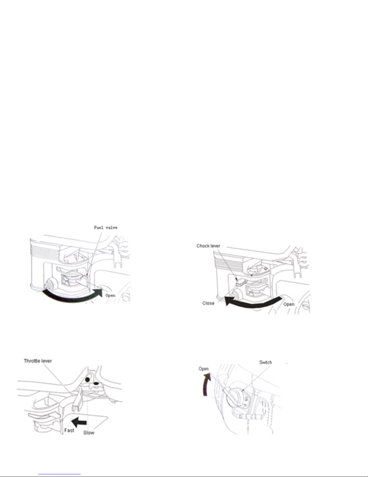
a. Move the fuel valve lever to the ON position.
c. Move the throttle lever away from the
SLOW position, about 1/3 of the way to
toward the FAST position.
b. Move the choke lever to the CLOSE position. If the engine is
warm or the air temperature is high, move the control lever away
from the OPEN position as soon as the engine starts.
d. Turn the engine switch to the ON position.
6
e. Pull the starter grip lightly until you feel resistance,
then pull briskly. Return the starter grip gently.
CAUTION! Do not allow the starter grip to snap back
against the engine. Return it gently to prevent damage
to the starter.
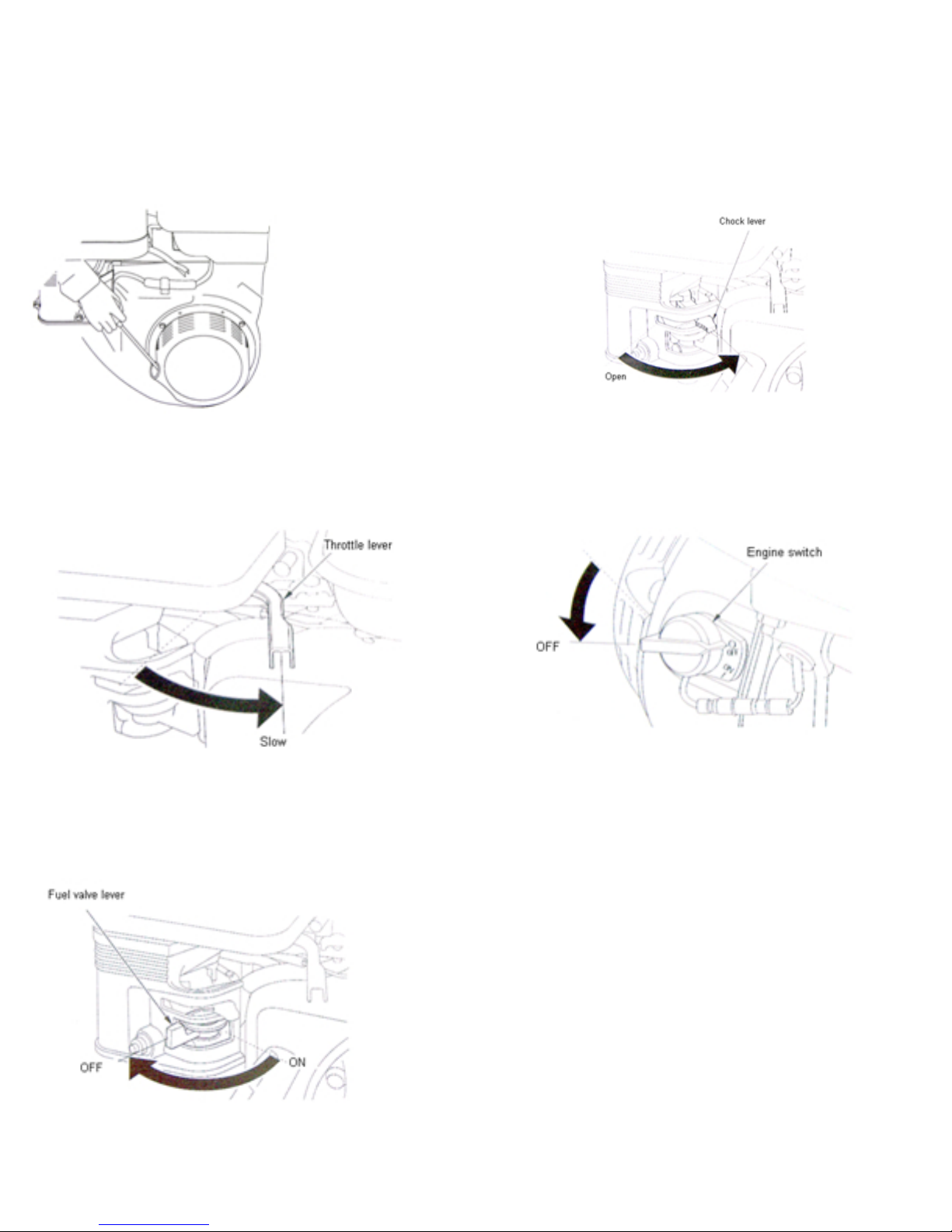
3. Stopping the engine
a. Move the throttle lever to the SLOW position.
f. If the chock lever or chock rod (applicable types) has been
moved to the CLOSED position to start the engine,
gradually move it to the OPEN position as the engine warms
up.
b. Turn the engine switch to the OFF position.
c. Turn the fuel valve lever to the OFF position.
4. Setting engine speed
Position the throttle lever the desired engine speed.
 Loading...