


An ISO 9001:2008 Company
®
G-17, Bharat Industrial Estate, T. J. Road, Sewree (W), Mumbai - 400 015. INDIA.
Sales Direct.: 022 -24156638, Tel. : 022-241224540, 24181649, Fax : 022 - 24149659
Email : kusam_meco@vsnl.net, Website : www.kusamelectrical.com
An ISO 9001:2008 Company
®
All Specifications are subject to change without prior notice
Navin.com/D.drive/sandeep gupta/New catlog Dec 2011/2772.cdr
NON-CONTACT EF-DETECTION
Model - 2772
20 FUNCTIONS 21 RANGES
2000 A AC TRUE RMS DIGITAL CLAMP METER WITH
? 2000A AC Clamp-on + Full Multimeter ranges
? AC True RMS Voltage & Current functions
? Autocheck feature (Automatic DCV, ACV &
Ohms selection)
? Fully Autoranging on all functions
? Back lighted display & Data Hold function
SPECIAL FEATURES :
? Non-Contact & Probe Contact EF-Detection
? Lo-Z Voltage to drain Ghost Voltages (Auto-VW position)
? High Voltage frequency with auto-ranging trigger levels
? Overload-Alert ON > 600V AC/DC (Beeps & OL indication)
? Fast Audible Continuity & Diode Test
GENERAL SPECIFICATIONS :
ï Sensing : True RMS sensing
í Jaws opening size : 45mm max.
í Display : 3-5/6 digits 6000 counts
í Update Rate : 5 per second nominal
í Polarity : Automatic
í Operating Temperature : 0°C ~ 40°C
í Relative Humidity : Max. R.H. 80% for
o
temperature upto 31 C decreasing linearly to
o
50% R.H. at 40 C
o o
í Storage Temperature : -20C to 60 C, < 80% R.H.
(With battery removed)
í Altitude : Operating below 2000m
í Temperature Coefficient : Nominal 0.15 x (specified accuracy) /
o oo oo
C @ (0 C ~ 18 C or 28 C ~ 40 C) or otherwise specified.
í Low Battery Indication : Below approx. 2.4 V
í Power Supply : Standard 1.5V AAA battery X 2
í Power Consumption : 2.8mA typical
í APO Consumption : 230 mA typical on Voltage & Current function
í APO Timing : Idle for 3 minutes
í Dimension : 224(L) x 78(W) x 40(H)mm
í Weight : approx. 220gm
SAFETY :
? Safety : Meets IEC 61010-2-032(1994),
EN61010-2-031(1995), UL3111-2-032 (1999)
? Measurement Category : CAT III 600VAC & VDC.
? Pollution degree : 2
? Overload Protection :
ACA Clamp-on jaws : AC 2000A rms continuous
+ & COM terminals (all functions) : 600VDC & VAC rms
? E.M.C. : Meets EN61326 (1997,1998/A1),
EN61000 -4-2 (1995) & EN61000-4-3 (1996)
In an RF Field of 3V/m :
Capacitance function is not specified.
Other function ranges :
Total accuracy = Specified accuracy+ 45 digits
Performance above 3V/m is not specified
? Battery Cover with probe holders
? Rugged fire retarded casing
ACCESSORIES :
Test leads (pair), Batteries installed, Users Manual, Carrying Case
ELECTRICAL SPECIFICATIONS : 2772
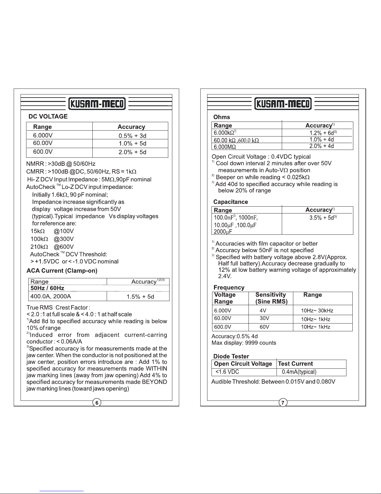
Accuracy : ± ( % reading + number of digits)
<1.6V DC
0.4mA typical
DIODE TESTER
Open Circuit Voltage
Test Current
Audible Threshold : between 0.015V and 0.080V
50Hz / 60Hz
50Hz ~ 500Hz
AC VOLTAGE
Range
6.000 V
60.00 V
Accuracy
±(1.5%rdg + 5dgts)
±(2.0%rdg + 5dgts)
Resolution
15kW
100kW
210kW
@ 100V
@ 300V
@ 600V
CMRR : > 60dB @ DC to 60 Hz; Rs =1kW
Hi-Z ACV Input Impedance : 5 MW, 90pF nominal
AutoCheck Lo-Z DCV Input Impedance :
Initially 1.6kW, 90pF nominal ;
Impedance increases significantly as display voltage
increases from 50V (typical). Typical impedances vs
display voltages for reference are:
AutoCheck ACV Threshold : > 2V AC (50 / 60Hz) nominal
Crest Factor : < 1.6:1 at full scale & < 3.3:1 at half scale
600.0 V
6.000 V
60.00 V
600.0 V
±(2.0%rdg + 5dgts)
±(2.5%rdg + 5dgts)
1 mV
10 mV
100 mV
1 mV
10 mV
100 mV
2)
100.0 nF
1000 nF
10.00 mF
100.0 Fm
2000 Fm
3)
±(3.5%rdg + 5dgts)
Range
Resolution
1)
Accuracy
CAPACITANCE
1) Accuracies with film capacitor or better.
2) Accuracy below 50 nF is not specified
3) Specified with battery voltage above 2.8V approx.
(half full battery).
Accuracy decreases gradually to 12% at low battery
warning voltage of approx 2.4V
100 pF
1 nF
10 nF
100 nF
1 mF
NON-CONTACT EF-DETECTION
Typical Voltage
Bar Graph Indication
15V to 85V
40V to 130V
60V to 210V
90V to 300V
above 120V
-
- -
- - -
- - - -
- - - - -
Indication : Bar graph segments & audible beep tones
proportional to the field strength
Detection Frequency : 50/60Hz
Detection Antenna : Top side of the stationary jaw
Probe-Contact EF-Dection : For more precise indication of
live wires, use the Red(+) probe for direct contact measurement
50Hz / 60Hz
Range
400.0 A
2000 A
±(1.5%rdg + 5dgts)
Resolution
ACA CLAMP-ON CURRENT
1) 2) 3)
Accuracy
Crest Factor : < 2 at full scale & < 4 at half scale
1)
Add 8d to specified accuracy while reading is below 10%
of range.
2)
Induced error from adjacent current-carrying conductor :
< 0.06A/A.
3)
Specified accuracy is for measurement made at the jaw
center. When the conductor is not positioned at the jaw
center, position errors introduced are:
Add 1% to specified accuracy for measurementts made
WITHIN jaws marking lines (away from jaws opening).
Add 4% to specified accuracy for measurements made
BEYOND jaws marking lines (toward jaws opening).
100 mA
1 A
2)
6.000 kW
60.00 kW
600.0 kW
6.000 MW
Range
3)
±(1.2%rdg + 6dgts)
±(2.0%rdg + 4dgts)
Resolution
RESISTANCE
1)
Accuracy
±(1.0%rdg + 4dgts)
Open Circuit Voltage : 0.4VDC typical
1)
Cool down interval 2 minutes after over 50V
measurements in Auto-VW position.
2)
Beeper ON while reading < 0.025 kW
3)
Add 40d to specified accuracy while reading is below
20% of range.
1 W
10 W
100 W
1 kW
6.000 V
60.00 V
600.0 V
FREQUENCY
4 V
10Hz ~ 30KHz
30 V
10Hz ~ 1KHz
60 V
10Hz ~ 1KHz
Voltage
Range
Sensitivity
(Sine RMS)
Range
Accuracy : ±(0.5%rdg + 4dgts)
Max display : 9999 counts
600W with CONTINUITY BEEPER
Accuracy
600.0 kW
1)
±(2.0%rdg + 8dgts)
Range
Continuity Beeper Response : <100mS
Open Circuit Voltage : 0.4VDC typical
Audible Threshold : between 10W and 300W
1)
Add 40d to specified accuracy while reading is
below 20% of range
DC VOLTAGE
Range
6.000 V
60.00 V
600.0 V
15 kW
100 kW
210 kW
@ 100 V
@ 300 V
@ 600 V
Accuracy
±(0.5%rdg + 3dgts)
±(1.0%rdg + 5dgts)
±(2.0%rdg + 5dgts)
Resolution
NMRR : > 30 dB @ 50 Hz / 60 Hz
CMRR : > 100 dB @ DC, 50 Hz / 60 Hz; Rs =1kW
Hi-Z DCV Input Impedance : 5 MW, 90pF nominal
AutoCheck DCV Threshold :
> + 1.5VDC or < -1.0VDC nominal
AutoCheck Lo-Z DCV Input Impedance :
Initially 1.6 kW, 90pF nominal ;
Impedance increases significantly as display voltage
increases from 50V (typical). Typical impedances vs
display voltages for reference are:
1 mV
10 mV
100 mV
Transient Protection
6.5kV (1.2/50
ms)
surge

®
USE TRUE RMS WHEN MEASURING
The waveforms on today’s AC power lines are anything but clean. Electronic equipment such as office computers, with their switching
power supplies, produce harmonics that distort power-line waveforms. These distortions make measuring AC voltage inaccurate
when you use an averaging DMM.
Average voltage measurements work fine when the signal you’re measuring is a pure sine wave, but errors mount as the waveform
distorts. By using true RMS measurements, however, you can measure the equivalent heating effect that a voltage produces,
including the heating effects of harmonics. Table 1 shows the difference between measurements taken on averaging DMMs & those
taken on true RMS DMMs. In each case, the measured signal’s peak-to-peak value is 2V. Therefore, the peak value is 1V.
For a 1-V peak sine wave, the average & RMS values are both 0.707V. But when the input signal is no longer a sine wave, differences
between the RMS values & the average readig values occur. Those errors are most prominent when you are measuring square waves
& pulse waveforms, which are rich in harmonics.
AC WAVEFORMS
Table 1. Average versus true RMS comparison of typical waveforms.
Waveform Actual
Pk-Pk
Sine Wave
Triangle Wave
Square Wave
Pulse (25% duty Cycle)
Pulse (12.5% duty Cycle)
Pulse (6.25% duty Cycle)
2.000 0.707 0.707 0%
2.000 0.577 0.555
2.000 1.000 1.111
2.000 0.433 0.416
2.000 0.331 0.243
2.000 0.242 0.130
True RMS
Reading
Average
Reading
Reading
Error
-3.8%
+11.1%
-3.8%
-26.5%
-46.2%
One limitation to making true RMS measurements is crest factor, and you should consider crest factor when making AC measurements.
Crest factor is the ratio of a waveform’s peak (”crest”) voltage to its RMS voltage. Table 2 shows the crest factors for ideal waveforms.
Table 2. Crest factors of typical waveforms.
Waveform
DC
Square Wave
Sine Wave
Triangle Wave
Pulse (25% duty Cycle)
Pulse (12.5% duty Cycle)
Pulse (6.25% duty Cycle)
A DMM’s specifications should tell you the maximum crest factor that the meter can handle while maintaining its measurement
accuracy. True RMS meters can handle higher crest factors when a waveform’s RMS voltage is in the middle of the meter’s range
setting. Typically, a DMM may tolerate a crest factor of 3 near the top of its scale but it might handle a crest factor of 5 that’s in the
middle of the range. Therefore, if you’re measuring waveforms with high crest factors (greater than 3), you should adjust the DMM
so the measured voltage is closest to the center of the measurement range.
Another limitation of true RMS is speed. If you’re measuring relatively clean sine waves, then you can save time & money by using as
averaging DMM. True RMS meters cost more than averaging meters and can take longer to produce measurements, especially when
measuring millivolt-level AC signals. At those low levels, true RMS meters can take several seconds to stabilize a reading. Averaging
meters won’t leave you waiting.
Crest Factor
1.000
1.000
1.414
1.732
1.732
2.646
3.873
D:/Chhaya/Coreldraw files/True RMS when measuring AC waveforms.cdr


MODEL NO. ___________
This Test Certificate warrantees that
the product has been inspected and
tested in accordance with the published
specifications.
The instrument has been calibrated by
using equipment which has already
been calibrated to standards traceable
to national standards.
2772
SERIAL NO. ___________
DATE: ___________
ISO 9001
REGISTERED
QC
PASS
KUSAM-MECO

WARRANTY
Each “KUSAM-MECO” product is warranted to be
free from defects in material and workmanship
under normal use & service. The warranty period is
one year (12 months) and begins from the date of
despatch of goods. In case any defect occurs in
functioning of the instrument, under proper use,
within the warranty period, the same will be rectified
by us free of charges, provided the to and fro freight
charges are borne by you.
This warranty extends only to the original buyer or
end-user customer of a “KUSAM-MECO” authorized
dealer.
This warranty does not apply for damaged Ic’s,
fuses, burnt PCB's, disposable batteries, carrying
case, test leads, or to any product which in “KUSAMMECO’s” opinion, has been misused, altered,
neglected, contaminated or damaged by accident or
abnormal conditions of operation or handling.
“KUSAM-MECO” authorized dealer shall extend this
warranty on new and unused products to end-user
customers only but have no authority to extend a
greater or different warranty on behalf of “KUSAMMECO”.
“KUSAM-MECO’s” warranty obligation is limited, at
option, free of charge repair, or replacement of a
defective product which is returned to a “KUSAMMECO” authorized service center within the
warranty period.
THIS WARRANTY IS BUYER’S SOLE AND
EXCLUSIVE REMEDY AND IS IN LIEU OF ALL
OTHER WARRANTIES, EXPRESS OR IMPLIED,
INCLUDING BUT NOT LIMITED TO ANY IMPLIED
WARRANTY OF MERCHANTA B ILITY OR
FITNESS FOR A PARTICULAR PURPOSE.
“KUSAM-MECO” SHALL NOT BE LIABLE FOR
ANY SPECIAL, INDIRECT, INCIDENTAL OR
CONSEQUENTIAL DAMAGES OR LOSSES,
INCLUDING LOSS OF DATA, ARISING FROM
ANY CAUSE WHATSOEVER.
All transaction are subject to Mumbai Jurisdiction.
 Loading...