

Page 1

Mark PRO 2i
Service Manual
2007 All rights reserved. Kurzweil is a product line of Young Chang Co.; Kurzweil is a trademark of Young Chang Co. All other products
and brand names are trademarks or registered trademarks of their respective companies.
Product features and specifications are subject to change without notice.
Page 2

IMPORTANT SAFETY & INSTALLATION INSTRUCTIONS
INSTRUCTIONS PERTAINING TO THE RISK OF FIRE, ELECTRIC SHOCK, OR INJURY TO PERSONS
WARNING: When using electric products, basic precautions
should
always be followed, including the following:
1. Read all of the Safety and Installation Instructions and
Explanation of Graphic Symbols before using the product.
2. Do not use this product near water—for example, near a
bathtub, washbowl, kitchen sink, in a wet basement, or near a
swimming pool, or the like.
3. This product should be used only with a stand or
cart that is recommended by the manufacturer.
4. This product, either alone or in combination with an amplifier
and speakers or headphones, may be capable of
producing sound levels that could cause permanent hearing loss.
Do not operate for
a long period of time at a high volume level or at a level that is
uncomfortable. If you experience any hearing loss or ringing in the
ears, you should consult an audiologist.
5. The product should be located so that its location or position
does not interfere with its proper ventilation.
6. The product should be located away from heat sources such
as radiators, heat registers, or other products that produce heat.
7. The product should be connected to a power supply only of the
type described in the operating instructions or as marked on the
product.
8. This product may be equipped with a polarized line plug (one
blade wider than the other). This is a safety feature. If you are
unable to insert the plug into the outlet, contact an electrician to
replace your obsolete outlet. Do not defeat the safety purpose of
the plug.
9. The power supply cord of the product should be unplugged from
the
outlet when left unused for a long period of time. When unplugging
the power supply cord, do not pull on the cord, but grasp it by the
plug.
10. Care should be taken so that objects do not fall and liquids are not
spilled into the enclosure through openings.
11. The product should be serviced by qualified service
personnel when:
A. The power supply cord or the plug has been damaged;
B. Objects have fallen onto, or liquid has been spilled into
the product;
C. The product has been exposed to rain;
D. The product does not appear to be operating
normally or exhibits a marked change in performance;
E. The product has been dropped, or the enclosure damaged.
12. Do not attempt to service the product beyond that described in
the user maintenance instructions. All other servicing
should be referred to qualified service personnel.
13. WARNING: Do not place objects on the product’s power
supply cord, or place the product in a position where anyone
could trip over, walk on, or roll anything over cords of any type.
Do not allow the product to rest on or be installed over
cords of any type. Improper installations of this type
create the possibility of a fire hazard and/or personal injury.
RADIO AND TELEVISION INTERFERENCE
WARNING: Changes or modifications to this instrument not expressly
approved by Young Chang could void your authority to
operate the instrument.
IMPORTANT: When connecting this product to accessories and/or other
equipment use only high quality shielded cables.
NOTE: This instrument has been tested and found to comply with the
limits for a Class A digital device, pursuant to Part 15 of the FCC Rules.
These limits are designed to provide reasonable protection
against harmful interference when the instrument is used in
a commercial environment. This instrument generates, uses,
and can radiate radio frequency energy and, if not installed and
used in accordance with the instruction manual, may cause
harmful interference to radio communications. Operation of
this instrument in a residential area is likely to cause
harmful interference, in which case the user will be required
to correct the interference at his or her own expense.
Changes and modifications not expressly approved by the manufacturer
or registrant of this instrument can void the user’s authority to operate
this instrument under Federal Communications Commission rules.
In order to maintain compliance with FCC regulations, shielded cables
must be used with this instrument. Operation with
unapproved equipment or unshielded cables is likely to result in harmful
interference to radio and television reception.
NOTICE
This apparatus does not exceed the Class A limits for
radio noise emissions from digital apparatus set out in the
Radio Interference Regulations of the Canadian Department of
Communications.
AVIS
Le present appareil numerique n’emet pas de bruits
radioelectriques depassant les limites applicables aux
appareils numeriques de la class A prescrites dans le
Reglement sur le brouillage radioelectrique edicte par le ministere des
Communications du Canada.
SAVE THESE INSTRUCTIONS
Page 3

Young Chang Distributors
Contact the nearest Young Chang office listed below to locate your local Young
Chang/Kurzweil representative
YOUNG CHANG Headquarters
9FL, 102-Dong, I’PARK, Jeoungja-Dong,
Buandan-Gu, Seongnam-Si, Gyeonggi-Do, Korea
463-859
Tel : 1-82-31-786-7900
Fax : 1-82-31-785-2703
Web : www.yapiano.co.kr
YCNA(Young Chang North America)
19060 S Dominguez Hills, Dr Rancho Dominguez,
CA 90220, U.S.A
Tel : 1-310-637-2000
Fax : 1-310-637-2025
Web : www.youngchang.com
YCRDI(Young Chang R&D Institute)
1432 Main Street Waltham, MA02451, U.S.A
Tel : 1-781-890-2929
Fax : 1-781-890-2014
Web : www.kurzweilmusicsystems.com
.
1
Page 4

Contents
MARK PRO 2I
IMPORTANT SAFETY & INSTALLATION INSTRUCTIONS
CONTENTS
CHAPTER 1 INTRODUCTION
Introduction to Mark Pro 2i .........................................................................................................................................................5
Mark Pro 2i Rear Panel
Rear Panel Features
Mark Pro 2i Front Panel
Front Panel Features
Power On. Off.
CHAPTER 2 MARK PRO 2I ASSEMBLY
Introduction .................................................................................................................................................................................10
Cables, Connectors
Installation....................................................................................................................................................................................11
Checking the Parts
Check that you have all the parts below before you start assembling..................................................................11
Assembling the Stand
Disassembling the Main set
Check the 5 steps below before you start disassembling. .......................................................................................15
Removing the Scanner Board
Removing the Amp Board
Removing the Front Panel Board
................................................................................................................................... 1
............................................2
......................................................................................................................................... 2
...................................................................................................... 4
.........................................................................................................................................................5
..............................................................................................................................................................5
........................................................................................................................................................6
.............................................................................................................................................................7
.........................................................................................................................................................................9
................................................................................10
.............................................................................................................................................................10
..............................................................................................................................................................11
.........................................................................................................................................................12
..............................................................................................................................................15
...........................................................................................................................................18
..................................................................................................................................................20
.....................................................................................................................................21
CHAPTER 3 DIAGNOSTICS
Diagnostic Tests.............................................................................................................................................................................25
Entering Diagnostics....................................................................................................................................................................26
Diagnostic Test Modes ..................................................................................................................................................................27
Run One Test
Run Burn Test
Test Results
Description of Tests
.........................................................................................................................................................................................28
ROM
.........................................................................................................................................................................................28
RAM
Sine Wave
NVRAM
.........................................................................................................................................................................27
.......................................................................................................................................................................27
...........................................................................................................................................................................28
............................................................................................................................................................28
..............................................................................................................................................................................29
....................................................................................................................................................................................30
CHAPTER 4 TROUBLESHOOTING
Introduction..................................................................................................................................................................................31
Cables, Connectors
Boot Block..................................................................................................................................................................................31
Entering the Boot Block
Hard Reset
.............................................................................................................................................................................33
.............................................................................................................................................................31
.....................................................................................................................................................31
....................................................................................................... 25
......................................................................................... 31
2
Page 5

Software Updates.........................................................................................................................................................................33
File Formats
Replacing the Battery..................................................................................................................................................................35
Mark Pro 2i Scanner test ............................................................................................................................................................37
Power Problems...........................................................................................................................................................................38
.........................................................................................................................................................................................38
Dead
Audio Problems............................................................................................................................................................................39
No Audio
Front Panel Problems ..................................................................................................................................................................39
Buttons, Knobs or Controllers not working
Keyboard Problems......................................................................................................................................................................40
Dead Keyboard
...........................................................................................................................................................................33
.................................................................................................................................................................................39
..................................................................................................................39
.....................................................................................................................................................................40
CHAPTER 5 PARTS LISTS
Introduction..................................................................................................................................................................................42
Mark Pro 2i Printed Circuit Boards and Assemblies
Engine Board
Scanner Board
Audio Board
Front Board
Head Phone Board
.........................................................................................................................................................................43
......................................................................................................................................................................47
...........................................................................................................................................................................48
............................................................................................................................................................................50
...............................................................................................................................................................51
CHAPTER 6 SCHEMATICS
Engine Board Micro Processor(68331) Interface
Engine Board DRAM, LEVEL, SHIFTER
Engine Board MARA
Engine Board Sound ROM, UART, USB, BRIDGE
Engine Board POWER, CLOCK, PLL
Scanner Board 38869 Interface
Scanner Board Front Interface
Front Board Left
Front Board Right
Amp Board Engine IO, MIDI IN & OUT
Amp Board Speaker, Line IN & OUT, Headphone
............................................................................................................................................................54
...................................................................................................................................................................59
................................................................................................................................................................60
......................................................................................................... 42
..................................................................................................42
........................................................................................................ 52
.........................................................................................................52
.........................................................................................................................53
.......................................................................................................55
..............................................................................................................................55
........................................................................................................................................56
.........................................................................................................................................58
............................................................................................................................61
........................................................................................................62
3
Page 6

Chapter 1
Introduction
This chapter provides the service technician with a layout of the front and rear panel features, as well as a brief
explanation of their functions. For in-depth descriptions of the many features the Mark PRO 2i instruments include,
consult the Musician’s Guide.
This chapter also includes a description the symbols used throughout this manual.
Notes, Cautions, Warnings
Please pay special attention to all Notes, Cautions, and Warnings used throughout this manual. A brief description
of these symbols follows:
Note: If possible, all user programs and setups should be saved prior to opening the unit,
entering the Boot Block to run diagnostics or to perform a hard reset. For instructions to
save all user programs and setups.
Note: Provides additional information emphasizes specific instructions.
Caution: Instructs you to proceed cautiously so that damage does not occur to the unit or
individual components
Warning: Alerts you so that damage does not occur to yourself, others, or external devices.
.
4
Page 7
Mark Pro TWOi
Introduction to Mark Pro 2i
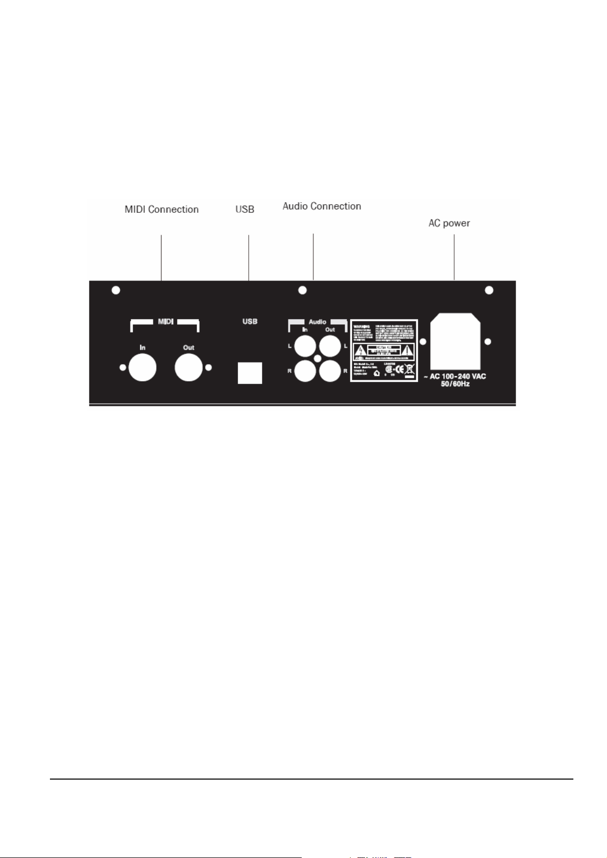
Mark Pro 2i Rear Panel
Figure 1-1 Mark PRO 2i rear panel
Rear Panel Features
Power Connector— AV 100~240 VAC 50/60Hz
Audio Connection – Balanced 1/4” left and right audio output jacks to connect to an amplifier,
mixer or sound system.
MIDI Connection – In, Thru/Out, and Out ports to connect the Mark Pro 2i to other MIDI
devices to receive, pass, and send MIDI data.
USB – Transmit/receive MIDI message over USB with host system(typically, PC).
5
Page 8
Mark Pro TWOi
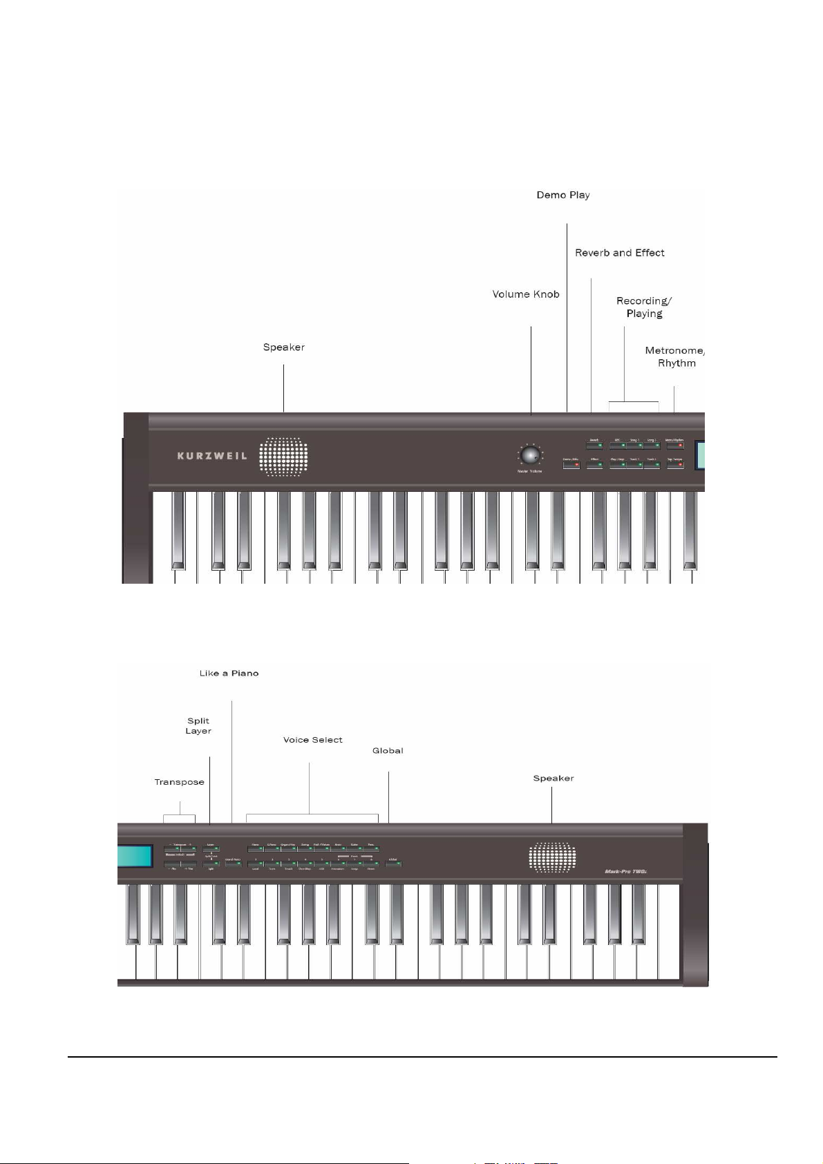
Mark Pro 2i Front Panel
Figure 1-2 Mark PRO 2i Front Left panel
Figure 1-3 Mark PRO 2i Front Right panel
6
Page 9
Mark Pro TWOi
Front Panel Features
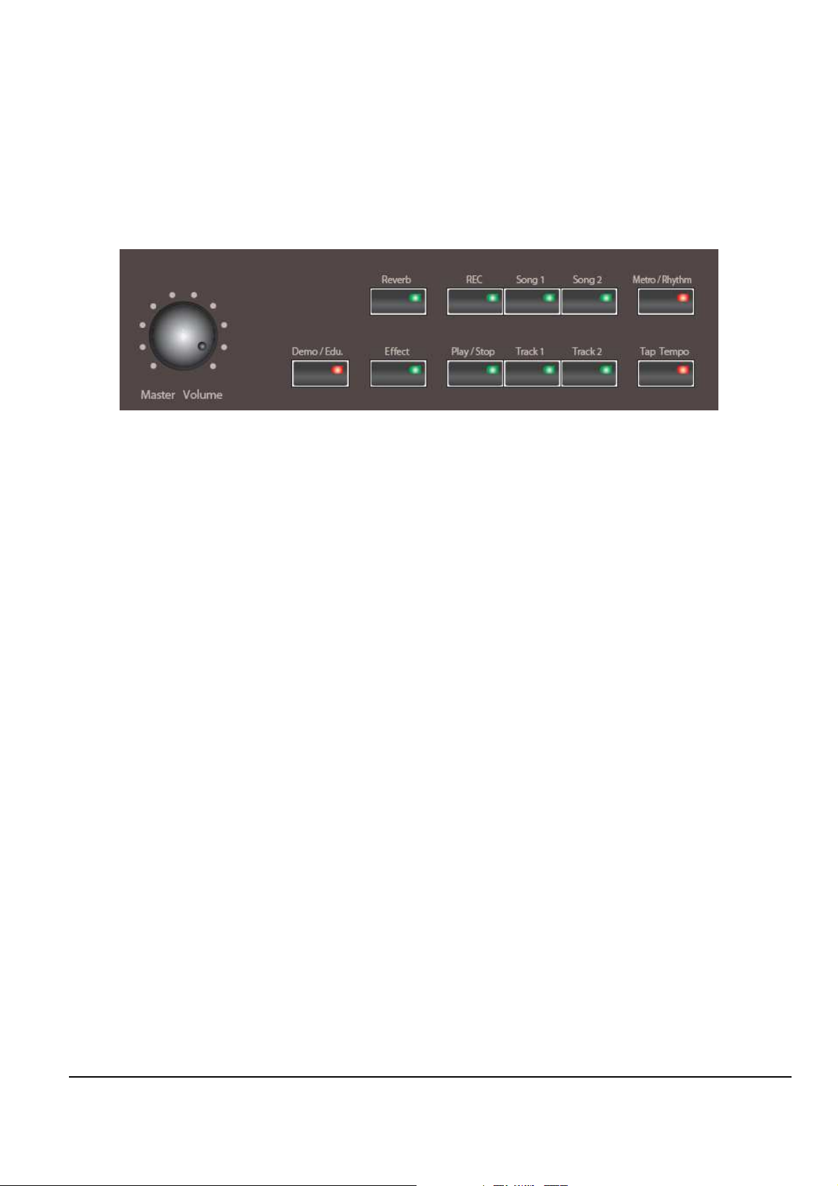
Figure 1-4 Mark PRO 2i Front left section
Volume Knob
( turn to the left is Soft, right is Loud )
Demo/Edu.
Effect & Reverb
Recording & Playing
Metro & Rhythm
—
Use the volume knob located on the far left of the front panel to adjust the
volume. Set the volume to the minimum when turning on the instrument and
adjust it to the desired level later. Moving the knob clockwise increases
volume, while moving it counter clockwise decreases volume.
—
The Mark-Pro 2i has 3 ensemble demos, 50 piano demos and
8 instrumental demos that will aquaint you with the sound of the Mark-Pro 2i.
—
Use the buttons to select from two blocks of effects to apply effects and
reverb to programs and setups.
—
The Mark-Pro 2i allows you to record and playback your performance.
Two song spaces are available each with two tracks.
—
Use the buttons, you can change the tempo of the metronome.
7
Page 10
Mark Pro TWOi
Figure 1-5 Mark PRO 2i Front center section
3 X 7 Segment
—
Three character & Seven segment display.
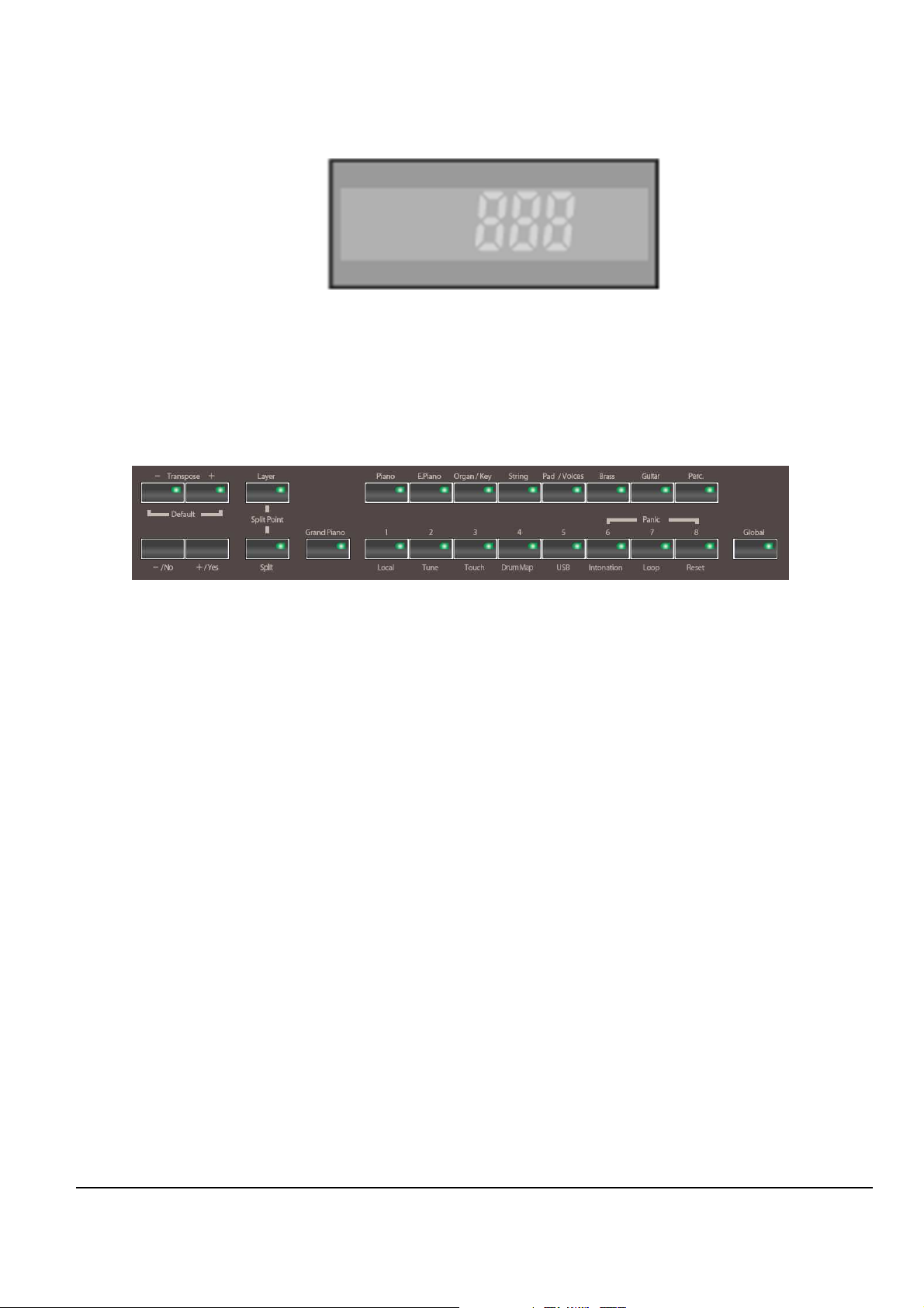
Figure 1-6 Mark PRO 2i Front right section
Transpose — Use this button to change tonality, using Transpose + / Transpose -
button can be up/down up to 2 octaves.
Split & Layer
—
Use the buttons you can add a voice other than strings or sounds (Layer)
and divide the keyboard of the Mark-Pro2i into two, left and right, and assign a
different voice for each(Split).
Grand piano — Use the button
all of the non piano functions.
Voice select
Global
—
Use the buttons selects the piano voice by default when turned on, which
can also be selected by the Grand Piano button on the left as shown in the
figure 1-6. And the Grand Piano voice, the Mark Pro-TWOi has 64 voices which
can be classified to as 8 categories: 8 piano voices, 8 elec pianos, 8 organs/
keyboards, 8 strings, 8 pads, 8 brasses, 8 guitars/voices, 8 percussion sets.
—
Use the button , in connection with the 8 buttons on its left (Local, Tune, Touch,
etc) lets you to control various functions affecting the keyboard globally.
can be just as simple to use as an acoustic piano by disabling
8
Page 11
Mark Pro TWOi
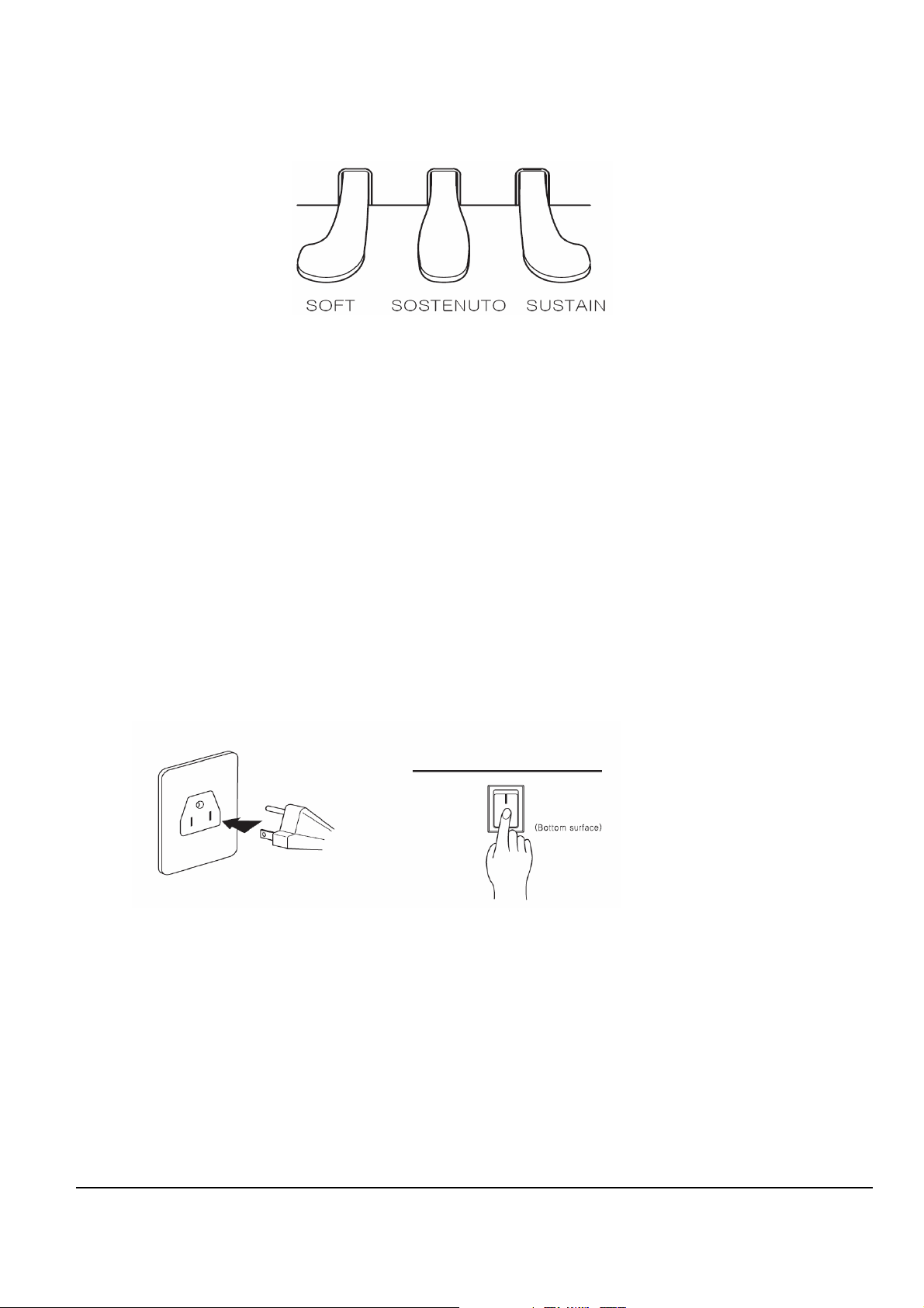
Figure 1-6 Mark PRO 2i Pedal
SUSTAIN
SOSTENUTO
SOFT
—
The Sustain pedal lets the notes ring on after the keys are released. Releasing
the pedal will silence the sustained notes.
—
Press the sostenuto pedal while holding a note on the keyboard, and the
note will sustain as long as you hold the pedal. But all the subsequently play
notes will not be sustained.
—
The soft pedal makes the volume softer when pressed. But it will not affect the
volume of notes that are already played.
Power On. Off.
Figure 1-7 Mark PRO 2i Power On & Off
The Mark Pro 2i is a free volt product which can be used both on 110V and 220V. You can
power this digital piano by plugging it into a standard household power outlet. Make sure the
power switch on the bottom surface of the keyboard is turned off before you connect the power
cord to the electrical outlet.
After connecting to the outlet, you may turn on the power switch located at the bottom left of the
keyboard. Check the main volume knob is fully down to the left. When the power switch is
turned on, the front panel lights up. In 3 seconds the Mark-Pro 2i is ready to play.
9
Page 12

Mark Pro TWOi
Chapter 2
Mark Pro 2i Assembly
Introduction
This chapter contains all the procedures for the disassembly and reassembly of Mark Pro 2i as
well as instruments with factory-installed. There are three main sections: Opening the Mark Pro
2i, Top Enclosure, Mark Pro 2 Keyboard Assembly.
Warning: If possible, save all user programs and setups before disassembly. For instructions.
Notes, Cautions, Warnings
Please pay special attention to all Notes, Cautions, and Warnings as they not only point out
specific instructions
.
Cables, Connectors
Flat Ribbon Cables
All flat ribbon cables with connectors are keyed, and therefore cannot be reversed. Most flat
ribbon cables have locking cable clips. Be sure to reapply the clips when connecting cables.
When disconnecting and connecting these cables, you must look for the marking on the edge of
cable denoting Pin 1 and be sure that you match it correctly with Pin 1 on the board.
the
Cable Routing
In some cases, tape secures cable connections or fastens cables to the Top enclosure. Always
peel back the tape from one side when disconnecting cables so that the tape remains properly
positioned.
Required Tools and Materials
screwdriver
-
10
Page 13
Mark Pro TWOi
Installation
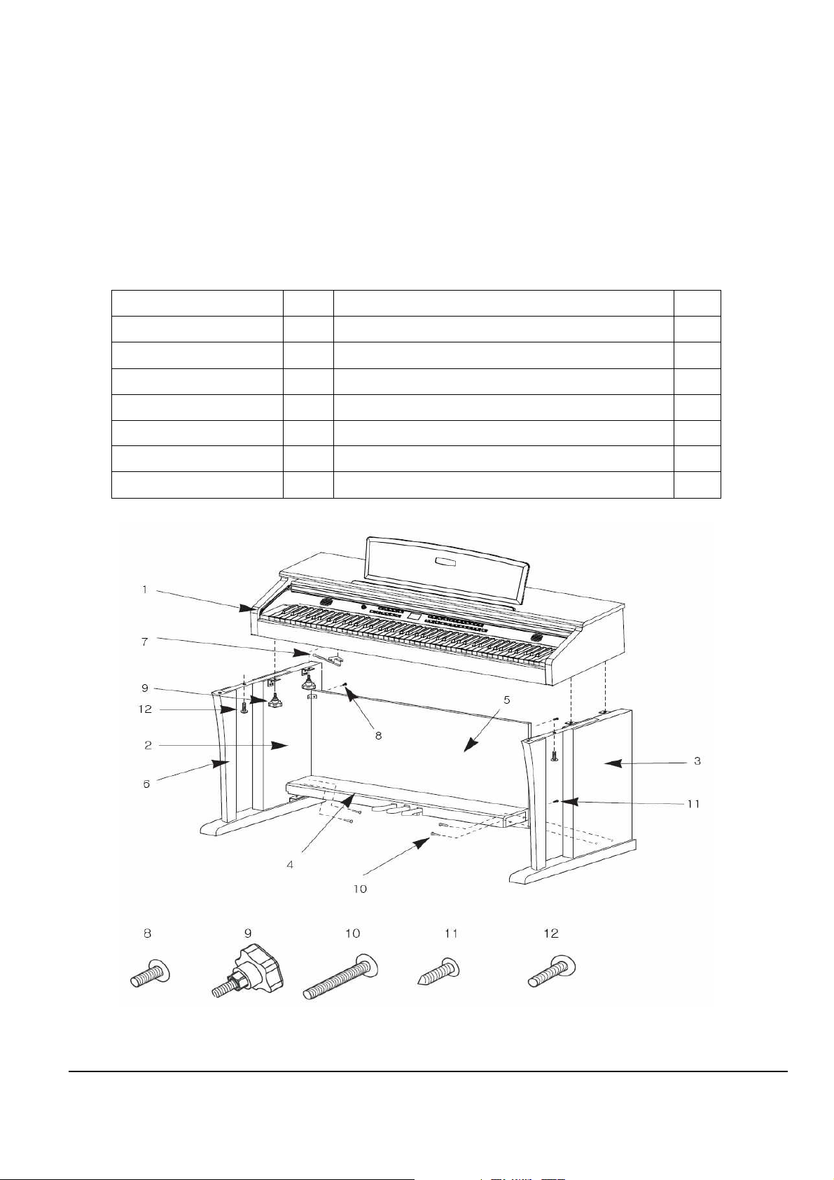
Checking the Parts
Check that you have all the parts below before you start assembling.
Item No. Item No.
1. Main set 1EA 8. Screws for Side Panel and Keyboard (Rear) 2EA
2. Side Panel (Left) 1EA 9. Screws for Side Panel and Keyboard (Front) 2EA
3. Side Panel (Right) 1EA 10. Screws for Side Panel and Pedal Box 4EA
4. Pedal Box 1EA 11. Screws for Rear Panel 2EA
5. Rear Panel 1EA 12. Screws for keyboard and the stand 4EA
6. Support Legs 2EA
7. Headphone Hanger 1EA
Table 2-1 Mark PRO 2i All the parts list
Figure 2-1 Mark PRO 2i Parts
11
Page 14
Mark Pro TWOi
Assembling the Stand
* Be careful when placing the Main set in the stand. Do not push down or pull forward
the Main set without tightening all the screws on the stand.
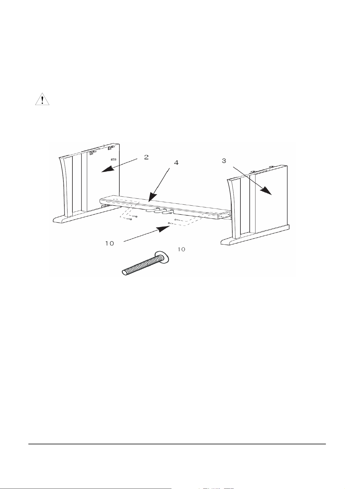
Side Panel and Pedal Assembly
Figure 2-2 Mark PRO 2i Side panel and Pedal Assembly
1. Place pedal box 4 on the left side panel 2 and fasten the screw 10 on the hole.
2. Put on the right side panel 3 in the same way.
3. Take out the pedal cable from inside of the pedal box 4.
12
Page 15
Mark Pro TWOi
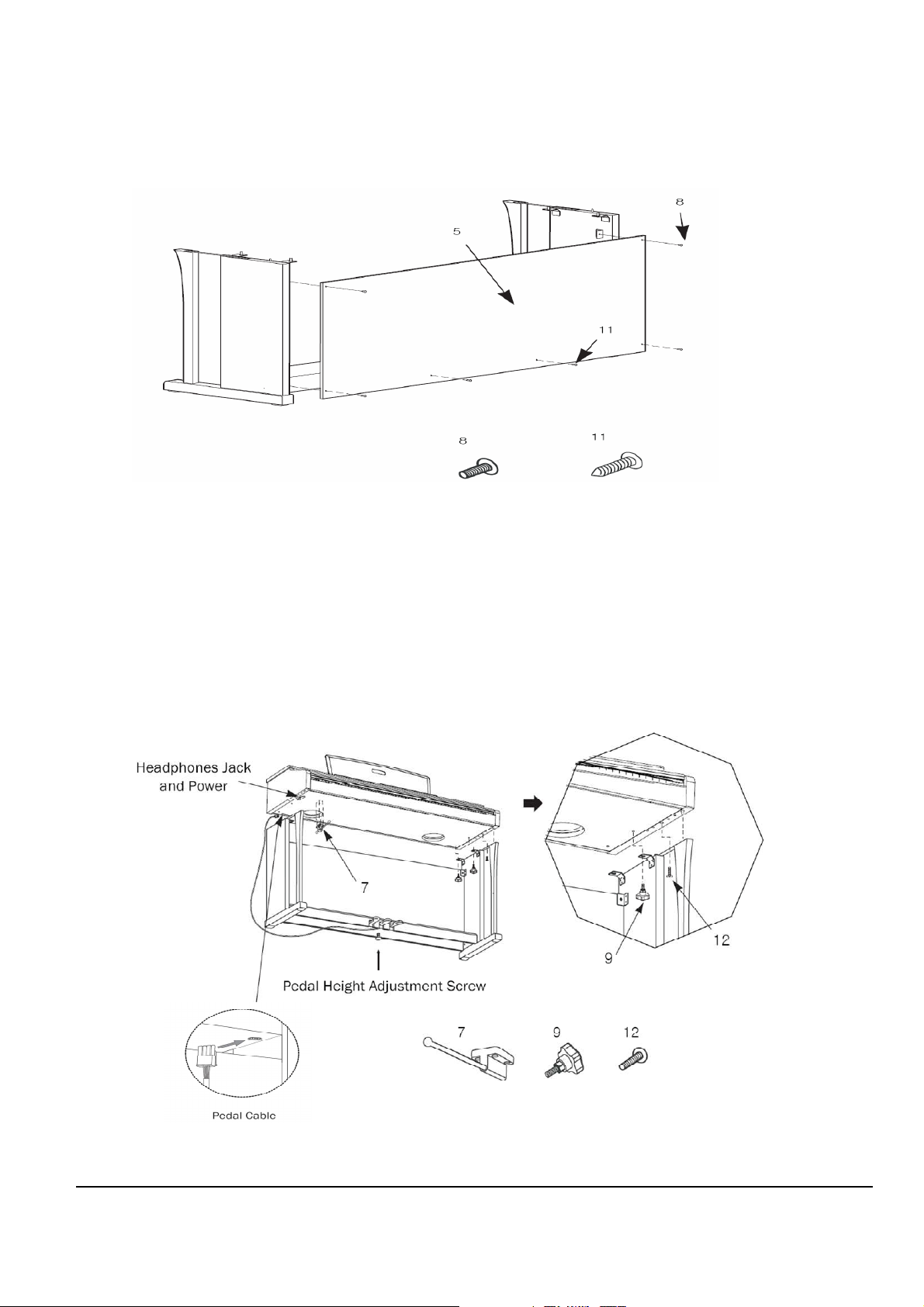
Rear Panel Assembly
Figure 2-3 Mark PRO 2i Rear panel Assembly
1. Fit the rear panel 5 into side panel brackets and fasten the screws 8.
2. After fastening all four screws of 8, fasten the screws 11 to lock to the pedal
box.
Installing the Main set onto the Stand
Figure 2-4 Mark PRO 2i Installing the Main set onto the Stand
13
Page 16

Mark Pro TWOi
1. Place the Main set on the stand so that the wood pegs on the top of the side
panel fit into the holes on the bottom surface of the keyboard.
2. Attach the side panels to the Main set with the metal brackets. Use the bolt 12
for the front hole, and 9 for the rear.
3. Insert the pedal cable connector to the jack on the bottom surface of the Main
set as shown in the left figure.
4. Locate the unit to the desired place and rotate the height adjustment screw until
it supports the pedal box, preventing the pedal box from bending when you
press the pedals.
Be sure to install the adjustment screw and perform the adjustment procedure
before depressing the pedals. Failure to do so may result in damage to the pedal
box.
5. Attach the headphone hanger wherever you wish.
Figure 2-5 Mark PRO 2i Headphone hanger
14
Page 17
Mark Pro TWOi
Disassembling the Main set
Check the 5 steps below before you start disassembling.
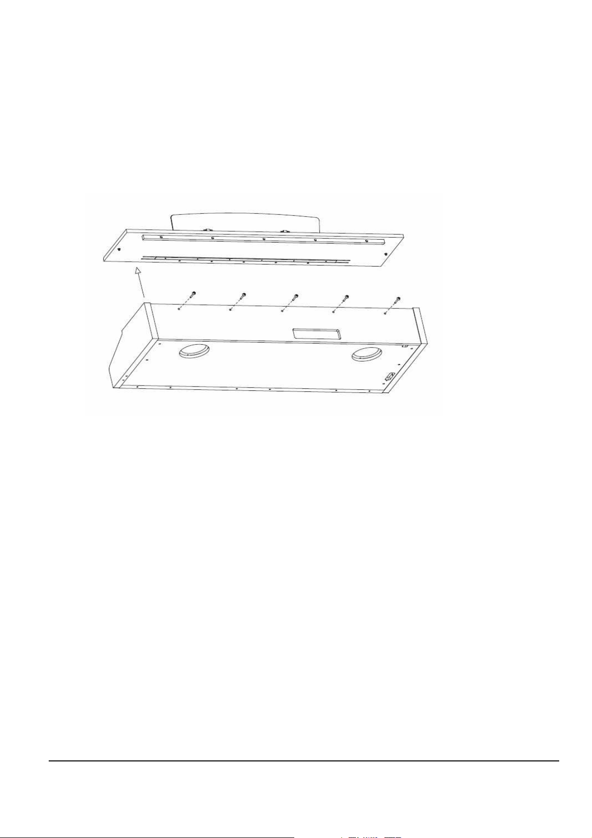
1. Top Cover Disassembly
Figure 2-6 Mark PRO 2i Disassemble top cover
15
Page 18
Mark Pro TWOi
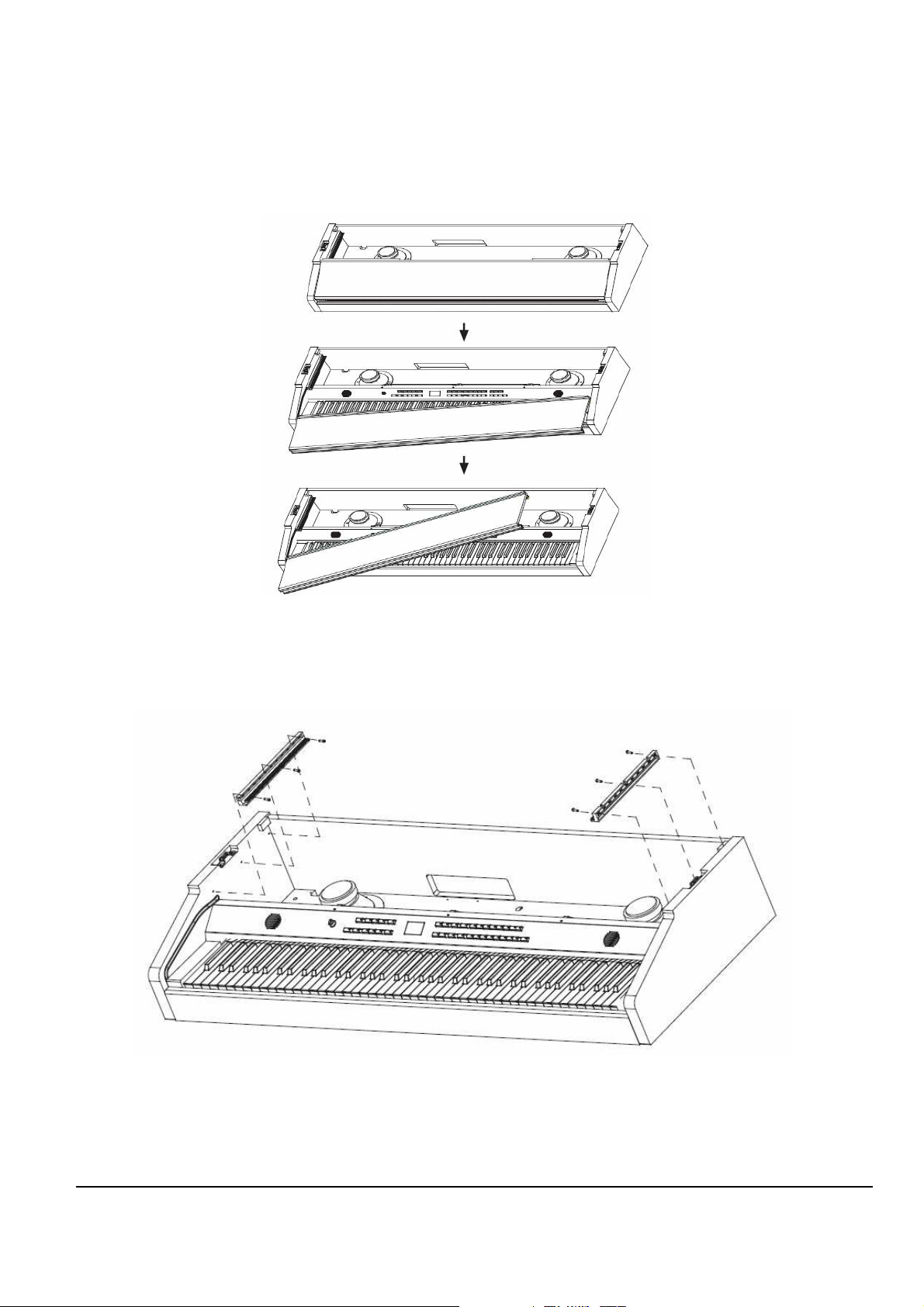
2. Dust Cover Disassembly
Figure 2-7 Mark PRO 2i Disassemble Dust cover
3. Grill Disassembly
Figure 2-8 Mark PRO 2i Disassemble Grill
16
Page 19
Mark Pro TWOi
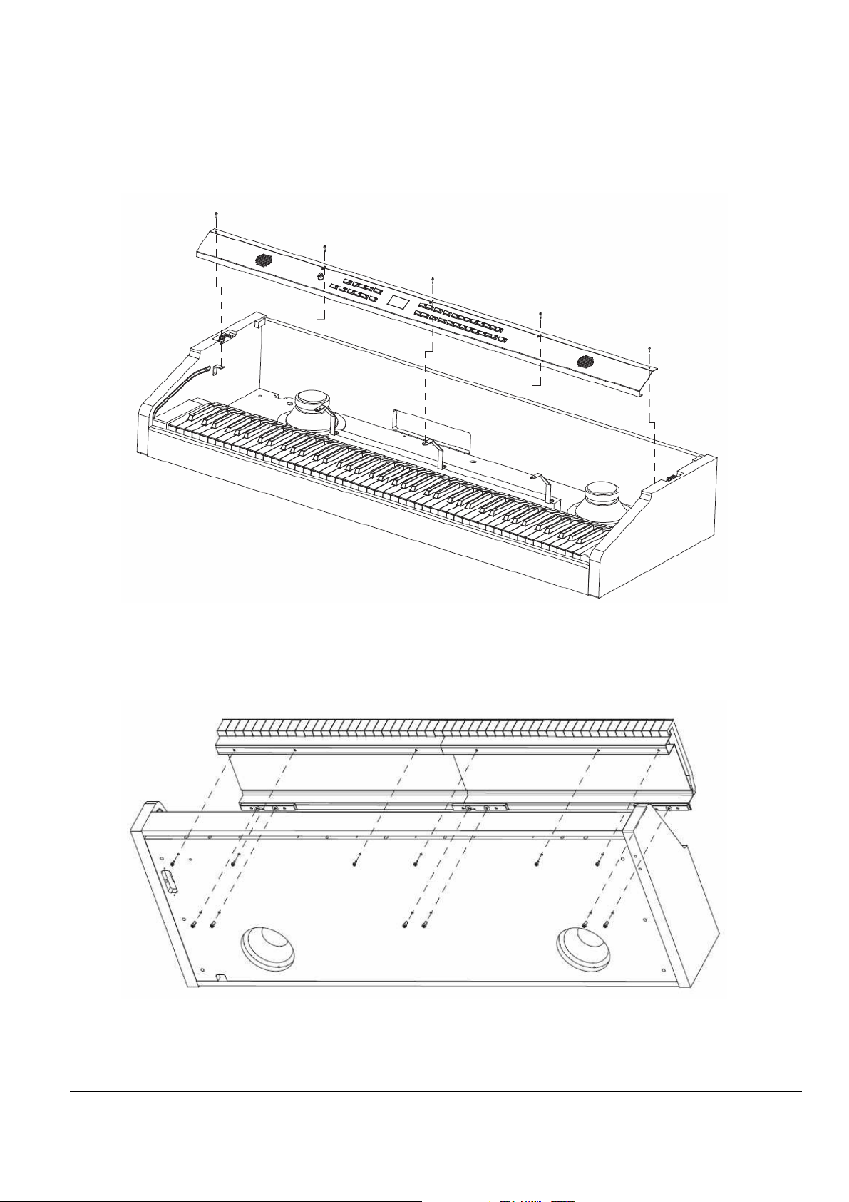
4. Front panel Disassembly
Figure 2-9 Mark PRO 2i Disassemble Front panel
5. Keyboard Disassembly
Figure 2-10 Mark PRO 2i Disassemble Keyboard
17
Page 20
Mark Pro TWOi
J
4 F
ront Panel flat ribbon F
ront Panel Board
J
2 Treb
le flat ribbon Keyboard Assem
b
ly
J
3 Bass
flat ribbon Keyboard Assem
b
ly
J12 Engine I/O
S
tandard wire
Amp Board
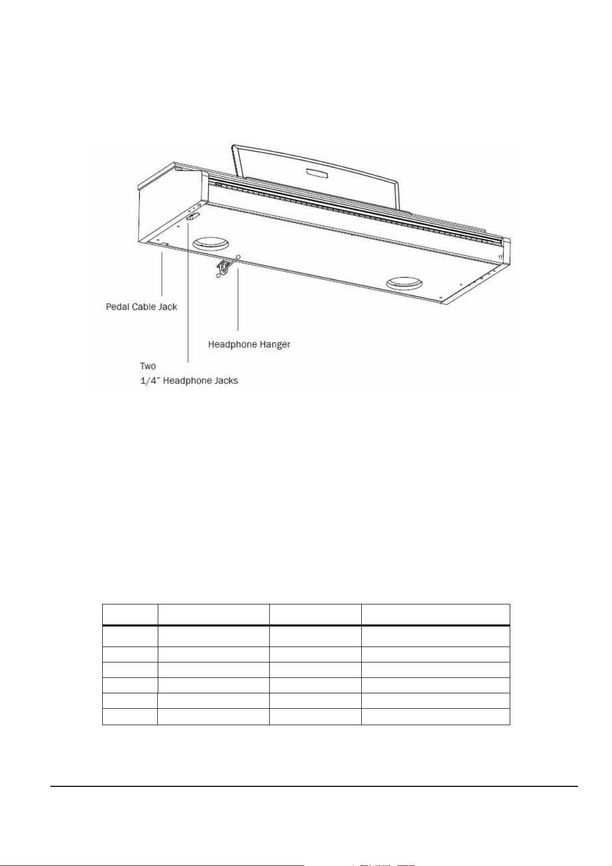
Bottom Surface
Figure 2-6 Mark PRO 2i Bottom surface
The Mark Pro2i has two 1/4” headphone jackes on the surface of the keyboard so that two can
listen and play at the same time. The volume for both jacks is controlled identically by the main
volume knob located at the far left side on the front panel.
Removing the Scanner Board
1. Follow the procedure described to remove the top panel Assy.
. Following Steps 3–5, disconnect the cables listed in Table 2-2
2
Ref. Name Cable Type Destination
J6
MIDI/CPU
standard wire
Engine Board
J9 Piano Pedals Standard wire Pedals
Table 2-2 Connector Board cables
18
Page 21

Mark Pro TWOi
3. Disconnect the hook-up wire cable on the Scanner Board.
4. Remove the cable locking clips and disconnect the flat ribbon cables from J2, J3, and J4. Be
sure to set the cable locking clips safely aside so that you can install them when you
reconnect the cables.
Note: The cables used throughout the
locations and destinations seem obvious. However, to avoid reversing the Bass and Treble
cables when reconnecting, mark one or both cables designating B for Bass and T for
5. Remove the all screws .
Note: Do not remove any other hardware from this portion of the rear panel.
6 . Remove the Scanner Board.
Mark PRO 2i
are bundled and routed so that their
Treble.
Replacing the Scanner Board
1. Hold the Scanner Board and position it so that the power switch, and the rear panel jacks
are correctly positioned through the rear panel portion of the top enclosure.
2. Install the all screws.
3. Connect the ribbon cables in the following order.
Caution: Be sure to look for the marking on the edge of the cable denoting Pin 1 and that you
match it correctly with Pin 1 on the board. Make certain that the wires are straight
prior to inserting them into the connector and that each wire is correctly inserted
into its respective position.
4. Connect the flat ribbon cables from the Keyboard Assembly to J2 and J3. Be sure to install
a cable locking clip on each connector.
19
Page 22

Mark Pro TWOi
J
3 Main Volume
standard wire
F
ront Panel Board
J
4
Headphone
standard wire
Headpho
ne
J
5 R-woofer
standard wire
Right Speaker
J
6 R-woofer
standard wire
Right Speaker
5. Connect the flat ribbon cable from the Front Panel Board to J4 on the Connector Board. Be
sure to install a cable locking clip on the connector.
6. Connect all the stranded wire cable from the Engine Board to the Scanner Board and from
Front board to Scanner board..
Removing the Amp Board
1. Follow the procedure described to remove the top panel Assy.
. Following Steps 3–5, disconnect the cables listed in Table 2-3
2
Ref. Name Cable Type Destination
J1
J7
J8
J11 Mark Pro 2i power standard wire Engine Board
J12 Engine I/O standard wire Scanner Board
J13 USB standard wire Scanner Board
J15 Audio standard wire Engine Board
Power supply
L-woofer
L-woofer
standard wire
standard wire
standard wire
POWER SUPPLY
Light Speaker
Light Speaker
Table 2-3 Amp Board cables
3. Disconnect the hook-up wire cable on the Amp Board.
4. Remove the cable locking clips. Be sure to set the cable locking clips safely aside so that
you can install them when you reconnect the cables.
5. Remove the all screws .
Note: Do not remove any other hardware from this portion of the rear panel.
6 . Remove the Amp Board.
20
Page 23

Mark Pro TWOi
Replacing the Amp Board
1. Hold the Amp Board and position it so that the power switch, and the rear panel jacks are
correctly positioned through the rear panel portion of the top enclosure.
2. Install the all screws.
3. Connect the ribbon cables in the following order.
Caution: Be sure to look for the marking on the edge of the cable denoting Pin 1 and that you
match it correctly with Pin 1 on the board. Make certain that the wires are straight
prior to inserting them into the connector and that each wire is correctly inserted
into its respective position.
6. Connect all the stranded wire cable from the Engine Board to the Amp Board and from
Front board to Amp board..
Removing the Front Panel Board
1. Follow the procedure described on page 19 to remove the Connector Board.
2. Following Steps 4 and 5, disconnect the cables listed in Table 4-3.
Top Enclosure
Ref. Name Cable Type Destination
J4
J5
3. Remove the cable locking clip and disconnect the flat ribbon cable at J4, J5 on the Front
Panel Board. Be sure to set the cable locking clip safely aside so that you can install it
FP Brige
FP Bridge
Flat ribbon
flat ribbon
Table 4-3 Front Panel Board cables
Front Board
Front Board
when you reconnect the cable.
4. Remove the eighteen screws that secure the three PC board clamps
5. Remove slider volume handle and 4 control knob handles also
6. Lift the Front Panel Board up from the top enclosure.
21
Page 24

Mark Pro TWOi
J
4 MIDI & CPU
Standard
wire Scanner
Board
J
9 Mark Pro 2i AUDIO OUT
Amp Board
J
10 Mar
k Pro 2i USB
standard wire
Amp Board
Caution: Each switch button cap uses a set of small pegs to mount the cap to the Front Panel
Board. The button caps are mounted individually or in clusters. If a cap becomes
separated from the board, be careful that a peg is not inadvertently broken.
Replacing the Front Panel Board
1. Position the Front Panel Board onto the top enclosure, then raise the top enclosure up
slightly to verify that the volume slider and switch button caps are correctly positioned
through their openings in the top enclosure.
2. Align the center screw holes of the three-hole groupings on the front panel edge of the
board with the thread marks in the extrusion and install the two screws that secure the
front panel edge. See Figure 4-8.
3. Connect ribbon cable cables in the following order.
Caution: Be sure to look for the marking on the edge of the cable denoting Pin 1 and that you
inserting them into the connector and that each wire is correctly inserted into its
respective position.
4. If you have disconnected the flat ribbon cable from J4, J5, reconnect it. Be sure to install the
cable locking clip.
connector.
.
Removing the Engine Board
1. Following Step 2, disconnect the cables listed in Table 4-4.
2. Disconnect the stranded wire cables from J6 to J10.
Ref. Name Cable Type Destination
J6
Mark Pro 2i
PWR stranded wire
standard wire
Amp Board
Table 4-4 Engine Board cables
22
Page 25

Mark Pro TWOi
3. Remove the Engine Board
Replacing the Engine Board
1. Place the Engine Board in position on the top enclosure.
2. Align the center screw hole on the front panel edge with the thread marks in the extrusion
and install the screw that secures the front panel edge.
3. Connect the stranded wire cable from the Connector Board to on the Engine Board.
Caution: Be sure to look for the marking on the edge of the cable denoting Pin 1 and that you
match it correctly with Pin 1 on the board. Make certain that the wires are straight
prior to inserting them into the connector and that each cable is correctly inserted
into its respective position.
23
Page 26

Mark Pro TWOi
24
Page 27

Mark Pro TWOi
Chapter 3
Diagnostics
Diagnostic Tests
The following lists the diagnostic tests available for the SP2X
• ROM
• RAM
• MARA
• Sound ROM
• DRAM
• Sine
• MIDI
• NVRAM
Warning: Some diagnostic tests erase user programs and setups. If possible, be sure to save all
.
user programs and setups, before entering diagnostics.
25
Page 28

Mark Pro TWOi
Entering Diagnostics
Apply power to the unit. Press Global button one time while three dots blinking in the 7-
segment. After a while, segment display the following message.
Figure 3-1 7 segment example, entering diagnostics
Press either the +/Yes or -/No until . Appears in the segment.
And Press the Transpose + button for enter into menu item display the following.
Figure 3-2 7 segment example, entering diagnostics
Press Transpose + button to select the run one test mode. To select the run burn-in
test mode, press either the +/Yes or -/No button then press the Transpose + button to
begin the tests.
26
Page 29

Mark Pro TWOi
Diagnostic Test Modes
Run One Test
each available test. To step through the different tests, the +/Yes or -/No button Press the
Transpose + button to select the test.
Run One Test allows you to select an individual test, or to step through and run
Figure 3-3 7 segment example, Run One Test
At the completion of a test, whether pass or fail, press the Transpose - button to exit the test.
Press either the +/Yes or -/No button to advance to the next test or another test in the sequence
At the completion of a test, press the Transpose - button to return to the test menu. To exit
diagnostics, turn the power off and on to return to normal operation.
Run Burn Test
.
Burn-in mode, segment display and continuously runs the
following sequence of tests.
•
• RAM
• MARA
• Sound ROM
• DRAM
• MIDI
The 7 segment displays the test results at the completion of each test. To stop the burn-in process
and view the test results for each test run, press the Transpose - button. Use the +/Yes or -/No
button
To exit Run Burn-in and return to the main menu, press the Transpose - button.
To exit diagnostics, turn the power off and on to return to normal operation.
ROM
Figure 3-4 segment example, Run Burn Test
to scroll through the results of each test.
27
Page 30

Mark Pro TWOi
Test Results
At the completion of an individual test, the segment displays the test results. An expected.
Result is means passed, means failed.
Figure 3-5 segment example, Test results
Description of Tests
ROM
This test checks the software data (engine, boot, and setups ) stored in
Flash ROM on the Engine Board.
RAM
The RAM test writes to the microprocessor RAM space and verifies that the
write was successful. A failure of this test may indicate a problem with the
RAM or related circuitry in the Engine Board.
MARA
This test performs a read-write of the MARA registers and verifies that the data written can be
read back successfully. A failure of this test may indicate a problem with a MARA, related
circuitry or the Engine
Sound ROM
This test confirms that the Sound ROMs can be read by the MARA by performing a checksum
the Sound ROMs. The computed checksum is then compared to the stored checksum.
of this test may indicate a problem with a Sound ROM (U47), or the Engine
Board.
Board.
A failure
of
28
Page 31

Mark Pro TWOi
Delay RAM
This test performs a quick read-write of the internal RAM and verifies that the data was
successfully written and retained. A failure of this test may indicate a problem with the RAM or
the Engine Board.
Sine Wave
This test generate sine wave from MARA, wave sample located in Sound ROM, and plays
through DAC and analog audio output. A failure of this may indicate a problem with a MARA
or Sound ROM (U47), or the analog audio section including DAC and OP-AMPs.
Caution: The output level of sinewave test is very loud!
MIDI
The MIDI test performs a loop-back of the serial port by sending a 23-byte pattern over the
external MIDI link. This test requires a MIDI loop (a MIDI cable that connects two MIDI jacks).
The test will fail if a MIDI cable is not connected between two MIDI jacks. Be sure to run this
test with MIDI cables connected as follows:
Note: Be sure to use a known working MIDI cable!
1. Connect a MIDI cable to the MIDI In and MIDI out jacks and run the test.
A failure of this test could be caused by failure of the serial port, other MIDI circuitry, or a
problem on the Amp Board or the Engine Board.
.
29
Page 32

Mark Pro TWOi
NVRAM
The NVRAM(rM2) test performs part of the SRAM back up by built in lithium coincell battery.
Test starts with write test pattern to NVRAM area and after power cycle, read pattern again.
A failure of this test could be caused by low battery voltage or problem of battery-back related
circuit.
30
Page 33

Mark Pro TWOi
Chapter 4
Troubleshooting
Introduction
Cables, Connectors
Cable Routing
In some cases, tape secures cable connections or fastens cables to the bottom enclosure. Always
peel back the tape from one side when disconnecting cables so that the tape remains properly
positioned.
Surface-Mount Devices
The removal and replacement of surface-mount devices requires training and the proper
equipment. If you do not have the training or equipment to remove or replace surface-mount
devices, contact the service department to order a board replacement. International service
technicians should contact their appropriate Young Chang Distributor.
Boot Block
Use the Mark Pro 2i’s Boot Loader to enter Diagnostics or perform a Hard Reset to the unit. You
can also install operating system updates and ROM objects into Flash ROM.
Entering the Boot Block
Apply power to the unit. When the message appears in the display,
quickly press and release the Global button. The segment display the main menu of the Boot
Loader and the first available option. Use the +/Yes or -/No button to advance to the next option.
The menu options are as follows;
31
Page 34

Mark Pro TWOi
Install Engine
—
Installs new operating system software upgrades.
Update Boot block
—
Run Diagnostics
— Enters the diagnostic test menu. For a complete list of tests
and the procedure to execute the diagnostic tests.
Run Engine
—
Exits the boot block and returns the unit to normal operation
Installs boot block updates
.
.
Hard RESET
— Clears the memory to factory default settings.
32
Page 35

Mark Pro TWOi
Resets
Hard Reset
There are two ways to perform a Hard Reset to the Mark PRO 2i.
Press the Global button and press the Reset button segment displays following screen and
press
+/Yes button segment displays
an message. Press the +/YES button again segment finally displays
to continue.
Software Updates
A computer with a MIDI interface and sequencer is necessary to transfer software to your Mark
units MIDI Sysex.
Pro 2i
File Formats
Software upgrades are stored as standard MIDI files. Filenames are in the format MP2VV.MID,
where X is the software block and VVV is the version number (V.VV). The following lists the
possible values for X. Never install files with names that don’t conform to this format; it won’t
work.
bk—boot block for keyboard models
k—operating system software for keyboard models.
33
Page 36

Mark Pro TWOi
Installing the Operating System or Setups
Warning: This procedure requires performing a hard reset. All user programs and setups will be
erased. Before continuing, be sure to save all user programs and setups.
1. Connect a MIDI cable from the MIDI Out port of the computer interface or sequencer to
the MIDI In port on the Mark pro 2i.
2. Open the first .MID file using the sequencer program.
3. Turn on the Mark Pro 2i and follow the procedure to enter the Boot Block.
4. Press the Enter button to select “uOS”
5. The segment shows “uOS”. Start playing the MIDI file from the sequencer.
While a file is loading, the bottom line of the display shows the progress. If the
display continues to show after starting the sequencer, stop and restart the sequence.
6. After the file is loaded, the display will show “oK”.
7. If you have additional files to load, open the file from the sequencer and begin playing it.
8. Press the Cancel button twice to return to the main menu. Scroll to Hard Reset and select.
34
Page 37

Mark Pro TWOi
Installing a New Boot Block
Warning: This procedure performs a hard reset. All user programs and setups will be erased.
Before continuing, be sure to save all user programs and setups.
1. Connect a MIDI cable from the MIDI Out port of the computer interface or sequencer to
the MIDI In port on the Mark Pro 2i.
2. Using the sequencer program, open the first .MIDI file.
3. Turn on the Mark Pro 2i and follow the procedure to enter the Boot Block.
4. Press the Enter button to select .
6. The segment shows . Start playing the MIDI file from the sequencer.
While a file is loading, the bottom line of the display shows the progress. If the display
continues to show
sequence.
7. After the file is loaded, the unit will reset.
after starting the sequencer, stop and restart the
Replacing the Battery
The Mark Pro 2i uses a flat three volt Lithium coincell battery. When the battery voltage runs
low, the unit boots up with a low battery message.
Note: The battery voltage can be checked at anytime using the Scanner Diagnostics.
35
Page 38

Mark Pro TWOi
Accessing the Battery
1. Place the Mark Pro 2i upside down on a flat protected surface.
2. Remove top assembly and set it safely aside.
Removing the Battery
The battery (CR2032) in the Mark Pro 2i is mounted into a holder on the Engine Board and is
accessible when the access panel is removed.
1. Insert a flat plastic tool (plastic knife, pen cap, etc.) into one of the openings between the
battery and the holder to lift the battery.
Figure 4-1 Battery and Holder
2. Ease the battery out of the holder. If necessary, insert the plastic tool at the bottom of the
holder (closest to the Engine Board) to remove the battery.
Installing the Battery
1. Position the battery over the holder so that the positive terminal is pointing to the Engine
Board.
2. Slide the battery into the holder and apply slight pressure until it snaps into place.
3. Install the seven screws to secure the top assembly.
36
Page 39

Mark Pro TWOi
Mark Pro 2i Scanner test
The Scanner Tests for the Mark Pro 2i include separate tests for the front panel buttons and
LEDs, the keyboard, and the pedals.
To enter the Scanner Tests, first turn on the Mark Pro 2i. Once the Mark Pro 2i is on and ready to
play, simultaneously hold down the Effect
panel LEDs will flash and the segment will display the following:
Effect, Transpose + and Transpose - buttons. All front
EffectEffect
Figure 4-2 Segment example, Mark Pro 2i scanner tests
“SP2”, “SCn”, then “vX.Y” are displayed briefly in sequence vX.Y means version of the scanner
installed the unit.
“bAt” means “Battery” and the voltage is X.Y volts. Normal battery voltage is around 3.0 volts
where 3.2v is typical for a new battery and less than 2.8 means the battery is nearing the end of
its life and has only a few months left. At 2.2 volts, warning will begin. A completely dead oe
missing battery may not read exactly 0.0v but will certainly read less than 1.0v.
Last is a display of which option diodes have been installed. First “jPr” is displayed briefly then
4 vertical lines will show briefly. Each line represents an option diode from Opt1(leftmost) to
Opt4(rightmost) A long line(2 segments long) mans the corresponding diode is installed while a
short line(1 segment) is not installed. Option settings normally tell the scanner software the
keyboard length and weight and should match the actual unit.
Front Panel Buttons
When a button is pressed, its LED(if any) turns on and its matrix address is shown in the
display. Each press of Knob Mode will right the next Knob Mode LED in a top down sequences.
Rhythm and Program button has two color led, each button press, RED and GREEN LEDs turns
on alternatively.
37
Page 40

Mark Pro TWOi
Keyboard
When a keyboard key is pressed, the key’s musical pitch should be shown in the display. The
first character should be the note name .The second character should be blank for white keys or
a “high o(sharp sign) for black keys. The third character should be the octave number from 0
to 8. Thus Middle C will be shown as “C 4”
Besides the key name, the 3 decimal points in the display reveal important information about
the rubber switches under the key being pressed. When the key is pressed partially, the left
decimal point will indicate that the first rubber switch and made contact. When the key is
pressed further, the middle decimal point indicates that the key is pressed further, the middle
decimal points indicates that the second rubber switch has also made contact. Thus when a key
is pressed slowly, the following sequence should be observed exactly 0.
Blank Display -> Correct Key name and left decimal point -> Correctly Key name and left and
center decimal points
If the correct key name and only the center decimal point lights, then there is a defect associated
with the first switch. If all 3 decimal points light, then either more than one key is processing at
once or there is a short circuit in the connecting or on the connector.
Switch Pedals
If a single switch pedal is plugged into the SW jack, operating it should case a response in the
display. For Kurzweil pedals , pressing the pedal should cause “S1C” to be displayed while
releasing it should cause “S1o” to be displayed. Other vender’s pedals may cause the opposite
response. If a dual pedal is plugged in, then the Sustain (right) pedal should display as
described above. The Soft pedal(left) should cause “S2C” and “S2o” to display. As with the
buttons , the display should respond immediately and without flickering if pedal working
properly.
Power Proble
ms
Dead
1. Before opening the unit, verify the following:
38
Page 41

Mark Pro TWOi
• The AC outlet is supplying power.
• The power jack is properly connected to the unit.
2. Check the power switch, power jack and AC adapter.
3. Refer to the Interconnect Diagram. Check all related connections.
4. Refer to the Amp Board schematics and check all supply voltages.
Audio Problems
No Audio
1. Refer to the Interconnect Diagram.
2. Check the standard wire from J9 on the Engine Board to J15 on the Amp Board.
3. Check the solder connections at the connectors.
4. Refer to the Engine Board schematics and check the signal activity on the DAC, U28.
6. Trace the signal path.
Front Panel Problems
Buttons, Knobs or Controllers not working
1. Run the Scanner Tests.
2. Refer to the Interconnect Diagram.
3. Check all related cables.
39
Page 42

Mark Pro TWOi
4. Disconnect and reseat the cables.
5. Check the solder connections at the connectors.
6. Check front panel ribbon cable(s).
7. Refer to the Scanner Board schematics and check U12, IC Scanner 38869, for signal activity.
Keyboard Problems
Dead Keyboard
1. Check the flat ribbon cables connecting the keyboard Bass and Treble Contact Boards to
the Scanner Board, locations J2 and J3. Be certain that the cables are not loose or damaged.
2. Disconnect and reseat the cables.
3. Refer to the Scanner Board schematics.
4. Check U12, IC Scanner 38869 on the Scanner Board for keyboard signals.
5. Trace signal path.
. Find and replace bad component(s) or order a board replacement. Dead Note(s)
One or More in a Section
1. Remove related contact board.
2. Check contact strip for dirt, damage or wearing. Clean dirty contacts with denatured
alcohol. Replace damaged or worn contact strip.
3. Install contact strip.
40
Page 43

Mark Pro TWOi
4. If section is still dead, remove strip and check contact board for shorts, cold solder joints,
etc.
5. Find and replace bad component(s) or order replacement board.
Mechanical Noise
Check keyboard for broken key weights, support brackets, or ripped contacts.
41
Page 44

Mark Pro TWOi
Chapter 5
Parts Lists
Introduction
The parts lists included in this chapter cover all models of the Mark Pro 2i. Some printed circuit
boards and assemblies are used in more than one model. Therefore, the parts lists on the
following pages are listed under these headings:
The following two tables list the printed circuit boards and assemblies by model.
Mark Pro 2i Printed Circuit Boards and Assemblies
42
Page 45

Mark Pro TWOi
Engine Board
Part Number
N052901610 CAP ELECT GP 10uF 16V 20% SZB SMT 4 C1,C200,C202,C208
N052007825 CAP CER X7R 0.1UF 50V 10% X7R 0603 74
N051007810 CAP CER 1000PF 50V 10% X7R 0603 6 C5,C59,C64,C70,C75,C128
N052007809 CAP CER NPO 100pF 50V 5% NPO 0603 1 C6
N052901622 CAP ELC GP 220UF 10V 20% SZE SMT 2 C17,C209
N052007814 CAP CER NPO 15pF 50V 5% 0603 1 C32
N052007833 CAP CER NPO 33pF 50V 5% NPO 0603 2 C33,C34
N052007827 CAP CER NPO 270PF 50V 5% NPO 0603 8 C58,C61,C63,C66,C69,C72,C74,C76
N052901011 CAP ELECT GP 22uF 10V 20% SZC SMT 1 C164
Part Name Description Q'ty
Reference
C2~4,C8~11,C12~14,C19,C20,C51,C55,C
56,C60,C62,C65,C67,C68,C71,C73,C129,C
130,C132~163,C165~168,C170,C172~183
,C206
NEW CAP CER NPO 22pF 50V 5% 0603 2 C169,C171
N052901601 CAP ELECT GP 100uF 16V 20% SZC ZMT 2 C201,C204
NEW CAP CER X7R 0.01UF 50V 10% 0603 1 C207
N253000712
N053000802 DIODE SWITCH 1N4148 SMT DL-35 2 D6,D8
N053000703
N041030150
N041030003
N041034010
N041034008
DIODE SHTKY
SIG 5NS LO-C S
DIODE RECT GP
SMT 1A S1A S
HEADER DUAL
0.1"SQR 50POS
CON HDR SIP
0.1" SQR PIN
JMPR
HEADER .098"SP
10P
HEADER .098"SP
8P
BAS40 SOT-23 2 D2,D11
1N4001 1206 1 D7
DIGIKEY S2012-50-ND 1 J1
3P 2 J2,J14
10P 1 J4
(22-03-5085) 1 J6
43
Page 46

Mark Pro TWOi
N041034005
N041034004
N035040201
N041030002
N055001505
N055001509 IND FE BD SMT
N054000102 TRANSISTOR MMBT3904 SOT-23 1 Q1
N054010101
HEADER .098"SP
5P
HEADER
0.098"SP 4P(22-
03-5045)
BATTERY
HOLLDER
TOSHIBA
HEADER .1"SP
SGL ROW 2P
IND FE BD 2.5-
TURN SMT
TRANSISTOR
PNP
(22-03-5055) 1 J9
YDP2000N 1 J10
(BV-32) PC-88 1 J13
(22-03-2021) 1 J16
2 L3,L15
500mA 600 OHM @ 100MHz
3 L13,L14,L16
0805
KSA931 TO-92L 1 Q2
N054000802 TRANSISTOR MMBT2222L SOT-23 1 Q3
N051100010
RES NET QUAD
ISO
N051102103 RELAY, 5V DPDT (G6H-2-DC5) 2 RY1,RY2
N051064130 RES CF 1.3KΩ 5% 1/16W 0603 1 R1
N051064220 RES TF 2.2KΩ 5% 1/16W 0603 2 R2,R7
N051064100 RES CF 1KΩ 5% 1/16W 0603 3 R3,R30,R54
N052064015 RES TF 1.5Kohm 5% 1/16W 0603 2 R4,R87
N051064470 RES TF
NEW RES TF 10KΩ 5% 1/16W 0603 19
N051064010 RES TF 100ohm 5% 1/16W 0603 2 R19,R32
N051064022 RES TF 220Ω 5% 1/16W 0603 1 R22
NEW RES TF 330Ω 5% 1/16W 0603 2 R24,R91
N051064109 RES CF 1.0MΩ 5% 1/16W 0603 1 R27
10KΩ5% 1/16W
3.2mmX1.6mm
4.7 ㏀ 5% 1/16W 0603
4 RN1,RN2,RN3,RN4
3 R5,R80,R85
R9,R12,R13,R14,R18,R55,R69,R70,R72,R7
3,R74,R75,R78,R104,R105,R106,R107,R10
8,R109
N051064820 RES TF 820 OHM 5% 1/16W 0603 1 R29
NEW RES TF 10.7K OHM 1% 1/16W 0603 8 R35,R40,R41,R46,R47,R53,R56,R61
44
Page 47

Mark Pro TWOi
2
NEW RES TF 4.75K OHM 1% 1/16W 0603 17
N051064004 RES TF 47Ω 5% 1/16W 0603 1 R68
NEW RES TF 18ohm 1% 1/16W 0603 2 R81,R82
N051064109 RES CF 1.0MΩ 5% 1/16W 0603 3 R83,R84,R86
NEW RES TF 620ohm 5% 1/16W 0603 1 R110
NEW RES TF 120ohm 5% 1/16W 0603 2 R111,R112
NEW RES CF 196OHM 5% 1/16w 0603 1 R113
NEW RES CF 52ohm 5% 1/16W 0603 1 R114
N055004301
N262001301
N062100410
N262005532
EMI
EXC-EMT470BT 1 T2
FILTER,DUAL
IC MC
MOTOROLA 1 U1
68331CPV25
IC MEM SRAM
TSOP44-400 LOW PWR 1 U3
256kX16 55nS
IC FLASH
AM29F160D 1 U4
MEMORY
R36,R37,R38,R39,R42,R43,R44,R45,R48,R
49,R50,R51,R52,R57,R58,R59,R60
NEW IC LOGIC 74LCX139 TSSOP16 1 U9
NEW
N061007143 IC LOGIC
N061007142 IC LOGIC
N061000910 IC LOGIC NC7SU04 UNBUF INV SoP23-5
N062004905
N062005704
N064003511 OPAMP
N062004923 DAC
IC MEM DDR
SDRAM 2Mx16x4
IC IF UART
ST16C550
W/FIFO
IC GAL 16V8A-
15QJ
MT46V8M16TG(MICRON) 1 U11
IC DIG 74LCX162245 16-Bit
2 U12,U13
BUS XCEIVER
IC DIG 74LCX2245 8-Bit BUS
1 U15
XCEIVER
U22,U24
PLCC44P 1 U23
SMT,PLCC20 1 U26
IC ANA OPAMP NJM4580 DL
2 U27,U30
BIP LO-NOIS SOP8-160
IC IF DAC AK4382VF DL 24B
1 U28
DS +5VS VSOP16
N064003502 IC LINEAR +5V LM78M05 500mA TO-220 1 U29
45
Page 48

Mark Pro TWOi
N061007144 IC LOGIC 74VHC14 SOP14-150 1 U38
N061011008 IC LOGIC 74AC08 SOP14-150 1 U39
NEW IC ASIC MARA FBGA388 1 U46
N083071801
NEW
NEW IC REG ADJ LM1117SX-ADJ TO-263 2 U55,U56
NEW
N059010062
N059010080
N035040105
IC MASKROM OKI
MR27V128000J
IC USB
FUNCTION
GENERAL
PURPOSE
IC REG 2.5V
FIXED
XTL 24.576MHZ
+/-50PPM FND
XTAL 6.0MHz
FND PAR
BATTERY
COINCELL 3V
195mah
SP2, 830178-001 1 U47
1 U48
LP2992IM5-2.5 1 U57
18PF SMT 아부라콘(A245K9Y)
50ppm SMT HC49 1 X4
CR2032, TOSHIBA 1 @J13
1 X2
N041010302 JUMPER CAP J2 1 J2
46
Page 49

Mark Pro TWOi
Scanner Board
Part Number Part Name Description Q'ty Reference
N052007402 CAP CER X7R 1000PF X7R 10% 0603 4 C8,C24,C25,C26
N052007503 CAP CER X7R 0.1UF 50V 10% 0603 8
N052007033 CAP CER NPO 33pF 50V 5% NPO 0603 2 C5,C6
N053000802 DIODE SWITCH 1N4148 SMT DL-35 1 D5
N041031220
N041034010 HEADER .098"SP 10P (22-03-5105) 1 J6
N041034004 HEADER .098"SP 4P (22-03-5045) 1 J9
N041034006 HEADER .098"SP 6P (22-03-5065) 1 J12
N055001505 IND FE BD 2.5-TURN SMT 1 L1
N051100010 RES NET QUAD ISO
N051100011 RES NET QUAD ISO
N051101790 RES CF 1.0MΩ 5% 1/16W 0603 3 R1,R10,R99
HEADER .1"SP DUAL
(057-020-153) 3 J2,J3,J4
ROW 20P
10KΩ5% 1/16W
3.2mmX1.6mm
100Ω5% 1/16W
3.2mmX1.6mm
C4,C7,C9,C10,C11,C12,C14,C1
6
6 RN1,RN2,RN4,RN9,RN10,RN14
RN3,RN5,RN6,RN7,RN8,RN11,
8
RN12,RN13
R2,R3,R4,R5,R6,R7,R8,R11,R1
N051101757 RES CF 10KΩ 5% 1/16W 0603 28
N015101714 RES CF 110Ω 5% 1/16W 0603 5 R14,R15,R42,R45,R47
N051101705 RES CF 4.7KΩ 5% 1/16W 0603 1 R35
N051101747 RES CF 4.7MΩ 5% 1/16W 0603 1 R36
N061014003 IC LOGIC MC74HC541DW SOP-20 1 U2
N262100701 IC M38869 FFAGP FLASH MEMORY 1 U12
N059010081 XTL 6.144MHZ +/-50PPM PAR 18PF SMT 1 Y1
2,R13,R17,R18,R20,R21,R22,R
24,R26,R27,R28,R29,R30,R38,
R40,R43,R46,R48,R52,R53
47
Page 50

Mark Pro TWOi
Audio Board
Part Number
CAP CER X7R 1uF 50V 10% 0603 1 C43
N052007503 CAP CER X7R 0.1uF 50V 10% 0603 13
CAP ELEC 1000uF 10V 20% 35D 51mmH 1
N052002401 CAP ELECT 100uF 16V 20% 0.138"SP 3 C2,C7,C9
N052003506 CAP POLY 0.01uF 50V 5% RAD 2 C9,C12
N052003505 CAP POLY 0.0047uF 50V 5% 0.2"SP 1 C10
CAP ELECT 2200uF 25V 20% RAD 2 C5,C10
N052080052 CAP CER NPO 470pF 50V 5% 0603 2 C13,C18
N052007004 CAP CER NPO 1000pF 50V 5% 0603 9
CAP ELEC BP 6.8uF/50V BIPOLAR 2 C28,C32
N052010022 CAP POLY 0.22uF 50V ECQ-V1H224J 2 C11,C14
N052003709 CAP POLY 0.1uF 50V 5% 0.2SP 6 C19,C21,C22,C23,C34,C35
CAP ELEC 47UF 16V 20% 2 C45,C46
Part Name Description Q'ty Reference
C1,C3,C4,C6,C8,C41,C47,C4
8,C49,C50,C51,C52,C53
C12,C15,C16,C17,C37,C38,C
39,C40,C42
N052001701 CAP ELECT 1uF 25V 20% 2 C30,C36
N053010502 DIODE SHOTTKY 5817(SS12) SMT 1A 20V 1 D4
N053000802 DIODE SWITCH IN4148 SMT DL-35 2 D2,D3
HEADER .156"SP 5P HEADER 1 J1
N041025302 HEADER 0.156"SP 2P HEADER 4 J5,J6,J7,J8
N041021711 CONN QUAD RCA (SH-R16412) 1 J2
N041034008 HEADER .098"SP 8P (22-03-5085) 1 J11
N041033310 CONN USB FEMALE TYPE-B RECEPTICLE 1 J14
N041034004 HEADER 0.098"SP 4P (22-03-5045) 1 J13
N041034005 HEADER 0.098"SP 5P (22-03-5055) 1 J3
N041034006 HEADER 0.098"SP 6P (22-03-5065) 1 J4
N041034007 HEADER 0.098"SP 7P (22-03-5075) 1 J12
MIDI JACK 2 J9,J10
N054000802 TRANSISTOR MMBT2222 SOT-23 7 Q1,Q2,Q3,Q4,Q5,Q9,Q10
N054002906 TRANSISTOR MMBT2907 SOT-23 3 Q6,Q7,Q8
RES CF 10K OHM 5% 1/16W 0603 4 R271,R28,R53,R54
RES CF 1.8K OHM 5% 1/16W 0603 1 R52
48
Page 51

Mark Pro TWOi
RES CF 560 OHM 5% 1/16W 0603 2 R34,R35
RES CF 150K OHM 5% 1/16W 0603 1 R55
RES TF 4.3K OHM 1% 1/16W 0603 2 R19,R22
RES MF 17.8K OHM 1% 1/16W 0603 2 R5,R10
RES MF 15.8K OHM 1% 1/16W 0603 2 R4,R13
RES TF 18K OHM 5% 1/16W 0603 2 R32,R33
RES TF 1.2K OHM 5% 1/16W 0603 2 R15,R16
RES TF 49.9K OHM 1% 1/8W 0603 2 R7,R12
RES TF 68K OHM 5% 1/16W 0603 2 R17,R18
RES TF 110 OHM 5% 1/16W 0603 2 R41,R43
RES TF 220 OHM 5% 1/16W 0603 3 R24,R25,R39
RES TF 270 OHM 5% 1/16W 0603 1 R45
RES CF 4.7 OHM 5% 1/4W 1206 2 R36,R37
RES CF 1K OHM 5% 1/16W 0603 4 R6,R8,R9,R11
RES CF 56 OHM 5% 1/16W 0603 4 R38,R40,R42,R44
RES CF 4.7K OHM 5% 1/16W 0603 4 R20,R21,R23,R26
N051101724 RES CF 470 OHM 5% 1/16W 0603 2 R49,R50
N051120056 RES CF 5.6K OHM 5% 1/16W 0603 2 R51,R46
N051101790 RES CF 1.0M OHM 5% 1/16W 0603 1 R48
N051101734 RES TF 1.5K OHM 5% 1/16W 0603 1 R47
N061010302 IC LOGIC 74HCU04 SOP14 1 U9
IC PC410 PC410-SOP6 1 U8
IC ANA POWER AMP
IC ANA OPAMP DL BIP
N064003511
LO-NOIS
IC LINEAR +12V 7812 1A TO-220 1 U2
IC LINEAR -12V KTA7912 1A TO-220 1 U1
20W+20W DUAL BRIDGE
1 U14
AMPLIFIER
NJM4580E SOP8-160 1 TDA7265
49
Page 52

Mark Pro TWOi
2
Front Board
Part No Part Name Description Q’ty
N052002422 CAP ELECT ECE-BOJU471
N052007503 CAP CER X7R 0.1UF 50V 10% 1206 3 C3,C4,C5
LED DISPLAY
LED SMT RED/GREEN WATER
N045010902
CLEAR
N045010111 LED T1 RED HIGH EFF PC1SE 1 D2
LED SMT RED WATER CLEAR 120
N045010901
degree view 1206
N041031220 HEADER .1"SP DUAL ROW 20P (057-020-153) 1 J1
N041030326 HEADER .1"SP DUAL ROW 26P (057-026-153) 1 J4
N041030326 HEADER .1"SP DUAL ROW 26P (057-026-153) 1 J5
N041034056 HEADER .098"SP 5P (22-03-5055) 2 J2, JX
N054002906 TRANSISTOR PNP MMBT2907L SOT23 10 Q1~Q10
470UF 6.3V 3.5mmSP
2 C1,C2
0.11mm
3 X 7 SND630ASR(Common
1 DS1
Cathod)
KINGBRIGHT AA2734SRSGC
KINGBRIGHT
31
APTD3216SRCPRV
Reference
D1,D17
D3~D5,D8~D16,D18
~D36
N054000802 TRANSISTOR MMBT2222 SOT-23 8 Q11~Q18
N051064033 RES TF 33Ω 5% 1/16W 0603 8
NEW RES CF 10K Ohm 5% 1/16W 0603 18
N051005011 RES CF 4.7Ohm 5% 1/8W 1 R16
N043003703 TACT SWITCH(160gf, BLUE/GRAY) SAMWON TSM155JK 36 SW1~SW36
N061000302 IC LOGIC SOP16 74LS145 1 U1
N061020502 IC LOGIC OCTAL LATCH SOIC 20 74HC373A 1 U2
N061014003 IC LOGIC SOP20 MC74HC541DW 1 U3
10K LIN H15xL9.8xW12.5
N051101421 RES POT
V09H20F(백조전자)
R1,R4,R8,R11,R15,R1
7,R18,R32
R2,R3,R5~R10,R12~R
14,R19~R26
1
50
Page 53

Mark Pro TWOi
Head Phone Board
Part Number Part Name Description Q'ty Reference
N041021007 HEADPHONE JACK MARK-XXX 2
N052001204 CAP CERMONO Z5U .1UF 50V 20% .3AX 2
N041034005 HEADER 0.098SP 5P 1
51
Page 54

Mark Pro TWOi
Chapter 6
Schematics
Engine Board Micro Processor(68331) Interface
52
Page 55

Mark Pro TWOi
Engine Board DRAM, LEVEL, SHIFTER
53
Page 56

Mark Pro TWOi
Engine Board MARA
54
Page 57

Mark Pro TWOi
Engine Board Sound ROM, UART, USB, BRIDGE
Engine Board POWER, CLOCK, PLL
55
Page 58

Mark Pro TWOi
Scanner Board 38869 Interface
56
Page 59

Mark Pro TWOi
57
Page 60

Mark Pro TWOi
Scanner Board Front Interface
58
Page 61

Mark Pro TWOi
Front Board Left
59
Page 62

Mark Pro TWOi
Front Board Right
60
Page 63

Mark Pro TWOi
Amp Board Engine IO, MIDI IN & OUT
61
Page 64

Mark Pro TWOi
Amp Board Speaker, Line IN & OUT, Headphone
62
 Loading...