

Kurz 454FTB, 534FTB, 504FTB Startup Manual
Kurz Instruments, Inc. 831-646-5911
2411 Garden Road www.kurzinstruments.com
Monterey, CA 93940
Start Up Guide
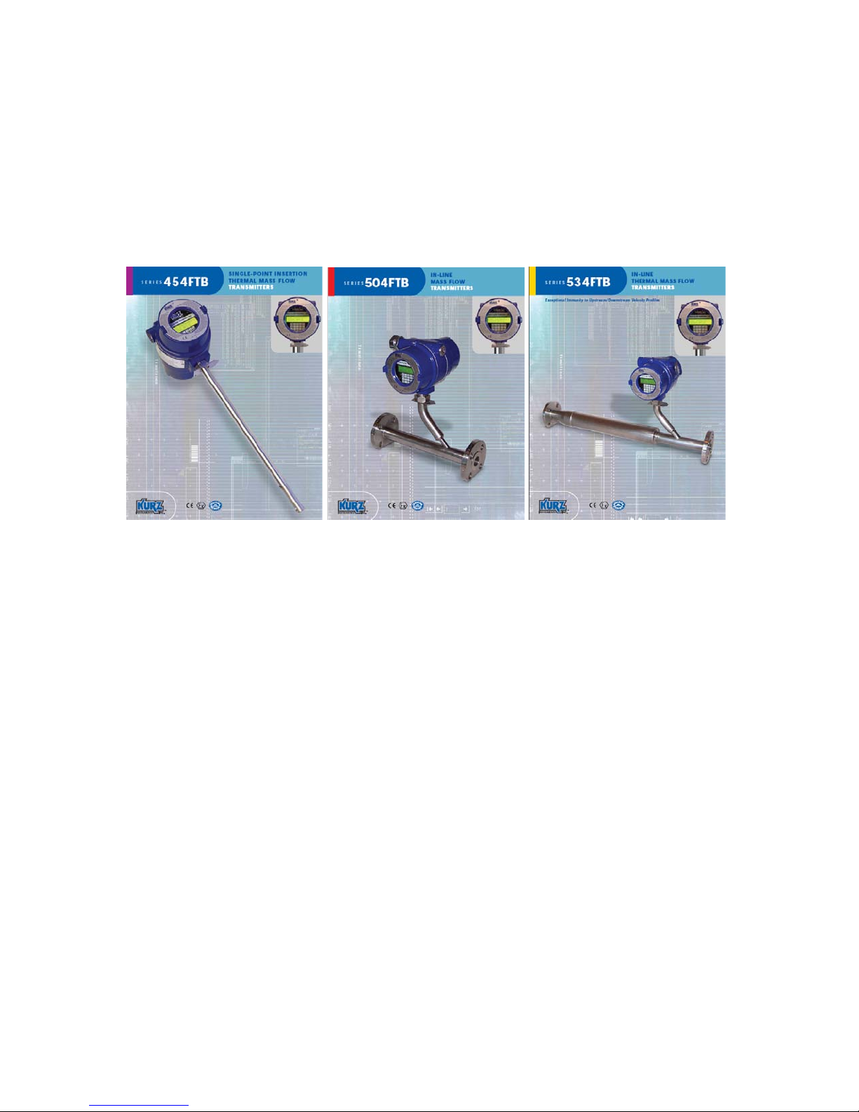
Models 454FTB, 504FTB, and 534FTB.
August 2010
For MFT B-Series Firmware 2.x
360208-F 454FTB, 504FTB, 534FTB 1
Kurz Instruments, Inc. 831-646-5911
+ Kurz Model # =
2411 Garden Road www.kurzinstruments.com
Monterey, CA 93940
The following information is an abbreviated list of what you need to do for your flow
meter to achieve maximum possible repeatability and accuracy. Most of the steps will be
required for all products. Please read this before you start.
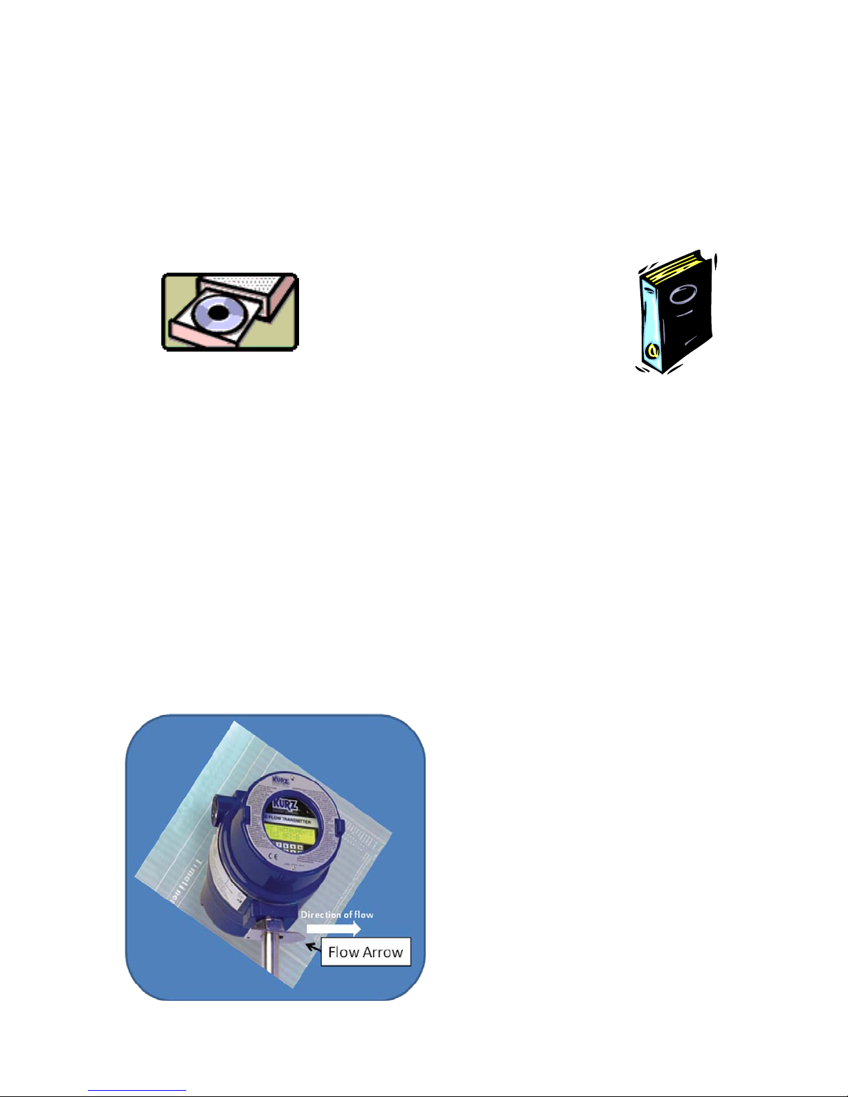
You will ultimately need to refer to the product manual, which is found on the attached
CD. Given the Model number of your product, you can find the manual you require.
Unpacking/Expected Conte nt
Your flow meter has been shipped to you with the following items. Please make sure you
have them and contact us if this is incomplete.
1. Flow meter, compare the packing list against your order.
2. Calibration certificate
3. Manual on CD
4. Menu Quick Lookup Card
Mounting of the equipment (se e guidel ines sheet)
You will need to remove the protective shipping covers from the sensor or flow body
before installing the unit. A thermal meter must have direct contact with the process fluid
to work. The meter will need to be mounted in accordance to safe design practice
accounting for the process pressures, corrosion, temperature and any potentially
hazardous area requirements. The electronics head needs to be in an accessible area so
you can do the wiring and access the local keypad/LCD if applicable. Some models have
remote electronics heads, which must be mounted/wired too. Most units can be
programmed with a Laptop portable
computer using the USB interface and PC
driver.
Each meter has a flow arrow mounted on
the outside of the enclosure that provides
a convenient mounting reference. The
flow arrow direction points in the
direction of the flow. For best results,
please carefully look over the installation
guidelines sheet for more on the sensor
placement criteria.
Insertion Meters must be mounted with a
compression fitting to the duct/pipe or
360208-F 454FTB, 504FTB, 534FTB 2

Kurz Instruments, Inc. 831-646-5911
2411 Garden Road www.kurzinstruments.com
Monterey, CA 93940
flange mounted then checked for leaks. Make sure the insertion depth is adequate to get
into the center line where the flow profiles are the most stable. The distance from profile
disruptions needs to be adhered to for the best repeatability/accuracy, see the guideline
sheet for more details. Check for process fluid leaks.
In-Line Meters have similar requirements for undisrupted straight runs except for the
534FTB line. Check for process fluid leaks.
360208-F 454FTB, 504FTB, 534FTB 3
Kurz Instruments, Inc. 831-646-5911
2411 Garden Road www.kurzinstruments.com
Monterey, CA 93940
360208-F 454FTB, 504FTB, 534FTB 4
>X
Vavg
Vs
CF(v) ?
CF(v)= Vavg/Vs
0.5 < CF(v) < 1.0
Kurz 4xx (454,etc.)
D
A ? (ft2 or m2)
A = D2π/4
d
L
L ? (ft, m), d ? (in)
SBCF= A/(A+12dL)
>5 D
CF(v)
v
x x x
x
0.7
1.0
Vs
ε < 2%
X = 40D
X = 20D
X = 15D
Less than two line
size changes
Less than two line
size changes

Kurz Instruments, Inc. 831-646-5911
2411 Garden Road www.kurzinstruments.com
Monterey, CA 93940
360208-F 454FTB, 504FTB, 534FTB 5
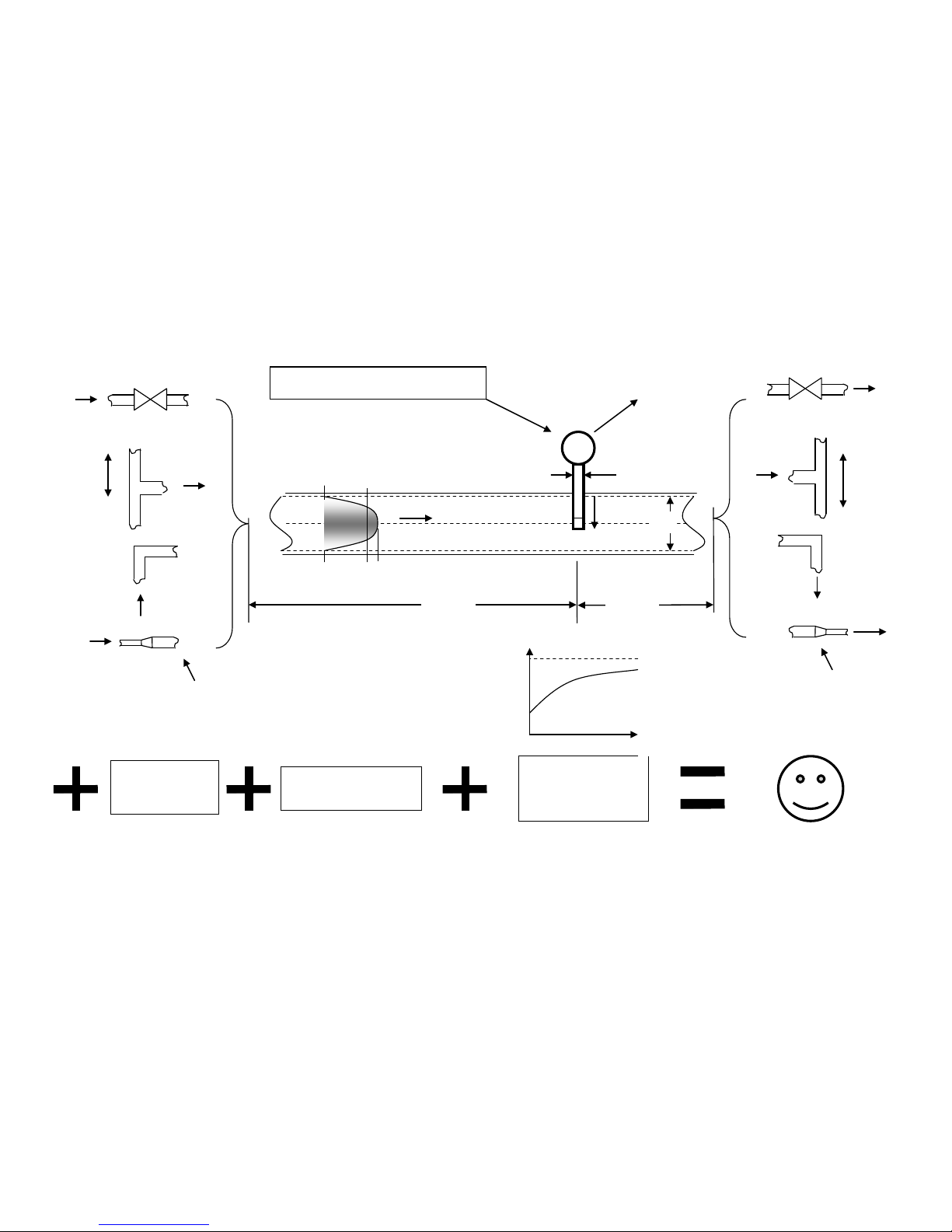
Insertion Meter Installation Guidelines
1. Mount Probe so its velocit y sensing element is centered in the duct/pipe. This location has the most stable flow reading. Note the flow arrow direction
points in the direction of the flow.
2. The upstream and downstrea m distance to flow profile disruptions from that of a straight pipe are “X” diameters upstream and 5 downstream. We have
chosen 2% maximum error from the baseline str a ight pipe calibration for the distance criter ia . Longer straight runs will reduce this error level. Here are
four example cases in order of their disruption to the flow:
a. Valves change the flow profile as they open and close so the sensor should not be located too close. The gate valve is the worst and the metering
valves are the best at reducing their flow profile changes between open and closed.
b. Branchin g joints also change the profile as the percentage of flow changes between the branches.
c. Elbows or direction changes will disrupt the long-run pipe profile. As this disruption settles down, the profile can wobble or move depending on
the flow rate. Several elbows in different planes wi ll impart a swirl that also imparts an error in the rea dings (flow is not straight on to the sensor)
and the upstream distance should be increased. The distance from elbows may be reduced if field calibrations are used. Double elbows in different
planes introduce swirl and need 50% more distance than a single elbow does.
d. A line size change will als o disrupt the pr ofile and can i ntroduce instability so this should be avoided unless you have more experience on how to
use this to your advantage. The distance from a line size change may be reduced if field calibrations are used.
3. The duct or pipe inside dimensions are used to determine the flow area of the meter. An are a wizard in the meter setup menu walks you through entering the
data and the meter will calculate the flow area.
4. The probe will block off some of the flow area and accelerates the velocity proportional to its area projected on to the duct/pipe cross section. This is known
as the Sensor Blockage Correction Factor (SBCF). You enter the insertion depth (L), which is measured from the end of the window to the duct inside wall,
in the meter setup menu and the meter will calculate the SBCF.
5. Field Calibration Data is the key to achieving accuracy for the insertion probe. Without this step you can have good repeatability but the absolute flow
number requires a reference flow measurement be taken at the same time you record the indicated display of the insertion meter. The correction factor
which is velocity dependent, CF(v), is defined as the ratio of True reading to Indicated reading. The basic calibration of the unit is a point velocity sensor.
To convert this to volumetric flow rate or mass flow rate requires the proper area and the average velocity, this is where the field calibration fits in. As the
field calibration method is quite long and technical, you are encouraged to do one of two things to achieve this:
a. Contract the field calibration with Kurz Instruments, Inc. or another reputable field calibration company.
b. Do it yourself if you have the experience or a test team at your disposal.
Common methods of doing reference method calibrations entail: duct traverses, tracer gas dilution method or the process Stoichiometry which requires support
from your process engineering group. Sometimes the correction factors can be entered based on an ideal duct profile model or a finite element analysis (FEA) or
computation fluid dynamics (CFD) program.
For more information on all the above, please refer to the full product manual provided on CD or at our website
www.kurz-instruments.com. Also see “Flow
Measurements 2
nd
ed.” Edited by D. W. Spitzer, ISA Press 2001. Chapter on Insertion Flow Measurements.

Kurz Instruments, Inc. 831-646-5911
2411 Garden Road www.kurzinstruments.com
Monterey, CA 93940
360208-F 454FTB, 504FTB, 534FTB 6
>X
Kurz 5xx (504 etc.)
>5 D
Kurz 534
0 D
0 D D X = 40D
X = 20D
X = 15D
ε < 2%
Less than two line
size changes
Less than two line
size changes

Kurz Instruments, Inc. 831-646-5911
2411 Garden Road www.kurzinstruments.com
Monterey, CA 93940
360208-F 454FTB, 504FTB, 534FTB 7
In-Line Meter Installation Guidelines
1. Mount the Meter so its sensing element meets the upstream and downstream requirements of that model:
a. Kurz Models 504 etc. all need “X” inside pipe diameters upstream and 5 downstream of the sensing element to ensure a
repeatable and accurate reading within 2% of the initial calibration. Double elbows in different planes introduce swirl and
need 50% more distance than a single elbow does. Longer straight runs will reduce this maximum error. Any
discontinuity in the straight pipe flow profile will change the reading compared to its calibration conditions. The data were
initially calibrated using long straight runs with short close-coupled pipe flanges that minimize the line-size discontinuity.
In many applications, field calibration data can be used to reduce the upstream and downstream requirements.
b. Kurz Model 534 have a built in flow conditioner and all the straight run it needs so there is no upstream or downstream
straight run requirements to achieve the rated accuracy.
2. If the process fluid is hot or cold compared to the ambient air, then insulation around the pipe/meter upstream for about 30
diameters or more will help reduce thermal gradients in the process fluid near the sensor to avoid these errors. As the temperature
is changed, the thermal inertia of the piping will cause a lag in the thermal profile so a longer stabilization time will be required.
For more information on all the above, please refer to the full product manual provided on CD or at our website www.kurzinstruments.com

Kurz Instruments, Inc. 831-646-5911
2411 Garden Road www.kurzinstruments.com
Monterey, CA 93940
360208-F 454FTB, 504FTB, 534FTB 8
 Loading...