

Page 1

Installation & Operation Guide
P/N DL640-95, REV C
Model:
DL640
DL430
CT640
CT430
Page 2

KURT INDUSTRIAL PRODUCTS
VERVIEW OF
O
"640, 430" VISES
The new DoubleLock vises from Kurt include improvements that simplify
its operations. Please read this entire instruction manual to fully understand the
new features of the DoubleLock vise. You will find modifications have been
made that are different from the past DoubleLocks.
Kurt's new DoubleLock has a design that fits current user needs and meets
their expectations of a simple, functional vise. The new DL640, DL430,
CT640, and CT430 maintains the 3", and 4" opening, same bed height with the
DL430 and DL640, and same accuracy and has superior features over past
Kurt DoubleLock style vises. Listed are the re-designed features of the new
DoubleLock vise. Please refer to the page listed on index for setup instructions.
1. Clutch design- The new clutch has a recoil spring attached to the
clutch. It's designed to return the clutch back into the correct position
automatically. It resets into the correct position every time the vise jaws
are opened. No more timing problems ever!
2. New Holding Block- The function of the holding block is to give the
end user the adjustment features to clamp dissimilar size parts and
provides front or back part spring loaded pre-clamping. The new
holding block is completely self-adjusting that includes a double preload. This means the user may clamp one part first, front or back station
before loading the second part. No need to adjust for dissimilar parts.
Also included is a pre-load range adjustment nut that will give the user
the option to choose how much pre-load range they need. (.010 min to
.150" max) When setting to minimum range, this will reduce the amount
of handle turns needed when opening or closing the Vise.
NOTE
: This vise has been assembled to factory settings and no further
PLEASE
adjustments are required. The holding block pre-load and pre-load
adjustment nut are new features of this products design and allows
adjustment for a specific setup. Please see "Holding Block Pre-Load"
and "Pre-Load range adjustment nut" setup sections in this guide.
New Overall length
3.
and 18.5" (17.5" with internal hex) on the DL430.
- DL640 is 22.5"(21.5" with optional internal hex),
1
Page 3

4. New Chip Guard system- The center clamping area is fully covered
100% of the time. Note: The stationary chip guard may need to be
removed when the vise is used with the optional conversion kit. See
conversion kit assemble section.
5. New Locating hole patterns- The clamp down mounting holes that
will fit a standard 2" grid pattern found in sub-plates available through
several industrial suppliers. The base includes four precision 5/8" holes
in the bottom for accurate re-location. Also available are two 16mm
holes that will fit a 100mm and/or 200mm grid patterns found in metric
sub-plates. (See locating and mounting hole sketch for reference). The
use of Sine Keys would also provide mounting the Vise to machine
tables with key slots if needed.
New Stationary Jaw
6.
- The DoubleLock vise has a precision locator for
accurate repeatability. This gives the Stationary Jaws exact relocation
when used with interchangeable Stationary Jaw setups or re-setup from a
convertible model.
7. Convertible models- When the DL640 or DL430 is needed for a single
large part clamping, the maximum opening is 10.69" to a minimum of
2.69", and 8.20" to 2.1" on the DL430. This is a continuous travel
opening.
Kurt offers quick change one-sided Aluminum carvable Moveable Jaws for
conversion into a carvable vise. Optional internal hex is also available. (Contact
factory for information and costs).
These important features and functions make Kurt's new DoubleLock an
accurate, durable, affordable "user friendly" vise. Combined with the industries
only ten (10) year warranty. The Kurt DoubleLock vises fills all your CNC
WorkHolding needs.
2
Page 4

DOUBLE LOCK
INSTALLATION AND MOUNTING INSTRUCTIONS
INSTALLATION
The Kurt DoubleLock Vise offers two clamping stations. This vise is ideal
for clamping parts of the same size or dissimilar size, and can perform first
and secondary operations simultaneously. It is packaged to prevent any
damage to its components. Please inspect the vise carefully for any shipping
damage and, if necessary report it to your carrier.
After inspection, follow these steps to install your DoubleLock Vise:
1. Position the vise on your machine table, pallet or sub-plate using the
Precision bored holes located on the bottom of the vise for alignment.
See figure 2 on page 4 for locating hole patterns.
2. A couple of options to mount the vise in place. One option is to use
external clamps on the clamp groove on each side of the vise. NOTE: To
reduce any possible deflection while clamping parts, mount external
clamps on each side towards the center of the vise in the clamp grooves.
A preferred option would be to use the eight cap screw holes through
the vise bed. To gain access to the holes, open both stations to the full
opening. Remove the Jaw Plates mounted to the center Stationary Jaw
and two Moveable Jaws sets. See figure 1, page 4 for mounting hole
pattern. Note: The four mounting holes toward the center Stationary is
required when using this mounting option. The four mounting holes
under Moveable Jaws are an addition to mounting with this setup.
If desired both mounting options may be used.
3
Page 5

4
Page 6

Holding Block Pre-load setup
*PRE-LOAD PARTS.
(* Is defined as ability to clamp one part first with limited pressure before
second part is installed.)
Caution: Pre-Load places only enough spring pressure to hold one part
and are not intended to clamp part for machining. Both stations must be
clamped to achieve clamping pressures.
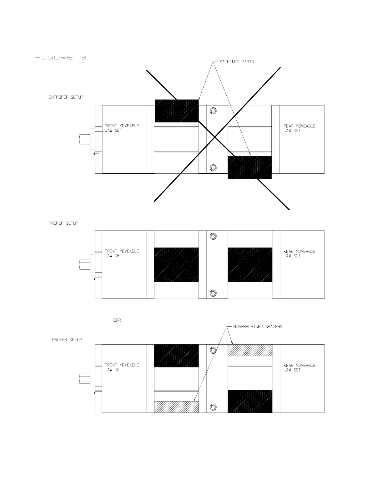
NOTE 1: In all jaw settings, unless both parts are the same size, the Widest
part must always be mounted in the Rear Jaw Set. See figure 3 page 6.
NOTE 2: Same size part, Pre-load must be setup to clamp front part.
Horizontal vise position
(reference sketches on page #6)
1. Open both Moveable Jaws sets to accept part being clamped.
2. Place one part into each station and close.
3. Open only enough to release pressure from each parts.
4. Remove the part that is planned to be pre-loaded. (Vertical vise position
see caution below)
5. Leaving the opposite part in the vise, begin to close allowing the Holding
block to slide 3/16" minimum. See figure 4 page 6.
6. Begin to open and both Movables will open.
7. Remove all parts in the vise.
8. Your Pre-load is now set.
9. Place part to be Pre-loaded in and begin to close until part is clamped.
Install opposite part and clamp.
Vertical vise position
Caution: In this position, the horizontal vise position setup is used but we
recommend to always setup with the pre-load in the top station. The
Stationary Jaw is a fixed stop where the bottom Moveable Jaw will have
movement and part could appear to be pre-loaded and part could move
causing personal injury. Please use caution at step #4.
5
Page 7

elease rear part
st.
ont part
st.
Front Jaw Rear Jaw
This setup will always clamp
front part first . Once set it will
fir
r
Front Jaw
Front Jaw
Rear Jaw
This setup will always clamp rear
part first . Once set it will release
fir
fr
Rear Jaw
6
Page 8

Pre-Load rangeAdjustment Nut
Refer to sketch below for direction of adjustment
To remove Pre-Load range (Reducing the amount of turns of the handle
when clamping or unclamping parts).
1. Loosen but do not remove the (socket head set screw) on top of Holding
Block.
2. With the use of a spanner wrench, begin to turn the Adjustment Nut
clockwise. Each full turn will reduce Pre-Load amount by appoximitly
.04. NOTE: Maximum reduction is .100/.150 or approximately 3-3/4
turns of the Nut. NOTE: If adjustment Nut turns to a complete stop
before the 3-3/4 turns, maxim um reduction range is complete.
3. Turn counterclockwise Aligning the first slot on the Adjustment Nut with
the SHSS and tighten.
To add Pre-Load range (Increase the amount of turns of the handle)
1. Loosen but do not remove the SHSS on top of the Holding Block.
2. With a spanner wrench turn the adjustment nut counter clockwise until
threads on the Adjustment Nut begin to show.
3. Align the slot on the Adjustment Nut with the SHSS and tighten.
7
Page 9

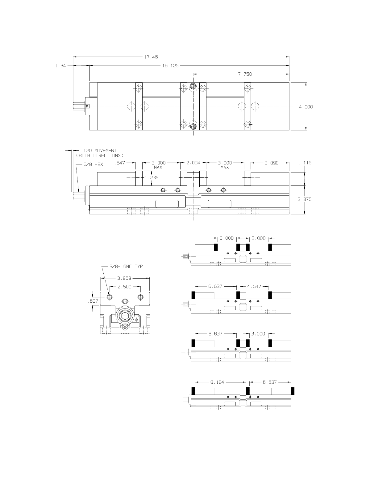
Conversion Kit Assemble - DL640, DLM640 / DL430, DLM430
Refer to Conversion Kit Sketch on this page for setup preference.
CAUTION
USE CAUTION WHEN HANDING CHIP GUARD MATERIAL. EDGES AND
CORNERS ARE SHARP AND MAY CAUSE PERSONAL INJURY IF NOT
HANDLED PROPERLY.
1. Before beginning setup, clean the backside of the Rear Moveable Jaw set and the
Body surface opposite the handle where Conversion Plate will be mounted.
2. Remove Stationary Jaw. Note: Stationary Jaws widths are fitted to each body and
are "letter" stamped on the side of the Stationary Jaw and in the Body keyway.
When reinstalling the letter stamped must match the body for proper fit.
3. Mount the Conversion Plate to the Body using the provided Socket Head Cap
Screws (SHCS) and tighten.
4. Open the vise completely turning the screw counter clockwise until the back
Moveable Jaw set is at maximum travel.
5. Install SHSS and tighten to the Moveable Jaw set.
6. Depending on your setup, custom cut Chip Guard maybe required. Provided with
Conversion Kit is (2) standard length Chip Guard material that maybe used.
Contact factory for replacement or additional Chip Guard material. Note
Maximum opening and closing.
Examples of some conversion setups. All dimensions are referenced in inch.
NOTE: This vise is not to be used as a self-centering Vise
DLC640-INST.
04/26/00 rev 1
8
Page 10

General Cleaning/Maintenance Procedure
6/18/98 rev 1
DoubleLock Model #
DL640, CT640, DL430, CT430 (metric included)
TO ASSURE PROPER USAGE AND CONTINUOUS SERVICE OF
YOUR DOUBLELOCK VISE, IT IS IMPORTANT TO REGULARLY
CLEAN ANY MATERIAL BUILD UP THAT MAY HAVE OCCURED.
LITTLE OR NO MAINTENANCE COULD RESULT IN POOR VISE
FUNCTION.
A. DISASSEMBLY INSTRUCTIONS
1. Open both Moveable jaws to the maximum openings.
2. Loosen the setscrews in the backside of both the Front and Rear Movable
Jaw sets. Loosen only enough to allow Movable to pivot up off the Nut
and Screw assembly. (approx. 6 turns). NOTE: The Chip Guards are
attached to the Movables. Take care when removing Movables. Note:
Once the Movable Jaws have been removed, there is a segment shaped as
a half Ball in the cavity. Be careful not to mis-place while cleaning.
3. If maintaining more than one vise at a time, the Stationary Jaw is made
specifically for the base it is in. Note stamped letters on the side of the
Stationary and the inside of the hold down slot in body for re-assembly
reference.
4. Remove the (2) SHCS (Socket Head Cap Screw) holding the Stationary
Jaw and remove jaw.
5. Remove any remaining Chip Guards.
6. Clean disassembled parts as needed.
7. Note: The Nut & Screw assembly should not have to be removed if
regular maintenance is done. If required to remove for additional cleaning
remove the Button Head Cap Screw on Handle end of the V ise bed and
slide Screw and Nut assembly out. Caution: Disassemble of the Screw
and Nut assemble may result in improper function once re-assembled.
Important timing is involved w ith the internal springs. Please contact
factory for requirements.
B. ASSEMBLY INSTRUCTIONS
1. If Nut and Screw assemble was removed refer to sketch on page 10 for
Nut timing. Slide Screw and Nut assemble into the Body. Install Button
Head Cap Screw and tighten.
9
Page 11

2. Before placing the (2) Movable Jaws over the Nuts make sure the
segments are in the inside cavity using grease to hold them in place and
for lubrication.
3. Spread a small amount of oil to the bed of the vise where the Moveable
Jaws will be installed.
4. Place the Movable Jaw starting with the side with (2) holes into the
center way. In a slide motion, slide Movable Jaw over the Nut allowing
the Movable to drop over the Nut. NOTE: The 45-degree angle of the
Nut should be on the flat surface of the Movable Segment.
5. Snap the Chip Guard onto the pins underneath each Moveable. Note:
May need to lift up slightly to catch the pins with the Chip Guard.
6. Tighten the SHSS in the Movable until it makes contact with the Nut.
Turn back approximately ¼ turn. IMPORTANT: THIS SHSS SHOULD
NOT BE COMPLETELY TIGHT. THIS WILL ALLOW MOVEMENT
OF THE MOVABLE JAWS. SEE SKETCH ON NEXT PAGE.
7. Place the Stationary Chip Guard into place.
8. Install the Stationary Jaw and tighten in place using the (2) SHCS.
9. To seat the segments in the Movable Jaw, tighten vise with supplied
handle, and then open vise until close to full opening. If needed tighten
the SHSS in the back of Movable Jaws then loosen approxim a tely ¼ turn.
10. Vise is now ready for use.
10
Page 12
DL430
11
Page 13

DL640
12
Page 14

PRECAUTIONS
When using the DoubleLock Vise in production, remember the following
points:
• Never use this vise as a Self Centering Vise.
• See figure #3, page 14. Never
clamp parts opposite from each other.
• Always clamp directly across from each other or use a spacer to even
clamping pressure points.
• Use the Handle provided or Torque Wrench with your vise. The rated
clamping forces are obtained with these handles. Never
use an extension
or strike the handle with a hamme r. This will cause damage to the thrust
bearings.
• When using parallels or Step Jaws, select a size that keeps the BOTTOM
of the clamped part at or below the top surface of the Movable Jaw.
Clamping above this surface could result in Jaw lift and loss of accuracy.
• Never use a hamm e r, blunt object, or "cheater bar" in assisting when
clamping parts in the vise. Damages to the Thrust Bearing assembly, and
seals may accrue.
• Always use the handle provided, handle equivalent, or torque wr ench.
• Avoid using an impact wrench. Some impact wrenches cause internal
“shock” on moving components and increasing the wear significantly. If
an impact wrench is used, avoid rapid movement. Never use the impact
wrench to tighten the part. This increases the clamping forces above the
product capabilities and causes stress in areas not intended to except
stresses. A controllable torque impact wrench is acceptable only when
clamping forces needs to be consistence. Avoid over torquing.
• Clamp parts to the lowest position possible. Part nesting at the vise base
increases clamping forces and decreases the possibility of part distortion.
• Always clamp the part with the part at or near center of the vise width.
Clamping a part beyond center may cause inconsistent part clamping
pressures.
13
Page 15
14
Page 16

CUSTOMER SERVICE
For additional information or question about your vise, Please contact K urt
Manufacturing at 1-800-328-2565 between the hours of 7:30 a.m. and 4:30
p.m. Central Standard Time.
REPLACEMENT PARTS
Contact your Kurt Manufacturing representative for a complete list of
DoubleLock replacement parts and pricing. Your representative can also
provide you with a Kurt Manufacturing Product Catalog containing all
products and accessories for your Workholding needs.
FACTORY CONTACT
Kurt Manufacturing Company
1325 Quincy Street N.E.
Minneapolis, MN 55413
Phone: 612-572-4424
Toll free: 1-800-328-2565
Fax: 612-623-3902
Web site: www.kurt.com
15
Page 17

REVISION HISTORY
REVISION A
JULY 1998
COPYRIGHT 1998 KURT MANUFACTURING
THIS DOCUMENT IS CONFIDENTIAL AND IS THE PROPERTY OF KURT
MANUFACTURING. IT MAY NOT BE COPIED OR REPRODUCED IN ANY WAY
WITHOUT THE EXPRESS WRITTEN CONSENT OF KURT MANUFACTURING.
KURT MANUFACTURING INTENDS TO AND IS MAINTAINING THE WORK AS
CONFIDENTIAL INFORMATION. KURT MANUFACTURING ALSO MAY SEEK
TO PROTECT THIS WORK AS AN UNPUBLISHED COPYRIGHT. IN THE EVENT
OF EITHER INADVERTENT OR DELIBERATE PUBLICATION, KURT
MANUFACTURING INTENDS TO ENFORCE ITS RIGHTS TO THIS WORK
UNDER THE COPYRIGHT LAWS AS A PUBLISHED WORK. THOSE HAVING
ACCESS TO THIS WORK MAY NOT COPY, USE OR DISCLOSE THE
INFORMATION IN THIS WORK UNLESS EXPRESSLY AUTHORIZED BY KURT
MANUFACTURING.
PLEASE READ AND OBSERVE THE FOLLOWING SAFETY PRECAUTIONS
FOUND THROUGHOUT THIS MANUAL.
CAUTION
FAILURE TO OBSERVE MAY CAUSE MINOR OR MODERATE PERSONAL
INJURY OR DAMAGE TO THE EQUIPMENT.
CAUTION
USE CAUTION WHEN HANDING CHIP GUARD MATERIAL. EDGES AND
CORNERS ARE SHARP AND MAY CAUSE PERSONAL INJURY IF NOT
HANDLED PROPERLY.
 Loading...