

Kuppersbusch TKD, TKD 988.1, TKDEM 988.1 Instructions For Use And Installation Instructions
Page 1

BEDIENUNGSANWEISUNG
mit Montageanweisungen
Instructions for use and installation instructions
Instructions d’ utilisation et avis de montage
Gebruiksaanwijzing en montagehandleiding
Istruzioni di uso e di montaggio
Instrucciones de uso y de montaje
TKD/TKDEM 988.1
53 82 91 G61
Page 2

12 GKS 324.0/GKS 644.0 G51
For your information...
You should carefully read the information in this manual before you use your
cooker hood. Here you will find important notes concerning safety and how to
use, look after and service your appliance so that it enjoys a long service life.
Should a fault arise, please first consult chapter “What to do if trouble occurs...”. You can often remedy minor faults yourself and thus save unnecessary service costs.
Always keep these instructions in a safe place and pass them on to new
owners for their information and safety.
The following symbols are used in this operating manual:
=
The warning triangle draws your attention to possible risks for your
health or damages that might be caused at your appliance.
F
Here you will find information and notes.
Conditions of guarantee
The conditions of guarantee applicable for this product are subject to those
published by the representative in the relevant country.
Details regarding same may be obtained from the dealer from whom the
appliance was purchased. For claims under guarantee the sales receipt must
be produced.
Content
Safety instructions . . . . . . . . . . . . . . . . . . . . . . . . . . . 13
For connections and functions
For operating your cooker hood
For operating the hood with stoves and
heating appliances with a naked flame
General advice for use. . . . . . . . . . . . . . . . . . . . . . . . . 13
Your appliance at a glance. . . . . . . . . . . . . . . . . . . . . . 14
Using the hood . . . . . . . . . . . . . . . . . . . . . . . . . . . . . . 14
The power supply of the control panel
Before using the hood the first time
Remote control (optional accessory)
Switching the lighting On/Off
Switching on the ventilation
Changing the ventilation setting
Switching the ventilation off
The intensive button
Activating the automatic delayed stop
Cleaning, care and maintenance. . . . . . . . . . . . . . . . . . 15
Cleaning the hood
Cleaning the metal fat filters
Changing the activated charcoal filter (in recirculation mode)
Replacing a halogen lamp
Changing the battery of the remote control
What to do if trouble occurs... . . . . . . . . . . . . . . . . . . . 16
Rating label
Installation preconditions . . . . . . . . . . . . . . . . . . . . . . . 16
Scope of delivery
Dimensions for installation
Walls suitable for mounting/suitable fixings
Electric connection
Possible extraction versions
Chimney attachment and length of chimney
Installation . . . . . . . . . . . . . . . . . . . . . . . . . . . . . . . . . 17
Unpacking of the components
Screwing the switching unit to the hood body
Mounting a steel rear panel (optional)
Marking the drill holes
Installing the hood body and chimney attachment
Recirculation mode only: adjust deflector and ducting
Extraction mode only: attach the ducting
TKDEM 988.1 only
Electric connection
Mounting the chimney
Inserting the filters
Function testing of the hood
Guideline for extraction paths. . . . . . . . . . . . . . . . . . . . 20
Extraction path through the walls
Extraction through the kitchen ceiling and roof
Extraction into an existing exhaust shaft
Please note:
Page 3
GKS 324.0/GKS 644.0 G51 13
Safety instructions
For connections and functions
■ Maintenance and repair work may only be carried out by an authorised
technician in accordance with the applicable safety regulations. Work which
has been performed improperly can endanger your safety.
■ Extraction appliances must not be connected to smoke or fume chimneys
or to shafts used for ventilating rooms where stoves have been installed.
Before extracting fumes into a smoke or fume chimney which is not in use,
please obtain approval from your local chimney sweep. When extracting
fumes, please observe the official regulations.
■ The minimum distance between the cooker hood and the cooker is
650 mm.
■ For cleaning and maintenance work the hood must be deactivated by
switching off the household fuse.
For operating your cooker hood
■ The fat filter must be cleaned regularly. There is a danger of fire if the ap-
pliance is used with a saturated fat filter!
■ Only use the hood when the fat filters have been installed.
■ Never flambé dishes under the cooker hood!
■ Ignited rings of gas cookers and gas hobs must always be covered by pots
or pans.
■ Keep an eye on deep-fat fryers while in operation. Fat and oil which ignites
due to overheating can set fire to the cooker hood.
■ The fume trap should not bear excessive or one-sided loads. If the glass
breaks, there may be a danger of injury from falling pieces of glass!
For operating the hood with stoves and
heating appliances with a naked flame
This relates, for example, to gas, oil or coal-fired heating appliances,
continuous flow heaters and hot water tanks: If the cooker hood is operated
in extraction mode, such appliances may no longer have sufficient air required
for combustion and there is a danger of intoxication or explosion!
Operation is perfectly safe if the cooker hood and the stove are being used
simultaneously in rooms where a negative pressure of 0.04 mbar is not
exceeded. This ensures that the fumes from the stove are not sucked back
into the room.
This can be achieved if there are non-airtight openings in windows and doors,
ventilation wall boxes (supplying/extracting air) or other technical
devices, e. g. interlock devices so that a sufficient supply of combustion air
can flow back into the room.
When assessing the ventilation requirements, the ventilation system of your
entire home must always be taken into account. This means, for example, the
above regulations for operating cooking appliances (e.g. hobs and gas cookers)
are not applied. If in doubt, please consult your local chimney sweep.
■ If the cooker hood is only used in recirculation mode - with activated
charcoal filter - there are no restrictions on operation.
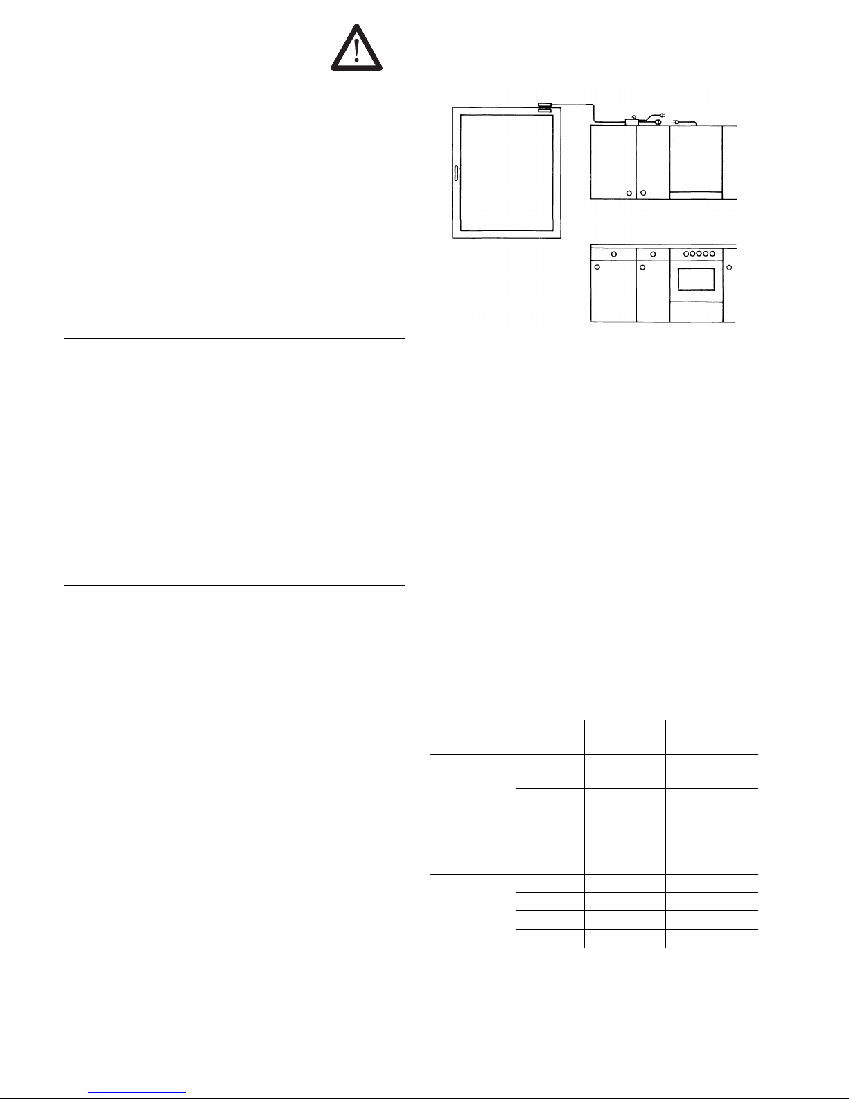
Example of how to use the cooker hood and the stove in
complete safety:
■ A switch at the window prevents the cooker hood from being operated when
the window is closed.
General advice for use
Remember that the ventilation problem in the kitchen is often not solved
merely by installing a cooker hood. For optimum effect and maximum
ventilation efficiency the cooker hood requires a sufficient supply of air from
the correct sources. Disappointing performance and the development of loud
noises are almost always the result of planning or operating errors.
Example:
■ Insufficient supply of fresh air
Result: The speed of the ventilation motor increases, the air capacity
decreases and the noises become louder.
Solution: Ensure that there is an adequate supply of fresh air through structural measures or by opening the window when the cooker hood is in operation.
■ Saturated filters
Result: The air capacity of the cooker hood decreases and the fumes are
insufficiently cleaned.
Solution: Clean the filters regularly before the air capacity decreases.
in extraction
mode
in recirculation
mode
Appliance
switch on
appliance
on starting
cooking
on starting
cooking
switch off
appliance
approx. 5 min.
after finishing
cooking
approx. 15 min.
after finishing
cooking
Position of door open closed
window closed open
The room air is
cleaned of
humidity X -heat X -fat X X
odours X X
Page 4

14 GKS 324.0/GKS 644.0 G51
Your appliance at a glance
Using the hood
=
Please observe the safety instructions on page 13.
The power supply of the control panel
=
Always push the glas fume screen in, when the hood is not operated.
The operating fascia at the glas fume screen is not directly connected to the
control unit of the hood. It is supplied with the current required for the contact
to the control unit from an accumulator that is charged as long as the glas fume
screen is closed (due to the contact with the transformer at the hood body).
If the hood shows no response when you press the buttons after having pulled
out the glas fume screen, the accumulator has been discharged. Push the glas
fume screen in so that the accumulator is charged. In the meantime, the hood
can beoperated with retracted glas fume screen. The accumulator is fully recharged after approx. 8 hours (without hours of use) and the hood can be
operated with pulled-out glas fume screen again.
Before using the hood the first time
– Please clean the cooker hood before using it for the first time as described
in “Cleaning, care and maintenance” on page 15.
=
Leave the glas fume screen in the retracted position for at least 8 hours
after installation so that the accumulator of the control panel can be recharged.
If the hood is not activated when the glas fume screen is pulled out,
please operate the hood with retracted glas fume screen (see “The power
supply of the control panel” above).
Remote control (optional accessory)
The remote control serves for switching on and off the lighting and ventilation
and for changing the ventilation setting. All other functions of the hood must
be activated or deactivated directly at the control panel.
Switching the lighting On/Off
– Press the button ! to switch the halogen lamps on.
– Press the button ! again to switch the halogen lamps off.
Switching on the ventilation
– Press the button # . The ventilation is switched on with the setting that
has been activated when the hood was switched off.
Changing the ventilation setting
The hood can be switched to four ventilation settings (1 to 4).
– Press the
+ button (or ) to increase the ventilation setting.
– Press the
- button or ( ) to reduce the ventilation setting.
Switching the ventilation off
– Press the button # when the ventilation is running.
The intensive button
F
The intensive button cannot be activated via the remote control. Use the
remote control to increase the ventilation setting step-by-step until setting
“4” is reached.
If the intensive button is pressed, the cooker hood is switched to the maximum
ventilation setting (“4”).
– Press the button 8 . The chiffre “4” is indicated in the display.
Activating the automatic delayed stop
F
If you have finished cooking and wish to operate the hood for another
10 minutes by using the automatic delayed stop, already push in the glas
fume screen, if possible, so that the accumulator of the control panel can
be immediately recharged.
The automatic delayed stop can be activated with any ventilation setting. It
switches the cooker hood completely off (ventilation and lighting) after 10 minutes.
– Press the button # , until a small dot is flashing next to the chiffre.
Chimney
Glas fume screen
Control buttons
Transformator
Metal fat filter
Halogen spotlights
V
enting slots (in re-
circulation mode)
Hood body
Control buttons at the glas fume screen
Buttons at the remote control
A Display
B Ventilation on/off
C Lighting on/off
D/E Ventilation setting
F Intensive button
Page 5

GKS 324.0/GKS 644.0 G51 15
Cleaning, care and maintenance
=
Caution! For repair work or cleaning the inside of the hood, switch off
the household fuse or pull out the mains plug.
=
Do not use any scouring agents or aggressive cleaners.
Cleaning the hood
Control panel
– Carefully wipe the control panel now and again with a soft cloth which is
free of fluff. Make sure that no water penetrates into the slots between the
control buttons.
Glass surfaces
– Clean the glass surfaces with a damp cloth and a little hand detergent or
one of the usual glass cleaning agents.
Stainless steel parts
– Clean stainless steel parts with a damp cloth and a little hand detergent.
Then wipe dry.
– Use one of the usual stainless steel cleaning agents from time to time.
Remote control
=
The remote control must not be put into water!
– Only clean it with a damp cloth and, if required, with a little hand detergent.
Cleaning the metal fat filters
Important! If you use the hood in recirculation mode, you must also renew
the activated charcoal filter roughly about 120 h of use. You can obtain original filters from your dealer or direct from KÜPPPERSBUSCH.
Filter saturation indicator
=
Saturated fat filters reduce the performance of the hood and may ignite
due to naked flames or great heat.
Both filter inserts must be simultaneously cleaned when the letter “F” is
indicated in the display (after 30 operating hours).
– Switch off the filter saturation indicator by pressing the button 8 when the
ventilation is switched off until the “0” is no longer displayed.
Cleaning the metal filters
– Hold each metal filter by the
handle and push back lightly. To
remove pull down out of the
bracket.
– Clean the metal filters in the
dishwasher or wash by hand
with a mild detergent. Rinse
well and dry before refitting.
– Recirculation mode: Change the
activated charcoal filter,
whenever nessesary.
– To refit the filters, place in the
slot at the rear and push up.
They will then click into place.
Changing the activated charcoal filter (in recirculation mode)
F
The activted charcoal filter is only required in the recirculation mode. It
must not be used in the extraction mode.
Filter saturation indicator
After approx. 120 hours of use, the letter “F” flashes in the display of the
control panel. The activated charcoal filter cannot be cleaned or regenerated.
It must be replaced.
– Switch the saturation indicator off by pressing the button 8 when the
ventilation is switched off until the “0” is no longer displayed.
Changing the activated charcoal filter
– Remove the metal fat filters (see “Cleaning the metal fat filters”) and clean
them.
– Push the activated charcoal filter to
the rear and take it out by moving
it downwards.
– Install the new activated charcoal
filter by inserting the two metal noses into the recesses at the rear side.
– Insert the activated charcoal filter
into the bracket at the front so that it tightly fits.
Replacing a halogen lamp
=
Caution! The halogen lamps become very hot after being in use for some
time. Therefore, the lamps should be changed when they have cooled
down.
=
Only replace the halogen lamps with lamps of the same type.
F
Do not grip the halogen lamps with your bare hands. Finger marks burn
into the lamp glass and reduce the light intensity and service life of the
lamps.
– Remove the lamp cover from the bracket by turning it in a clockwise direc-
tion.
– Remove the halogen bulb from its socket.
– Hold the new bulb with a cloth (e.g. tissue) and
push into the socket.
– Reinstall the cover.
Changing the battery of the remote control
– When the hood no longer reacts to the
buttons on the remote control, you
probably have to change the battery in the
remote control.
– Remove the cover of the remote control.
– Undo the battery connections.
– Remove the battery, insert a new one
(9V E-block) and connect it.
– Close the cover again.
Page 6

16 GKS 324.0/GKS 644.0 G51
What to do if trouble occurs...
=
The cooker hood may only be repaired by an authorised technician.
=
For repair work the appliance must be disconnected from the power supply by pulling out the mains plug or unscrewing the household fuse.
You can deal with some problems that occur yourself. First check whether
there has been any operating error. Repairs during the guarantee period are
not free of charge, when they are caused by operating errors or non-observance of the following instructions:
Rating label
The rating label can be seen when you have removed the fat filter or the
activated charcoal filters. Please make a note of the following data on the
rating label before or while installing the cooker hood in case you have to
consult our Customer Service:
Installation preconditions
=
The cooker hood may only be installed and the electrics connected by a
qualified technician. Pay attention to the notes on safety on page 13!
=
Danger! For all installation and maintenance work the cooker hood must
be disconnected from the power supply. As the mains plug is no longer
accessible after installation, you must switch off the relevant household
fuse.
Scope of delivery
TKD 988.1:
Hood body with extendable glass fume trap, motor housing and switching unit
Chimney, recirculated air deflector, reduction piece (150-125 mm).
Fastening material and drill hole template, instructions for use and installation.
TKDEM 988.1:
Hood body with extendable glass fume trap, motor housing (without motor and
fan) and switching unit, chimney.
Fastening material and drill hole template, instructions for use and installation.
Dimensions for installation
Walls suitable for mounting/suitable fixings
=
The fitter is always responsible for selecting the correct fastening material. The fastening method must be suitable for the weight of the hood.
Please also observe the “Guideline for extraction paths” on page 20.
The cooker hood can be mounted directly on the wall or on a steel rear panel.
■ The enclosed dowels and screws are suitable for walls made of perforated
bricks or concrete bricks which are 20 mm thick.
■ For solid concrete walls you must use special concrete dowels from a
specialist store.
■ For solid wooden walls you must use wood screws of sufficient thickness
and length.
Problem Cause Remedy
It is not possible to switch
off the cooker hood.
Electronic component
is defective.
Pull out mains plug or
switch off fuse.
Reconnect or switch on
again after approx. 2 minutes.
In case the fault has not
been reset, call the Customer Service.
=
Pull out mains plug or
switch off fuse.
Breakdown of the
microcontroller
A lamp does not work. Lamp defective. Replace lamp.
Hood does not work when
fume trap is extended.
Accumulator of the
operating fascia is
discharged.
See “The power supply of
the control panel” on
p. 14.
Performance of the cooker hood is reduced.
Filters are very
clogged.
Clean the filters.
“F“ in the display. No defect. See “Cleaning the metal
fat filters” on page 15.
Flashing “F” in the
display.
No defect. See “Changing the activa-
ted charcoal filter (in recirculation mode)” on p. 15.
Remote control (optional)
does not work.
Battery discharged or
not inserted.
Insert a new battery. See
p. 15.
Serial number:
Model designation:
Recirculation mode
Extraction mode
Page 7

GKS 324.0/GKS 644.0 G51 17
Electric connection
The hood is fitted with a normal mains plug and there should therefore be a
socket outlet (230 V alternating current) in the chimney path. The associated
dimensional drawing is to be found in the next chapter “Possible extraction
versions”.
Possible extraction versions
– Determine the position of the socket outlet and, if required, the position of
the exhaust hole, by means of the respective dimensional drawing.
Recirculation mode
There are no further preconditions for the customer, as there is no extraction
path through the wall or ceiling. The socket outlet can be located within the
marked area.
Extraction path to the rear
There must be an exhaust channel 150 mm in diameter through the wall
inside the marked chimney surface.
Extraction path upwards
There must be an exhaust channel 150 mm in diameter in the ceiling above
the installation point of the hood in accordance with the following drawing.
Extraction mode with external motor TKDEM 988.1
In addition to the exhaust channel, the control line for the external motor must
be guided through the exhaust hole. Since the external motor is powered via
the cooker hood, a socket outlet must also be available here.
Chimney attachment and length of chimney
The chimney attachment is flush with the chimney’s upper edge. It can be
mounted at the ceiling or on the wall. In the ideal case, the chimney ends at
the ceiling.
The maximum chimney length amounts to 1020 mm in extraction mode and
1200 mm in recirculation mode, the minimum length amounts to 850 mm in
both cases. (See “Dimensions for installation” at p.16.)
The lower edge of the hood must be located at least 650 mm above the cooking top in order to prevent the fat in the fat filter from igniting.
Determine the required chimney length by means of the dimensional drawing
and check whether it can be realised.
Installation
F
In the described installation it is assumed that there is already an exhaust
hole in the wall/ceiling.
=
Please observe the “Installation preconditions” on p.16!
Unpacking of the components
Unpack the components and check them for completeness.
■ In case you should find any transport damages or other damages of the
components, please immediately contact the supplier.
■ The packing has to be properly disposed of.
Screwing the switching unit to the hood body
For transport reasons, the switching unit is not yet screwed to the hood body.
– Fasten the switching unit at
the hood body by using one
of the 3 small sheet metal
screws included in the scope
of supply.
Mounting a steel rear panel (optional)
– Insert the bottom edge of the rear panel behind the worktop or the
built-in hob. The rear panel must rest on the worktop.
– With a telescopic rear panel set the length you want. Pay attention, that
when the hood is installed, the distance between the hood and the hob must
be at least 650 mm.
– Mark the drill holes.
– Drill the holes and insert dowels.
– Guide the power cable and the control line of the external motor, if eqipped,
through the opening in the rear panel and screw on the panel.
Then fasten the cooker hood in the same way as it is fastened onto a wall.
socket outlet
socket outlet
exhaust hole
exhaust hole
socket outlet
Page 8

18 GKS 324.0/GKS 644.0 G51
Marking the drill holes
The hood body is hung into a wall hook and additionally fastened by means
of four locking screws.
■ The wall mounting must be aligned with a spirit level. Correct alignment of
the hood is only possible if you perform this work accurately.
– Use a perpendicular to mark the centre above the cooking top in the area
that is covered later.
– Place the drill hole template centrally above the hob. The lowest line of the
template corresponds with the lower edge of the hood.
Pay attention, that when the hood is installed, the distance between the
hood and the hob must be at least 650 mm.
– Mark the holes for the wall hook.
– Set the chimney attachement to the
width of 260 mm with the screws
(E).
– Mark the holes for the chimney at-
tachment centrally above the holes
for the wall hook.
For this purpose, the chimney attachment must be held in the desired position.
Installing the hood body and chimney attachment
– Drill the holes for the wall hook with ∅ 8 and insert dowels.
– Fasten the wall hook by means of the
wall screws. The marked triangle in
the hook must be located on the
marked centreline.
– Attach the hood body to the wall hook.
The marked triangle in the attachment
must be located exactly on the marked centreline.
– Align the hood body in an exact
horizontal position by means of the
adjusting screws.
– Mark the four holes for the locking
screws.
– Take the hood body off from the wall
again.
– Drill the holes for the locking screws
with ∅ 8 and insert dowels.
– Drill the holes for the chimney
attachment.
– Fasten the chimney attachement with
the angle cover facing upwards with
wall screws and dowels. Mount the
attachement directly under the ceiling
so that the chimney is flush with the
ceiling.
Alternative: Screw it to the angle
covers at the ceiling.
– Attach the hood body to the wall
hook again and centrally align it.
– Tighten the locking screws.
If required, unscrew the switching
unit for this purpose in order to be
able to tighten the locking screws.
– Then tighten the two other screws
of the switching unit.
Recirculation mode only: adjust deflector and
ducting
– Screw the air deflector firmly to the
upper chimney section, so that the
deflector openings are in line with
the venting slots. The open side of
the deflector must adjoin the
chimney.
– Put the attached reduction
piece onto the motor opening.
– Connect the reduction piece and the deflector to an exhaust line
(∅ 125 mm).
Extraction mode only: attach the ducting
– Fasten the exhaust line (∅ 150 mm) at the fan opening.
– Connect the exhaust line to the exhaust hole in the wall or ceiling.
Page 9

GKS 324.0/GKS 644.0 G51 19
TKDEM 988.1 only
– Guide the control cable of the
external motor through the
exhaust hole.
– Remove the cover of the
switching and control unit.
– Connect the control line.
– Recover the switching and
control unit.
– Connect the other end of the
control cable to the external
motor, if not pre-assembled.
Electric connection
=
The household fuse must still be switched off!
– Plug the mains plug into the socket.
Mounting the chimney
In case of hoods with recirculation mode the venting slots in the upper
chimney section are turned to the top, in case of hoods with extraction mode
to the bottom.
– Insert the upper and lower chimney parts into each other in the right way.
– Put the chimney onto the hood body with
the lower edge inserted into the recess.
– Extend the upper chimney
upwards and screw tight to the
chimney attachement with the
screws (F).
Inserting the filters
Before you install the filters again, you should read off the serial number and
the model designation on the rating label and enter them on page 16.
Only appliances with recirculation mode:
Insert an activated charcoal filter. See “Changing the activated charcoal filter
(in recirculation mode)” on page 15.
All appliances:
Insert the metal fat filters again.
Function testing of the hood
– Switch the household fuse on.
– Check the lighting and ventilation.
If the hood does not operate when the glas fume screen is opened,
the accumulator of the operating fascia is not recharged. Push the
glas fume screen fully in. The hood should now operate properly!
Extraction mode Recirculation mode
Page 10

20 GKS 324.0/GKS 644.0 G51
Guideline for extraction paths
Use round pipes with a 150 mm diameter or rectangular extraction channels
with a cross section of 90 x 220 mm.
You should use the following schematic diagrams as a guide for the extraction
paths:
Extraction path through the walls
Here a telescope wall chock which can be adjusted to different wall
thicknesses is built into the wall. The exhaust pipe should bend outwards
slightly so that the condensation water can flow away easily.
Extraction through the kitchen ceiling and roof
The height of the exhaust pipe must not exceed 2.5 m. The pipe must be heat
insulated or an air-trap seal must be installed.
Extraction into an existing exhaust shaft
The exhaust air must only be introduced into an existing exhaust shaft if this
is insulated against damp and is not already used for fuel purposes. Have the
chimney sweep responsible approve the use of the shaft.
Please note:
If the extraction channel is led through cold rooms, condensation may form.
If the extraction channel has several bends, is very long or has a very small
diameter, the suction power can be considerably reduced. The motor may
become loud and irregular.
The crucial factor is the correct transition of the exhaust channel into the
chimney:
view from the side
view from above
FALSE! Good Best Solution
 Loading...