

Kuppersbusch 630 Series, IGVS 649.1, IGV 659.1, IG 669.1, IG 659.1 Technical Information
...
KÜPPERSBUSCH
After-Sales Service
Technical Information
Dishwasher Series 630
Models: IGVS 649.1
IGVS 659.1
IG S 669.1
IGSS 644.1
IGSS 659.1
GB

Contents
1. GENERAL PRODUCT INFORMATION............. .. .. .. .. ................ .. .. .. .. ...............3
1.1 Intelligent washing technology .................................................................. 3
1.2 Operation and handling............... .............................................................. 5
1.3 Improved installation and connection.................................... .................... 7
1.4 Further techni cal inn ovatio ns..................... .............. .. .. .. .............. .. .. .. ..... 1 1
1.5 Technical Data......................................................................................... 17
2. GENERAL TECHNICAL DESCRIPTION............... .. .. .. .. .. ................ .. .. .. .. ....... 20
2.1 Structure.................................................................................................. 20
2.2 Housing parts..................... .. .. .. .............. .. .. .. .............. .. .. .. .............. .. .. .. ... 20
2.3 Rinse container ....................................................................................... 20
2.4 Inner door................................................................................................ 20
2.5 Tub .......................................................................................................... 23
2.6 Door spring adjuster .................... .. .. .............. .. .. .. .............. .. .. .. .............. .24
2.7 Height adjustmen t.......... .. .. .............. .. .. .. .............. .. .. .. .............. .. .. .. .........24
2.8 Spray system...........................................................................................25
2.9 Wash and pump syste m............... ............ .. .. . . .. .. . . .. .. . . .. .. . . .. .. . . .. .. . . .. .. . . .. .. .25
3. FUNCTION DESCRIPTION............................................................................. 29
3.1 Water inlet for models with heat exchanger and electronic control........29
3.2 Aqua Stop system................ .............. .. .. .............. .. ............................ .. ... 29
3.3 Safety function.........................................................................................29
3.4 Water inlet with heat exchanger prefill (VF1)
(models with electronic control only) ....................................................... 29
3.5 Explanation of wash commands.............................................................. 30
3.6 Water inlet without heat exchanger......................................................... 32
3.7 Regenerating with heat exchanger ......................................................... 32
3.8 Regenerating without heat exchanger .................................................... 32
3.9 Level sensor system for fill level..............................................................33
3.10 Safety level .............................................................................................33
3.11 Aqua Sensor .................... .. .............. .. .. .. .............. .. .. .. .............. .. .. .. .........40
3.12 Dispenser detergent/rinse aid ................................................................. 41
3.13 Operating panels.....................................................................................42
4. PROGRAMS/BUTTON FUNCTIONS E1 CONTROL ..................................... 42
5. FEATURES......................................................................................................43
VKS-H
Technical Information
Dishwasher Series 630
H7-410-03-01
Responsible: Rutz Tel.: (0209) 401-733 Fax: (0209) 401-743 Date: 30.09.1998
1 For internal use only

6. CONSUMPTION VALUES................ .. .. .. .............. .. .. .. .............. .. .. .. .............. .. .44
6.1 Electronic with heat exchanger................................................................44
6.2 Electronic without heat exchanger...........................................................44
7. SPECIAL PROGRAMS E1 CONTROL ...........................................................45
7.1 Button functions F-control with one 7-segment display...........................46
7.2 Button functions E-control and V-control
with two 7-segment displays....................................................................47
7.3 Special program "Function check", with heat exchanger ........................48
7.4 Customer Service check program - electronic dishwashers....................50
7.5 Check program with heat exchanger.......................................................51
7.6 Starting the Customer Service program ..................................................53
7.7 Fault numbers..........................................................................................53
7.8 Storage of fault numbers..........................................................................54
7.9 Remaining cycle time display...................................................................54
7.10 Operation - wash program .......................................................................54
7.11 Program sequence............ .. .. .............. .. .. .. .............. .. .. .. .............. .. .. .. .......55
7.12 Adjustment of regeneration steps............................................................62
8. POSSIBLE FAULT DISPLAYS AND EXPLANATION OF THE
NTC CHARACTERISTIC CURVE....................................................................64
8.1 Wiring diagrams.................................... .. .. .. .............. .. .. .. .............. .. .. .. .....64
8.2 Indications in the display and of the LEDs for electronic controls
with one 7-segment display .....................................................................65
8.3 Calling the Customer Service or function program................. .. .. .. .. .. .. .. .. .66
8.4 NTC characteristic curve..........................................................................67
9. WIRING DIAGRAMS............. .. .. .............. .. .. .. .............. .. .. .. .............. .. .. .. ...........68
VKS-H
Technical Information
Dishwasher Series 630
H7-410-03-01
Responsible: Rutz Tel.: (0209) 401-733 Fax: (0209) 401-743 Date: 30.09.1998
For internal use only 2
1. GENERAL PRODUCT INFORMATION
1.1 Intelligent washing technology
In the dishwasher series 630 all top and middle class dishwasher models are equipped with an
electronic control. Advantage for use: the appliances provide a number of functions during which
the
dishwasher "decides" itself. Thus the appliances are enabled to optimally fulfill their main task, i. e. to
wash and dry dishes that are more or less heavily dirtied while consuming the lowest possible amount of
water, current and chemicals. This performance is supported by the following features:
• Aqua Sensor
• Regeneration electronic
• Optimally differentiated wash programs
• Warm water detection
The Aqua Sensor
The essential component of the "Intelligent washing technology" is the Aqua Sensor: an optical
measuring system to measure the turbidity of the wash water. The Aqua Sensor consists of an
infrared light barrier located in the wash water circuit between recirculation pump and spray arms.
This light barrier serves to detect the contamination of the water by substances that have come off
like grease, oil, protein.
The Aqua Sensor is activated in all programs that contain a prewash cycle. If the wash water is still
"clean" at the end of the prewash cycle, i. e. the turbidity does not exceed a determined limit value,
the wash water will be used for the subsequent wash cycle. If the water is more heavily
contaminated, it will be drained and replaced by fresh water from the water supply. In this way the
water consumption in case of standard dirtying of the dis hes is reduced by 4.5 ltrs. S aving is always
realised, if the water has not been heavily dirtied during the prewash cyle, i. e. "has not yet fulfilled
its task". This applies to moderately dirtied dishes and to dishes to which the dirt sticks such heavily
that it could not be removed during prewash. Also in this case clean water is not unnecessarily
drained. A comparable system for optical checking of the water contamination has so far not been
used by any competitor in Europe. In general, the Aqua Sensor is included in the standard
equipment of appliances with 5 programs and more (see appliance range and features).
VKS-H
Technical Information
Dishwasher Series 630
H7-410-03-01
Responsible: Rutz Tel.: (0209) 401-733 Fax: (0209) 401-743 Date: 30.09.1998
3 For internal use only
Regeneration electronic
By means of the regeneration electronic the new dishwashers may regulate the consumption of
water and salt as required.
In contrast to mechanical dishwashers where a regeneration process is generally performed in any
wash program (regeneration of the softening system by means of a salt solution), the electronic
controls this regeneration process in accordance with the actual requirement. By means of the
water hardness preset at the dishwasher (see p. 13 - Softening system) the electronic counts the
number of wash baths that can be performed until the softening sy stem is "ex hausted". The number
of the actually performed wash baths is considered accordingly. When the highest-possible number
is reached, the regeneration process will be started.
Depending on the water hardness and the selected wash program regeneration may be performed
after every (31-50 dH) or only after the 30th wash program (0-3 dH). The regeneration electronic is
factory-set to level 5, i. e. 17-21 dH. W ith this presetting, regeneration is performed after 12 wash
baths, i. e. 3 standard programs (see p. 13 - Softening system). The advantage of this feature is that
only the amount of water and salt actually required for the respective water hardness will be used
for regeneration. The average salt consumption for each wash program is reduced by approx. 30%
from 25 g to 18 g.
The regeneration electronic is included in the standard equipment of dishwasher models with
electronic control.
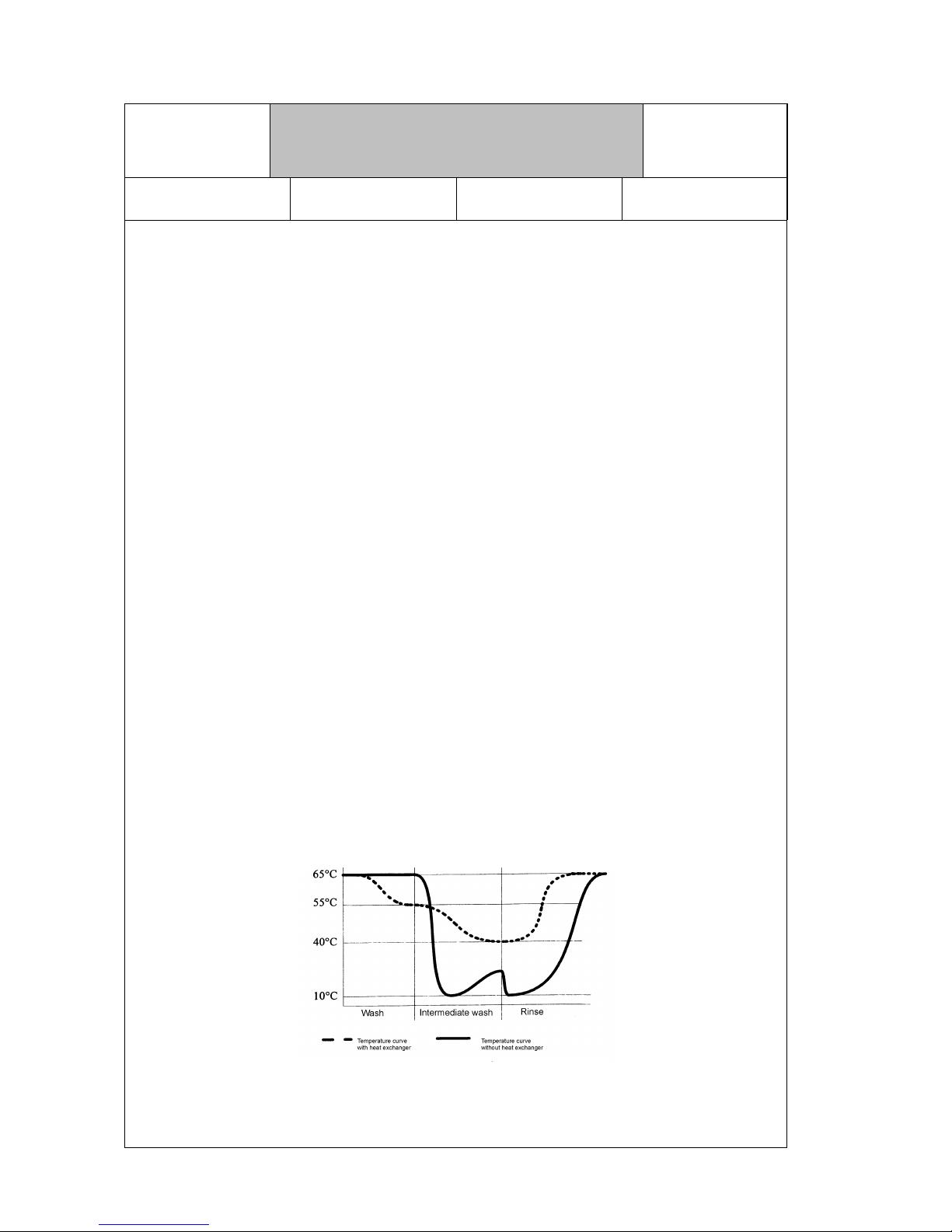
Warm water detection
The electronic control reacts to the connection conditions of the appliance and thus enables the
unlimited use of all dishwasher models, with or without heat exchanger, in case of warm water
connection.
If the control recognises that the appliance has been connected to warm water supply (if the
measured temperature of the inlet water during the rinse cycle exceeds 45 °C), the heat exchanger
will not be filled for the drying cycle. In order to ensure the temperature difference required for
condensation, the temperature will be increased to 70 °C during the rinse cycle and thus the
inherent heat of the dishes increased.
Smooth temperature transmissions due to heat exchanger
VKS-H
Technical Information
Dishwasher Series 630
H7-410-03-01
Responsible: Rutz Tel.: (0209) 401-733 Fax: (0209) 401-743 Date: 30.09.1998
For internal use only 4
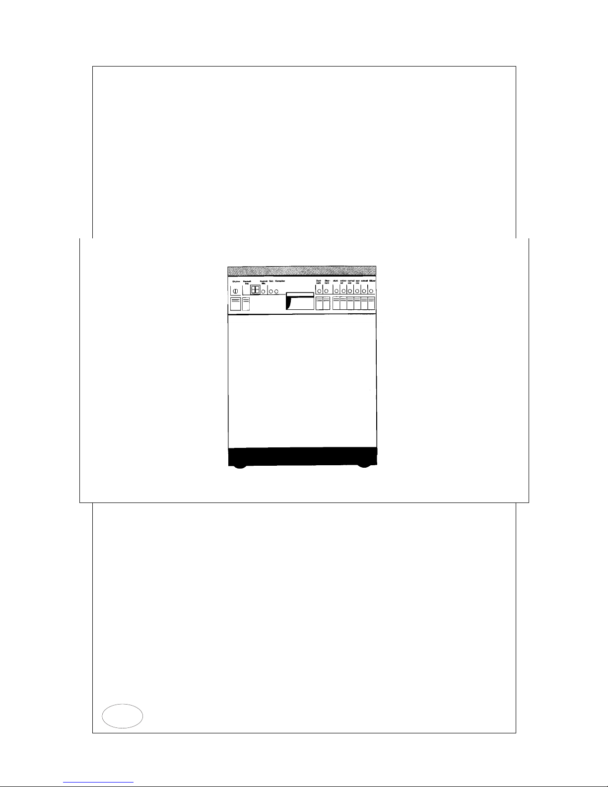
1.2 Operation and handling
The design of the new dishwasher series 630 is especially characterised by easy operation and
activation of the most frequently used operating elements. Daily handling of the new dishwasher s is
convenient and user-friendly thanks to easily comprehensible operating sequences requiring only
little force. The most important elements are:
• Selection of all functions via short-stroke buttons
• Remaining cycle time display
• Detergent metering chamber
• Filter system
• Door brake
Depending on the equipment, delayed program start can be selected on some dishwasher models.
This start time preselection is possible up to 24 hour s in Top electronic models and up to 9 hours in
Comfort electronic models.
Also after the program sequence has been started changing to another program or operating mode
is still possible by pressing the respective button twice. This safety feature prev ents unintentional
changing during a running program. In case of an intentional program change, the running program
is interrupted and the sequence continued at the respective point in the newly selected program. As
soon as "0" is displayed in the figure panel, the dishwasher has returned to the initial position and
can be newly started.
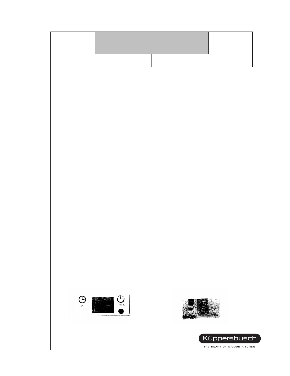
Remaining cyle time display
In case of dishwashers equipped with Top electronic the user is informed on the stage of the
running wash program: the remaining cycle time until program end (in minutes) is displayed on the
operating panel.
The remaining cycle time display is newly calculated and thus updated several times during the
program sequence. It mainly depends on the following factors: quantity and type of the dishes,
temperature of the inlet water as well as degree of dirtying of the dishes. For the initial calculation
after switching on of the dishwasher, always the values of the preceeding pogram are used. The
less the above-mentioned factors deviate, the less corrections are made as compared to the time
displayed first. The required correction amounts to approx. 10 minutes in the least favour able case.
The display is quartz-controlled and thus also reliable in case of deviations of the mains frequency.
In case of dishwashers equipped with Comfort electronic the program sequence display is
performed by means of an LED "bar", which indicates the individual phases of the wash program
(basically comparable to the program "indicator" of the previous series).
F
Remaining cyle time display Sequence display
VKS-H
Technical Information
Dishwasher Series 630
H7-410-03-01
Responsible: Rutz Tel.: (0209) 401-733 Fax: (0209) 401-743 Date: 30.09.1998
5 For internal use only
Filter system
The filter system consists of 3 parts: coarse, fine and micro-filter. The coarse and micro filter may be
taken out by means of of a joint handle, the fine filter is separately located in the container bottom.
Due to the surface increased by 30 % and the permanent cleaning during the wash cycle by means
of a special nozzle at the underside of the bottom spray arm, the fine filter has to be checked for
clogging only twice per year.
Furthermore, the newly designed coarse filter serves for improved self-cleaning. It is open towards
the drain pump and allows all foreign matters to pass thr ough that may be bor ne by the dr ain pump.
In this way it is ensured that the filter s ystem will not be clogged by left-overs of food. All larger
matters of dirt that cannot be transported by the drain pump are collected in the collection groove of
the coarse filter from where they can be easily removed.
Filter system
Door brake
In contrast to the dishwasher models of the previous series the door does not automatically fall
down but remains in any desired position. This feature allows to open the door only half the
way, e. g., when charging the upper basket or during filling of the detergent chamber and thus
enables the user to close the door without bending down.
VKS-H
Technical Information
Dishwasher Series 630
H7-410-03-01
Responsible: Rutz Tel.: (0209) 401-733 Fax: (0209) 401-743 Date: 30.09.1998
For internal use only 6

1.3 Improved installation and connection
Erection, installation and connection have been considerably facilitated for the dishwasher models
of the new series thus enabling the kitchen fitter and plumber to intergrate our dishwashers more
quickly and more easily into the kitchen. The following items are to be especially noted:
• Aqua Stop
• Installation reserve in the appliance height
• Adjustments from the front
• Infinite panel adaptation
Aqua Stop
Above all, the installation and handling of the Aqua Stop system has been facilitated by a number of
improvements. Inlet and outlet hose are separated from each other in any dishwasher model in
order to be more flexible in case of unfavourably located water connections. The Aqua Stop housing
is smaller althouhg its operativeness remains unchanged. In this way, installation thorugh the
bottom cupboards of the kitchen is facilitated .
A significant a dvantage of t he new Aqua S top is that it can be installe d in any desired pos ition,
also at an angle, hori zonally or, in extr eme cases, overhe ad. Besides that, the minimum height
for the inlet connection (0.3 m above the installation surface of the appliance) needs no longer
to be observed.
To this end, the valve system has been changed: the pneumatic valve in the Aqua Stop housing
has been replace d by a second magne tic valve. As the valves are dir ectly located on the water
tap and are c losed in d e-energiz ed condit ion, safety can be continually ensured i ndependent of
the mains. The Aqua Stop guarantee is of course also fully granted for the new dishwasher
models.
Furthermore, the discharge hose can be installed at any location on the dishwashers of the new
series, as the verti cal instal lati on tha t has been req uir ed so far is no longe r nece ssar y due to the
"hose bend". This has been rea lised by a vertic al installation and ventilation of the water outlet
already in the dishwasher itself. With respect to the appliance, it is thus ensured that no
malfunctions like emptying of the appliance or penetration of dirty water from clogged drain
pipes may occur.
In order to extend the inlet hose, acc. part no. 485 may be installed at the new dishwasher
models. The di scha rge h ose ca n be ex tended by means of a commerc ial plastic hose to
max. 4 m, if required .
VKS-H
Technical Information
Dishwasher Series 630
H7-410-03-01
Responsible: Rutz Tel.: (0209) 401-733 Fax: (0209) 401-743 Date: 30.09.1998
7 For internal use only
Installation reserve in the appliance height
To faciliate the installation the body height of all appliances of the new series, including stand-alone
and built-under models suitable for decoration, is reduced by 10 mm (see p. 18 - Installation
dimensions). This ensures, especially in case of replacement, easy installation also with narrow
niche conditions, e. g. unlevel ground, carpet, subsequently layed flooring materials. Furthermore,
the appliances can thus also be installed in kitchens with special niche dimensions (heights between
810 and 820 mm).
Adjustments from the front
The height of the rear foot as well as the prestr ess of the door springs (weight compensation of
furniture fronts) can be adjusted from the front at all intergrated and fully integrated dishwasher
models of the new series.
Adjustment of door springs and rear foot
Thus the appliance needs not to be repeatedly inserted and pulled out for alignment and
adjustment. All adjustments may be performed by means of the s crews loc ated in the base after the
appliance has been inserted into the niche.
At the same time, the design of the door springs has been changed in s uch a way that they are
suitable for furniture fronts of max. 10.5 kg in case of built-in appliances.
VKS-H
Technical Information
Dishwasher Series 630
H7-410-03-01
Responsible: Rutz Tel.: (0209) 401-733 Fax: (0209) 401-743 Date: 30.09.1998
For internal use only 8

Infinite panel adaptation
In order to adapt the panel height to the drawer dimensions of the kitchen furniture a set of cover
strips with infinitely adjustable height is used for integrated appliances. This set consists of 4 strips
with a height of 8 mm each, which may be each telescoped into each other up to 3 mm. By means
of the complete set, a height difference of up to 32 mm may thus be compensated. The strips may
be assembled and disassembled without tool.
An exception are all appliances equipped with stainless steel operation panel. For these models 3
stainless strips are supplied, which may be used alternatively.
Spare part no. 42 67 44 up to 17.5 mm
42 66 11 up to 27.5 mm
42 66 10 up to 37.5 mm
Two further stainless steel strips may be supplied as accessory:
Spare part no. 42 67 45 up to 47.5 mm
42 67 46 up to 57.5 mm
VKS-H
Technical Information
Dishwasher Series 630
H7-410-03-01
Responsible: Rutz Tel.: (0209) 401-733 Fax: (0209) 401-743 Date: 30.09.1998
9 For internal use only
Appliance heights of 82 and 87 cm
In the kitchens, increased worktop heights tend to gain more and more acceptance for ergonomical
reasons. Today 55% of the new kitchens in Germany are already equipped with worktop heights of
91 cm and more. In Scandinavia, Great Britain and the Netherlands the proporotions of these height
dimensions are significantly higher.
Especially for those "high" kitchens, a further innovation is provided: dishwashers with a height
increased by 5 cm which ensure optimal utilisation of the available space. In contrast to
dishwashers with "normal" height these "extra-large" dishwashers offer an increased internal height
of 5 cm. These dishwashers are suitable for all kitchens with a niche height of at least 86 cm and a
body size (niche height minus base height) between 70 and 72 cm. In comparison with that: The
"normal" appliances are suitable for body sizes of 65 to 72 cm, with the minimum niche dimension
amounting to 81 cm.
In order to select the ideal appliance for a certain kitchen it is thus important to know the base
height in addition to the existing niche height, as the application of the dishwasher is determined by
the difference between them.
Niche height in mm
810 820 830 840 850 860 870 880 890 900 910 920
90
②❼
100
②② ❼❼
110
②②② ❼❼❼
120
②②②② ❼❼❼❼
130
②②②②②❼❼❼❼❼
140
②②②②②②❼❼❼❼❼❼
150
②②②②②②❼②❼❼❼❼❼❼
160
②②②②②②❼②❼❼❼❼❼❼
170
②②②②②②❼❼❼❼❼❼
180
②②②②②❼❼❼❼❼
190
②②②② ❼❼❼❼
200
②②② ❼❼❼
210
②② ❼❼
220
②❼
② dishwasher 82 cm ❼ dishwasher 87 cm
Possible installations in case of a niche height of 87 cm
VKS-H
Technical Information
Dishwasher Series 630
H7-410-03-01
Responsible: Rutz Tel.: (0209) 401-733 Fax: (0209) 401-743 Date: 30.09.1998
For internal use only 10

1.4 Further technical innovations
In the following chapters further innovations of the dishwasher series 630 are summarized and
explained. These modifications have also resulted in improved operation, performance, quality and
optical aspects of the appliance.
1.4.1 Wash system
The wash system of the dishwashers has been further developed with the aim to achieve an optimal
cleaning result with the lowest possible consumption of water and energy. The following appliance
components contribute to reach this aim:
Heat exchanger
The heat exchanger, which is still an exc lusive feature of Küppersbusch appliances, is also offered
in the new series. The heat exchanger offers a multitude of operating advantages like economical,
hygienic drying, gentle temperature guidance, no penetration of steam when the door is opened
after the program end. The heat exchanger is, above all, installed in top class dishwashers, partially
also in middle class appliances . Due to the warm water detection of the electronic sys tem a good
drying performance is also achieved in case of warm water connection.
Spray arms
An obvious characteristic feature of the new series is represented by the curved "wave-type spray
arms" that are exclusively installed in Küppersbusch dishwashers. The advantage of this design is
an improved spraying of the entire dishwasher interior, i. e. no more "dead angles" that are not
reached by the spray arms. All pieces of the dishes are thus reached by the spraying jets and
cleaned accordingly.
Both spray arms of the new dishwasher series - also the lower arm - are made of plastic. This
enables a more precise design and more exact alignment of the spraying nozzles as well as a lower
weight which results in a faster rotation of the spray arms and thus an improved distribution of the
water.
Water guidance
The entire water guidance from the pump casing to the spray arms and the top spray has been
newly designed and is now located in the inside of the rinse container. This leads to a reduction of
the inactive water quantity and thus to an improved washing result.
The water guidance to the upper spray arm is also new. The spray arm is connected to the supply
by means of a movable coupling and directly mounted at the upper basket. For this reason, no more
space-consuming funnel is required for any appliance. Thanks to this new coupling, height
adjustment and even removal of the upper basket with spray arm is now also possible without
funnel. In the latter case, the entire internal space of the appliance (51 or 56 cm, respectively) is
then available, for example for washing baking trays.
VKS-H
Technical Information
Dishwasher Series 630
H7-410-03-01
Responsible: Rutz Tel.: (0209) 401-733 Fax: (0209) 401-743 Date: 30.09.1998
11 For internal use only

Flow heater
All appliances of whatever class belonging to the dishwasher series 630 are equipped with an
integrated flow heater to heat the water. Thus the new generation does not include appliances with
visible tubular heating any more. The complete range of advantages provided by the flow heater
(increased internal height, no damaging of plastic dishes, no carbonisation of remaining food) is only
provided in Küppersbusch appliances.
1.4.2 Dish baskets
In the new series two different types of dish baskets are used: standard baskets and universal
baskets.
The standard baskets are identical with those of the series 624 (dishwashers with heat exchanger).
The upper basket is suitable for up to 4 rows of glasses or cups and one row of small plates. The
lower basket is equipped with two rows of plates designed as fixed or removable inserts, depending
on the model (see "Appliance range and equipment"). In case of the appliances with removable
inserts the special accessory "Special glass basket" may be used.
The universal baskets are already known from the series 624 ( upper basket dishwashers). They
offer variable charging of the upper and lower basket and allow location of 6 standard dishes
including all parts like pots, bowls and pans only in the upper basket. The universal baskets are
included in the standard equipment of all upper basket dishwashers.
Furthermore, the new dishwasher models allow adjustment of the basket height for the upper
basket appliances which means a further improv ement of the flexible charging. The heights are factory-set to 26 cm at the top and 25 cm at the bottom. If required, this setting can be changed to 21
cm at the top and 30 cm at the bottom. Thus, these appliances are also suitable for pieces of dishes
up to a height of 30 cm (if arranged at an angle even up to 33 cm). Adjustment of the upper basket
has been facilitated: the basket is simply lifted of the guide rails and inserted in the second height
position.
The standard baskets are generally supplied with 21 cm top height and 30 cm bottom height. No
adjustment is possible here. The heights of the "high" appliance types amount to 26 cm at the top
and 30 cm at the bottom, no adjustment possible.
VKS-H
Technical Information
Dishwasher Series 630
H7-410-03-01
Responsible: Rutz Tel.: (0209) 401-733 Fax: (0209) 401-743 Date: 30.09.1998
For internal use only 12
The heights of all appliance types are summarised in the following table:
Height 82 cm Height 87 cm
Standard
baskets
Universal
baskets
Standard
baskets
Universal
baskets
Height upper basket
- arranged at an angle
21 26
29
26
29
26
29
Height lower ba sket
- arranged at an angle
30
33
25
28
30
33
30
33
Adjustable to:
Height upper basket
- arranged at an angle
21
Height lower ba sket
- arranged at an angle
30
33
1.4.3 Softening system
The filling capacity of the salt container of the new dishwasher models amounts to 1.5 kg and is
sufficient for approx. 70 standard wash cycles with a water hardness of 5. After lighting up of the
salt refill indicator approx. 5 wash cycles can still be peformed before the salt container is
completely empty. The operation of the softening system depends on the respective control.
1.4.4 Noise
The appliances of the new series are equipped with 2 noise insulating stages: 48 dB and 45 dB.
These values always apply to the sound power dB (re 1 pW) for a built-under appliance.
Apart from some exceptions, all electronic appliances will be equipped with 48 dB. This v alue is so
low that it is not audible compared to the normal noise level in the r oom. This equipment enables us
to offer a large variety of low-noise dishwashers.
1.4.5 Turbo drying
The electronic appliances of the new dishwasher series enable the operator, if desired, to select a
more intensive drying function which, of course, results in an increased energy consumption.
In order to program this turbo drying, switch the dishwasher on while keeping the button
"Heavy-load 65°" depressed. The preset value "0" (= turbo drying off) will then be indicated in the
7-segment display. The function is actually activated by pressing the button "Heavy-load 65°" once
again. The value "1" (= turbo drying on) will be displayed. After switching off the appliance, the new
value is stored.
VKS-H
Technical Information
Dishwasher Series 630
H7-410-03-01
Responsible: Rutz Tel.: (0209) 401-733 Fax: (0209) 401-743 Date: 30.09.1998
13 For internal use only

1.4.6 Connection value
All dishwashers of the new series have a heating capacity of 2150 W and thus a connection value of
2300 W; therefore a fuse protection of at least 10 A is required. Due to this feature, all dishwashers
may also be used at locations where no 16 A protection is available in the future. Special
low-protection variants, as are partially existing today, are no longer required.
1.4.7 Rinse aid metering chamber
The location, filling, metering adjustment and refill indicator of the rinse aid chamber have been
taken over from the acutal dishwasher models. Only the lid has been modified; it is now fixed to the
cabinet. Thus loss or misplacement of the lid is avoided.
The filling capacity of the rinse aid chamber amounts to 110 ml; in position 3, 3 ml are added per
wash program. Thus approx. 25 rinse cycles may be performed until the refill indicator lights up.
1.4.8 Ventilation
The inner container of the new dishwashers has no openings in the top, lateral and rear wall. The
only outlet for the produced steam is located in the inner door, integrated in the refill assembly for
detergent and rinse aid. The steam condenses in a separate channel in the inner door and is
recirculated below the door to the container bottom. In this way, the penetration of the steam
towards the top which results in the risk of a damaging of the worktops in this area is avoided.
1.4.9 Operating safety
All appliances (except fully integrated appliances) are equipped with a safety device in case of
opening during the program sequence, i. e. a direct circuit-breaker which is operated when the door
opener is activated. When the appliance is opened, it will be immediately switched off via the mains
switch. After closing the door and switching on again, the program will be continued at the same
point. Besides that, all upper basket dishwashers are equipped with a child-proof loc k located in the
door handle to protect the appliance from being switched on unintentionally. When the child-proof
lock has been activated, the appliance can only be opened by pressing an additional pin in the
handle recess. If not required, the child-proof lock can be deactivated by means of a ballpen or
equivalent.
1.4.10 Salt refilling
The refilling of regeneration salt in the container bottom has been facilitated by shifting the filling
opening towards the front. Furthermore, a salt funnel is supplied with all appliances.
VKS-H
Technical Information
Dishwasher Series 630
H7-410-03-01
Responsible: Rutz Tel.: (0209) 401-733 Fax: (0209) 401-743 Date: 30.09.1998
For internal use only 14

1.4.11 Feet and skids
The feet are made of plastic with extended foot plates in order to avoid damaging of flooring
materials. Stand-alone appliances and appliance suitable for decoration are equipped with four,
built-in appliances with three feet (two at the front, one at the rear in the middle) that ensure stable
standing on any ground.
The skids for easier sliding of the appliance into the furniture niche are integrated in the bottom tub.
In this way the installation of the appliances is even more faciliated.
1.4.12 Mounting at the kitchen furniture
For mounting the built-under appliances (suitable for decoration, integrated and fully integrated) at
the kitchen furniture two metal brackets to be inserted into the force sensors at the top of the
appliance are supplied. Each of the metal brackets has two fastening locations. In case mounting at
the worktop is not possible (e. g. stone or granite worktops), these brackets may als o be used for
lateral mounting at the furniture body.
In order to protect kitchen worktops against being damaged by emerging steam, for example when
opening the door during the program sequence, all built-under appliances are supplied with a s team
protection foil to be mounted at the underside of the worktop.
VKS-H
Technical Information
Dishwasher Series 630
H7-410-03-01
Responsible: Rutz Tel.: (0209) 401-733 Fax: (0209) 401-743 Date: 30.09.1998
15 For internal use only
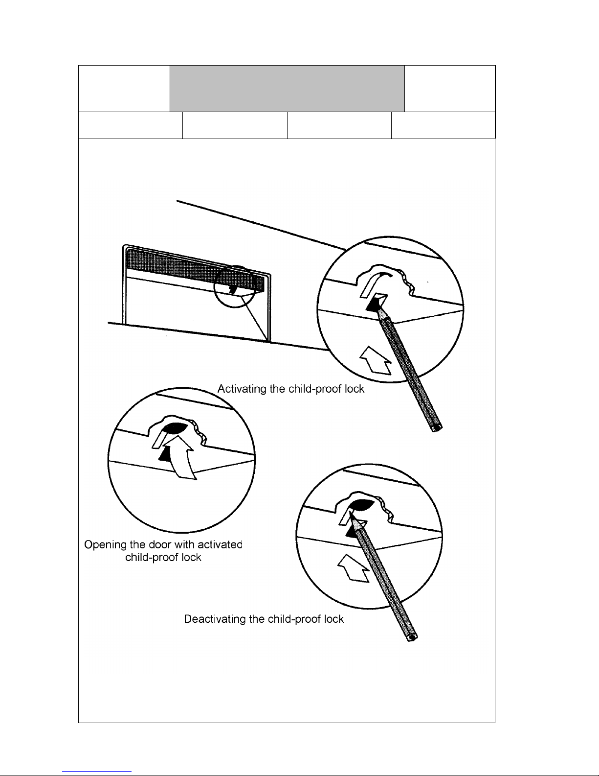
1.4.13 Child-proof lock
VKS-H
Technical Information
Dishwasher Series 630
H7-410-03-01
Responsible: Rutz Tel.: (0209) 401-733 Fax: (0209) 401-743 Date: 30.09.1998
For internal use only 16
1.5 Technical Data
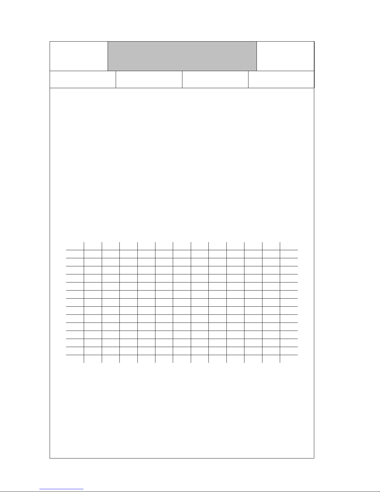
1.5.1 Consumption values
Electronic with heat exchanger
Programs 2 x 6
Prog.
5
Prog.
2 x 4
Prog.
Water
(ltr.)
Current
(kWh)
Time
(min.)
Pots 70 °C
upper basket
x 18 / 23*
14 / 18*
1,7 / 1,8*
1,2 / 1,3*
99
90
Heavy-load 65 °C
upper basket
x
x
xxx18 / 23*
14 / 18*
1,4
1,1
95
85
Normal 55 °C
upper basket
x
x
xxx14 / 18*
11 / 14*
1,2
0,9
90
82
Eco 55 °C
upper basket
x
x
xxx16
13
1,2
0,9
90
81
Glasses 40 °C
upper basket
x
x
14
11
0,9
0,7
58
52
Quick
upper basket
x
x
xxx12
10
1,0
0,8
30
25
* thanks to Aqua Sensor low value in case of standard dirtying
Electronic without heat exchanger
Program 5
Prog.
4
Prog.
Water
(ltr.)
Current
(kWh)
Time
(min.)
Heavy-load 65 °C x x 23 1,6 95
Normal 55 °C x x 18 1,4 90
Eco 55 °C x x 16 1,4 90
Glasses 40 °C x 14 1,1 58
Quick x x 12 1,0 30
Mechanic
Program 5
Prog.
4
Prog.
Water
(ltr.)
Current
(kWh)
Time
(min.)
Heavy-load 65 °C x x 25 1,6 95
Normal 65 °C x 20 1,5 95
Normal 55 °C x 20 1,4 92
Eco 55°C x 16 1,4 88
Energy saving x 17 1,3 75
Quick x 12 1,0 45
VKS-H
Technical Information
Dishwasher Series 630
H7-410-03-01
Responsible: Rutz Tel.: (0209) 401-733 Fax: (0209) 401-743 Date: 30.09.1998
17 For internal use only
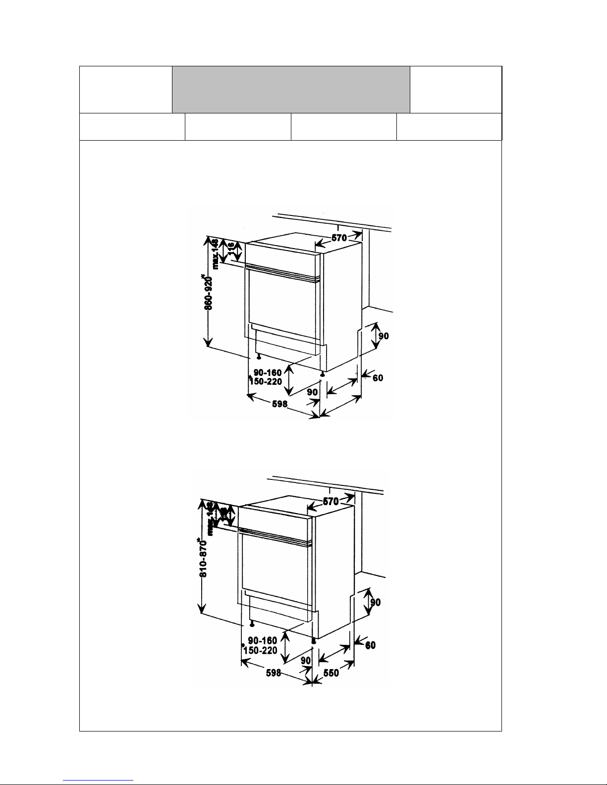
1.5.2 Installation dimensions
VKS-H
Technical Information
Dishwasher Series 630
H7-410-03-01
Responsible: Rutz Tel.: (0209) 401-733 Fax: (0209) 401-743 Date: 30.09.1998
For internal use only 18
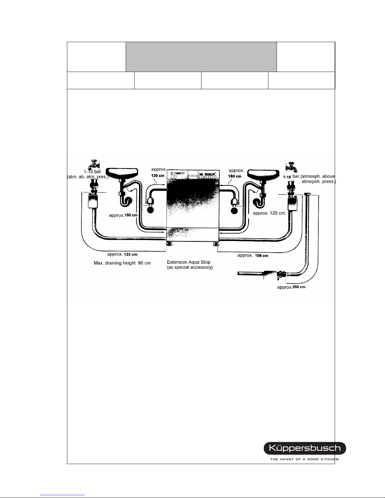
1.5.3 Connection dimensions
VKS-H
Technical Information
Dishwasher Series 630
H7-410-03-01
Responsible: Rutz Tel.: (0209) 401-733 Fax: (0209) 401-743 Date: 30.09.1998
19 For internal use only

2. GENERAL TECHNICAL DESCRIPTION
2.1 Structure
2.2 Housing parts
The lower edges of the side walls are inserted into the tub. Attachment is via 2 screws each at the
front and rear of the appliance. The outer door, which is screwed to the inner door, is attached
belo w th e a c c ess pa nel with brac ke ts in t he su ppor t. For sta nd-al one m odel s, t he ta ble t op is a tt ached
at the four supports. Built-under models have a divid ed, heig ht-ad justa ble oute r doo r for diff erent base s.
2.3 Rinse container
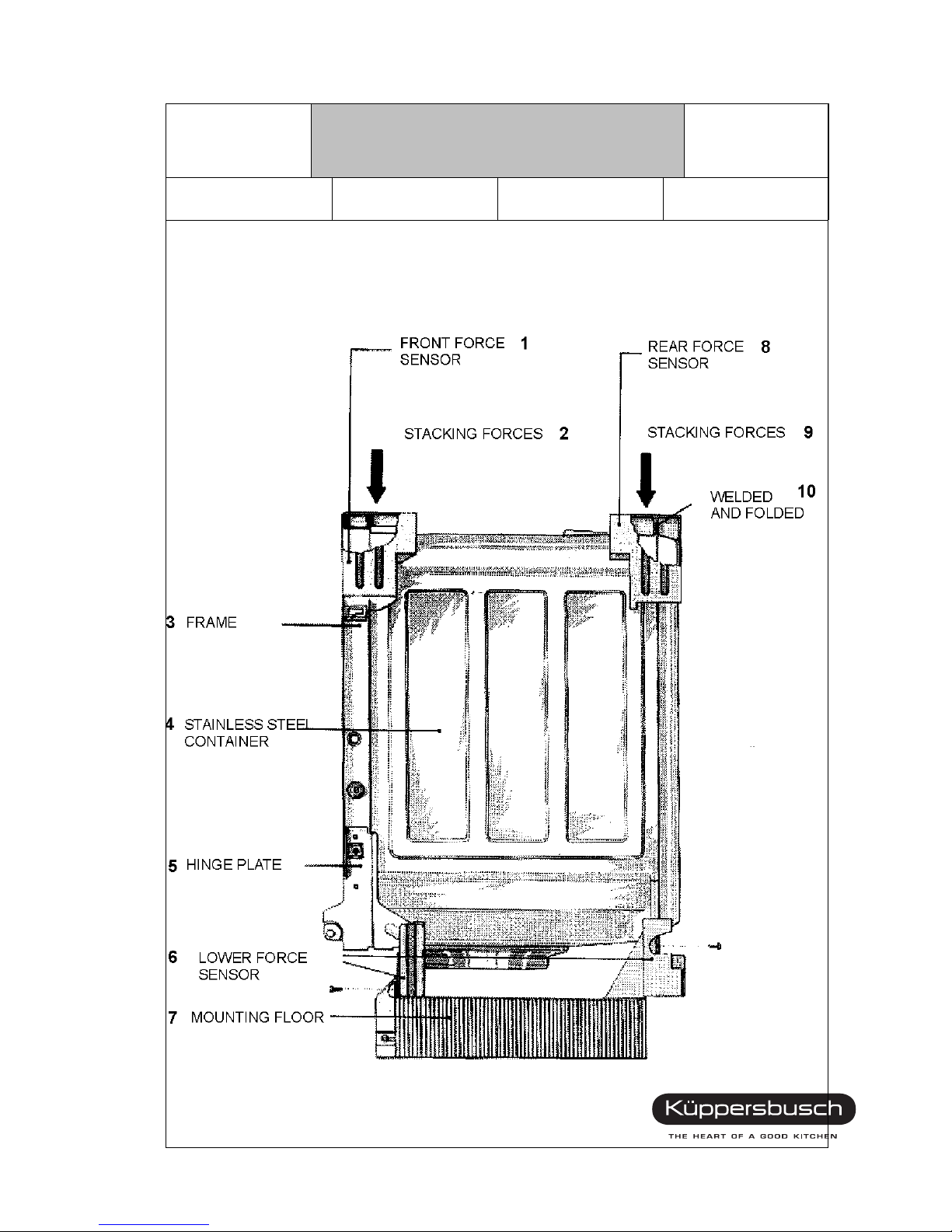
The bitumen coated stainless steel inner container has a U- channel around the door area which is
welded to the container. The welded rear wall is also double stacked on all four sides with the
container. These doubled and lock-seamed connections provide rigid and safe container edges. The
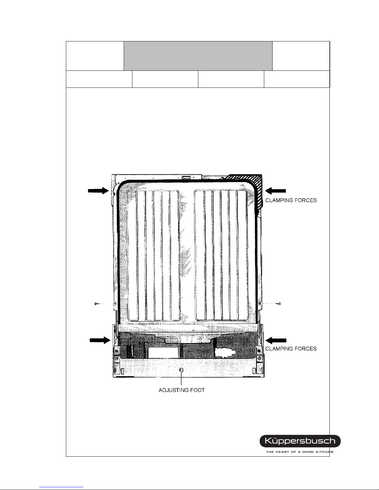
specially formed supports at the upper container corners, to which the housing parts are also
attached, absorb the load and clamping forces. The softening system is screwed down to the
container bottom. The heat exchanger with integrated water i nlet is att ache d at the le ft co ntai ner
wall with tw o rails . The connection between heat exchanger, softening system and level sensor
system is made via hoseless plug connections.
2.4 Inner door
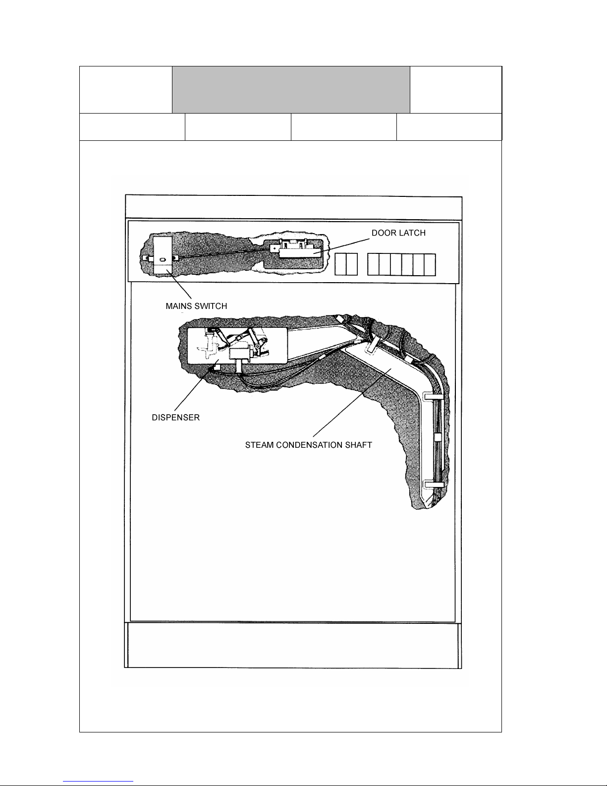
The dispenser assembly is locked into the stainless st eel inner door, which is als o bitumen c oa te d .
The surge water seal is screwed to the inner door using the seal rail and snapped onto the
container edge. The edges of the inner door are doubled and lock-seamed for no sharp
edges. The container is vented through the housing of the dispenser assembly. A steam
condensation tube fitted into the housing between the inner and outer doors passes condensates
during the heating cycles or expansion peaks back into the container. The control, mains switch,
displays and door latch are attached to the support which is screwed to the inner door.
The access panel is fixed on the support.
VKS-H
Technical Information
Dishwasher Series 630
H7-410-03-01
Responsible: Rutz Tel.: (0209) 401-733 Fax: (0209) 401-743 Date: 30.09.1998
For internal use only 20
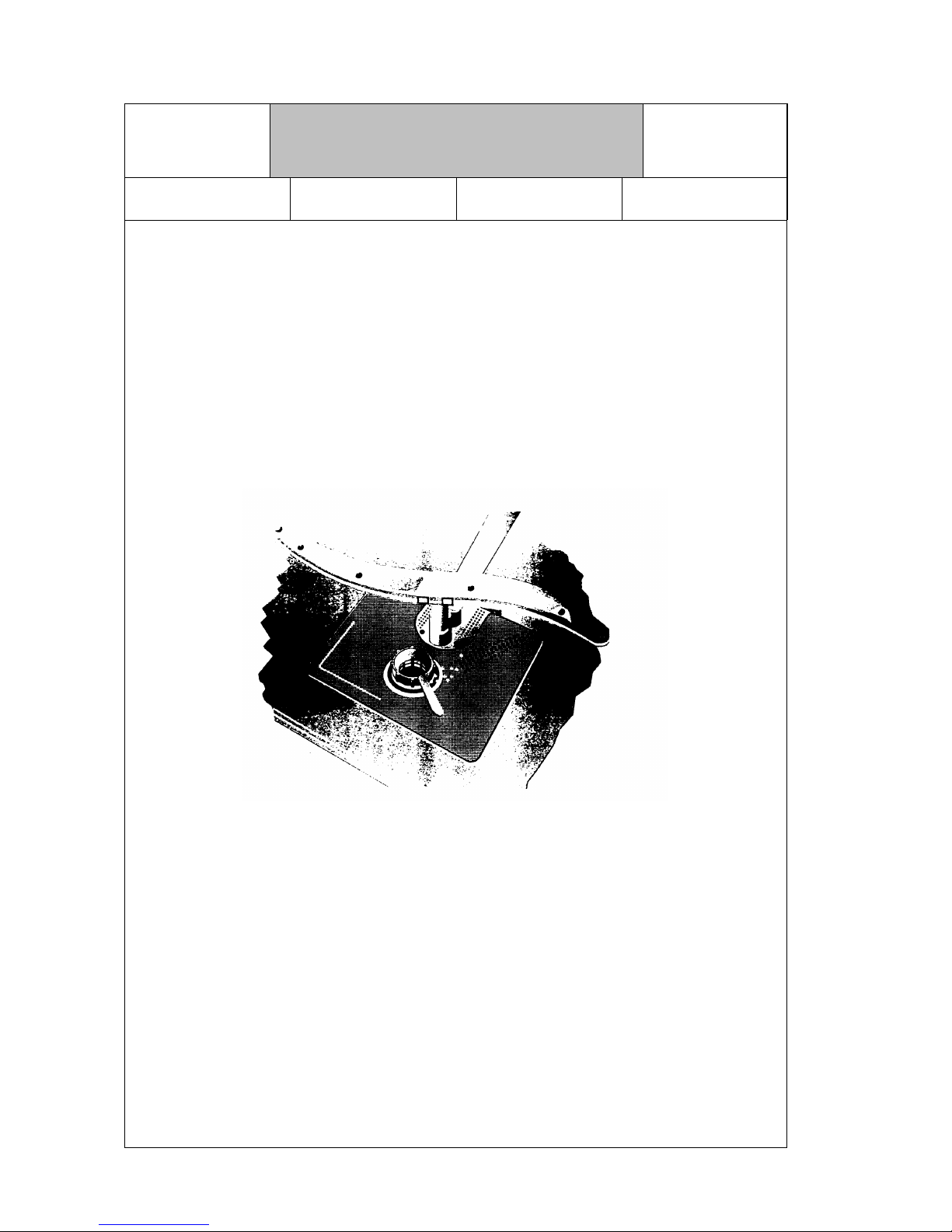
RINSE CONTAINER
VKS-H
Technical Information
Dishwasher Series 630
H7-410-03-01
Responsible: Rutz Tel.: (0209) 401-733 Fax: (0209) 401-743 Date: 30.09.1998
21 For internal use only
VKS-H
Technical Information
Dishwasher Series 630
H7-410-03-01
Responsible: Rutz Tel.: (0209) 401-733 Fax: (0209) 401-743 Date: 30.09.1998
For internal use only 22
2.5 Tub
The plastic tub contains the pump system with flow heater, pump casing, drain and recirculation
pump, the level and safety system, as well as the float for shutting off when water is in the tub. The
drain and Aqua Stop hoses are brought in separately at the rear left of the tub. The electrical
connection with main filter is at the right rear.
The rear wall of the tub is formed such that it serves both as a support and attachment member for
the rinse container. The front support and attachment is made using the extended hinge plates of
the door hinges in the tub, which are screwed to the U-frame of the container.
TUB
VKS-H
Technical Information
Dishwasher Series 630
H7-410-03-01
Responsible: Rutz Tel.: (0209) 401-733 Fax: (0209) 401-743 Date: 30.09.1998
23 For internal use only
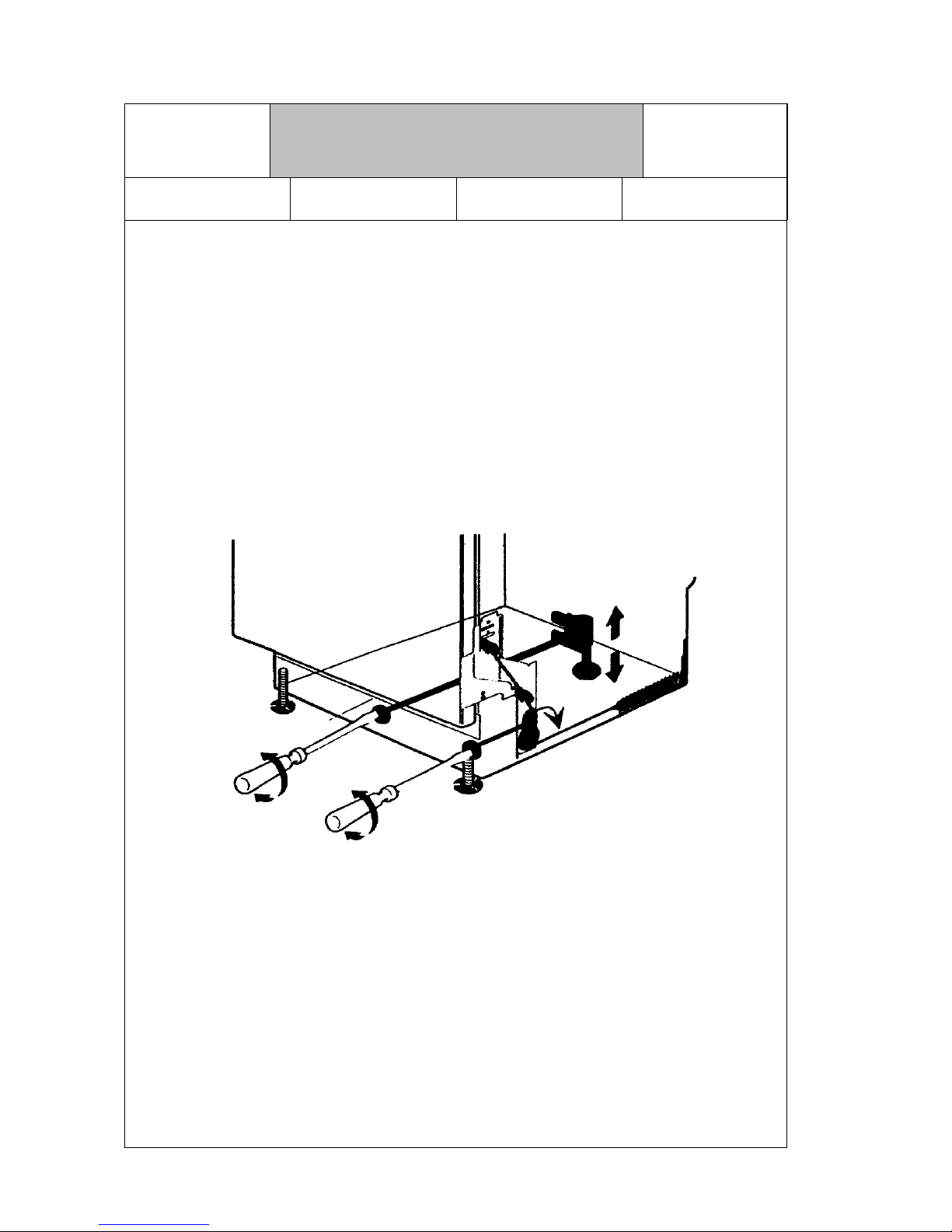
2.6 Door spring adjuster
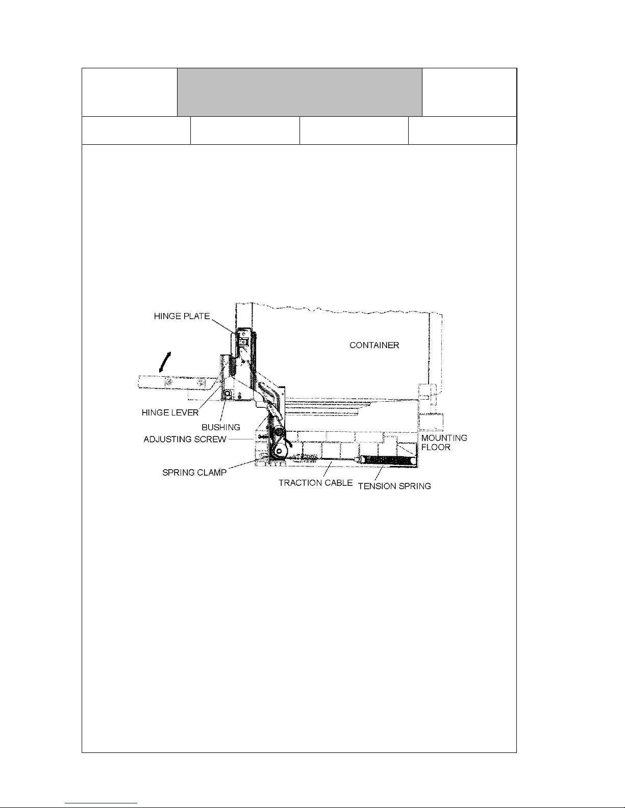
The adjusting assembly consists of the tension spring, the cable, spring adjuster and adjusting
screw. The te nsi on s pr ing s ar e at ta c he d b el ow th e t ub at the rear wall u s in g b r ack e ts . The tension cable
is fed to the hinge plate over the spring adjuster, angled and hung into the hinge lever of the door.
DOOR HINGE WITH TENSION SPRING
2.7 Height adjustment
The integrable and built-under models have two adjusting feet in front and a rear foot which is
adjustable for height from the front. The stand-alone models have four identical adjusting feet, the
front ones in the base.
VKS-H
Technical Information
Dishwasher Series 630
H7-410-03-01
Responsible: Rutz Tel.: (0209) 401-733 Fax: (0209) 401-743 Date: 30.09.1998
For internal use only 24
2.8 Spray system
The rotary spray system cons ists of three spray levels , the lower and upper spray arm and a top
spray .
The water supply to the upper spray arm and the top spray is brought through the inlet pipe
atta ched to t he inside of the co ntainer r ear wall . This pip e is conne cted by a direct connection
with the flow heater under the pump casing at one of its two outlets.
The upp e r sp r a y a rm i s di r e ct l y f as t e n ed w ith its in l et p ip e to t he u pp e r ba s k e t . The connection to
the inlet pipe is thro ugh a var i ab le cou pl in g. In mo dels w it h h ei gh t adj ust ab le uppe r basket, the water entry
is adapted to the spray arm using this variable coupling.
The connection to the inlet pipe is through a variable coupling. In models with height adjustable upper
basket, the water en tr y is adap te d to t he sp r ay ar m u sin g this var i ab le co up li ng .
The lower spray arm with its bearing is connected directly through the pump casing at the
second outlet of the flo w heat er.
The valve for the upper basket wash cycle is located in this outlet.
2.9 Wash and pump system
The switching mechanism with the permanent magnet and actuator is attached beneath the flow
heater. The recirculation and drain pump as well as the flow heater are attached to the pump casing
using plug connections. The flow heater is additionally screwed to the pump casing for pressure
resistance.
The pump casing is covered by the area fine filter. With the combined coarse and micro-filter, the
fine filter is attached to the floor of the pump casing using a bayonette mount. The washing liquid
accumulating in the pump casing is drawn by the recirculation pump and pressed into the flow
heater. At the appropriate pressure a flange membrane actuates the pressure switch for the heater
A series connected temperature controller with a turn-off temperature of 85 °C prevents
overheating.
This temperature switch is combined with an NTC resistor (Negative Temperature Coefficient)
(otherwise 55/88 °C) into a single component, and is only used in models with electronic control.
The NTC surface has direct contact with the wash liquid. At the outlet of the flow heater is the Aqua
sensor with its sensor in the flow current of the wash liquid for detecting turbidity of the water. With
the drain pump directly attached to the pump casing, the impeller and the check valve are
accessible after removing the cover in the rinse container.
VKS-H
Technical Information
Dishwasher Series 630
H7-410-03-01
Responsible: Rutz Tel.: (0209) 401-733 Fax: (0209) 401-743 Date: 30.09.1998
25 For internal use only
 Loading...