

Kuppersbusch IG 4408.0, IGV 4408.0, IG 4406.0, IG 4408.1 Service Manual
Service Manual - Series 450/451
IG 448... IGV 449...
IG 458... IGV 459...
IG 459... IG 4408.0
IG 4406.0 IGV 4408.0
IG 4408.1

Service Manual: H7-71-04
Responsible: Dieter Rutz KÜPPERSBUSCH HAUSGERÄTE AG
Email: dieter.rutz@kueppersbusch.de
Phone: (0209) 401-733 Kundendienst
Fax: (0209) 401-743 Postfach 100 132
Date: 21.11.2008 45801 Gelsenkirchen

Service Manual 3
Contents
1. Safety...............................................................................................................................5
2. General technical specification - 45cm appliances ................... ... .... ... ... ... .... ... ... ... ... . 6
3. Assembly......................................................................................................................... 7
3.1 Installing................................................................................................................7
3.2 Electric connection ................................................................................................7
3.3 Water connection ..................................................................................................7
4. Functional description of the single groups................................................................ 8
4.1 IGV 4... operation ..................................................................................................8
4.2 IG 4... operation...................................................................................................10
4.3 Initial operation / electronics exchange ............................................................... 15
4.4 IG 458.1E operation ............................................................................................17
4.5 Construction components....................................................................................18
4.6 IG 4406.0E operation ..........................................................................................21
4.7 Construction components....................................................................................22
4.8 IGV 4408.0 operation ..........................................................................................25
4.9 Construction components....................................................................................26
5. Explanation of the rinsing instructions......................................................................29
5.1 Coding instructions for an electronics system with G controls IG 4... .................29
5.2 Customer service test program: G controls (with heat exchanger) .....................30
5.3 H controls operation ............................................................................................37
5.4 Coding instructions for an electronics system with H controls ............................41
5.5 Customer service test program: H controls (without heat exchanger) ................ 42
5.6 Trouble shooting..................................................................................................47
5.7 W controls operation ........................................................................................... 48
5.8 Initial operation / electronics exchange ............................................................... 51
5.9 Coding instructions for an electronics system with W controls
(IGV 449.2).................................................................................. ... ... ... .... ... ... ... .. 53
5.10 Customer service test program: W controls (IGV 449.2)..................................... 54
6. Construction components...........................................................................................58
6.1 Actuator............................................................................................................... 58
6.2 Aqua sensor........................................................................................................59
6.3 Flow sensor... ... ........................................................... ... .....................................59
6.4 Axial flow sensor ................................................................................................. 60
6.5 Info light (optional) ..............................................................................................60
6.6 Aqua Stop System...............................................................................................61
6.7 Temperature safety system (NTC)......................................................................62
6.8 Salt and clear rinse agent display .......................................................................62
6.9 Hinge................................................................................................................... 63
6.10 Dispensing device ...............................................................................................64
6.11 Visual clear rinse fill-up sensor............................................................................65
6.12 Water softener.....................................................................................................65
6.13 Sieve system........................................ ... ... .... ... ... ... .... ... ... ..................................66
6.14 Rinse water pump ............................................................................................... 67
6.15 Rinsing and pump system.............................................. ... ... ... .... ... ... ... .... ... ... ... .. 68
6.16 Door seal.............................................................................................................68
6.17 Door spring..........................................................................................................69
6.18 Circulation pump (SICASYM)..............................................................................70
6.19 Combined detergents (3 in 1), according to the model ......................................72
6.20 Water points ........................................................................................................73
For internal use only

4 Service Manual
6.21 Continuous flow heater........................................................................................74
6.22 Equipotential system with a safety function.........................................................75
6.23 Rotary spray system............................................................................................76
7. Fill system ................................................................................ ... .... ... ... ........................77
7.1 Intake of water with heat exchanger....................................................................77
7.2 Regeneration with heat exchanger.............................. ... ... .... ... ... ... ... .... ... ... ... .... .78
8. Remedying faults for all of the series 45 cm..............................................................81
8.1 Controller / module ..............................................................................................81
8.2 Discharge ............................................................................................................82
8.3 Smell....................................................................................................................83
8.4 Noises..................................................................................................................84
8.5 Food or sandy deposits .......................................................................................85
8.6 Lime deposits ....................................... ... .... ... .....................................................87
8.7 Starch deposits....................................................................................................87
8.8 Water-soluble or regeneration salt residue on the dishes ...................................88
8.9 Discolouration / residual colour ...........................................................................89
8.10 Residual detergent ............................ ... ... .... ... .....................................................90
8.11 Damage to rinsed dishes.....................................................................................91
8.12 Drying results.......................................................................................................92
8.13 Circulating pump..................................................................................................92
9. Technical data IG 4... and IGV 4... ...............................................................................93
9.1 General technical data.........................................................................................93
9.2 Consumption data IG 459 to .4...........................................................................94
9.3 Consumption data IGV 449. ... and IGV 445. ....................................................95
9.4 Consumption data IGV 459.5 .............................................................................95
9.5 Consumption data IG 448... (G controls)............................................................96
9.6 Consumption data IG 448... (H controls)............................................................97
For internal use only
Service Manual 5
1. Safety
Danger!
Repairs may only be carried out by a qualified electrician!
Improper repairs can be extremely dangerous for the user.
It is essential that you observe the following instructions in order to prevent electric shocks:
• The casing and the frame may be live in the event of faults!
• Touching live components inside the appliance may cause dangerous currents to flow through your
body!
• Disconnect the appliance from the mains prior to carrying out any repair work!
• When inspecting live parts, a residual current circuit breaker must always be used!
• The earthed conductor resistance must not exceed the resistance specified in the standard! It is vital
for ensuring the safety of persons and the functioning of the appliance.
• On completion of repairs, an inspection must be carried out in accordance with VDE 0701
[Association of German Electrical Engineers] or in accord ance with the corresponding regulat ions for
your country!
• On completion of repairs, a function and impermeability inspection must be carried out.
Attention!
It is essential that you observe the following instructions:
• Due to the all-pole disconnection (relay, press switch), when carrying out measurements via the
connector plug in accordance with VDE 0701, a direct measurement must be used to check the
heating (flow heater) for insulation faults or the appliance's differential current must be measured!
• When replacing the dispenser and the pump cavity, bewa re of sharp edges around the stainless steel
components.
• The appliances must be disconnected from the mains prior to all repairs. If inspections must be
carried out on live appliances, make sure you use a residual current circuit breaker.
Sharp edges: use protective gloves.
For internal use only
Components may be electrostatic!
Observe handling regulations!

6 Service Manual
2. General technical specification - 45cm appliances
This service manual serves the purpose of providing customer service technicians who a lready have the
know-how required to repair dishwashers with specific information on th e operating mode of 45-cm dishwashers.
This manual deals with all of the appliance specifications relevant to this model.
Descriptions and operating modes of components that are not new have therefore not been included in
this edition.
For internal use only
Service Manual 7
3. Assembly
3.1 Installing
In order to ensure that the lock functions perfectly and to prevent any leakages in the area of the door,
the appliance must be perfectly aligned by means of the adjustable feet. In the case o f i ntegrated appliances, it is possible to adjust the middle adjustable foot at the back from the front.
Note: built-under and integrable appliances
Screw the appliance in an upward direction by means of the adjustable feet until the outer casing is at
the same level as the working top.
For integrated and fully-integrated appliances the mounting instructions (drilling stencil) are required for
fastening the front of kitchen units.
The power pull of the door springs of integr ated and fully -integrat ed appliances can be adjusted to suit
the weight of the kitchen unit doors (see item on door springs).
3.2 Electric connection
Connect the appliance to a wall socket with earthing in accordance with regulations only. Please observe
details on the identification plate
3.3 Water connection
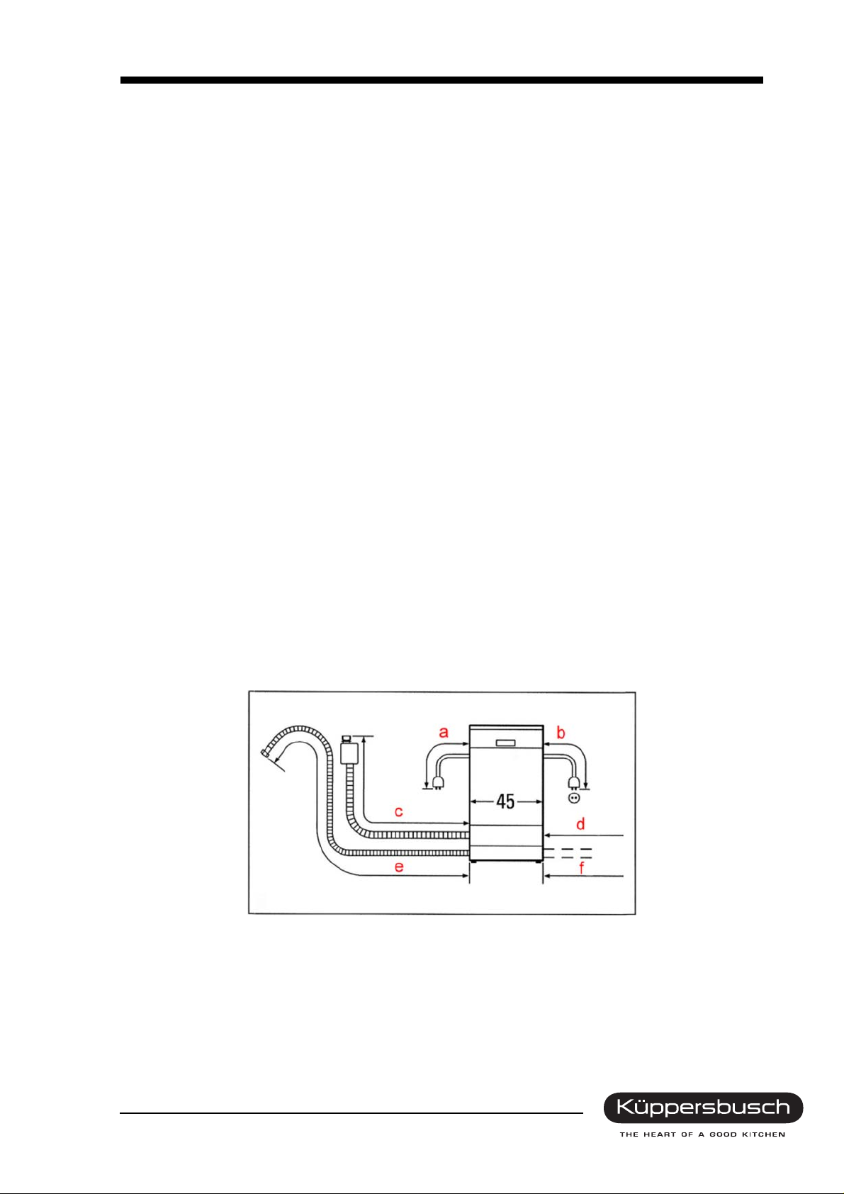
If the appliance is installed onto the drain with the standard length of hose, the max. permissible height
above the floor is 90 cm. If the discharge hose is extended , a max. height of 80 cm is not to be exceeded.
For the water supply (3/4"), a standard water pipe with water pressure of at least 0.5 bar (0.5 atmosphere
above atmospheric pressure) is required (when the water tap is open more than 8 l/min must flow out).
If the water pressure exceeds 10 bar (10 atmo sphere above atmosph eric pressure) a pressur e reducing
valve will have to be used. The appliances can be connected to a warm water supply of up to 60°C. It is
however recommendable to connect the appliance to a cold water supply (better drying and cleaning
results).
Connection dimensions for all dishwashers 45 cm
a = 1.4 m b = 1.7 m
c = 1.3 m (3.5 m with extension set) d = 1.4 m (3.6 m with extension set)
e = 1.5 m (3.5 m with extension set) f = 1.4 m (3.4 m with extension set)
For internal use only
8 Service Manual
4. Functional description of the single groups
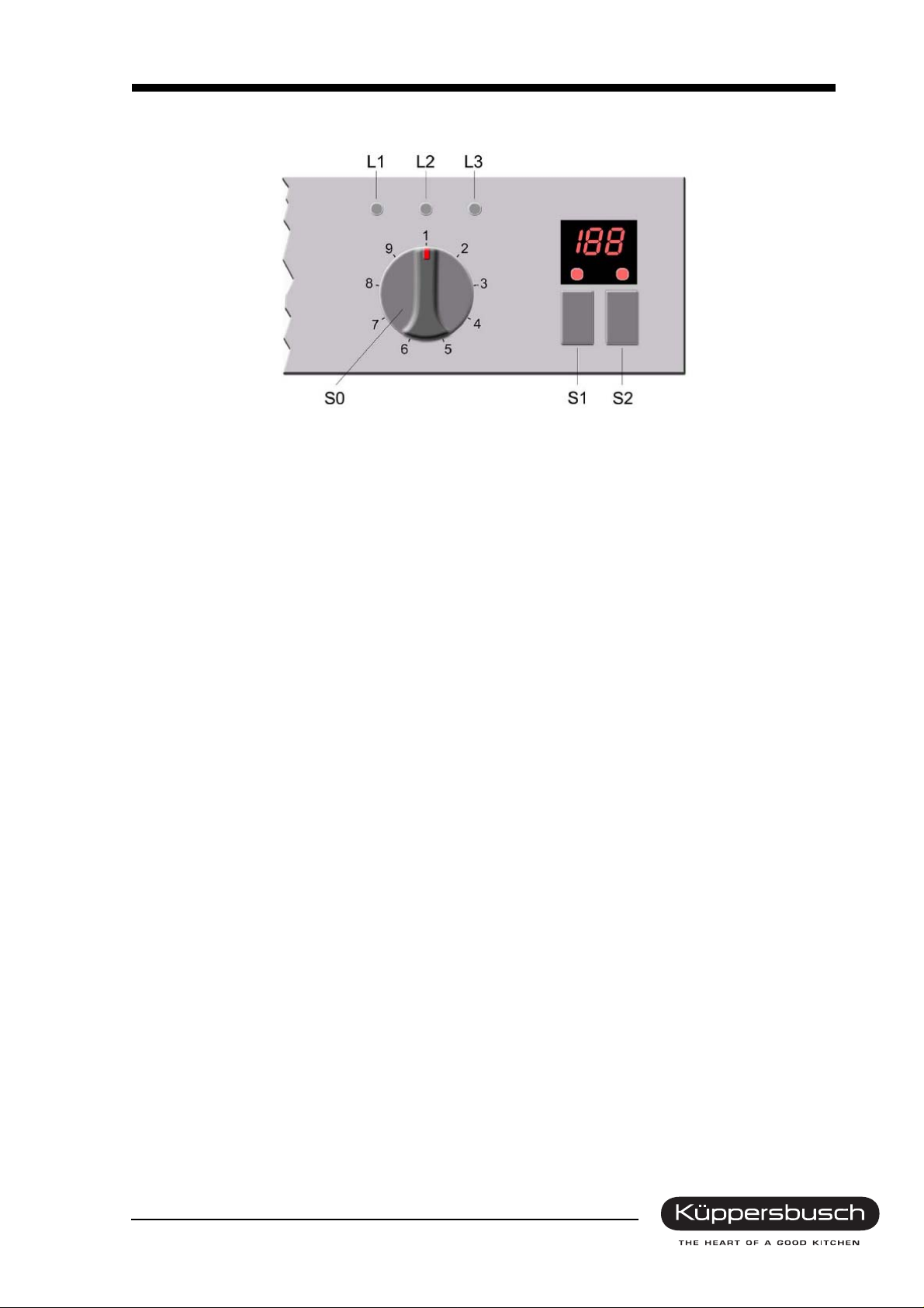
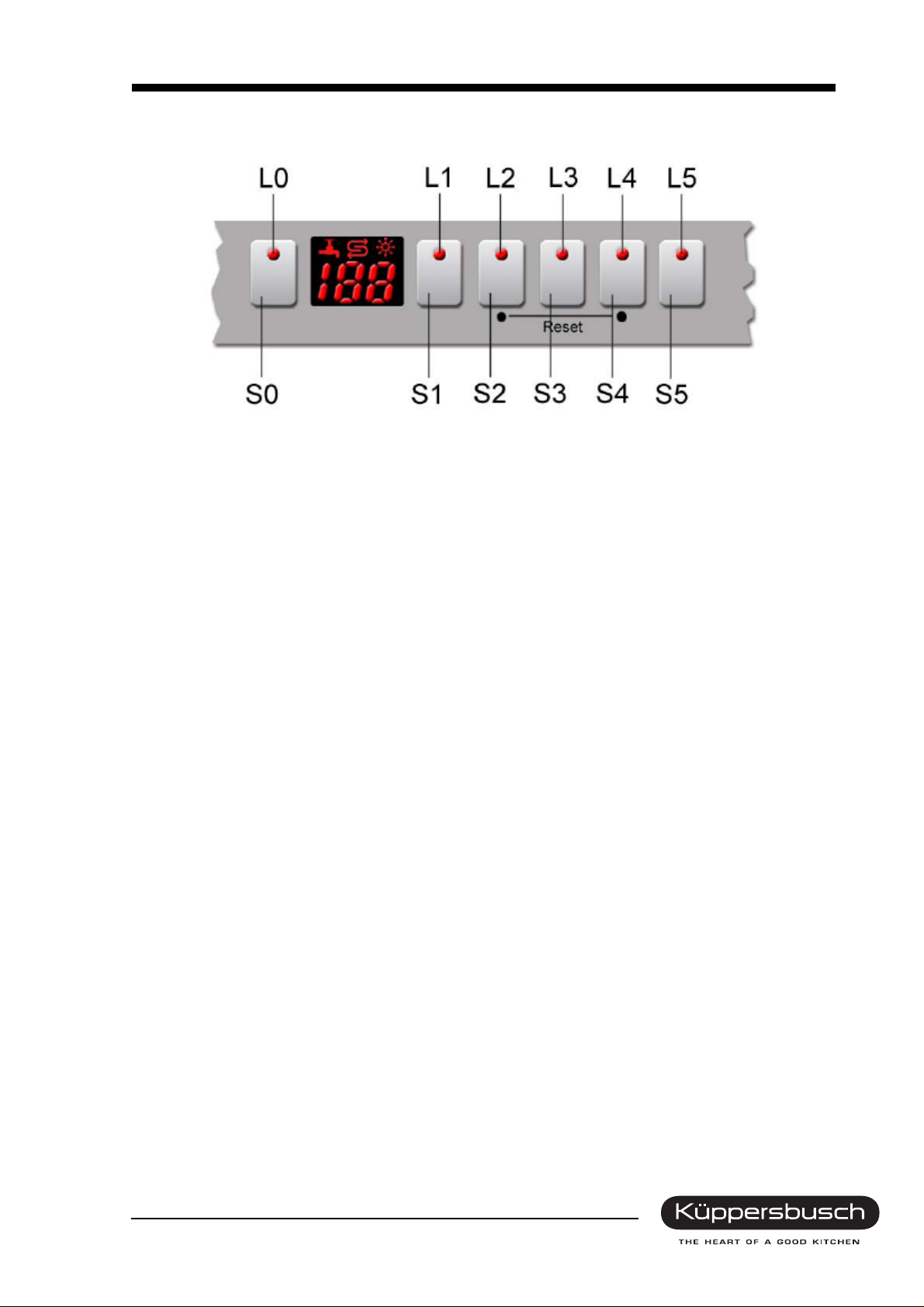
4.1 IGV 4... operation
4.1.1 Function
LEDs
• Program selection
• Clear rinse fill-up display
• Salt refill indicator
• End of program
Buttons / program selection
Intensive 70°
The program comprises a pre-rinse at 50°, a washing cycle at 70°, three intermediate rinses, a clear
rinse at 70° and a drying cycle.
Normal 65
The program comprises a pre-rinse cycle, a washing cycle at 65°, two intermediate rinses, a clear rinse
at 69° and a drying cycle.
ECO 50
The program comprises cleaning at 50°, an intermediate rinse, rinsing with a rinsing agent at 65°, and
drying.
Rapid 35
The program comprises cleaning at 35°, an intermediate rinse, rinsing with a rinsing agent at 55°, and
no drying.
Pre-wash
The program only comprises a cold rinse for the dishes.
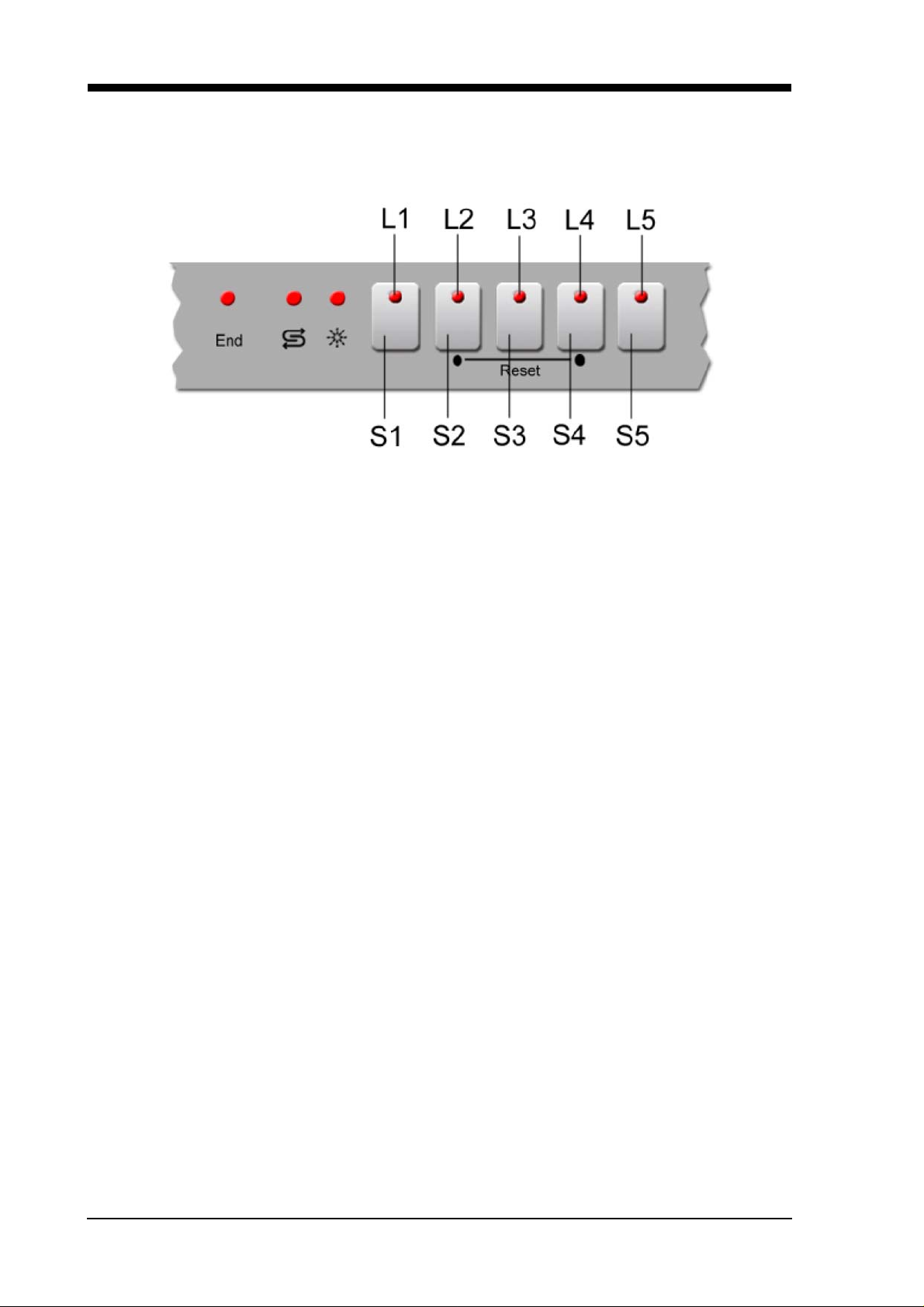
4.1.2 Program reset
With the appliance switched on, press the S2 button and the S4 button simultaneously for 3 sec. The
water will be pumped off for approx. one minute. The cleaning agent compartment should then be
closed, so that the dispensing device is also reset.
For internal use only
Service Manual 9
4.1.3 Special functions
Setting the hardness range
Keep the S3 button pressed and switch on the appliance. The LED for fill-up salt will blink. The fault is
indicated by means of the progra m LEDs (see ch art). The setting rises once every time the S3 button is
pressed. If the appliance is switched off, the setting is stored.
°dH °fH °Clarke mmol / l LEDs
L2 L3 L4
0 0 - 6 0 - 11 0 - 8 0 - 1.1 O O O
1 7 - 16 12 - 29 9 - 20 1.2-2.9 O O
2 17 - 21 30 - 37 21 - 26 3.0 - 3.7 O
3 22 - 35 38 - 60 27 - 44 3.8 - 6.2
Series setting = 2
4.1.4 General instructions on the controls
Tap closed
The appliance stops operating six minutes into the program procedure (filling position interrogation). In
the control, the selected program LED lights up constantly. The controls remain in this position until the
filling level has been reached.
Regeneration electronics system
On comparing the degree of water hardness set in the appliance, the electronics system determines
what quantity of water is possible before the water softener is exhausted. The quantity of water used is
calculated. Regeneration is carried out after the maximum number of rinses possible has been reached .
The discharge behaviour of the regeneration electronics system can be seen in the description under
initial operation / replacing the electronics unit.
Warm water recognition
If the water running in for the rinse with a rinsing agent has a temperature exceeding 45°C, the heat exchanger is not filled for the drying stage. In order to guarantee the di fference in temperature essential for
condensation, the temperature for the rinse with a rinsing agent is raised to 72 °C, thus increasing the
dishes own heat.
Memory electronics system
The electronics system has a memory store which registers the last program selected. Should no other
program be selected on program start-up, the program selected last will operate.
Power cut
The electronics system has a mains cut-off memory which ensures that a rinsing program that has been
commenced when a power failure occurs will be continued.
Sensors
All of the signals leaving the door switch, the level switch, the NTC sensor and the refill switches are
recorded and evaluated by the microprocessor at the respective point in time.
Consumers
Consumers such as valves, detergent and clear rins e disp enser s (actuators) ar e activate d by mea ns of
triacs. The circulation and the vacuation pump and the continuous flow heater are activated with relays.
For internal use only
10 Service Manual
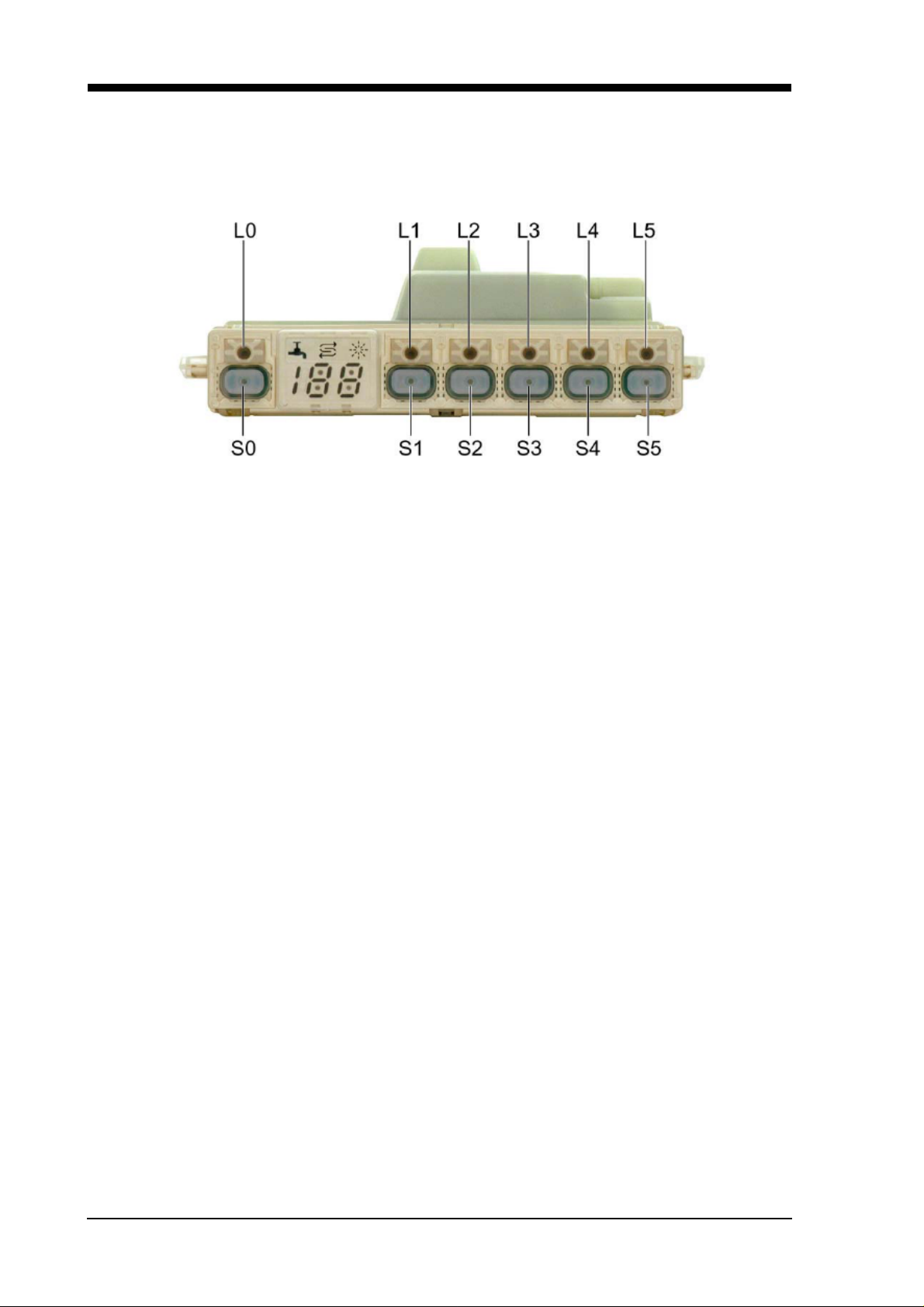
4.2 IG 4... operation
4.2.1 Function
LEDs
• Program selection
• Clear rinse fill-up display
• Salt refill indicator
• 2½ digit display
4.2.2 Pushbuttons
Pre-set time (ZVW)
The time-setting button enables the starting time to be postponed by up to 19 hours (setting between 0h
and 19h). The button must be pressed for at least one second.
Saving time
The rinsing program operation time can be shortened with the „time saver“ function. The consumption
of water and energy is raised so that the best results can be achieved while at the same time reducing
the operation time.
Display
The display comprises a 2½ digit 7-seg ment display, which also enables pr ogram times of more than
99 minutes to be shown. The remaining duration is recalculated at the end of the heating positions.
Should deviations result due to aqua sensor de cisions, the water intake temperature, the quantity of
dishes, etc., the remaining time displayed for these phases will be adjusted. Time differences of up to
60 minutes may hence result at the end of the washing and clear-rinse cycles.
For internal use only

Service Manual 11
4.2.3 Program dial
Intensive 70°
The program comprises a pre-rinse at 50°, a washing cycle at 70°, two intermediate rinses, a clear rinse
at 70° and a drying cycle.
Please ensure that rinsing is only carried out in the bottom basket until the required temperature
has been reached.
Auto 55° - 65° (depending on the model)
In the automatic program the aqua sensor not only decides on a change of water after the pre-rinse
cycle; it also determines the washing temperature and the number of intermediate rinses.
Aquasensor readings are classified into turbidity levels. Readings in the wash cycle decide on the washing temperature (from 45°C to 65°C) and the time after washing (from 5 to 30 minutes). Read ings taken
at the end of the wash cycle decide on the type of intermediate rinse and on how many intermediate
rinses are to be carried out.
Normal 65°
The program comprises a pre-rinse cycle, a washing cycle at 65°, two intermediate rinses, a clear rinse
at 66° and a drying cycle.
ECO 50°
The program comprises cleaning at 50°, an intermediate rinse, rinsing with a rinsing agent at 65°, and
drying. The aqua sensor is not activated in this program. Please ensure that rinsing is only carried out
in the bottom basket until the required temperature has been reached.
Gentle 40°
The program comprises a pre-rinse cycle, a washing cycle at 40°, an intermediate rinse, a clear rinse at
55° and a drying cycle.
Rapid 35°/45°
The program comprises a washing cycle at 35°/45°, one intermediate rinse, a clear rinse at 55° without
a drying cycle. The aqua sensor is not activated in this program.
Pre-wash
The program only comprises a cold rinse for the dishes. The aqua sensor is not activated in this program.
4.2.4 Display
The display comprises a 2½ digit 7-segment display, which also enables program times of more than
99 minutes to be shown. The remaining duration is recalculated at the end of the heating positions.
Should deviations result due to aqua sensor decisions, the water intake temperature, the quantity of
dishes, etc., the remaining time displayed for these phases will be adjusted. Time differences of up to
20 minutes may hence result at the end of the washing and clear-rinse cycles.
For internal use only
12 Service Manual
4.2.5 Program reset
With the appliance switched on, press the S2 button and the S4 button simultaneously for 3 sec. The
water will be pumped off for approx. one minute. The cleaning agent compartment should then be
closed, so that the dispensing device is also reset.
4.2.6 Special functions
Setting the hardness range
Keep the S3 button pressed and switch on the appliance. The setting will be shown in the display. The
setting rises once every time the S3 button is pressed. Once the setting h as reached 7, the i ndicator returns to 0. When the appliance is switched off, the setting is stored.
°dH °fH °Clarke mmol / l
0-6 0-11 0-8 0-1.1 --- 0
7-8 12-15 9-10 1.2-1.4 4 1
9-10 16-17 11-12 1.5-1.8 7 2
11-12 18-21 13-15 1.9-2.1 9 3
13-16 22-29 16-20 2.2-2.9 14 4
17-21 30-37 21-26 3.0-3.7 18 5
22-30 38-54 27-38 3.8-5.4 27 6
31-50 55-89 39-62 5.5-8.9 54 7
Salt quantity
in g per rinse
Setting
Series setting = 4
Setting Intensive drying
Keep the S2 button pressed and switch on the appliance. 0 will appear on the number indicator. By
pressing the S2 button once again, 1 will appear on the display, meaning that the intensive drying program is switched on. If the appliance is switched off, the setting is stored. Activating intensive drying raises the temperature by 3K in the rinse program with a rinsing agent.
4.2.7 General instructions on the controls
Tap closed
The appliance stops operating six minutes into the program procedure (filling position interrogation). The
remaining operating period is indicated as before in the display. The controls remain in this position until
the filling level has been reached.
Regeneration electronics system
On comparing the degree of water hardness set in the applia nce, the electronics system determines the
number of rinses which are possible until the softening device has been exhausted. The quantity of water
used is calculated. Regeneration is carried out after the maximum number of rinses possible has been
reached.
The discharge behaviour of the regeneration electronics system can be seen in the description under
“Initial operation / electronics exchange”.
For internal use only
Service Manual 13
Warm water recognition
If the water running in for the rinse with a rinsing agent has a temperature exceeding 45°C, the heat ex-
changer is not filled for the drying stage. In order to guarantee the di fference in temperature essential for
condensation, the temperature for the rinse with a rinsing agent is raised to 72 °C, thus increasing the
dishes own heat.
Memory electronics system
The electronics system has a memory store which registers the last program selected. Should no other
program be selected on program start-up, the program selected last will operate.
Power cut
The electronics system has a mains cut-off store which ensures that a rinsing program that has been
commenced when a power failure occurs will be continued.
Sensors
All of the signals leaving the door switch, the level switch, the NTC sensor and the refill switches are
recorded and evaluated by the microprocessor at the respective point in time.
Consumers
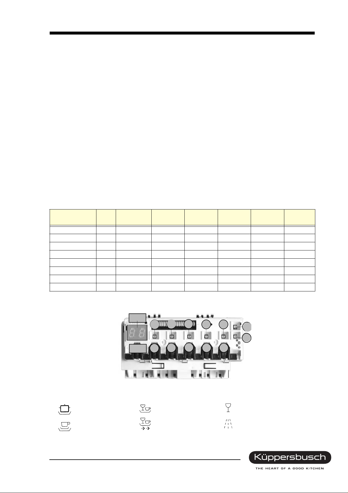
Consumers such as valves, detergent and clear rinse
dispensers (actuators) are activated by means of tri-
acs (see photo). The circulation and the vacuation
pump and the continuous flow heater are activated
with relays.
A* = Filling valve
A* = Dispenser
A* = Water diverter
B = Filling level
C = Drain valve heat exchanger
D = Regeneration valve
E = Filling level
* = Triple triac
For internal use only

14 Service Manual
List of triacs
R5 = Filling level
R6 = Filling level
TY6 = Drain valve heat exchanger
TY7 = Dispenser actuator
TY8 = Regeneration valve
TY9 = Filling valve
TY11 = Actuator top basket valve / Water diverter
When a module is replaced due to a defective triac it
is essential to check the component selected too.
Face
Rear
For internal use only
Service Manual 15
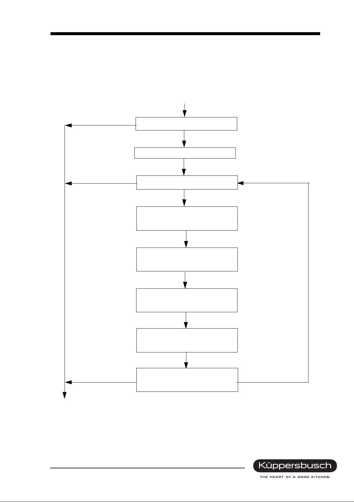
4.3 Initial operation / electronics exchange
In the case of initial operation or electronics exchange, the following program procedure is to be ob-
served. (Program counter = 0!)
Procedure for initial start-up - appliances with a heat exchanger
PC > 0
Lack of salt = Off
Program counter (PC)
Pump 15 sec.
Salt refill indicator
Lack of salt = On
Pre-fill heat exchanger
to F1
Pump + drain
70 sec.
PC => 3
Start of the rinsing program
Regeneration
60 sec.
Cycle counter
raise by 1
Counter
check
PC < 3
For internal use only
16 Service Manual
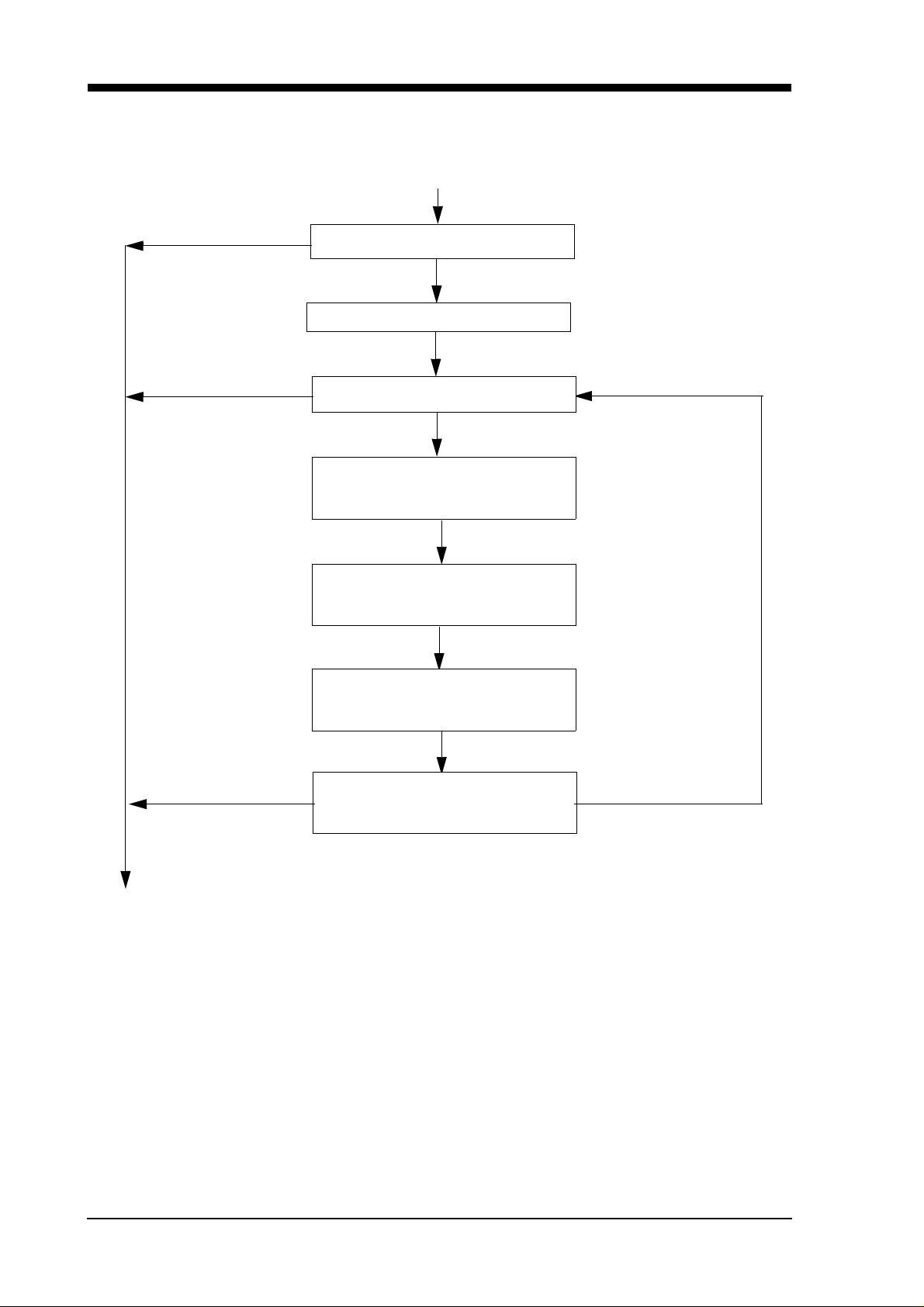
Procedure for initial start-up - appliances without a heat exchanger
PC > 0
Lack of salt = Off
Program counter (PC)
PC = 0
Pump 15 sec.
Salt refill indicator
Lack of salt = On
Filling valve on,
10 sec.
Regeneration
60 sec.
PC => 3
Start of the rinsing program
Cycle counter
raise by 1
Counter
check
PC < 3
For internal use only
Service Manual 17
4.4 IG 458.1E operation
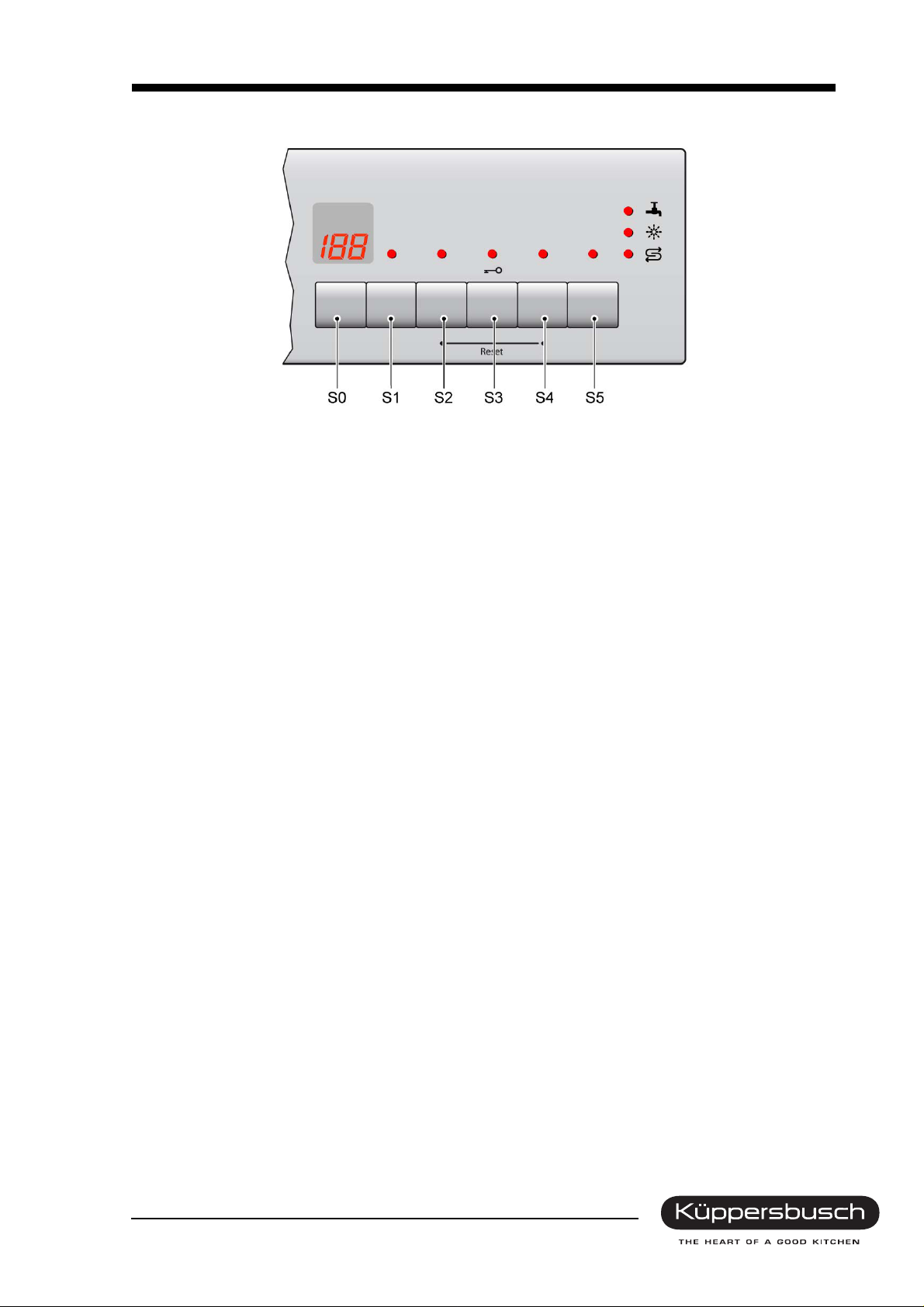
4.4.1 LEDs
• Tap closed
• Salt refill indicator
• Clear rinse fill-up display
• Additional functions
• 2½ digit display
4.4.2 Main switch
The main switch is located on the left-hand side, separate from the electronic unit.
4.4.3 Pushbuttons / additional functions
Pre-set time (PST)
The time-setting button enables the starting time to be postponed by up to 24 hours.
Soaking (optional)
The button for soaking can be pressed as a supplement to any program. When the button is pressed,
an additional pre-rinse program with heating up to 55° will take place in the lower basket, resulting in an
extension of the program time of approx. 20 min. This function is recommended for washing various
types of dishes (top basket: sensitive dishes / bottom basket extremely dirty robust dishes).
Vario speed (optional)
The Vario speed function reduces the program running time with a higher water and energy consump-
tion. This is achieved by using more water in the rinse cycle and with water points with two-basket func-
tion.
Half load (optional)
The “Half Load” function reduces water consumption and the running time. Ba sically this is achieved by
passing over the prerinse and the second intermediate rinse cycle.
For internal use only
18 Service Manual
4.4.4 Deactivating the clear rinse refill display
Press the S1 button and keep it pressed. Switch on the appliance. The display will indicate 1. By pressing
the S1 button once again, 0 will appear on the display, meaning that the clear rinse fill-up display is deactivated.
0 = off
1 = on
If the appliance is switched off, the setting is stored. Deactivating the refill clear rinse display will raise
the temperature for the clear rinse by 3K in order to achieve better drying results (see too 3 in 1 detergent
recognition).
4.4.5 Reset
Resetting is done with an additional position of the rotary switch for th ese dishwashers. T his means that
a reset commences 3 seconds after the switch is moved into this position.
Water is drained off for one minute and the electronic system will then be ready for a new program.
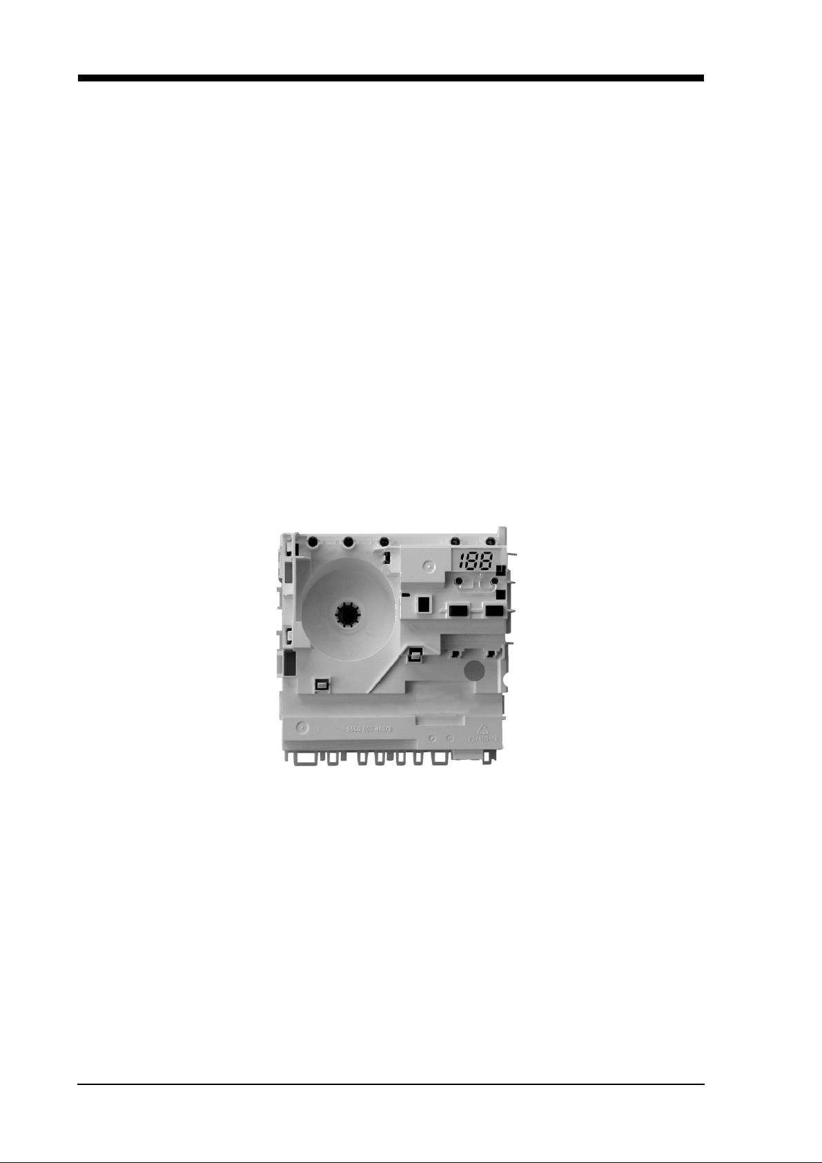
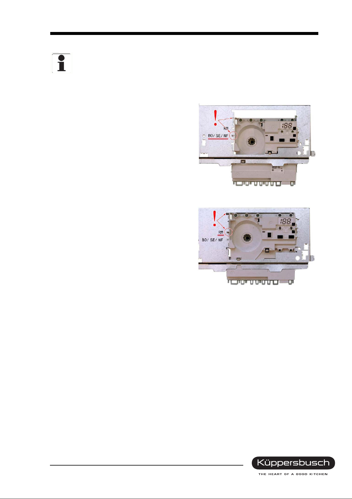
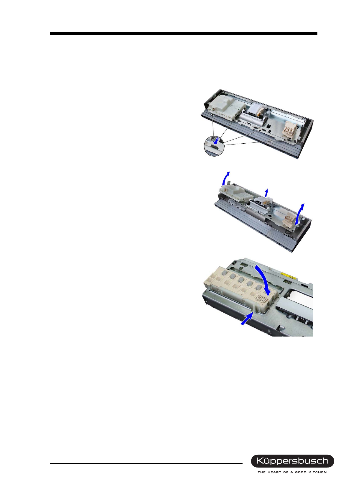
4.5 Construction components
4.5.1 Module
For internal use only
Service Manual 19
Mounting the module
If the module is not installed in the proper position, the light conductors in the panel
may be severed.
The brand determines the position of the module in the support plate. There are two positions:
At the bottom of the support plate
The module is fastened at the points shown.
At the top of the support plate
The module is fastened at the points shown.
4.5.2 Water intake
The dishwasher detects that the tap has been closed when the flow sensor receives no signal for
30seconds.
4.5.3 Consumers
Consumers such as valves, detergent and clear rinse dispensers and the circulation pump are activated
by means of triacs (see the list of triacs). The evacuation pump and the continuous flow heater are acti-
vated with relays.
For internal use only
20 Service Manual
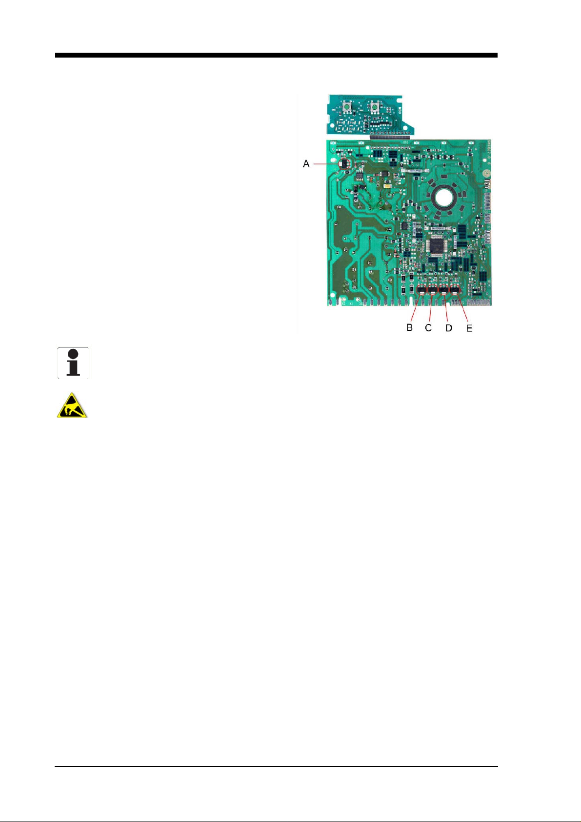
4.5.4 List of triacs
When a module is replaced due to a defective triac it
is essential to check the component selected too.
A = Dispenser actuator
B = Water diverter
C = Filling level
D = Regeneration valve
E = Drain valve heat exchanger
Start up the customer service program before replacing any modules.
Components may be electrostatic!
Instructions on electrostatic hazards are to be observed before a module is replaced.
For internal use only
Service Manual 21
4.6 IG 4406.0E operation
4.6.1 LEDs
• Tap closed
• Salt refill indicator
• Clear rinse fill-up display
• Additional functions
• 2½ digit display
4.6.2 Buttons / program selection
Pre-set time (PST)
The time-setting button enables the starting time to be postponed by u p to 19 hours (setting between 0h
and 19h). The button must be pressed for at least one second.
Saving time (optional)
The rinsing program operation time can be shortened with the „time saver“ function. The consumption
of water and energy is raised so that the best results can be achieved while at the same time reducing
the operation time.
Half load (optional)
The “Half Load” function reduces water consumption and the running time. Ba sically this is achieved by
passing over the prerinse and the second intermediate rinse cycle.
Vario speed (optional)
The “Vario speed” function reduces the program running time with a higher water and energy consump-
tion. This is achieved by using more water in the rinse cycle and with water points with two-basket func-
tion.
Intensive 70° / Power 75°
The program comprises a pre-rinse at 50°, a washing cycle at 70°, two intermediate rinses, a clear rinse
at 70° and a drying cycle.
For internal use only
22 Service Manual
4.7 Construction components
4.7.1 Module
The electronics system comprises two modules installed in a cab inet. The control/output module is connected to the operating/indicating module by means of a flat cable.
Tap closed
If the level is not reached after 6 minutes in the filling position:
• The „check water intake“ LED will be activated (optional)
• The program will be discontinued (pumping for 60 sec.)
• The program will be re-started.
The procedure will be repeated twice if the level is still not reached. The controls will then remain in this
position until the filling level has been reached. The remaining time which is still left will be maintained.
Regeneration electronics system
On comparing the degree of w ater hardness set in the appliance, the electronics system determines
what quantity of water is possible before the water softener is exhausted.
The quantity of water used is calculated. Regeneration is carried out after th e maximum number of rinses
possible has been reached.
The discharge behaviour of the regeneration electronics system can be seen in the description under
initial operation / replacing the electronics unit.
Warm water recognition
If the water running in for the rinse with a rinsing agent has a temperature exce eding 45°C, the heat exchanger is not filled for the drying stage. In order to guarantee the difference in temperature essential for
condensation, the temperature for the rinse with a rinsing agent is raised to 72°C, thus increasing the
dishes own heat.
Memory electronics system
The electronics system has a memory store which registers the last program selected. Should no other
program be selected on program start-up, the program selected last will operate.
For internal use only
Service Manual 23
4.7.2 Disassembling the module
1. Remove the furniture front (if fitted).
2. Remove outer door.
3. Disconnect support plate with the fascia from the inner door.
4. Disengage the four catches on the fascia from
the support plate.
5. Tilt support plate away from the fascia.
6. Disengage catches on the module housing from
the support plate.
7. Pull module down out of the support plate.
8. Remove plugs from the module, plugs are
coded.
4.7.3 Mounting the module
1. Connect plugs from the cable harness to the module.
2. Push module into the control panel frame until the module is held firmly in place by the catches.
3. Attach support plate to the inner door.
4. Attach fascia from above into the support plate and tilt down until the four catches lock.
5. Attach outer door.
6. Attach furniture front (if fitted).
For internal use only
24 Service Manual
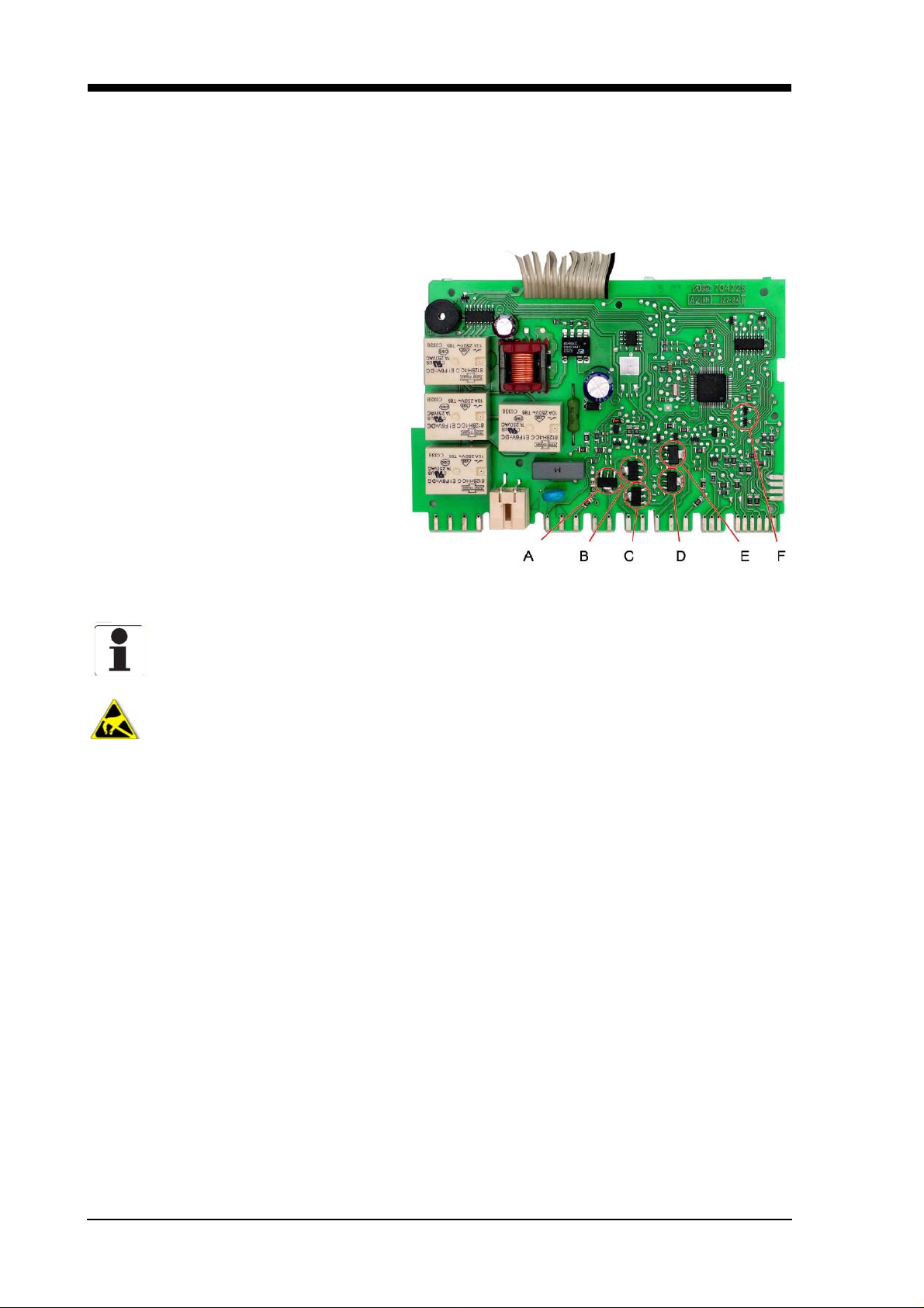
4.7.4 Consumers
Consumers such as valves, detergent and clear rinse dispensers (actuators) are activated by means of
triacs. The circulation and the vacuation pump and the continuous flow heater are activated with relays.
4.7.5 List of triacs
When a module is replaced due to a defective triac it is essential to check the component selected too.
A = Dispenser actuator
B = Drain valve heat exchanger
C = Regeneration valve
D = Filling level
E = Water diverter
F = Info light (optional)
Start up the customer service program before replacing any modules.
Components may be electrostatic!
Instructions on electrostatic hazards are to be observed before a module is replaced.
For internal use only
Service Manual 25
4.8 IGV 4408.0 operation
4.8.1 LEDs
• Program selection
• Check water intake (optional)
• Clear rinse fill-up display
• Salt refill indicator
• 2½ digit display
4.8.2 Buttons / program selection
Pre-set time (PST)
The time-setting button enables the starting time to be postponed by u p to 19 hours (setting between 0h
and 19h). The button must be pressed for at least one second.
Saving time (optional)
The rinsing program operation time can be shortened with the „time saver“ function. The consumption
of water and energy is raised so that the best results can be achieved while at the same time reducing
the operation time.
Half load (optional)
The “Half Load” function reduces water consumption and the running time. Ba sically this is achieved by
passing over the prerinse and the second intermediate rinse cycle.
Vario speed (optional)
The “Vario speed” function reduces the program running time with a higher water and energy consumption. This is achieved by using more water in the rinse cycle and with water points with two-basket function.
Intensive 70° / Power 75°
The program comprises a pre-rinse at 50°, a washing cycle at 70°, two intermediate rinses, a clear rinse
at 70° and a drying cycle.
For internal use only
26 Service Manual
4.9 Construction components
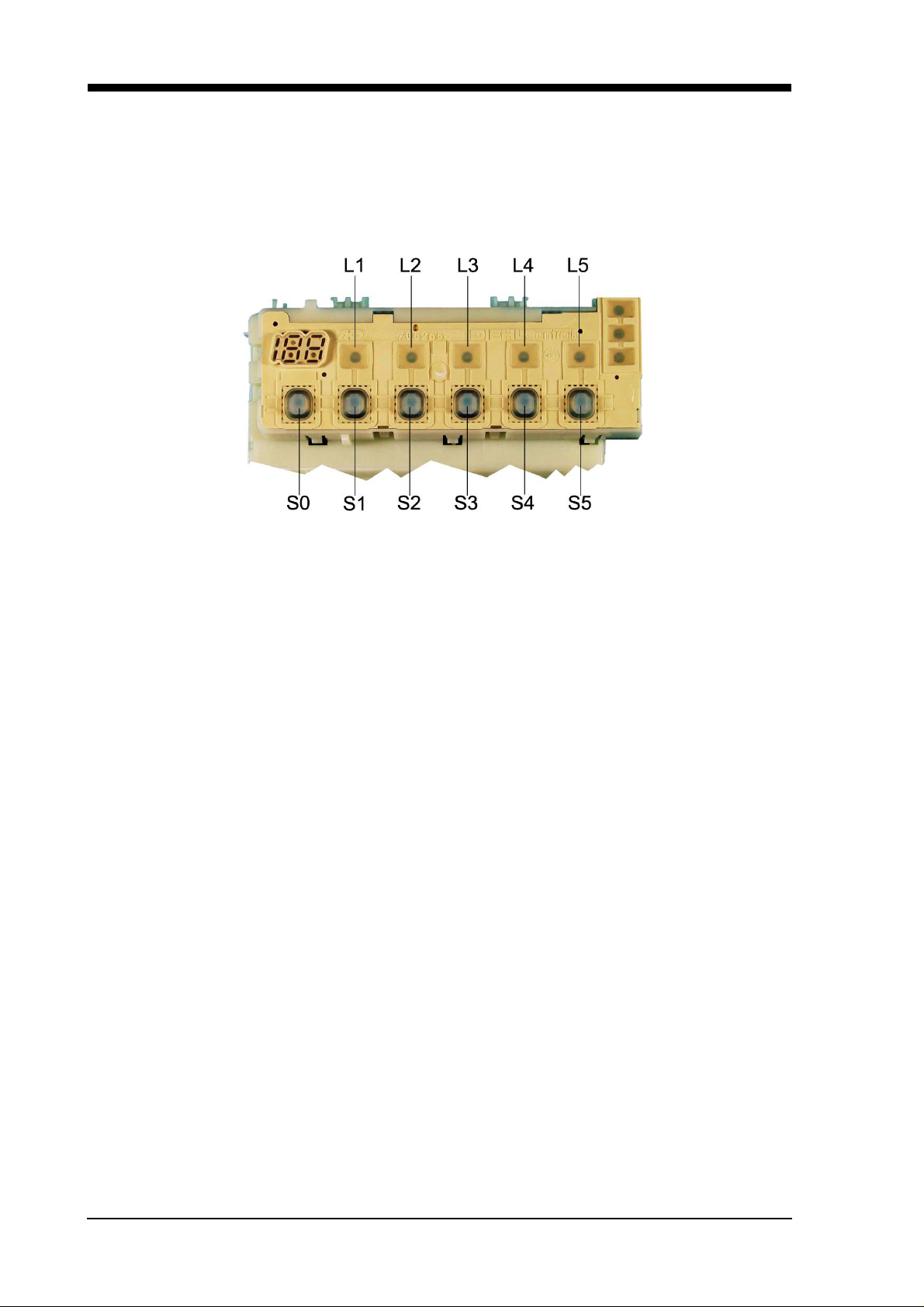
4.9.1 Module
Tap closed
If the level is not reached after 6 minutes in the filling position:
• The „check water intake“ LED will be activated (optional)
• The program will be discontinued (pumping for 60 sec.)
• The program will be re-started.
The procedure will be repeated twice if the level is still not reached. The controls will then remain in this
position until the filling level has been reached. The remaining time which is still left will be maintained.
Regeneration electronics system
On comparing the degree of w ater hardness set in the appliance, the electronics system determines
what quantity of water is possible before the water softener is exhausted.
The quantity of water used is calculated. Regeneration is carried out after th e maximum number of rinses
possible has been reached.
The discharge behaviour of the regeneration electronics system can be seen in the description under
initial operation / replacing the electronics unit.
Warm water recognition
If the water running in for the rinse with a rinsing agent has a temperature exce eding 45°C, the heat exchanger is not filled for the drying stage. In order to guarantee the difference in temperature essential for
condensation, the temperature for the rinse with a rinsing agent is raised to 72°C, thus increasing the
dishes own heat.
Memory electronics system
The electronics system has a memory store which registers the last program selected. Should no other
program be selected on program start-up, the program selected last will operate.
Power cut
The electronics system has a mains cut-off store which ensures that a rinsing program that has been
commenced when a power failure occurs will be continued.
For internal use only

Service Manual 27
4.9.2 Disassembling the module
1. Remove the furniture front (if fitted).
2. Remove outer door.
3. Loosen the support plate and tilt it forwards.
4. Press the two catches on the module holder outwards and remove the module from the control
panel frame.
5. Remove plugs from the module; plugs are
coded.
The program buttons are to be taken out of the old module and inserted in the new
module before the module is replaced.
4.9.3 Mounting the module
1. Connect plugs from the cable harness to the module.
2. Push the module into the control panel frame until the module is held firmly in place by the two
catches.
3. Mount the support plate.
4. Attach outer door.
5. Attach furniture front (if fitted).
4.9.4 Sensors
All of the signals leaving the door switch, the level switch, the NTC sensor and the refill switches are
recorded and evaluated by the microprocessor at the respective point in time.
For internal use only

28 Service Manual
4.9.5 Activating the consumers
Consumers such as valves, detergent
and clear rinse dispensers (actuators)
are activated by means of triacs (see
photo). The circulation pump, the evacuation pump and the continuous flow heater are activated with relays.
When a module is replaced due to a defective triac it is essential to check the
component selected too.
A = Dispenser actuator
B = - - C = Regeneration valve
D = Filling valve
E = Water diverter
F = Info light (optional)
Start up the customer service program before replacing any modules.
Components may be electrostatic!
Instructions on electrostatic hazards are to be observed before a module is replaced.
For internal use only
Service Manual 29
5. Explanation of the rinsing instructions
5.1 Coding instructions for an electronics system with G controls
IG 4...
Subsequent to an exchange of the electronic controls which are installed as a standard, the controls
have to be coded again with the appliance programs (see table).
Note: In the case of appliances with 3 or 4 programs/buttons, the control system must be programmed
prior to fitting the panel cover.
1. Instruction
Press the buttons S2, S3, S4 and S5 simultaneously, keep them pressed and activate the main
switch. The L2 to L5 LEDs will blink as long as the S2 to S5 buttons are being pressed.
Subsequent to releasing the buttons S2 to S5, the curr ent coding will be indi cated as a code on the
display (see code chart).
2. Setting the type of code
By pressing the S2 button the various variant codes (see chart) can be set.
3. Storing the coding
On switching off the appliance, the variant/code is stored.
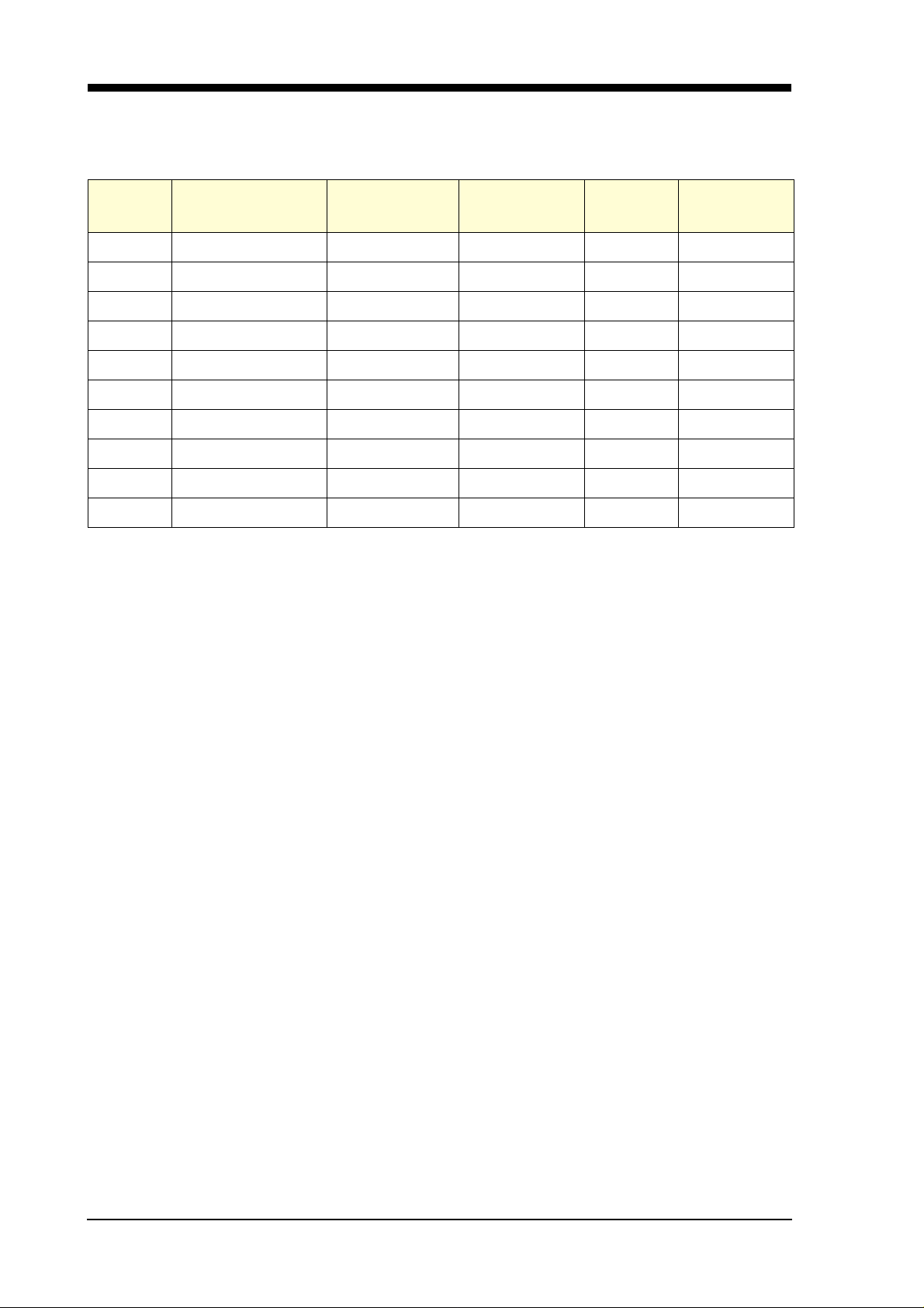
Code table
Code indication
in the display
20 PST Intensive 70° Normal 65° ECO 50° Rapid 35° Pre-wash 0
21 PST UB Normal 65° ECO 50° Rapid 35° Pre-wash 1
22 PST Normal 65° ECO 50° Rapid 35° Pre-wash 2
23 PST UB Normal 65° ECO 50° Pre-wash 3
24 PST Normal 65° ECO 50° Pre-wash 4
25 PST Normal 65° ECO 50° Gentle 40° Rapid 35° 5
26 PST Normal 65° ECO 50°* Rapid 35° Pre-wash 6
27 PST Intensive 70° Normal 65° ECO 50°* Rapid 35° Pre-wash 7
S0 S1 S2 S3 S4 S5
PST = Pre-set time UB = Upper basket rinse *= Energy label A-B-D
Display
PST
L 1 L 2 L 3 L 4 L 5
S 1S 2S 3S 4S 5
L 7
L 6
Button
Coding
Program symbols
Intensive 70°
Normal 65°
For internal use only
ECO 50°
Rapid 35°
Gentle 40°
Pre-rinse
30 Service Manual
5.2 Customer service test program: G controls (with heat exchanger)
No.: 5600 009 884 (Abbreviations see see “Abbreviations / terms” on page 36)
INDEX Function Temperature Time [s] Sensor Filling volume
DB / UB
0P 30
1PF F1
2F 3.9 / 3.3
3 C + H + TR1 + TR2 max. 72°C
4 C + H + D max. 72°C 120
5C + H 65°C
6 C + H + RE max. 72°C 120
7P 60
8R + DR 60
9P + DR 30
The customer service special program has been selected if the S2 and S4 buttons are pressed when
switching on the dishwasher at the main switch.
The following will be indicated on the control panel:
- LEDs L2 and L4 are flashing.
- As long as both the S2 and S4 buttons are kept pressed after switching on the appliance, the variant coding will be indicated.
e.g. : 20 = variant 0
21 = variant 1, and so on.
- The respective LED will light up when one of the program buttons is pressed.
- On pressing the S3 button, the display and the fault indicator LEDs will also light up.
- On pressing the pre-set time button, an 8h will light up in the 7-segment display.
The customer service program is started when the S2 and S4 buttons ar e pressed. No pr e-set time is
possible, and the customer service special program is ended when the main switch is switched off.
- The error number is indicated on the display:
1 = aqua sensor defect (Note: Indication even if there is no aqu a sensor!)
2 = heating error
3 = fault combination of fault 1 + fault 2
4 = filling error
5 = fault combination of fault 1 + fault 4
8 = NTC fault (interruption or short circuit)
9 = fault combination of fault 1 + fault 8
In the case of a fault combination, the figures are added accordingly.
The upper basket function is activated for the entire program procedure. The next step in the program
can be started when the S3 button is activated. If the heating stage is skipped, a heating fault will be
indicated. (Exception: In t he filling stage it is only possible to continue to the next stage by means
of the filling switch F1)
For internal use only
 Loading...