

kunzel TS 614 Installation And Operating Manual
Installation and operating manual
Type 614 microprocessor control panel
for KÜNZEL wood gasification boiler type HV and HV-S
TS614_1_32, February 12, 2009

Contents
1 General information about the type 614 microprocessor control panel 4
1.1 Product contents . . . . . . . . . . . . . . . . . . . . . . . . . . . . . . . . . . . . . . . 4
1.2 Disposal of old unit . . . . . . . . . . . . . . . . . . . . . . . . . . . . . . . . . . . . . 4
1.3 Safety advice and general information about operation . . . . . . . . . . . . . . . . . . 4
2 Installation 5
2.1 Installation of the control panel on the boiler . . . . . . . . . . . . . . . . . . . . . . . . 5
2.2 Electrical installation . . . . . . . . . . . . . . . . . . . . . . . . . . . . . . . . . . . . 5
2.2.1 Connecting sensors, control and mains power cables . . . . . . . . . . . . . . . 6
3 Indicators and controls 8
4 The menu 9
4.1 Design . . . . . . . . . . . . . . . . . . . . . . . . . . . . . . . . . . . . . . . . . . . . 9
4.2 Boiler sub-menu . . . . . . . . . . . . . . . . . . . . . . . . . . . . . . . . . . . . . . . 11
4.2.1 Buffer tank min. temperature . . . . . . . . . . . . . . . . . . . . . . . . . . . . 11
4.2.2 Buffer tank monitoring system . . . . . . . . . . . . . . . . . . . . . . . . . . . 11
4.2.3 Changeover point . . . . . . . . . . . . . . . . . . . . . . . . . . . . . . . . . . 12
4.2.4 Ignition period . . . . . . . . . . . . . . . . . . . . . . . . . . . . . . . . . . . 12
4.2.5 Burn-out time . . . . . . . . . . . . . . . . . . . . . . . . . . . . . . . . . . . . 12
4.2.6 Pump mode . . . . . . . . . . . . . . . . . . . . . . . . . . . . . . . . . . . . . 12
4.2.7 Fans . . . . . . . . . . . . . . . . . . . . . . . . . . . . . . . . . . . . . . . . . 13
4.2.8 Start Mode . . . . . . . . . . . . . . . . . . . . . . . . . . . . . . . . . . . . . 13
4.2.9 Exhaust gas sensor . . . . . . . . . . . . . . . . . . . . . . . . . . . . . . . . . 13
4.2.10 Exhaust gas factor . . . . . . . . . . . . . . . . . . . . . . . . . . . . . . . . . 13
4.2.11 Start exhaust gas . . . . . . . . . . . . . . . . . . . . . . . . . . . . . . . . . . 13
4.2.12 Service . . . . . . . . . . . . . . . . . . . . . . . . . . . . . . . . . . . . . . . 13
4.3 Display sub-menu . . . . . . . . . . . . . . . . . . . . . . . . . . . . . . . . . . . . . . 14
4.3.1 Language: . . . . . . . . . . . . . . . . . . . . . . . . . . . . . . . . . . . . . . 15
4.3.2 Timeout: . . . . . . . . . . . . . . . . . . . . . . . . . . . . . . . . . . . . . . 15
4.3.3 Date and time: . . . . . . . . . . . . . . . . . . . . . . . . . . . . . . . . . . . 15
4.4 Info sub-menu . . . . . . . . . . . . . . . . . . . . . . . . . . . . . . . . . . . . . . . . 15
4.5 Outside temperature control unit and other auxiliary modules sub-menu . . . . . . . . . 15
5 Mode of operation and control 15
5.1 General information . . . . . . . . . . . . . . . . . . . . . . . . . . . . . . . . . . . . . 15
5.2 Pump protection . . . . . . . . . . . . . . . . . . . . . . . . . . . . . . . . . . . . . . . 15
5.3 Frostguard . . . . . . . . . . . . . . . . . . . . . . . . . . . . . . . . . . . . . . . . . . 16
5.4 The operating modes . . . . . . . . . . . . . . . . . . . . . . . . . . . . . . . . . . . . 16
5.5 Start . . . . . . . . . . . . . . . . . . . . . . . . . . . . . . . . . . . . . . . . . . . . . 16

5.5.1 Manuel firing . . . . . . . . . . . . . . . . . . . . . . . . . . . . . . . . . . . . 17
5.5.2 Electrical firing . . . . . . . . . . . . . . . . . . . . . . . . . . . . . . . . . . . 17
5.5.3 Automatical . . . . . . . . . . . . . . . . . . . . . . . . . . . . . . . . . . . . . 17
5.5.4 Date . . . . . . . . . . . . . . . . . . . . . . . . . . . . . . . . . . . . . . . . . 17
5.6 Operating . . . . . . . . . . . . . . . . . . . . . . . . . . . . . . . . . . . . . . . . . . 18
5.7 Adding fuel logs while the boiler is operating . . . . . . . . . . . . . . . . . . . . . . . 18
5.8 Aborting heating procedure . . . . . . . . . . . . . . . . . . . . . . . . . . . . . . . . 19
5.9 Detection of smouldering and behaviour upon overheating . . . . . . . . . . . . . . . . 19
5.10 Burnout . . . . . . . . . . . . . . . . . . . . . . . . . . . . . . . . . . . . . . . . . . . 19
6 Combination with other modules 20
7 Software Update 22
8 Operational malfunctions, fault messages 22
9 Maintenance and cleaning 25
10 Technical data 25
10.1 Electrical data . . . . . . . . . . . . . . . . . . . . . . . . . . . . . . . . . . . . . . . . 25
10.2 Sensors . . . . . . . . . . . . . . . . . . . . . . . . . . . . . . . . . . . . . . . . . . . 26
10.3 Other information . . . . . . . . . . . . . . . . . . . . . . . . . . . . . . . . . . . . . . 26
3

1 General information about the type 614 microprocessor control panel
1.1 Product contents
Please ensure that the contents of the control panel delivery box are complete:
• 1 x control panel
• 1 x boiler sensor, yellow, 1 x buffer tank sensor, blue, 1 x buffer tank sensor, red
• 1 x connector socket, white, 3-pole, 1 x connector plug, white 3-pole, 1 x connector socket, brown,
3-pole, 1 x connector plug, black, 4-pole
• 2 x cable ties, 2 x sensor plugs 10-pole
1.2 Disposal of old unit
The boilers supplied by KÜNZEL are stationary units that comply with the WEEE Directive. The
electrical and electronic components contained in the boilers do not fall within the remit of this directive
and will therefore not be taken back by KÜNZEL.
Old units still contain valuable raw materials. For this reason, return them to your dealer or take them to
your local recycling depot. Render the mains power connection unusable beforehand in order to prevent
misuse. The manufacturer cannot be held responsible for damage caused by non-compliance with the
safety advice and improper use.
1.3 Safety advice and general information about operation
Before commissioning the control unit, please read carefully the operating manual for the control
panel. Keep it in a place where it is readily available. Never pass on the units to other persons without
also providing them with the operating manual. The manufacturer is not responsible for improper or
unintended usage of this equipment. This unit complies with the statutory safety regulations. Improper
usage can cause damage to persons and property. The type 614 microprocessor control panel is only
intended for use with type HV and HV-S KÜNZEL-wood gasification boilers. The use of this control
panel in any other type of application is at one’s own risk. The manufacturer is not responsible for
damage caused by mis-operation of the unit or any usage other than its intended purpose. The application
of the control unit is the responsibility of the installation company. Please address any queries to your
heating installer.
Ensure that unauthorised persons, in particular children, do not have access to the control unit and
the heating system. Ensure that children cannot touch the control panel or the boiler while they are in
operation! Caution, risk of burns!
4

Only use the control unit in its properly installed state in order to ensure that no electrical components
can be touched.
Before starting to work on the boiler fan or any of the other 240 volt connections in the control panel,
the control panel is to be (all pole) disconnected from the mains power supply.
The unit is only electrically disconnected from the power utility grid (mains power supply) when one of
the following conditions has been met:
- The power supply cable has been disconnected from the power utility grid by an isolating switch.
Exercise caution if an external heating system is present. Ensure that this has also been disconnected
from the mains power supply.
- The circuit breaker of the local electrical installation has been switched off.
- The screw-type fuse of the local electrical installation has been removed completely.
Only the manufacturer or KÜNZEL’sauthorised customer service provider is permitted to open the unit.
2 Installation
2.1 Installation of the control panel on the boiler
For further information about this, please read the instructions for the wood gasification boiler.
2.2 Electrical installation
• The electrical supply may only be connected by a qualified electrician.
• The relevant regulations pertaining to electrical installations (VDE) and the supplementary regu-
lations laid down by the local electricity / utility companies are to be observed.
• The unit complies with the EC EMC directives.
• The unit may only be connected to an electrical system that complies with VDE 0100 (in Austria
ÖVE-EN 1)
• Before connecting the control unit, compare the connection requirements (voltage and frequency)
against those of the power utility grid. It is essential that these requirements are identical. If in
doubt, please contact your electrician.
• Only permit the microprocessor control panel to be installed by a person with the necessary expertise or training using suitable tools. Incorrect installation can result in serious malfunctions and
faults that can destroy the unit.
• Only cables with a maximum continuous operating temperature of at least 120◦C are permitted to
be installed in the boiler. We recommend the application of silicone cables.
5

• The control panel must be connected with the correct polarity and earthed. The fixed wiring installation itself must provide an isolating device for each pole (L1 and N). Isolating devices are
defined as switches with a contact gap of at least 3 mm. These include miniature circuit breakers,
fuses and protective devices (EN 60335). The heating emergency stop switch DOES NOT count
as an isolating device!
• The cross sectional area of the connection equals 1.5 mm2. The power supply cable is to be provided with an appropriate fuse protection (10A fuse)
• A heating emergency stop switch outside the installation space and a 10 A fuse protection are
mandatory requirements. In order to increase the level of safety, the German Association for Electrical, Electronic & Information Technologies (VDE) in its guideline DIN VDE 0100 part 739
recommends fitting the unit with a residual current device with a trip current setting of 30 mA
(DIN VDE 0664 or ÖVE-SN 50).
• Sensor cables, mains power cables and load cables must be routed separately.
• Even when working on the sensors, the control panel is to be completely (all poles) disconnected
from the mains power supply.
• Remove the fuse before working on the mains power supply. Electrocution hazard!
• The plugged connectors in the unit and on the console are installation plugs and may not be ei-
ther connected or disconnected when the power is on! The wood-fired heating system is to be
disconnected completely from the mains power supply using the installed isolating device!
• The electrical safety of the unit and its optimal malfunction-free operation is only ensured if the
control panel is connected to an approved protective conductor (earthing) system. If in doubt,
please have the on-site electrical wiring system checked by an approved electrician. The manufacturer cannot be held responsible for damage or operational malfunctions that are caused by the
absence or breakage of an earthing conductor.
• It is not permitted to connect the unit to the power utility grid using an extension cable because
this method would not guarantee the required degree of safety.
• In regions where overvoltage hazards exist, suitable precautions should be taken (e.g. lightning
protection).
2.2.1 Connecting sensors, control and mains power cables
Caution! Do not route the sensor cables together with the current carrying cables! The routing of the
sensor cables must be kept as far apart from the current-carrying cables as possible. The mains power
and sensor cables are not permitted to come into contact with any hot parts of the boiler because there
would be a risk of a short circuit.
6
All components are to be connected in accordance with the circuit diagram for the installed plant (see
section „System suggestions„ in our planning folder wood-fired heating systems). All connector plugs
are encoded and cannot be interchanged.
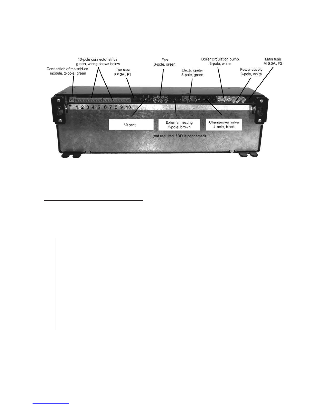
Figure 1: Back of type 614 control panel
Connection of the 2-pole add-on module:
1 (left) Tx +
2 (right) Tx -
Connection of the 10-pole connector strips:
1
2
3 1 - 5 vacant
4
5
6 boiler sensor (yellow)
7 buffer tank sensor, top (red )
8 buffer tank sensor, bottom (blue)
9 contact switch for loading door
10 exhaust gas sensor (silver)
A special feature of this control panel is that external modules (from BD model series) are automatically
recognised upon connection of the BUS interface. The external heating system is always to be connected
7

to the BD600 and not to the boiler control panel! The external heating is only connected to the type 614
control panel if no BD600 has been installed.
Please ensure that the securing screws in all of the connector plugs are properly tightened. Loose terminal
connections lead to contact resistances and therefore cause faulty switching. It is essential to ensure that
no cable has insulation interfering with its proper termination. Inspect the wiring connections once a year
and re-tighten the securing screws if required.
3 Indicators and controls
Figure 2: Front of type 614 control panel
The type 614 control panel has a touchscreen (touch-sensitive display screen). This means that all
settings are made directly using this screen. Other controls, like switches and dials are not necessary.
The unit switches on automatically when the mains power is connected.
Take care! The screen is touch sensitive; do not employ sharp instruments when using it! It is
sufficient to touch the screen lightly.
Navigating between menus Navigating to and setting of values
in the menus
Return to main menu / select module Moves one page back in menu
Return to standard screen Moves one page forward in menu
Start boiler Increases the value to be set
Swap between the standard screens Decreases the value to be set
8
Swap between the standard screens Confirms the value set
Moves one menu level higher Escapes data entry mode and
moves back in the menu
If the boiler is in smouldering mode, this is indicated by a loud audible alarm. The buzzer can be silenced for 5 min. by pressing the display. Please consult section 5.9 and in future prevent the smouldering
mode from occurring; it damages both the boiler and the environment.
4 The menu
4.1 Design
Once the unit is connected, the Künzel Logo appears for five seconds along with the designation of
the control unit at the lower edge of the screen (e.g. TS- 614, important information when addressing
questions to our customer support service).
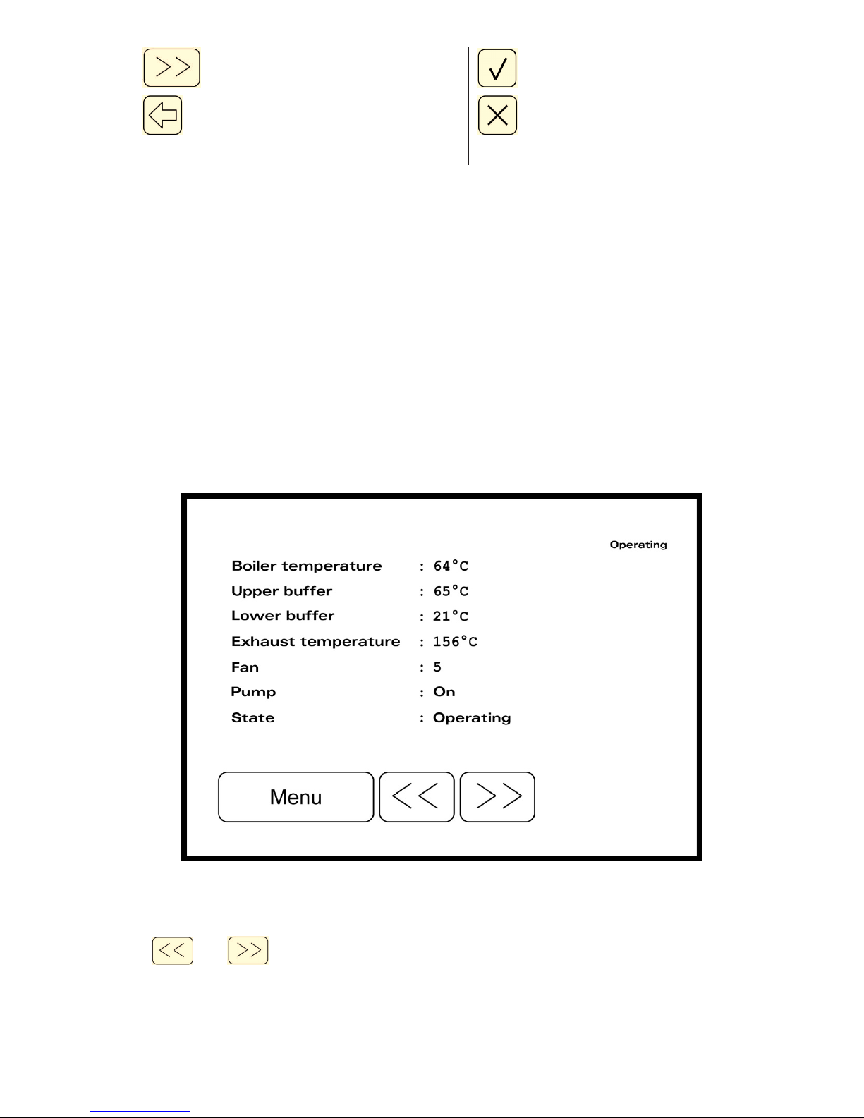
After this, the display changes to the standard screen:
Figure 3: The standard screen (here: boiler actual measurements)
The and button is used to switch to a boiler diagram, the boiler temperature display
and a rapid adjustment of the BD 600 heating controller (if connected). The boiler diagram shows the
9
 Loading...