

kunzel PK 10, PK 20, PK 15 Installation Manual
Installation manual
pellet boiler
PK 10, PK 15 and PK 20
May 4, 2009

Important!
This operating manual contains important information for the operator. The
boiler must be professionally installed and operated in order to avoid potential
accidents.
Familiarize yourself with the contents of this manual before installing and
operating the boiler.
Be sure to also comply with the regional regulatory provisions; they may differ
in full or in part from the requirements named in this manual. In this case, the
regulator requirements always have precedence! The master chimney sweep
responsible for your region can always provide information.
The company KÜNZEL would like to thank you for your trust!

Contents
1 Installation manual pellet boiler 4
1.1 Usage in compliance with statutory regulations . . . . . . . . . . . . . . . . . . . . . . 4
1.2 The key controls and components . . . . . . . . . . . . . . . . . . . . . . . . . . . . . 4
1.3 Installation . . . . . . . . . . . . . . . . . . . . . . . . . . . . . . . . . . . . . . . . . 5
1.3.1 The boiler room . . . . . . . . . . . . . . . . . . . . . . . . . . . . . . . . . . . 5
1.3.2 Transportation of boiler . . . . . . . . . . . . . . . . . . . . . . . . . . . . . . 6
1.4 Installation of the burner . . . . . . . . . . . . . . . . . . . . . . . . . . . . . . . . . . 6
1.5 Installation of the burner hood . . . . . . . . . . . . . . . . . . . . . . . . . . . . . . . 7
1.6 Operate cleaning lever (only PK 10 and PK 20) . . . . . . . . . . . . . . . . . . . . . . 8
1.7 Chimney connection . . . . . . . . . . . . . . . . . . . . . . . . . . . . . . . . . . . . 9
1.8 Heating connection . . . . . . . . . . . . . . . . . . . . . . . . . . . . . . . . . . . . . 9
1.8.1 General . . . . . . . . . . . . . . . . . . . . . . . . . . . . . . . . . . . . . . . 9
1.9 Electrical supply connection . . . . . . . . . . . . . . . . . . . . . . . . . . . . . . . . 10
1.9.1 General . . . . . . . . . . . . . . . . . . . . . . . . . . . . . . . . . . . . . . . 10
1.9.2 Boiler and burner . . . . . . . . . . . . . . . . . . . . . . . . . . . . . . . . . 11
1.9.3 Boiler sensors . . . . . . . . . . . . . . . . . . . . . . . . . . . . . . . . . . . . 11
2 Installation instructions for external pellet filling system 12
2.1 External conveyor screw . . . . . . . . . . . . . . . . . . . . . . . . . . . . . . . . . . 12
2.1.1 Rigid conveyor screw from the silo built by the building contractor . . . . . . . . 12
2.1.2 Flexible conveyor screw from pellet storage room . . . . . . . . . . . . . . . . . 15
2.1.3 Flexible conveyor screw from bag silo . . . . . . . . . . . . . . . . . . . . . . . 16
2.1.4 Storage tank with rigid conveyor screw . . . . . . . . . . . . . . . . . . . . . . 17
3 System proposals for the pellet boiler 18
3.1 PK2 system package - pellet boiler with domestic water heater and buffer tank . . . . . 18
3.2 PK3 system package - pellet boiler with combi-buffer tank . . . . . . . . . . . . . . . . 20
3.3 PK4 system package - pellet boiler with solar-suppl. heating and domestic hot water . . . 22
3.4 PK5 system package - pellet boiler with solar-supplemented heating . . . . . . . . . . . 23
3.5 Legend for the system packages . . . . . . . . . . . . . . . . . . . . . . . . . . . . . . 24
4 Technical data 25
4.1 Wiring diagrams . . . . . . . . . . . . . . . . . . . . . . . . . . . . . . . . . . . . . . 27
Cover image: Rigid conveyor screw from the silo built by the building contractor
3
1 Installation manual pellet boiler
1.1 Usage in compliance with statutory regulations
This pellet boileris approved for the operation of an open or closed circuit hot water heating system with
a permissible operating pressure of up to 3 bar and a maximum flow line temperature of 95◦C.
It is not permitted to operate the pellet boiler without a return flow booster. The operation of the return
flow booster is to be monitored. A 4-way mixing valve is sufficient as a return flow booster on systems
with a buffer tank.
The boilers supplied by KÜNZEL are stationary units that comply with the WEEE Directive. The electrical and electronic components contained in the boilers do not fall within the remit of this directive and
will therefore not be taken back by KÜNZEL. Please take these components to the recycling depot.
We do not assume any liability for any malfunctions resulting from the use of non-genuine KÜNZEL
components. This particularly applies to control units, external materials handling equipment and fuel
pipes from other manufacturers. We also do not assume any liability for operational difficulties resulting
from inadequate hydraulic and/or exhaust gas systems.
We reserve the right to make technical changes.
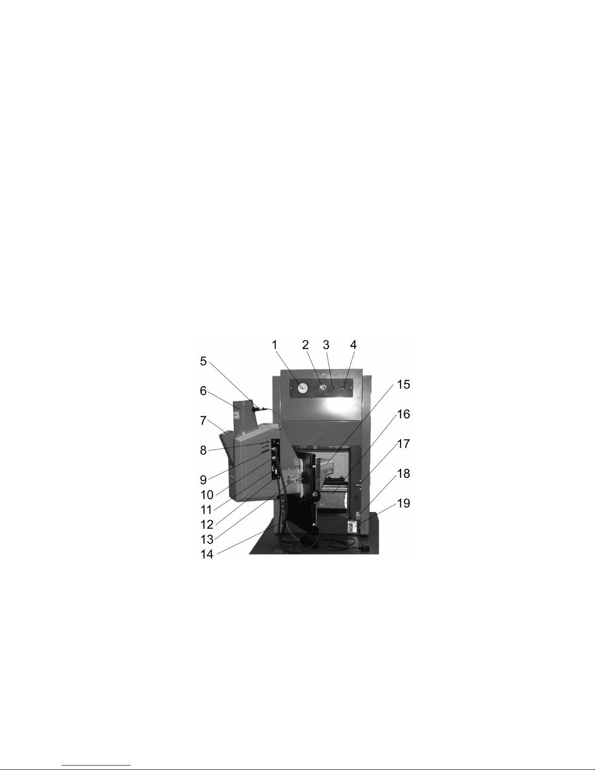
1.2 The key controls and components
1 Boiler thermometer 11 plugged connectors for boiler sensors, serial interface
2 boiler thermostats 12 Igniter safety device
3 Temperature safety limiter 13 Burner quick release lock
4 Mains power switch 14 Burner door
5 Fullness sensor 15 Flame deflector
6 Filling spout 16 Ash pan
Figure 1: The key controls and components
4

7 Burner control unit 17 Burner door catch
8 Main burner fuse 18 Door contact switch
9 Connection cable for conveyor screw 19 Type identification plate
10 Connection cable burner
1.3 Installation
• Before installing the pellet boiler approval must be obtained from the responsible master chimney
sweep.
• A flue gas system must be available that is approved for the operation of the pellet boiler.
• Please check whether planning permission is required.
• The boiler may only be installed by an approved heating specialist.
• When installing the boiler, ensure that all combustible or temperature-sensitive materials (cables,
insulation) are kept at least 40 cm away from the exhaust gas duct and 20 cm away from the boiler
shell.
• No combustible materials are permitted to be directly beside, above or in front of the boiler or the
filling hose. They must always be kept a minimum of 40 cm away.
• The boiler installation (heating system, electrical supply, safety equipment) must be state of the
art.
• If the heating system is operated with a flow line temperature of more than 100◦C , the boiler
plant must be reported to the responsible trade supervisory centre in accordance with the German
Ordinance on Steam Boilers.
• The relevant standards and building authority regulations must be complied with. Among other
regulations, the following apply: the German Fire Code (FeuVo), the Federal Immission Control
Ordinance (BImSchV.), the VDE guidelines, EN 303-5 and to the heating system DIN 4751.
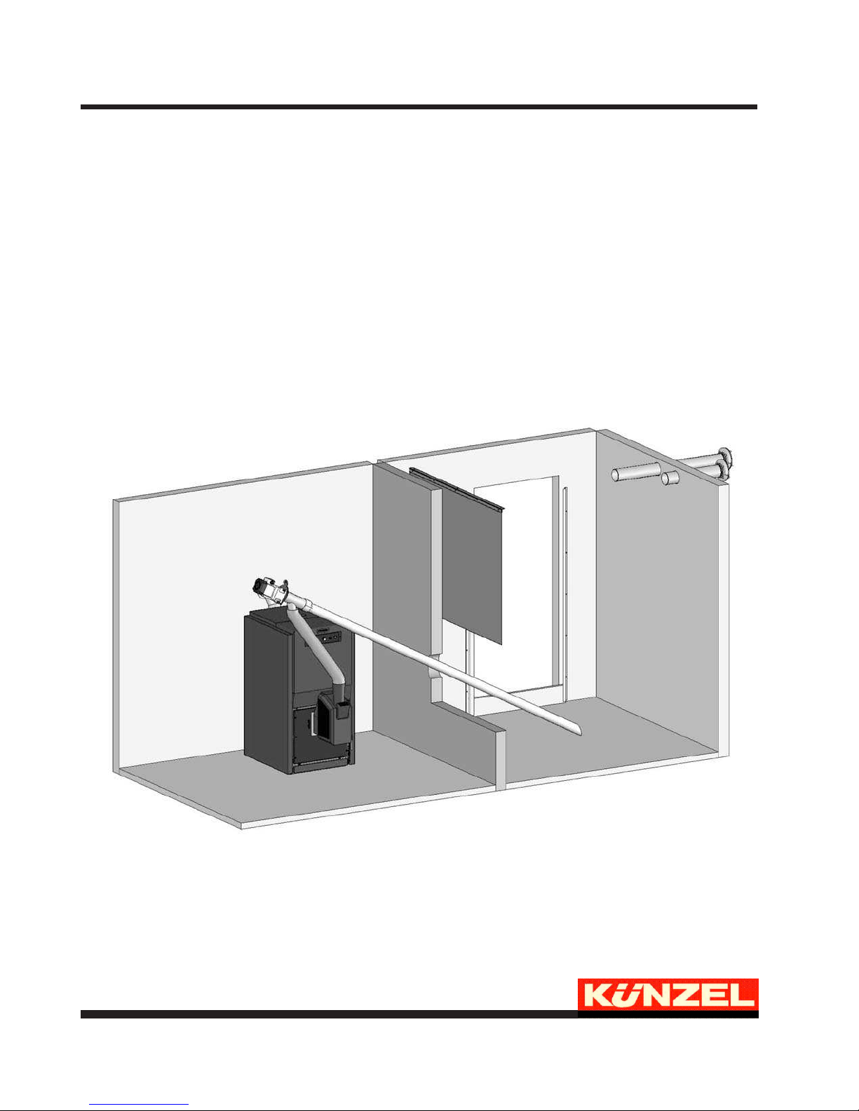
1.3.1 The boiler room
The pellet boiler may only be installed and the pellets stored in a dry,frost-proofroom that is approved for
the installation of boilers and the storage of fuels. The building contractor is to ensure that the installation
space is sufficiently ventilated.
A level, sufficiently strong floor manufactured from non-combustible material is adequate for the
installation of the pellet boiler. Should a foundation pedestal be used, this is to be made at least as
large as the dimensions of the boiler. The installation must also comply with the local regulations and
guidelines applicable to boiler room installations.
The boiler installation should already take account of the subsequent position of the materials handling
system!
5

Figure 2: Minimum offset dimensions for installation (view from above)
1.3.2 Transportation of boiler
As a result of its compact design, it is possible to bring the pellet boiler through a 750 mm door opening
into the installation space. In order to make the boiler casing easier to carry, carry bushings have been
fitted to the boiler, into which 1 inch pipe ends can be screwed.
• On the PK 15, these are located to the right and left below the covering caps.
• On the PK 10 and PK 20, the carry bushings are located at the front below the slanted cover panel
and beneath covering caps.
Once the installation has been completed, it should be ensured that the turbo gratings are correctly seated.
Illustrations on this subject can be found in the operating manual for the pellet boiler in the section
entitled "Maintenance and care" / "flue gas ducts".
1.4 Installation of the burner
Figure 3: Lock open Figure 4: Lock closed
The burner is secured in position using quick-release locks fitted to the burner door. When installing the
burner, proceed as follows:
6
• Remove the flame deflector from the burner shell. Important: The burner may only be installed or
removed without the deflector, otherwise the door insulation may be damaged.
• Now slide the burner into the burner hole in the burner door.
• Now set the two locks so that the burner is seated firmly in front of the burner door and the burner
contact switch is actuated. The burner is only permitted to have a very modest amount of play.
• As the burner seal beds in it is necessary to check the locks once again after about 4 weeks and
adjust them if required.
• Now re-install the flame deflector in the burner.
Only PK15:
At last the red hood has to be slid onto the burner fitting the rear metal sheet of the hood between washer
and clip (see pic. below).
Figure 5: Sliding on the hood
1.5 Installation of the burner hood
The pellet burner is supplied with the hood mounted. For maintenance or cleaning purposes, it can be
necessary to remove the hood. Before starting to do this, disconnect the burner completely from the
mains power supply. When removing the hood, proceed as follows:
• Remove the discharge chute cover. This requires the use of a T10 torx bit.
• Release the fastening screw holding the control module and lift it carefully upwards out of its
seating.
• Release the screwed fastenings holding the hood.
• Withdraw the hood rearwards
Use this procedure in reverse to install the hood. Only the torx screws provided may be used for the
installation of the hood. Please note: The burner may not be operated without a properly installed
hood. There is otherwise a risk of injury and the danger of electrical shocks !
7
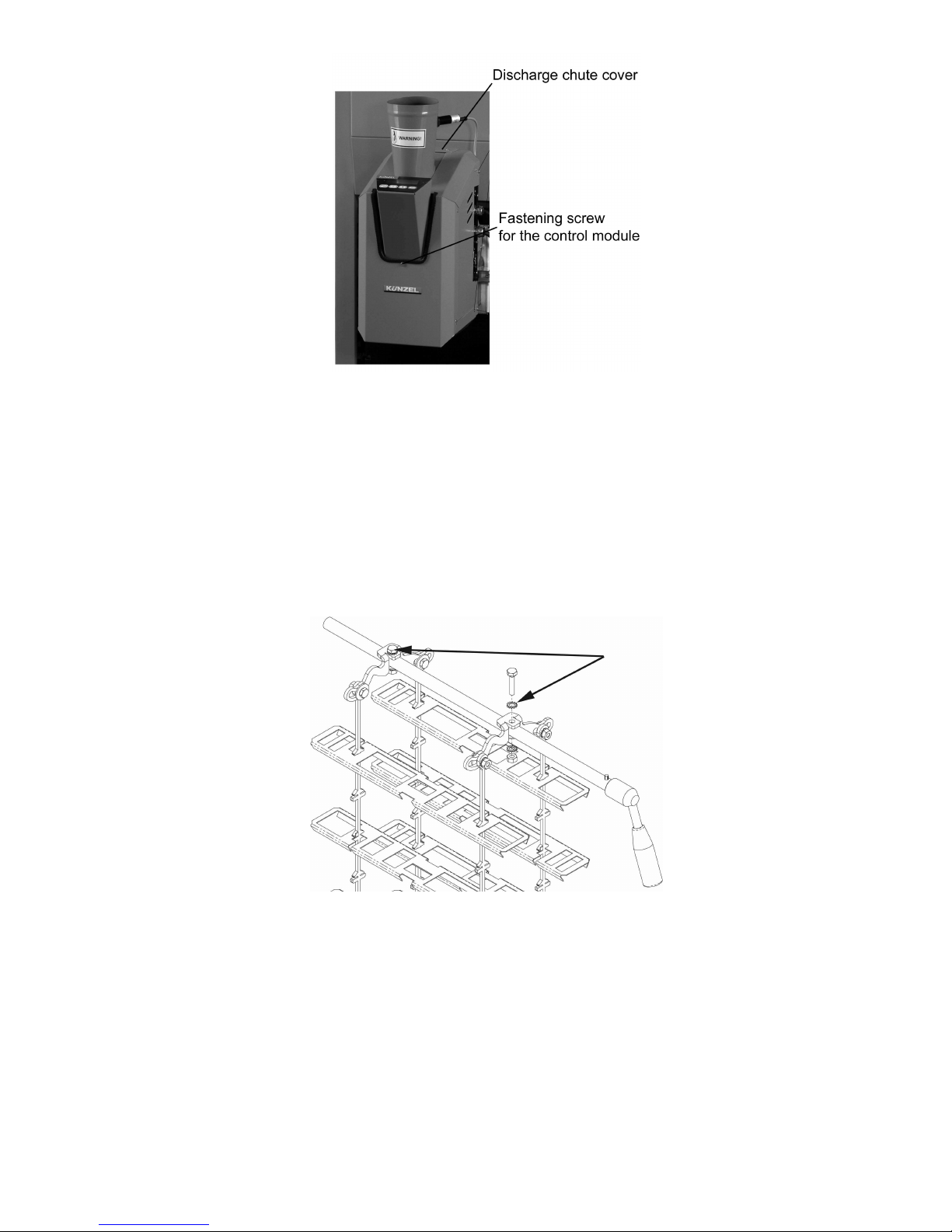
Figure 6: The burner hood
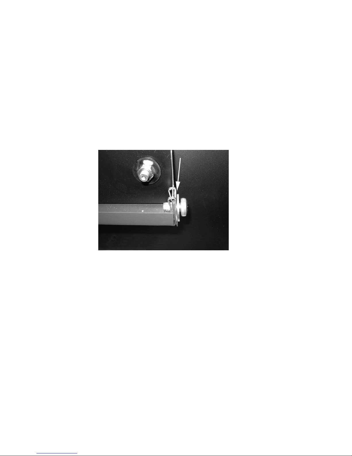
1.6 Operate cleaning lever (only PK 10 and PK 20)
As standard, the lever for the manual register cleaning mechanism is located on the right hand side of
the boiler (in the case of PK 15 on left hand side). Yet, sometimes it can be more sensible to move the
cleaning lever to the left hand side of the boiler, although it is only possible to do this on PK 10 and PK
20 boilers.
• Remove the red panel cover from the boiler and open the register cover located below it with an
Allen key.
• Release the screws marked with an arrow in the illustration and withdraw the shaft and handle
from the boiler in a rightward direction.
• Remove the black collar from the housing.
Figure 7: The cleaning lever
8

• Open the pre-cut hole on the left hand side of the boiler and re-insert the collar in this hole.
• Now slide the shaft from the left into the boiler; ensure it is positioned correctly (underneath the
follower lever, see figure!)
• Bolt the shaft and the follower lever back together.
1.7 Chimney connection
The KÜNZEL pellet boiler is fitted with a forced draft fan. In order to ensure safe operation of the pellet
boiler, it is necessary to ensure that the flue gas branch of the pellet boiler has a negative pressure of at
least 10 Pa under all operating conditions. However, this negative pressure may not exceed 18 Pa under
any operating conditions. KÜNZEL recommends the use of a draft regulating device. When putting the
unit into service for the first time, the draft is to be measured and recorded when the unit is cold and
when it is operating at its maximum output setting.
The exhaust gas duct to the chimney should be as short as possible, without any bends and installed at
a slight incline. The connection to the chimney should have an aerodynamic design that curves upward.
The connector joining the furnace and the chimney must comply with EN 1856-2:2004 and have the
required identification marking (CE). In accordance with EN 1856-2:2004, non-insulated connectors
must be kept at least 40cm cm away from combustible components. We recommend the use of insulated
connectors.
The figures required for the chimney design calculations can be found in the technical data listed in
section 4 on page 25. Calculated chimney diameters that are smaller than the flue gas branch of the boiler
are not permissible.
Important: Please note that the low exhaust temperatures occurring during prolonged operation may
mean that it is necessary to fit a moisture-resistant chimney (thermal conductivity factor - resistance
group I in accordance with DIN 18160/T1).
Before connecting the pellet boiler to an existing chimney, subject it to a chimney calculation or obtain
a chimney report. Before commencing with the installation it is essential to obtain the approval of your
local master chimney sweep.
It is essential to ensure that the flue gas duct is airtight. Exhaust gases could otherwise leak into the boiler
room under some circumstances. This applies in particular to the cleaning hatches on the duct elbows.
1.8 Heating connection
1.8.1 General
The PK type pellet boiler are designed for use with open or closed-circuit heating systems with a maximum operating pressure of 3 bar and a maximum flow line temperature of 95◦C.
The following safety equipment is to be installed by the building contractor:
• A pressurised expansion tank (please take account of any buffer tanks fitted to the system)
• A safety valvewitha maximum actuation pressure of 3 bar at the highest point of the heat generator
• A thermometer and a manometer
9
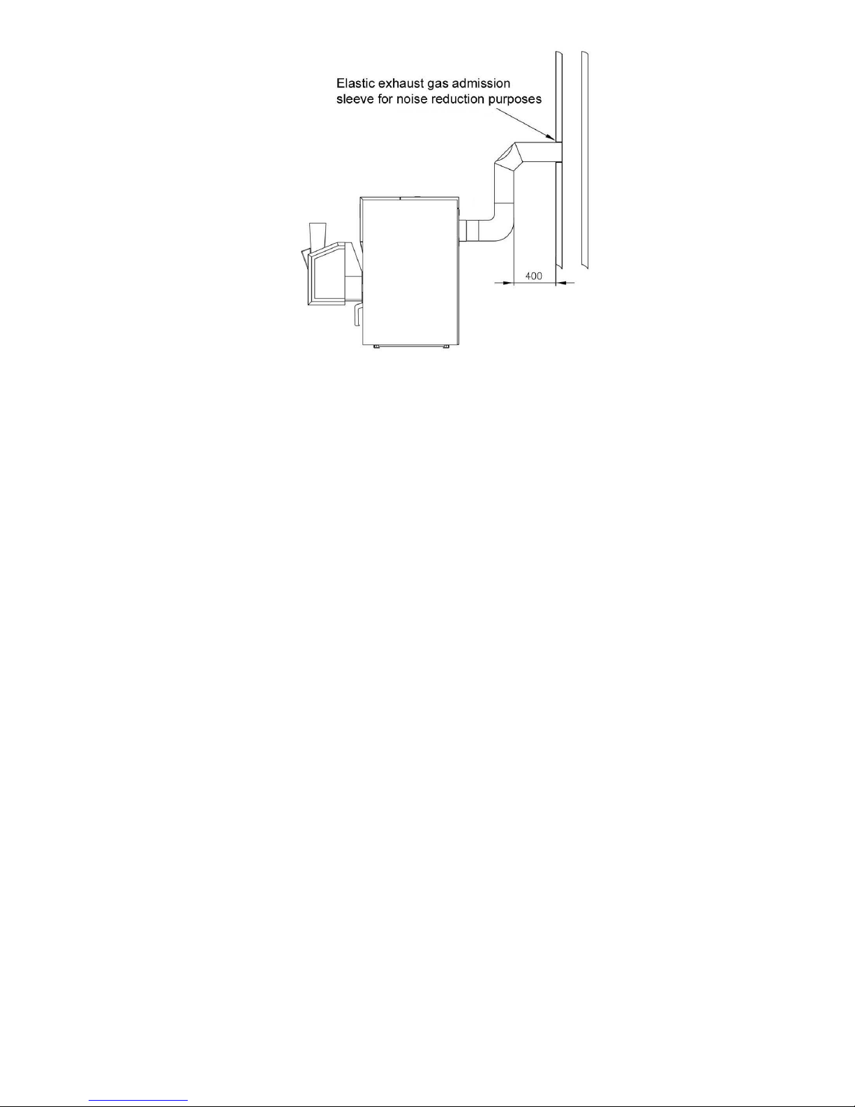
Figure 8: The chimney connection
Please note: Only products whose components have been tested may be employed
We recommend designing the heating system in line with the example system detailed in section 3 on
page 25. KÜNZEL absolutely recommends the use of a buffer tank with a capacity of at least 500 l.
. Using a buffer tank ensures that the boiler can operate with extended burner operation times even
when the heat consumption of the heating system is either low or fluctuating markedly. This leads to
a significant reduction in emissions, as well as wear and tear and soiling of the burner and igniter element.
In order to prevent the pellet boiler from corroding, the boiler is operated with an elevated minimum
temperature. This is 50◦C for systems without a buffer tank, and 60◦C for systems with a buffer tank.
For this reason, a separate return flow temperature booster has to be fitted, e.g., the Thermomix valve
(Part. No. 150218) from KÜNZEL.
Due to the elevated minimum temperatures, the heating system must always be equipped with an automatic mixing valve. 3-way mixing valves are to be fitted to systems with buffer tanks. 4 way mixing
valves are to be fitted to systems without a buffer tank.
1.9 Electrical supply connection
1.9.1 General
• The electrical supply must be connected by an approved electrician.
• A residual current circuit breaker is to be fitted.
• The electrical supply connection for the boiler is to be protected by a max. 10 A fuse.
10
 Loading...