

kunzel BT 2030, BT 2050 Operating Manual
Operating manual
Wood gasifier boiler
BT 2030 and BT 2050

June 22, 2010
2

Important!
This operating manual contains important information for the operator. The
boiler must be professionally installed and operated in order to avoid potential
accidents.
Familiarize yourself with the contents of this manual before installing and
operating the boiler.
Be sure to also comply with the regional regulatory provisions; they may differ
in full or in part from the requirements named in this manual. In this case, the
regulator requirements always have precedence! The master chimney sweep
responsible for your region can always provide information.
The company KÜNZEL would like to thank you for your trust!

Contents
1 Safety instructions 5
1.1 Intended use . . . . . . . . . . . . . . . . . . . . . . . . . . . . . . . . . . . . . . . . . 5
1.2 General safety instructions . . . . . . . . . . . . . . . . . . . . . . . . . . . . . . . . . 5
2 Installation 6
2.1 General . . . . . . . . . . . . . . . . . . . . . . . . . . . . . . . . . . . . . . . . . . . 6
2.2 Delivery . . . . . . . . . . . . . . . . . . . . . . . . . . . . . . . . . . . . . . . . . . . 7
2.3 Chimney connection . . . . . . . . . . . . . . . . . . . . . . . . . . . . . . . . . . . . 7
2.4 Connection to the heating system . . . . . . . . . . . . . . . . . . . . . . . . . . . . . . 8
2.5 Electrical connections . . . . . . . . . . . . . . . . . . . . . . . . . . . . . . . . . . . . 8
2.6 Exhaust gas measurements . . . . . . . . . . . . . . . . . . . . . . . . . . . . . . . . . 9
3 The KÜNZEL Wood gasifier boiler BT 10
3.1 Nameplate . . . . . . . . . . . . . . . . . . . . . . . . . . . . . . . . . . . . . . . . . . 10
3.2 Design of boiler . . . . . . . . . . . . . . . . . . . . . . . . . . . . . . . . . . . . . . . 11
3.3 Design of turbo-burner . . . . . . . . . . . . . . . . . . . . . . . . . . . . . . . . . . . 12
3.4 The feeder hatch lock . . . . . . . . . . . . . . . . . . . . . . . . . . . . . . . . . . . . 12
3.5 Control panel . . . . . . . . . . . . . . . . . . . . . . . . . . . . . . . . . . . . . . . . 13
4 Heating 13
4.1 Heating with wood . . . . . . . . . . . . . . . . . . . . . . . . . . . . . . . . . . . . . 13
4.2 Initial startup . . . . . . . . . . . . . . . . . . . . . . . . . . . . . . . . . . . . . . . . 15
4.3 Warming-up and adding fuel . . . . . . . . . . . . . . . . . . . . . . . . . . . . . . . . 15
5 Maintenance and servicing 18
5.1 Daily cleaning . . . . . . . . . . . . . . . . . . . . . . . . . . . . . . . . . . . . . . . . 18
5.2 Monthly cleaning . . . . . . . . . . . . . . . . . . . . . . . . . . . . . . . . . . . . . . 18
5.3 Quarterly cleaning . . . . . . . . . . . . . . . . . . . . . . . . . . . . . . . . . . . . . 20
5.3.1 Smoke ducts . . . . . . . . . . . . . . . . . . . . . . . . . . . . . . . . . . . . 20
5.3.2 Fans . . . . . . . . . . . . . . . . . . . . . . . . . . . . . . . . . . . . . . . . . 20
6 What to do in the case of a malfunction 21
7 Technical Data 24

1 Safety instructions
1.1 Intended use
All corresponding norms and regulations stipulated by the building authorities should be observed.
This boiler isapprovedfor use in open and closed warm-water heating systemswith a permitted operating
pressure of max. 3 bar and a maximum flow temperature of 95.C.
The boiler may not be operated without return flow increase. The return flow increase function should be
monitored.
The operator must ensure that the wood gasification boiler can always burn the introduced fuel with the
fan running by installing an adequately-sized buffer tank (at least 55 litres per kilowatt boiler capacity)
or an equally effective technical arrangement, and by fitting a fuel feed mechanism that adjusts the
amount of fuel introduced to the boiler to the amount of energy required. Smouldering combustion is
only permitted to take place for short periods of time, and under no circumstances may this method of
combustion be used to regulate the boiler output.
This Wood Combustion Water Boiler may only be fired with dry, small-cut and natural wood. Do not use
wood shavings or dust.
–Danger of explosion–
Under no circumstances should wood be burned which has been treated with preservatives. This should
be brought to special disposal units.
We reserve the right to make technical changes.
We are not liable for functional problems resulting from the use of components other than original
KÜNZEL components. This applies in particular to controllers and external conveyor equipment from
other manufacturers. We also do not accept liability for operating problems resulting from insufficient
hydraulics- and/or exhaust systems.
1.2 General safety instructions
1. Read all of the accompanying instructions carefully before commissioning the unit.
2. The installation of the boiler (heating system, electrical supply, safety equipment) must be state of
the art. The installation must comply with the relevant standards and building codes.
3. Check the operation of the safety valveand the thermal discharge safety device at least once a year.
4. The electrical supply must be connected by a qualified electrician.
5. The boiler installation should ensure that combustible or temperature-sensitive materials (cables,
insulation) are kept at least 40 cm away from the draught regulator and the boiler flue duct.
6. Open the furnace chamber door slowly and only until the safety retention catch has engaged. Now
wait about 10 seconds. Then lift the retention catch and open the door completely.
7. Never leave the boiler unattended with the furnace chamber door, ash hatch or warm-up damper
open.
8. Avoid opening the ash hatch while the boiler is in operation because sparks can escape from the
unit.
5

9. Do not store any combustible materials directly beside or in front of the boiler.
10. What to do after a power supply failure: The wood gasification boiler does not automatically
switch itself back on after a power supply failure. When switching it back on proceed as follows:
(a) Once mains power has been restored, wait a while until it is certain that the electrical power
supply is functioning reliably again.
(b) Open the furnace chamber door as described and ensure that a sufficient level of embers is
present in the furnace chamber.
(c) If the embers have been completely extinguished, the furnace chamber must be cleaned be-
fore the boiler is restarted. When doing so, follow the described procedure.
(d) If the furnace chamber does contain embers, do not introduce any additional fuel.
(e) Close the furnace chamber door and start the control panel.
(f) Following the start, it is imperative to keep the furnace chamber door and the ash hatch
closed for at least half an hour. During this time, the progressive smouldering of the
fuel during the power supply failure can lead to very high concentrations of carbon
monoxide in the exhaust gases. Under some circumstances, there is a risk of explosion!
(g) During this period, the boiler can continue to be operated normally.
2 Installation
2.1 General
• The KÜNZEL-Wood Combustion Water Boiler is design tested (DIN K 2106/90) and complies
with the German BImSchV regulations dated October 1988.
• Before installing the wood gasification boiler, it must be ensured that all of the statutory requirements have been met and that a permit for the installation and operation of the unit has been
granted.
• The wood gasification boiler may only be operated in combination with a buffer tank with a capacity of at least 55 litres per kilowatt boiler capacity.
• Please enquire before installation whether building permission is necessary.
• The installation of the boiler should only by carried out by an authorised heating technician.
• The boiler should be installed in a separate room that is used exclusively for heating purposes.
This room must meet the requirements laid down by the German Fire Code for boiler rooms with
a rated output of less than 50 kilowatts. We strongly advise against installing the boiler in dwelling
rooms.
• Carry bushings are provided on the boiler for its transportation to the installation site. They are
located in the plenum chamber and on the back of the boiler. It is imperative that the plugs for
sealing the carry bushings are replaced after use!
6
2.2 Delivery
The Wood Combustion Water Boiler is supplied with:
• 1 Guarantee card
• 1 Rake, 1 Cleaning brush
2.3 Chimney connection
The KÜNZEL-Wood Combustion Water Boiler is equipped with a draught regulator, so that it does not
necessarily need to be installed immediately next to a chimney. The draught regulator should be set so
that the effective draught lies between 10Pa and 18Pa. Should the draught in the chimney be very strong,
it may be necessary to install a second draught controller to ensure that the limit of 18Pa is not exceeded.
In such a case, this controller should be made available in the building concerned. If the back smoke duct
is used for exhaust gasextraction, a further controller can also be installed on the unused side smokeduct.
The draught regulator and the smoke duct sections are removable to enable connection to the chimney on
any of the three sides. However, the draught regulator can only be mounted on the two side duct sections.
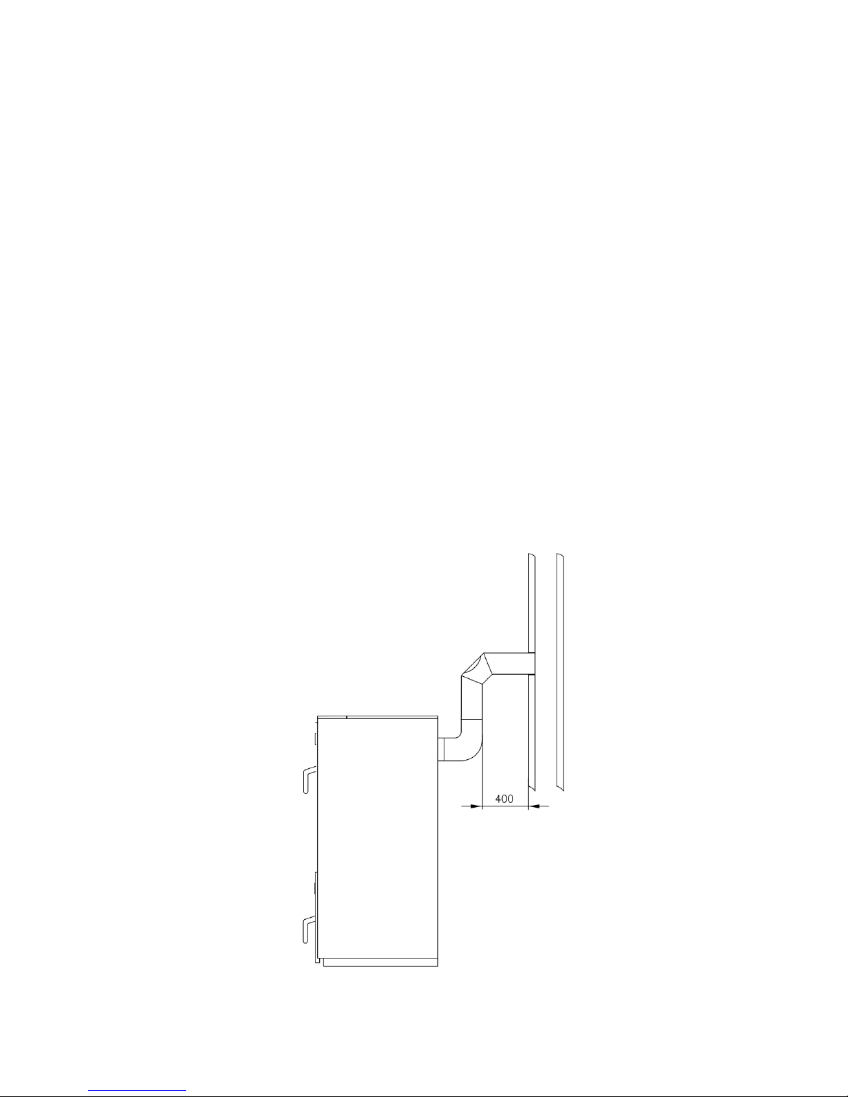
The exhaust pipe should be short, if possible without any further bends and attached at an ascending
angle. It should join the chimney in a position favourable to the draught current and be rounded off at
the top. The DIN 4705 norm applicable. For the chimney calculations please refer to the Technical Data.
Please note that the chimney should be not only be calculated for the rated load but also for re-feeding.
Calculated chimney diameters which are smaller than the smoke ducts of the boiler are not permissible.
Figure 1: Distance to wall
7
2.4 Connection to the heating system
In order to prevent break-downs in operation, we recommend to connect the boiler to the heating system
by following a system diagram provided by KÜNZEL. You can download these diagrams from our
(german) homepage www.kuenzel.de (Service->Informationsmaterial->Planungsmappe HV,FO).
The regulation still applies that closed-circuit heating systems must be equipped with a componenttested thermic outlet control with a temperature setting of 95o C (e.g. Art. No. 150312 by KÜNZEL).
The thermic outlet control must installed in the coldwater pipe leading to the safety heat exchanger. It is
important to make sure that the water pressure is maintained at a constant minimum of 2bar. The inlet
and outlet pipes should not have any shut-off valves. The pipe cross-section should be NW 20.
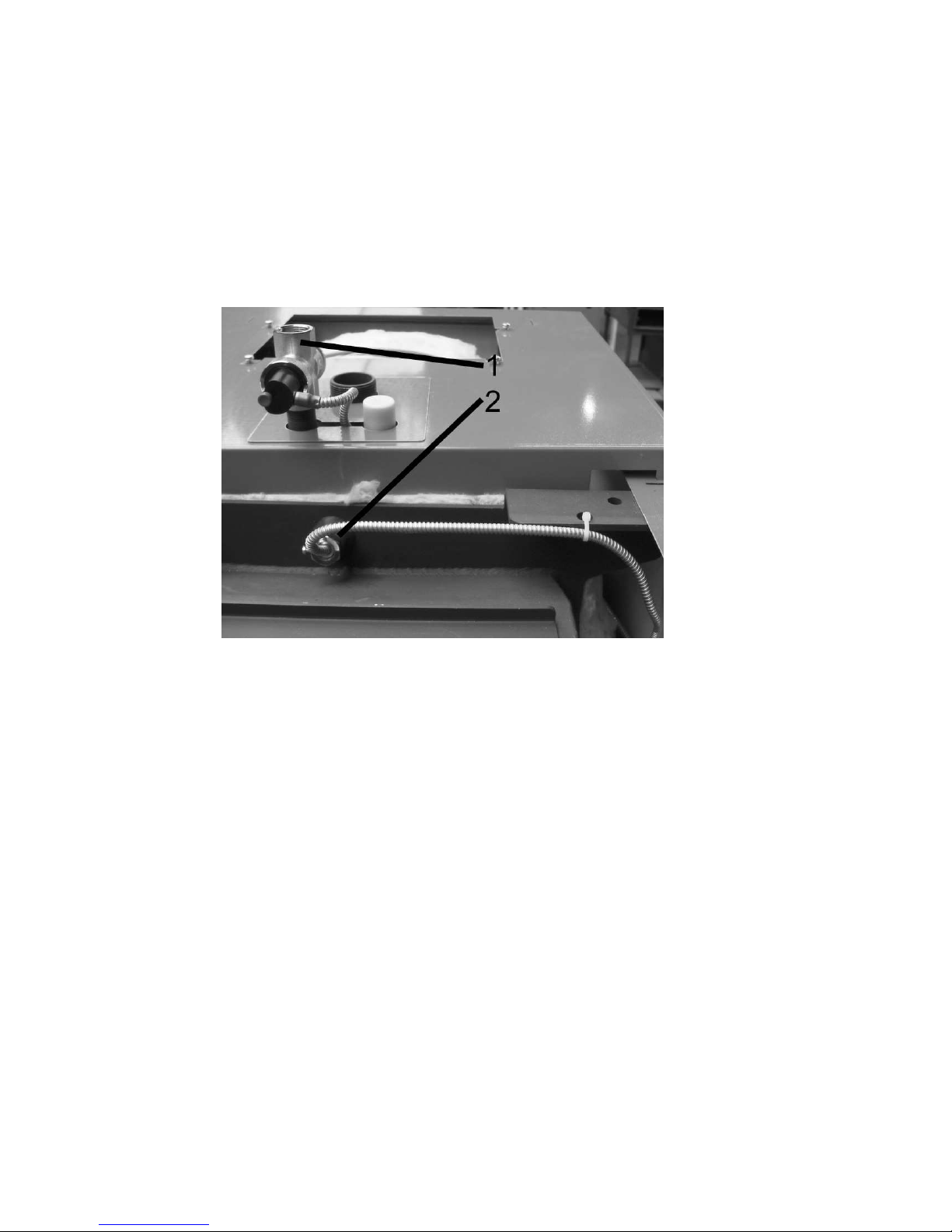
Figure 2: Thermal discharge safety device, installation in the boiler
The valve for the thermal discharge safety device [1] is installed on the connections. The sensor pipe is
then fed beneath the boiler jacket to the left side of the boiler. Here, it is routed below the mount for the
side panel towards the rear of the unit and fixed in place using cable ties, as shown in the illustration.
The immersion sleeve (max. 150 mm) is screwed into the coupling [2].
2.5 Electrical connections
The electrical connections must be installed by an authorised electrician. A FI-switch should be installed.
The electrical supply must meet the following specifications:
specifications
Voltage rating 240 Volt
Current rating 10 Ampere
Frequency rating 50 Herz
Within the boiler only heat resistant silicone wiring should be used! Do not use any PVC wiring.
The wiring is not permitted to be in contact with the flue gas header!
8

There is a cable duct on the left and right hand side of the boiler, through which the cables are routed
to the rear of the boiler. The left hand cable duct, in which the cables for the lambda sensor, the exhaust
sensors, etc., are located, is only to be used for sensor cables. The current-carrying cables are to be routed
in the right hand cable duct.
The control panel is pre-installed.
2.6 Exhaust gas measurements
When taking exhaust gas measurements, please note the following:
1. The wood gasification boiler should have been in operation for at least a week so that the gases
accumulated within components and door seals as a result of the manufacturing process have a
chance to escape.
2. The boiler must be thoroughly cleaned before the measurement procedure takes place. Please read
the operating instructions in order to learn how this should be done.
It is particularly important to ensure that the inlet air ducts are not blocked. Do not just remove the
flue ash from beneath and behind the combustion chamber shell. Remove it also from the flue gas
header and the flue gas pipe. The fan sealing damper must be free to move.
3. Use only untreated and dry wood (max. 20Short and irregularly shaped logs also burn in a nonuniform manner and cause cavities to develop within the firebed. This leads to a deterioration in
the performance and emissions values.
4. Ensure the boiler is up to operating temperature before commencing with the measurement procedure. This means that the boiler temperature must be at least 75◦C and the exhaust gas temperature
must have reached at least 150◦C.
5. Heat the boiler for about an hour before starting to take measurements. The furnace chamber
should only be half filled for this. Lay the logs lengthwise and close together. Now fire the boiler
until the measurement procedure commences.
6. During the warm-up phase and the measurement, it must be ensured that the heat consumption
is adequate. The buffer tank must be empty before the measurement procedure commences. If
necessary, turn all of the radiator valves completely open and switch on the storage heater. Set the
boiler thermostat to 90◦C.
7. The boiler fan is not permitted to switch off during the measurement procedure. Type BT20xx
boilers have to be run at the maximum exhaust gas temperature.
8. During the measurement procedure, it is imperative to deactivate the fan speed reduction feature
using the control panels 214, 414 and 614! Please read the respective control panel operating
instructions in order to learn how to do this.
9. Distribute the embers evenly within the boiler before starting to take any measurements. The height
of the firebed should still be about 10 cm. Then lay the 0.5 m long logs lengthwise and close
together upon this firebed. The measurement procedure can commence five minutes after placing
the wood upon the firebed.
9
 Loading...