

Page 1
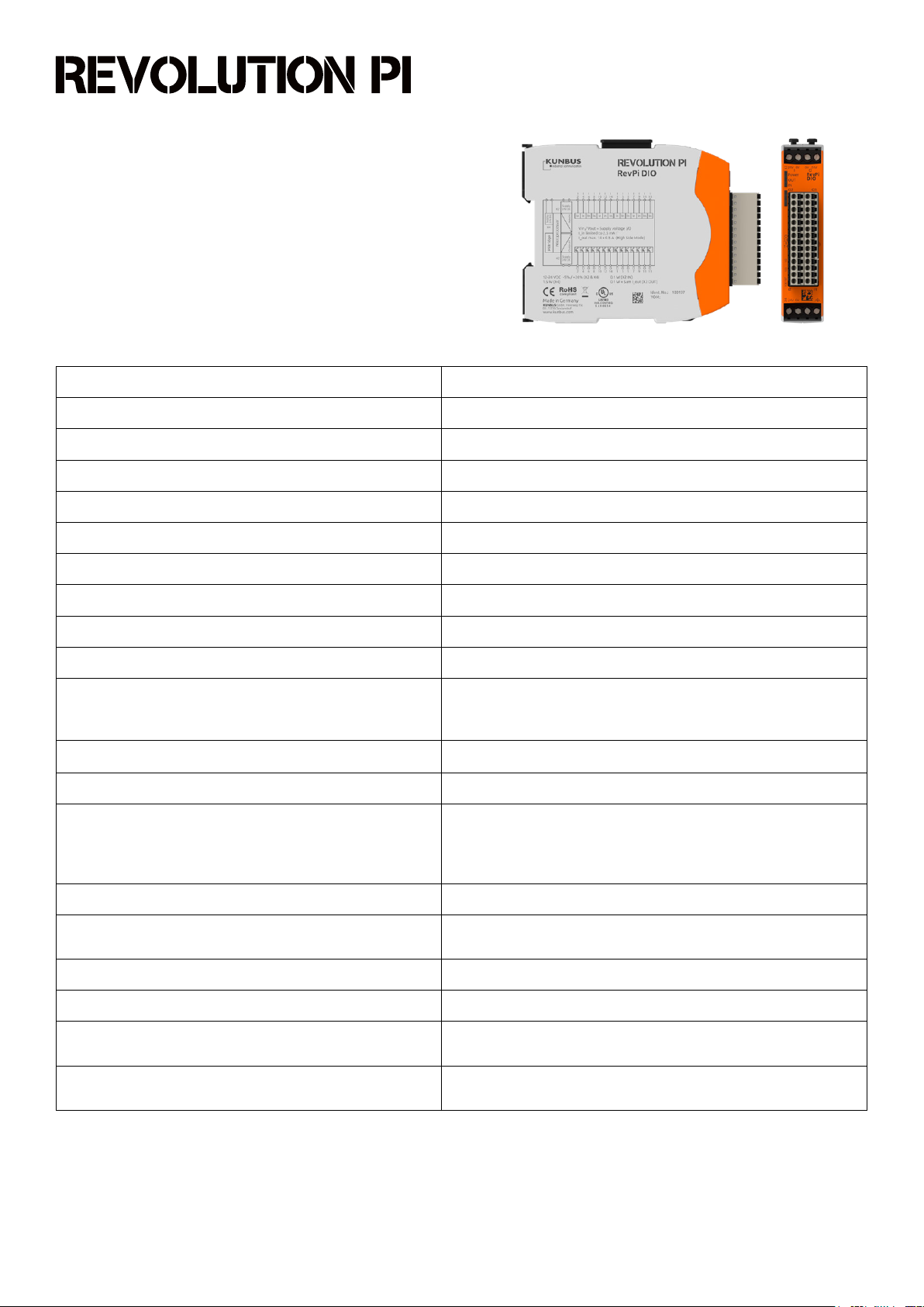
RevPi DIO
Article No.: 100197
Technical Data
Housing dimensions (H x W x D) 96 x 22.5 x 110.5 mm
Housing type DIN rail housing (for DIN rail version EN 50022)
Housing material Polycarbonate
Weight approx. 100 g / 130 g (incl. connectors)
IP Code IP20
Power supply 12-24 V DC -5 % / +20 % (X2 and X4)
1
Max. power consumption 1.5 Watt (X4/power supply)
Operating temperature -40 °C....+55 °C
Storage temperature -40 °C....+85 °C
Humidity (at 40 °C) 93 % (non-condensing)
2 x 4-pole screw-type terminal for power supply
Connectors
2 x 14-pin socket connectors with spring clamp contacts (0.2 - 1.5
mm²) for IOs, pitch 3.5 mm (Wieland Item No. 27.630.4453.0)
Optical indicator 3 status LEDs (bi-color)
Number of digital input channels 14
Galvanically isolated from the system bus and from the outputs,
Input type
individually congurable as direct digital input, counter rising
edge, counter falling edge or together with neighboured input as
encoder
2
Input current limitation 2.4 mA (at 24 V power supply)
Input thresholds
At 24 V compatible according to EN 61131-2 to Type I and III
sensors
Digital debounce circuit Collectively adjustable for all inputs: o, 25 µs, 750 µs or 3 ms
Maximum frequency resolution of the counter inputs 2 kHz (corresponding to 500 Hz encoder sequence)
Alarm
Input protection
1
Three independent supply voltage sources must be available for galvanic isolation of the inputs and outputs.
2
For each DIO module, a maximum of 6 inputs can be dened as 6 counters or 12 inputs as 6 decoders. Counters and decoders are stored as 32-bit integers in the
process image. Reset of counters/encoders via ioctl calls from the kernel driver piControl.
KUNBUS GmbH, Heerweg 15C, 73770 Denkendorf, Germany | Tel: +49 (0) 711 400 91 500 | Fax: +49 (0) 711 400 91 501 | Email: info@kunbus.com | Web: www.kunbus.com
For auxiliary voltages below 19 V and below 9 V,
overtemperature
According to EN 61131-2 (IEC 61000-4-4, -5, -6, and -2) against
burst, RF injection, external voltages from -3 V to +36 V
Version: EN 1.6
page 1/2Errors excepted and possible alterations without prior notice.
Page 2
RevPi DIO
Article No.: 100197
Technical Data
Number of digital output channels 14
Galvanically isolated from the system bus and the inputs,
Output type
Maximum current per output 500 mA (high-side mode), 100 mA (push-pull mode)
individually congurable as direct digital output with high-side
or push-pull drivers as well as a PWM output
3
PWM frequency
Alarm
Collectively selectable for all outputs: 40 Hz, 80 Hz, 160 Hz,
200 Hz, 400 Hz
3
Thermal shutdown or short circuit of outputs (individually for each
output)
In the event of communication failure with the controller (after
Dual watchdog function
Output protection
Compatible modules for system expansion
50 ms or 500 ms 4) or internal communication with the CPU (after
9 ms, hardware-controlled), the outputs are reseted to zero
According to EN 61131-2 (IEC 61000-4-4, -5, -6, and -2) against short
circuit, overload, burst, ESD
All RevPi base module, expansion modules and RevPi Gate
modules (connected via overhead PiBridge connector)
Protection of the power supply inputs Reverse polarity protected, transient overvoltages
EMC interference emission according to EN 61000-6-4
EMC immunity according to EN 61000-6-2
RoHS conformity Yes
CE conformity Yes
UL certication Yes, UL-File-No. E494534
3
The PWM pulse width is stored as a value from 0 to 100 in the process image in 1 byte. The maximum resolution of the conversion of this value in % by the module depends on the PWM
frequency: 40 Hz / 1%, 80 Hz / 2%, 160 Hz / 4%, 200 Hz / 5%, 400 Hz / 10%.
4
50 ms for all RevPi DIO with software version 1.4 or older.
500 ms for all RevPi DIO with software version 1.5 or younger.
KUNBUS GmbH, Heerweg 15C, 73770 Denkendorf, Germany | Tel: +49 (0) 711 400 91 500 | Fax: +49 (0) 711 400 91 501 | Email: info@kunbus.com | Web: www.kunbus.com
page 2/2Errors excepted and possible alterations without prior notice.
Version: EN 1.6
 Loading...