

Kuma Stoves Wood Classic Installation And Operating Instructions Manual

Kuma Stoves
Hayden, ID. USA
MODEL:
WOOD CLASSIC
Wood Stove
INSTALLATION AND OPERATING
INSTRUCTIONS
*SAVE THESE INSTRUCTIONS*
This manual describes the installation and operation of
the KUMA model Wood Classic wood stove. Under specific
test conditions, this heater has been shown to meet the U.S.
Environmental Protection Agency’s emission limits for
residential wood stoves.

Please read the following safety precautions and the entire
installation and operating instructions.
SAFETY PRECAUTIONS
1. If this stove is not properly installed, a house fire can occur. For your protection, follow the installation
instructions provided. We recommend contacting local building or fire officials regarding restrictions and
installation inspection requirements in your area. We also recommend that your Kuma model Wood Classic wood
stove be installed by a properly trained and licensed installer, preferably and NFI (National Fireplace Institute)
expert.
2. DO NOT CONNECT THIS UNIT TO A CHIMNEY FLUE SERVING ANOTHER APPLIANCE.
3. Do not use gasoline, gasoline-type lantern fuel, kerosene, charcoal lighter fluid, or similar liquids to start or
“freshen up” a fire in this heater. Keep all such liquids well away from the heater while it is in use.
4. Do not burn garbage.
5. Do not overfire. The stove is in an overfire position if any part of the stove glows. If this should happen,
immediately close air damper.
6. WARNING: DO NOT INSTALL IN A SLEEPING ROOM.
7. Caution: The structural integrity of a mobile home floor, wall, and ceiling/roof must be maintained.
8. Do not use single-wall pipe for exterior chimney or mobile home applications.
9. When installing into an existing metal or masonry chimney, examine the chimney system carefully. If you have
any questions, seek professional advice. DO NOT CONNECT THIS UNIT TO A CHIMNEY FLUE
SERVING ANOTHER APPLIANCE.
10. Note all minimum clearances to combustibles. Installation must comply with minimum clearances as listed in
this manual.
11. INSTALL AND USE IN ACCORDANCE WITH THE MANUFACTURER’S INSTALLATION AND
OPERATING INSTRUCTIONS ONLY.
12. Safety Notice: If this heater is not properly installed, a house fire may result. For your safety, follow the
installation directions.
13. Do not operate stove with firing door in an open position.
14. This room heater must be connected to a minimum 6” diameter listed chimney that complies with U.L. 103,
HT-Type factory built chimney, or a code approved masonry chimney with a U.L. 1777 listed flue liner.
15. When connecting single-wall stove or double-wall listed chimney connector from the stove flue collar to the
listed factory built chimney or masonry chimney, make sure all interconnecting joints of the flue pipe and the
connection at the flue collar are secured with three (3) sheet metal screws.
16. When connecting this stove to a masonry chimney, make sure you observe all applicable clearances to
combustible ceilings, walls, or other combustibles. A masonry chimney must be a 6” diameter minimum and
constructed with a liner according to NFPA 211 code. If you are passing a chimney through a combustible wall to
an outside chimney, use a U.L. 103, HT-Type approved insulated chimney section with a wall thimble,
maintaining chimney to manufacturer’s listed minimum clearance to combustibles. When attempting to connect
this stove into a masonry chimney use these steps:
a. Chip out hole through masonry into liner at least 6” in diameter.
b. Install stainless steel single-wall liner all the way into the masonry liner (see figure 2A).
c. Seal or mortar stainless liner in with a refractory high-test type cement.
d. Connect stove pipe into masonry hole.
e. When passing through a combustible wall into masonry chimney, cut hole in wall large enough for
the wall thimble, and use a U.L. 103, HT-Type insulated chimney section that directly connects into
masonry liner described above (refer to figure 2A).
CODES AND APPROVALS:
The Kuma model Wood Classic wood stove is tested to U.L. 1482 safety standard and is
listed by Omni Test Laboratories, Inc. This unit is also approved for alcove installations.
Maximum alcove depth: 48”. Minimum clearance from stove top to ceiling: 52”.

MOBILE HOME INSTALLATION INSTRUCTIONS
Model: Wood Classic
CAUTION: THE STRUCTURAL INTEGRITY OF A MOBILE HOME FLOOR, WALL, AND CEILING/ROOF
MUST BE MAINTAINED.
CAUTION: DO NOT INSTALL IN A SLEEPING ROOM.
Before you start, ensure that there are no major obstructions (i.e. floor joists, ceiling joists, electrical
wires, heat ducts, plumbing, etc.).
Clearance: backwall– 6”, corners– 4”, sidewall– 14” (using HT-Type listed chimney and double-wall
connector). See figures 5 and 6. Consult your local building official and build your hearth pad to local building
requirements.
Typical hearth pad (see example: typical hearth pad on page 3)- 16” to front of unit, 6” to sides (hearth top
must be non-combustible).
Material required for installation: 4” outside air duct with screen, caulking to seal roof flashing,
assorted nails and screws, 8-gauge ground wire, 3/8 lag bolts to fasten stove to the floor (length will depend upon
hearth thickness)
Tools required: saber saw, screwdrivers, measuring tape, pencil, plumb line, electric drill and assorted
bits, tin shears, knife, pliers, hammer.
1. After locating possible obstructions (joists, pipes, etc.) and taking into account the necessary combustible clearances (fig.2),
position the stove in the intended installation position. Use a plumb line to locate the position of the ceiling hole for the
chimney. Size the chimney hole to the recommended manufacturer’s clearances for your chimney. Mark the hole.
2. Mark a pencil outline around the base of the stove. Move the stove out of the way.
3. Mark with a pencil the holes to be drilled to fasten the stove to the floor, then mark with a pencil a hole for the fresh air
intake. This hole may be positioned anywhere under the stove. For your convenience, an outside air kit (part # 4OAVK) is
available through your dealer.
4. If ceiling and floor are clear of all obstructions, cut out the holes (NOTE: Do not cut ceiling trusses).
5. In case of attic space use a plumb line to locate the hole in the roof. Cut out the opening, keeping in mind the chimney
manufacturer’s recommended clearances.
6. Install the outside air duct to the floor using screws or nails. Ensure that your air duct has a screen or mesh to keep out
rodents, etc. Air ducts must be at least 4” diameter.
7. Install a hearth pad 18” in front of the unit, 6” to the back, 6” to the sides according to local building codes or manufacturer’s
specs (see applicable figures– corner or straight wall).
8. Position the stove on the hearth and lag bolt the stove to the floor. Ensure that your lag bolts fasten securely to the floor of
the mobile home.
9. For a list of typical chimney pipe parts, see figure 2.
10. Check all chimney pipe for damage. Do not use any damaged pipe. Installation procedures may vary from manufacturer to
manufacturer of listed chimney. Install the chimney up through the hole in the ceiling and roof, observing pipe manufacturer’s
minimum clearance to combustibles.
11. In cases where there is attic space, install a protective joist shield tube or box. Consult local building officials or chimney
manufacturer.
12. Install the roof flashing, sealing water tight. Install the storm collar and seal water tight. Install chimney cap. NOTE:
Refer to chimney manufacturer’s specs. Chimney height, see figure 7. Minimum for mobile home is 9 1/2’ above stove.
13. Install double-wall stove pipe connector from the stove to the chimney pipe, making sure to secure all joints of pipe
together as well as the pipe to the stove flue collar with three sheet metal screws at each joint.
14. Call for final inspection.
15. INSTALL AND USE IN ACCORDANCE WITH THE MANUFACTURER’S INSTALLATION AND OPERATING
INSTRUCTIONS ONLY. WHILE MOST ANYONE WITH BASIC CARPENTRY SKILLS CAN SUCCESSFULLY AND
SAFELY INSTALL THEIR KUMA MODEL WOOD CLASSIC WOOD STOVE, IT IS HIGHLY RECOMMENDED THAT
IT IS INSTALLED BY A QUALIFIED PROFESSIONAL WHO IS PROPERLY TRAINED AND LICENSED–
PREFERABLY AN NFI CERTIFIED (NATIONAL FIREPLACE INSTITUE) EXPERT.
YOUR STOVE IS NOW READY FOR USE. REFER TO OPERATING INSTRUCTIONS.
RESIDENTIAL INSTALLATION INSTRUCTIONS
Model: Wood Classic
CAUTION– Always read instructions before beginning the installation.
Check all listed factory built chimneys for concealed damage.
Exercise caution to ensure that all necessary parts are installed correctly.
BEFORE YOU START ensure that there are no major obstructions (i.e. floor joists, ceiling joists, electrical
wires, heat ducts, plumbing, etc.).
Clearance- See figures 3 through 6. Consult your local building official and build your hearth
pad to local building requirements.
Use minimum 6” diameter black or “blued” steel chimney connector, 24 gauge minimum.
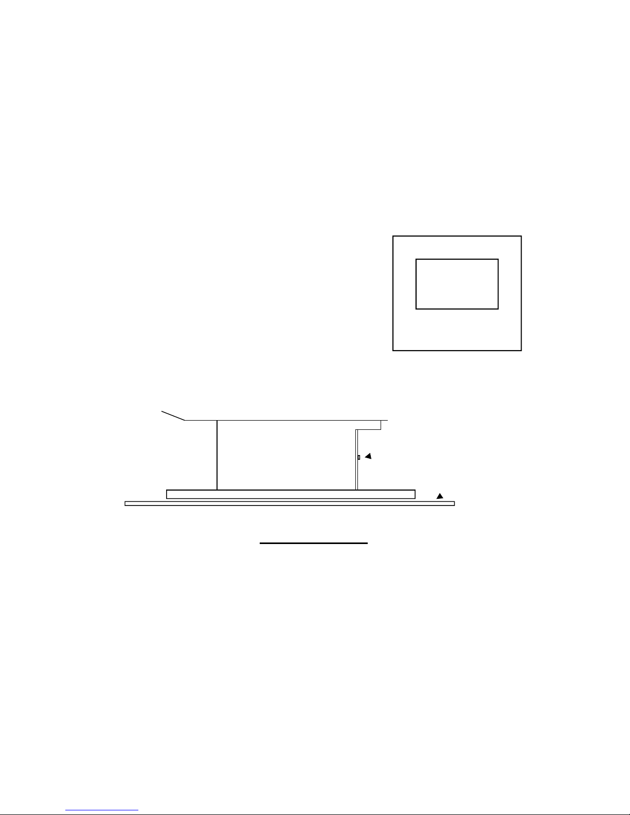
EXAMPLE: Typical hearth pad
(must be non-combustible
and at least 3/8” thick)
NOTE: For residential installation, in which outside air intake is not desired, remove cover-plate at rear of
pedestal base before installing stove as shown below. In this application, a hole through the floor is not required.
INSTALLATION
1. After locating possible obstructions (joists, pipes, etc.) and taking into account the necessary combustible clearances (fig. 2), position the
stove in the intended installation position. Use a plumb line to locate the position of the ceiling hole for the chimney. Size the chimney hole to
the recommended manufacturer’s clearances for your chimney. Mark the hole.
2. If the ceiling is clear of all obstructions, cut out the hole (NOTE: Do not cut the ceiling trusses.).
3. In case of attic space use a plumb line to locate the hole in the roof. Cut out the opening, keeping in mind the chimney manufacturer’s
recommended clearances.
4. If outside air is desired or required by code, locate and cut a 4”diameter hole through the floor anywhere under the pedestal stove base. If air
through the wall is preferred, a dryer-type vent pipe should be installed from the wall to the 3 1/2” diameter hole at the pedestal base back. A
mesh-type screen should be installed to keep out rodents, etc. For your convenience, an outside air kit (part # 4OAVK) is available through
your dealer.
5. Install a hearth pad according to local building codes or manufacturer’s specs (see above figure).
6. Position the stove on the hearth.
7. Check all chimney pipe for damage. Do not use any damaged pipe. Installation procedures may vary from manufacturer to manufacturer of
listed chimney. Install the rest of the chimney up through the hole in the ceiling and roof.
8. In cases when there is an attic space, install a protective joist shield tube or box. Consult local building officials or chimney manufacturer.
9. Install the roof flashing, sealing water tight. Install the storm collar and seal water tight. Install chimney cap. NOTE: Refer to chimney
manufacturer’s specs. Chimney height, see figure 7.
10. Install the stove pipe connector from the stove top to the chimney pipe, making sure to secure all joints of pipe together as well as the pipe
to the stove flue collar with three sheet metal screws at each joint.
11. Call for final inspection.
12. Read completely the operating and burning instructions.
Your wood stove is ready to burn.
16”
6”
6”
6”
Non-combustible hearth pad
Remove air cover plate
at rear of unit.
 Loading...