

Kuma Stoves K-SEQ Installation And Operating Instructions Manual
KUMA STOVES
Rathdrum ID, USA
MODEL# K-SEQ: Sequoia
Tested to: UL1482
Report #: 123-S-04-2
Testing performed by Omni Test Laboratories
INSTALLATION AND OPERATING
SAVE THESE INSTRUCTIONS
INSTRUCTIONS
Rev. 4-18-12

Welcome to the Kuma family.
Kuma is a modified version of the Greek word Kauma that means
“a great heat”.
We would like to take the time to say thank you for
purchasing a Kuma stove. If this is your first Kuma stove, you
have joined a long list of family members, some since 1981. We
are a family business that still desires to maintain a good
relationship with each and every one of our customers. Our
mission is to provide you with a quality product that will last a
lifetime. If you ever have a problem with your stove, we will do
what is needed to get it resolved and keep you warm.
You may have noticed a portion of the Bible enclosed in your
owner’s packet. It is a small gift for you. Our faith in Jesus Christ
is very important to us and we have that faith because there is hope
in heaven. That hope comes from the message of truth that is found
in this gospel of John.
Thank you for allowing us the opportunity to warm your
house. May God bless you and we anticipate that you will enjoy
the use of your new Kuma wood stove.
Sincerely,
The Freeman Family
2

Under Specific test conditions, this heater has been shown to meet
the U.S. Environmental Protection Agency and Washington State
emission limits for residential wood stoves.
Please read the safety precautions and the entire installation and
operation instructions carefully. Failure to properly install and
maintain your wood stove can result in an unsafe condition.
Contents
Section 1…..………………...………….Safety Precautions
Section 2……….……………………..Catalyst Information
Section 3.1……….. Free Standing Installation Instructions
Section 3.2…………………. Insert Installation Instructions
Section 4……………Wood Burning Operation Instructions
Section 5……………………………………....Maintenance
Section 6…………….Installation Clearances and Diagrams
Section 7………………………………..…Troubleshooting
Section 8…………………………...Replacement Parts List
Section 9……………………………………….…Warranty
Section 10……………………………...…EPA Information
3

4

Section 1 – Safety Precautions
5

Install and use in accordance with the manufacturers installation and operation instructions
contained in this manual only.
1. If this stove is not properly installed, a house fire can occur. For your protection, follow the
installation instructions provided. We recommend contacting local building or fire officials
regarding restrictions and installation inspection requirements in your area. We also recommend
that your Kuma model Sequoia stove be installed by a properly trained and licensed
installer, preferably a NFI (National Fireplace Institute) expert.
2. DO NOT CONNECT THIS UNIT TO A CHIMNEY FLUE SERVICING ANOTHER
APPLIANCE.
3. Do not use gasoline, gasoline-type lantern fuel, kerosene, charcoal lighter fluid, or similar liquids
to start or “freshen up” a fire in this heater. Keep all such liquids well away from the heater while
it is in use.
4. Do not burn garbage.
5. DO NOT OVERFIRE. If any part of the stove or chimney glows, the stove is in an overfire
condition. If this happens, shut the air control off immediately.
6. WARNING: DO NOT INSTALL IN A SLEEPING ROOM
7. CAUTION: The structural integrity of the floor, wall and ceiling/roof must be maintained.
8. DO NOT USE SINGLE WALL PIPE FOR ANY CHIMNEY APPLICATION, EXTERIOR
OR THROUGH THE WALL OR CEILING. Single wall pipe may only be used as a
connection between the stove and an approved masonry or stainless steel chimney.
9. When installing into an existing masonry or metal chimney, examine the chimney system
carefully. If you have any questions, seek professional advice. We recommend having existing
chimneys cleaned and inspected by a qualified professional prior to the installation of your new
Stove.
10. NOTE ALL MINIMUM CLEARANCE REQUIREMENTS TO COMBUSTIBLES.
Installation must comply with minumum clearances as listed in this manual. (see section 6)
11. Do not operate this stove with the door in the open position.
12. This stove must be connected to a minimum 8” diameter, U.L.listed type 103HT factory built
chimney, or a code approved masonry chimney. If the masonry chimney does not meet code, a
U.L. 1777 approved liner must be installed. Insert installations should always use a chimney
liner.
13. When connecting single wall or double wall connector pipe to the stove and chimney, use 3
screws per pipe joint including 3 screws securing the pipe to the stove. Depending on the type of
double wall pipe you are using, it may also be necessary to fasten it at the chimney. Simpson
Duravent’s DVL double wall uses a snap lock connector and does not need screws.
14. When connecting this stove to a masonry chimney, make sure you observe all applicable
clearances including walls, ceilings and other combustible material. A masonry chimney must be
minimum 8” diameter and constructed with a liner according to NFPA code 211. If you have any
questions about the condition or the code compliance of your masonry chimney, please speak
with a qualified professional.
15. WHEN PENETRATING A COMBUSTIBLE WALL TO CONNECT TO AN OUTSIDE
MASONRY CHIMNEY YOU MUST BE CERTAIN THAT THE WALL PASS THROUGH
IS A SAFE AND LISTED METHOD. Please refer to NFPA code 211 for details about listed
wall pass through methods. To obtain a copy of the NFPA code 211, you may visit their website
6
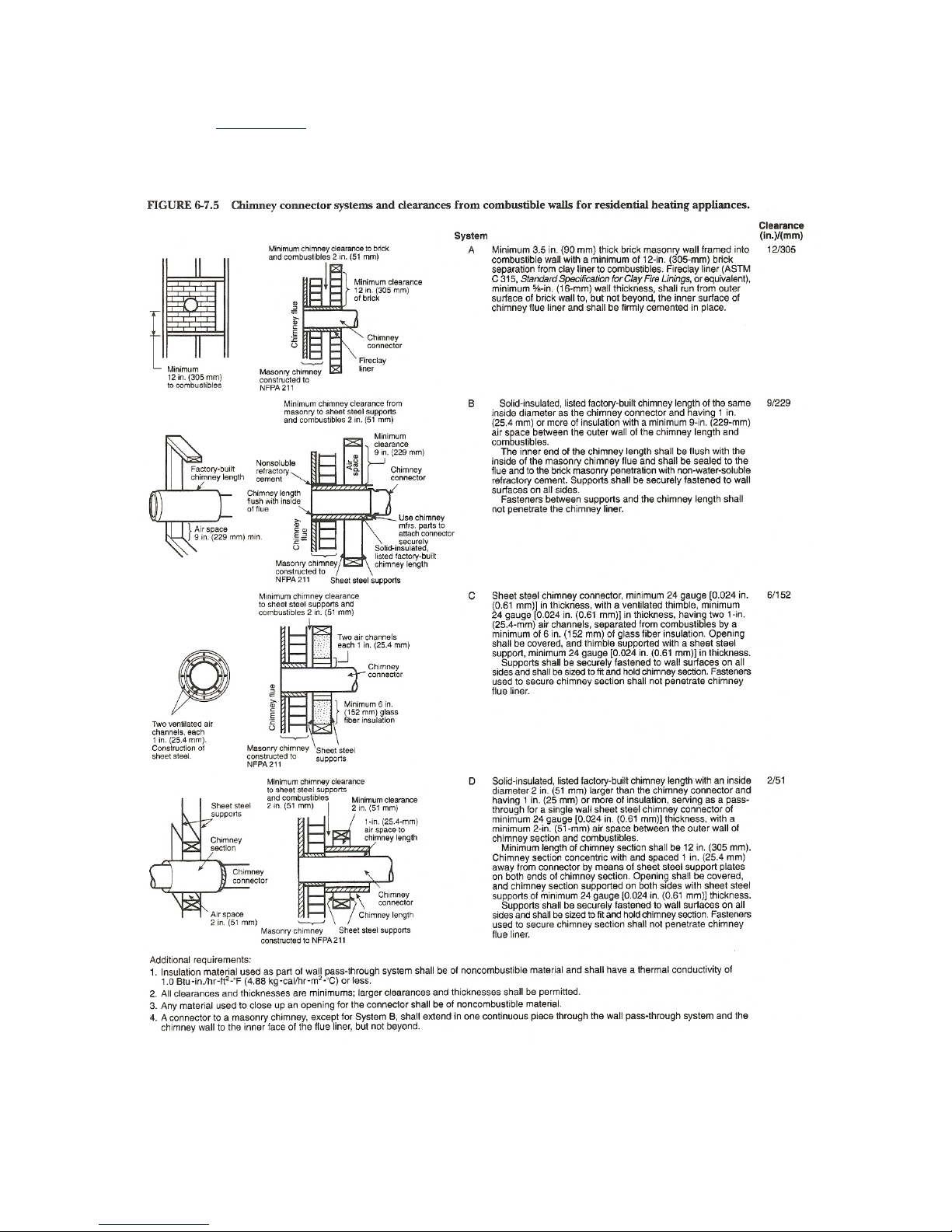
at www.nfpa.org or call them toll free at 1(800)344-3555. Your local b uilding dept. may also
have information regarding NFPA code 211.
EXCERPT FROM NFPA 211
7

Section 2 – Catalyst Information
1. Tamper Warning- This wood stove contains a catalytic combustor which needs periodic
inspection and replacement for proper operation. It is against the law to operate this wood
stove in a manner inconsistent with the operating instructions in this manual, or if the catalytic
element is deactivated or removed.
2. Catalyst type- The combustor supplied with this wood stove is an Applied Ceramics
FireCat® combustor. Please refer to section 5 for catalyst maintenance. Refer to section 7
for catalyst troubleshooting. Refer to section 9 for catalyst warranty information.
3. Catalyst Monitoring- It is important to periodically monitor the operation of the catalytic
combustor to ensure that it is functioning properly, and to determine when it needs to be
replaced. You may also purchase a catalytic probe thermometer which can be used to more
accurately observe and maintain proper catalyst activity. The probe stem must be 3/16”
diameter and between 4” and 5 ½” in length. (Condar brand model: 3-12-1)
Optional Probe installation: To install the probe, remove the metal button on the top plate of
the stove near the flue. Insert the probe through the top plate and into the firebox.
Reading the Probe: Follow the instructions in section 4 to build and maintain a fire. During
normal operation (see section 4) the probe should read between 600 degrees or “active” and
less than 1400 degrees or “too hot” If, during normal operation , the probe reads less than 600
degrees, the stove should be refueled following the instruction in section 4. If the probe is
approaching 1400 degrees, you need to decrease the primary air control so that you do not
over-fire the catalyst. A non-functioning combustor will result in a loss of heating efficiency,
and an increase in creosote and emissions. Combustors should be visually inspected at least
three times during the heating season to determine if physical degradation has occurred.
Actual removal of the combustor is not recommended unless more detailed inspection is
warranted because of decreased performance. See Section 5
8

Section 3.1 –Residential Free Standing Installation
INSTALL AND USE IN ACCORDANCE WITH THE MANUFACTURER’S INSTALLATION
AND OPERATING INSTRUCTIONS ONLY. WHILE MOST ANYONE WITH BASIC
CARPENTRY SKILLS CAN SUCCESSFULLY AND SAFELY INSTALL THEIR KUMA WOOD
STOVE, IT IS HIGHLY RECOMMENDED THAT IT IS INSTALLED BY A QUALIFIED
PROFESSIONAL WHO IS PROPERLY TRAINED AND LICENSED–PREFERABLY AN NFI
CERTIFIED (NATIONAL FIREPLACE INSTITUE) EXPERT.
CAUTION: The Structural integrity of the home floor, walls, and ceiling/roof must be maintained. Use
additional bracing if required. Never cut a load bearing wall or engineered truss, use elbows if necessary to
offset the pipe.
CAUTION: NEVER INSTALL A STOVE IN A SLEEPING ROOM. DO NOT INSTALL THIS UNIT
IN A MOBILE OR MANUFACTURED HOME
Free Standing Installation:
Step 1: Determining the stove location:
When choosing a stove location there are a few things that should be considered.
1. Try to choose a location that is centrally located in the house.
2. Try to choose a location that will be easy to access from your wood storage area.
3. Survey the roof area above and around the location of the chimney exit. Be su re there are no
dormers, roof valleys or any other roof irregularities that could cause difficulty when trying to set
and seal the roof flashing.
4. If possible, survey the attic area above and around the location of the chimney. Be sure there are
no major obstructions such as plumbing, heating ducts, electrical wires, phone cables, etc. Also
check the crawl space below and around the stove location for the same obstructions.
STEP 2: Installing the chimney.
Use only 8” Class A solid fuel chimney that has been U.L. safety tested for wood stoves (type 103 HT)
IMPORTANT: These instructions are a very basic guideline for the steps to install your chimney.
For complete instructions, refer to the installation manual that came with your chimney. Chimney
installation instructions are usually located in the box with the chimney cap or chimney support
components. DO NOT mix different brands of chimney components. If you have any questions about
the installation of your chimney, please contact the dealer where you purchased your stove.
CAUTION: Inspect all chimney components for damage. Do not use any damaged chimney
components.
Installing the chimney
CAUTION: Inspect all chimney components for damage. Do not use any damaged chimney
components.
1. Familiarize yourself with the clearances of the stove for the configuration in which you have
chosen to install, i.e. corner installation or straight wall installation (see section 6). Notice the
clearances listed for the chimney, this will help you determine the location of the hole in the
ceiling. Note: On metal roofs in snow regions, consideration must be given to snow loads above
9
 Loading...