

Kuma Stoves K-ASH Installation And Operating Instructions Manual
KUMA STOVES
50145 N Old Hwy 95
Rathdrum ID 83858
MODEL# K-ASH: Ashwood
Tested to: UL 1482-1996
Test Report #: 123-S-08-2
Tested and listed by Omni Test Laboratories
INSTALLATION AND OPERATING
SAVE THESE INSTRUCTIONS
INSTRUCTIONS
Rev. 1-10-13

Welcome to the Kuma family.
Kuma is a modified version of the Greek word Kauma which
means
“a great heat”.
We would like to take the time to say thank you for
purchasing a Kuma stove. If this is your first Kuma stove, you
have joined a long list of family members, some since 1981. We
are a family business that still desires to maintain a good
relationship with each and every one of our customers. Our
mission is to provide you with a quality product that will last a
lifetime. If you ever have a problem with your stove, we will do
what is needed to get it resolved and keep you warm.
You may have noticed a portion of the Bible enclosed in your
owner’s packet. It is a small gift for you. Our faith in Jesus Christ
is very important to us and we have that faith because salvation
and hope are found through Him. Hope comes from the message of
Truth that is found in this New Testament.
Thank you for allowing us the opportunity to warm your
home. May God bless you, and we anticipate that you will enjoy
the use of your new Kuma wood stove.
Sincerely,
The Freeman Family
2

Under specific test conditions, this heater has been shown to meet
the U.S. Environmental Protection Agency and Washington State
emission limits for residential wood stoves.
Please read the safety precautions and the entire installation and
operation instructions carefully. Failure to properly install and
maintain your wood stove can result in an unsafe condition.
Consult your local building department for permit and
installation requirements.
Contents
Section 1…..….……………………...………….Safety Precautions
Section 2………………... Free-standing Installation Instructions
Section 3.1 ……………Masonry Fireplace Installation Instructions
Section 3.2………..Factory Built Fireplace Installation Instructions
Section 4……………………Wood Burning Operation Instructions
Section 5……………………………………………....Maintenance
Section 6…………………….Installation Clearances and Diagrams
Section 7………………………………………..…Troubleshooting
Section 8…………………………………...Replacement Parts List
Section 9……………………………………………….…Warranty
Section 10……………………………………...…EPA Information
3
Section 1 – Safety Precautions
Install and use in accordance with the manufacturers installation and operation
instructions contained in this manual only.
1. If this stove is not properly installed, a house fire can occur. For your protection, follow the installation
instructions provided. We recommend contacting local building or fire officials regarding restrictions and
installation inspection requirements in your area. We also recommend that your Kuma stove be installed
by a properly trained and licensed installer, preferably an NFI (National Fireplace Institute) expert.
2. DO NOT CONNECT THIS UNIT TO A CHIMNEY FLUE SERVICING ANOTHER APPLIANCE.
3. Do not burn garbage or flammable fluids such as gasoline, naptha or engine oil. Do not use charcoal
lighter fluid or similar liquids to start or “freshen up” a fire in this heater. Keep all such fluids well away
from the heater while in use. Storing these fluids near a stove could cause a fire.
4. DO NOT CONNECT TO ANY AIR DISTRIBUTION OR DUCT SYSTEM.
5. DO NOT OVERFIRE. If any part of the stove or chimney glows, the stove is in an overfire condition. If
this happens, shut the air control off immediately. Over firing can cause damage.
6. WARNING: DO NOT INSTALL IN A SLEEPING ROOM
7. CAUTION: THE STRUCTURAL INTEGRITY OF THE FLOOR, WALLS, AND ROOF/CEILING
MUST BE MAINTAINED.
8. DO NOT USE SINGLE WALL PIPE FOR ANY CHIMNEY APPLICATION, EXTERIOR OR
THROUGH THE WALL OR CEILING. Single wall pipe may only be used as a connection between the
stove and an approved masonry or stainless steel chimney. Single wall pipe may not be used as a
connector in mobile homes.
9. When installing into an existing masonry or metal chimney, examine the chimney system carefully. If you
have any questions, seek professional advice. We recommend having existing chimneys cleaned and
inspected by a qualified professional prior to the installation of your new stove.
10. NOTE ALL MINIMUM CLEARANCE REQUIREMENTS TO COMBUSTIBLES. Installation must
comply with minimum clearances as listed in this manual. (see section 6) Clearances may only be reduces
by means approved by the regulatory authority.
11. Do not operate this stove with the door in an open position, except for cracking open during start-up.
Continued operation with the door open can cause overheating of the unit, and expose embers to nearby
combustibles.
12. Do not operate this stove with the ash pan open. Regularly check seal and replace as needed
13. Do not operate with broken glass. Do not abuse glass such as striking or slamming the door.
14. This stove must be connected to a minimum 6” diameter listed chimney that complies with U.L. type 103HT
factory built chimney or a code approved masonry chimney. If the masonry chimney does not meet code, a
U.L. 1777 approved liner must be installed.
15. When connecting single wall or double wall connector pipe to the stove and chimney, use 3 screws per pipe
joint including 3 screws securing the pipe to the stove. Depending on the type of double wall pipe you are
using, it may also be necessary to fasten it at the chimney. Simpson Duravent’s DVL double wall uses a
snap lock connector and does not need screws.
16. Use only approved components for Chimney and Connector. Field fabricated or “makeshift” components
are not allowed and can cause a fire.
17. DO NOT USE THIS STOVE WITHOUT INSTALLING THE BAFFLE BOARDS AND CERAMIC
INSULATION PACKAGED WITH YOUR STOVE.
18. When connecting this stove to a masonry chimney, make sure you observe all applicable clearances
including walls, ceilings and other combustible material. A masonry chimney must be minimum 6” diameter
and constructed with a liner according to NFPA code 211. If you have any questions about the condition or
the code compliance of your masonry chimney, please speak with a qualified professional.
4
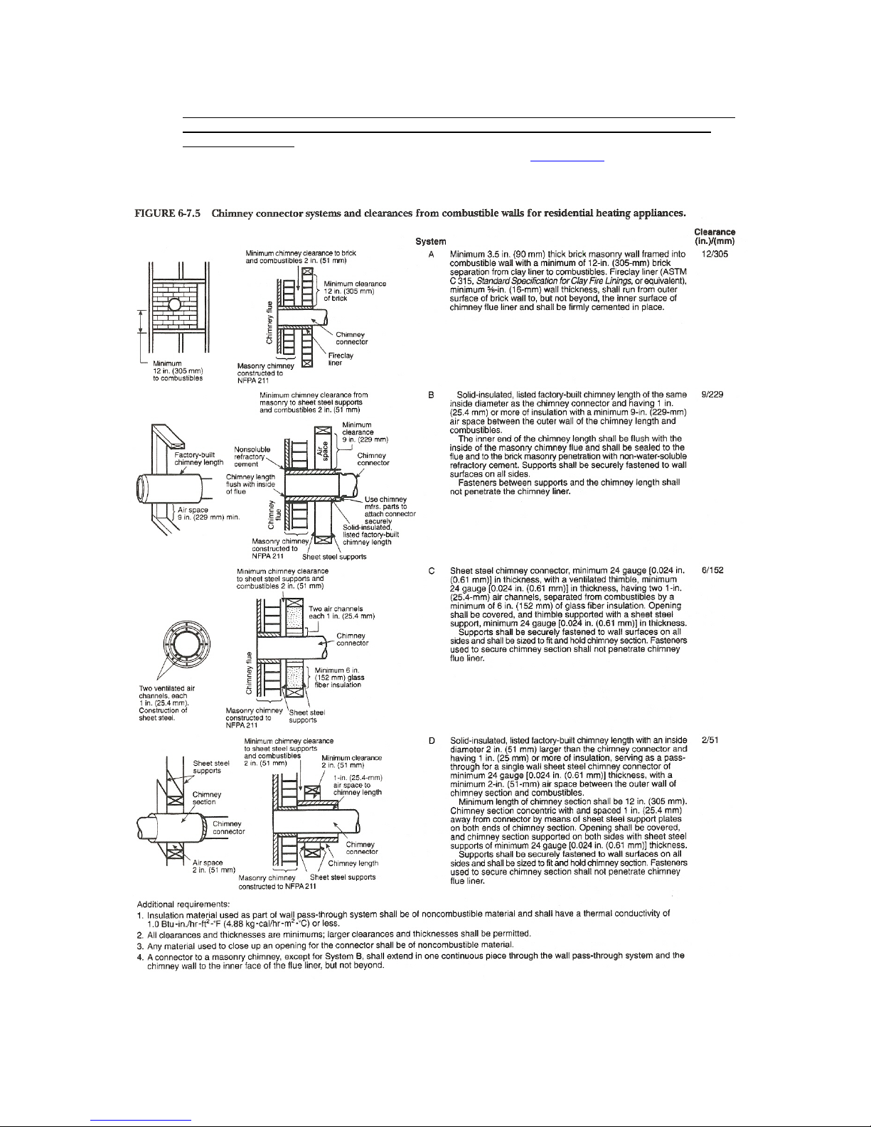
19. WHEN PENETRATING A COMBUSTIBLE WALL TO CONNECT TO AN OUTSIDE MASONRY
CHIMNEY YOU MUST BE CERTAIN THAT THE WALL PASS THROUGH IS A SAFE AND
LISTED METHOD. Please refer to NFPA code 211 for details about listed wall pass through methods. To
obtain a copy of the NFPA code 211, you may visit their website at www.nfpa.org or call them toll free at
1(800)344-3555. Your local building deptartment may also have information regarding NFPA code 211.
Excerpt from NFPA 211
5

Section 2 – Installation Instructions
INSTALL AND USE IN ACCORDANCE WITH THE MANUFACTURER’S INSTALLATION
AND OPERATING INSTRUCTIONS ONLY. WHILE MOST ANYONE WITH BASIC
CARPENTRY SKILLS CAN SUCCESSFULLY AND SAFELY INSTALL THEIR KUMA WOOD
STOVE, IT IS HIGHLY RECOMMENDED THAT IT IS INSTALLED BY A QUALIFIED
PROFESSIONAL WHO IS PROPERLY TRAINED AND LICENSED–PREFERABLY AN NFI
CERTIFIED (NATIONAL FIREPLACE INSTITUE) EXPERT.
CAUTION: The structural integrity of the floor, walls and ceiling/roof must be maintained. Use
additional bracing if required. Never cut a load bearing wall or engineered truss. Use elbows if necessary
to offset the pipe.
CAUTION: In Canada only: DO NOT INSTALL IN A MOBILE HOME.
CAUTION: NEVER INSTALL A STOVE IN A SLEEPING ROOM.
Stove Components: (each component has installation instructions included. See sec. 8 for a complete
list of accessories)
1. Stove body (K ASH)
2. Pedestal or leg kit (KA PK 1, KA LG SB, etc.)
3. Door Kit (KA DR 2B, KA DR 2G, etc.)
4. Ashpan Assembly (KA AP 1)
5. Outside air kit (KA OA 1)
6. Optional Blower (KA BL 2)
7. Fireplace surround kit (KA FS 1P)
STEP 1: DETERMINING THE STOVE LOCATION:
When choosing a stove location there are a few things that should be considered.
1. Try to choose a location that is centrally located in the house.
2. Try to choose a location that will be easy to access from your wood storage area.
3. Survey the roof area above and around the location of the chimney exit. Be sure there are no
dormers, roof valleys or any other roof irregularities that could cause difficulty when trying to set
and seal the roof flashing.
4. If possible, survey the attic area above and around the location of the chimney. Be sure there are
no major obstructions such as plumbing, heating ducts, electrical wires, phone cables, etc. Also
check the crawl space below and around the stove location for the same obstructions.
STEP 2: INSTALLING THE CHIMNEY.
Use only 6” Class A solid fuel chimney that has been U.L. Safety tested for wood stoves (type 103 HT)
IMPORTANT: These instructions are a very basic guideline for the steps to installing your chimney.
For complete, step by step instructions, refer to the installation manual that came with your chimney.
Chimney installation instructions are usually located in the box with the chimney cap or chimney
support components. If you have any questions about the installation of your chimney, please
contact the dealer where you purchased your stove.
CAUTION: Use only pre-fabricated, listed chimney and connector components. Field fabricated
components and/or “makeshift” compromises could result in a chimney or house fire.
6

CAUTION: Inspect all chimney components for damage. Do not use any damaged chimney
components.
1. Familiarize yourself with the clearances of the stove for the configuration in which you have
chosen to install, i.e. corner installation or straight wall installation (see section 6). Notice the
clearances listed for the chimney, this will help you determine the location of the hole in the
ceiling. Note: On metal roofs in snow regions, consideration must be given to snow loads above
the chimney that can slide in to chimney and severely damage it. Please consider snow breaks or
snow dividers to prevent damage.
2. Once you’ve determined the stove location based on the applicable clearances and connector type
(see section 6), be sure to check attic and roof for any obstructions. Install the chimney system
according to the step by step illustrated instructions that came with your chimney.
3. Special care needs to be exercised when passing the chimney through an attic space. An attic
insulation shield must be used in all chimney installations to ensure that no insulation can contact
the chimney pipe. If there is little or no attic space, or if you have a vaulted ceiling, use a tall
square cathedral ceiling support box to pass all the way through to the roof lin e to pro vide the
shielding.
4. Stability: If necessary, install a roof brace kit on the chimney to stabilize the chimney against
wind, etc. Generally, roof bracing is required if the chimney extends more than five feet above the
chimney exit point.
5. See illustrations in section 6, page 18, for all components required for factory-built chimneys, as
well as parts required to connect to an approved masonry chimney.
6. Chimney Height. Page 18 shows the minimum chimney height in relation to the roof. With low
pitch roofs or little attic space, the chimney can be too short. For proper draft and best
performance, a minimum overall height of connector pipe plus chimney combined should be at
least 12 feet tall, measured from the stove top to the chimney cap. If necessary, add chimney.
STEP 3: OUTSIDE AIR
Outside Air – Outside air is required in all manufactured home installations.
1. Kuma Stoves does not particularly require that outside air be directly connected to this stove
however, some state or local building codes may mandate outside air. If your state or local
building code requires an outside air supply use part# KA OA 1. If you are unable to supply a
direct connection to the stove, we suggest the following:
a. Provide a passive air supply to the home. The air vent should be a minimum of 4” in
diameter.
b. The air supply must be provided to the same room that the stove is installed in.
c. Th e air supply should utilize a baro metric damper so that air is only supplied to the room
if the house pressure becomes negative.
Visit www.woodheat.org for more information on the use of outside air.
2. When building a hearth pad on site, be sure to leave an area open for the installation of the
outside air vent. Once the hearth is positioned according to the minimum clearances, locate and
mark out the hole for the 4” outside are vent. On a pedestal model stove, this hole may be
anywhere under the stove base. On a leg model stove, try and locate the hole to line up with the
hole in the bottom of the stove. On a pre-manufactured hearth, use a hole saw or circular saw to
cut through just the backing board then use a hammer and firmly hit the tile or stone on the top
side. If the backing board was cut to the correct depth, the tile or stone will break out very clean.
Also using a hole saw or circular saw cut the hole through the home floor into the crawl space. Be
sure to line this hole up with the one in the hearth.
3. If you are installing your outside air vent through the wall, use a 4” hole saw or reciprocating saw
to cut the hole through the wall. BE SURE TO CHECK FOR OBSTRUCTIONS IN THE
WALL.
7
STEP 4: INSTALLING THE HEARTH
CAUTION: The Kuma Ashwood Stove can be configured as a Freestanding Stove or as a Fireplace Insert.
Freestanding Stoves can be supported by either Legs or a Pedestal Base. Each configuration has different
floor protection requirements. See the section below that pertains to your particular installation.
Minimum Requirements:
The minimum floor protection requirements for the Kuma Ashwood model are as follows:
Floor protection must consist of a continuous non-combustible material and extend a minimum of 16" in
front of the loading door and 6” to both sides and the re ar of the stove body.
Additional requirements for material thickness and thermal resistance are described below.
1. Ashwood with Pedestal Base: Installed as a freestanding stove on a pedestal base the Kuma
Ashwood requires Ember Protection only. Ember Protection can take the recommended form of a
manufactured Type-1 floor protector listed to UL-1618, or a non-combustible continuous material
with a MINIMUM thickness of 3/8”.
2. Ashwood with Legs: Installed as a freestanding stove on legs the Kuma Ashwood requires both
continuous ember protection and Thermal Protection with a minimum R-Value of 0.60. Thermal
Protection can take the recommended form of a manufactured Type-2 floor protector listed to UL-
1618 with a tested R-Value higher than R = 0.60. Alternately a site built or existing hearth can be
used provided they meet the minimum size and thermal resistance requirements. Never install this
stove with legs on an existing hearth unless you can determine it provides a minimum thermal
resistance of R = 0.60.
3. Ashwood Insert: The Ashwood can be installed as a fireplace insert in either a masonry fireplace
in good condition or a factory-built fireplace which is approved for the installation of a fireplace
insert. Minimum floor protection requirements are as follows:
a. Minimum 1” continuous non-combustible material under the insert and extending at least 17”
in front of the insert face, and 8” to either side of the insert (that is 17” is measured from the
face of the insert and not the ash lip). This 1” thick material must have an R-Value of R
=1.2or greater.
b. An Ashwood insert which, when installed, extends out from the fireplace face, but does not
rest on the hearth in front, and has at least 2” of airspace between the hearth and the
bottom of the insert bottom, requires ember protection only (Type-1 UL Listed Hearth
Protector or continuous non-combustible material.) This type of installation is more
common in factory-built fireplaces.
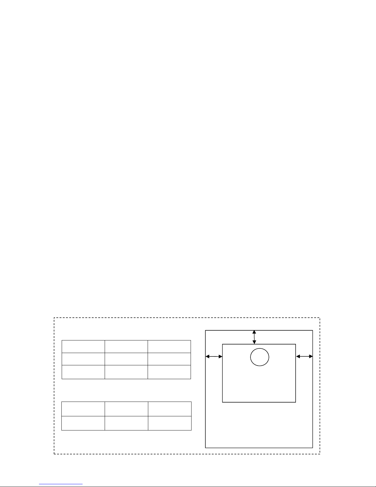
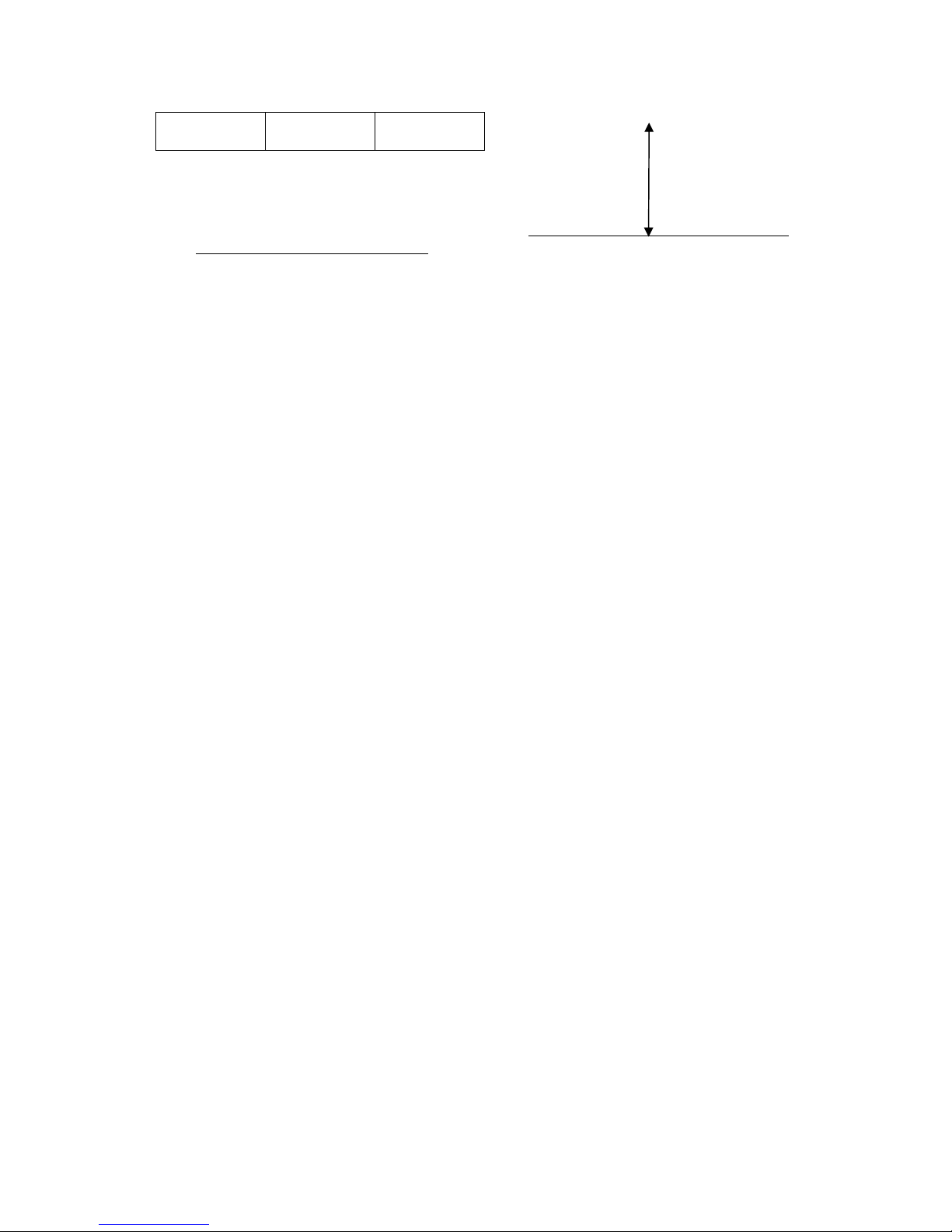
MINIMUM Floor Protection size Requirements.
For Free Standing Stove.
a
a
USA
a 6”
b 16”
For Fireplace insert
a
USA
a 8”
8
b 17”
STEP 5: Setting the stove and connecting to the chimney
1. Assemble the stove (legs, pedestal, ash pan, blower). Follow the installation instructions that
are included in each accessory box. Once the stove is assembled set the stove gently on the
hearth using cardboard to protect the hearth.
2. Position the stove on the hearth according to the clearances shown on the diagrams in section 6.
Be sure that the stove is at least minimum clearance from all combustible walls and materials. If
possible it is advisable to set the stove 1-2 inches further away from the combustibles than
required.
3. Using approved single (min. 24 MSG Black or 26 MSG Blued)- or double-wall pipe, (single wall
is not approved for a mobile home) connect the stove to the chimney. If necessary, use elbows to
offset the pipe so that the stove can remain at the correct clearance and still connect to the
chimney. Secure each pipe joint with three screws, using the screws provided with the pipe.
Secure the pipe to stove flue collar with 3 screws.
4. If installing in a mobile home, drill a small hole through the hearth and route the 8 gauge copper
wire into the crawl space. Use a grounding “connector” or “lug” to attach the ground wire to the
stove and to the frame of the mobile home.
5. When required by local code, you will need to fasten the stove to the floor of the mobile home.
(This applies to mobile homes only). To fasten a leg model, simply mark the location of the hole
in the bottom of the legs, drill holes and bolt into the bottom of the leg from the crawl space. To
fasten a pedestal model, holes will need to be drilled in the pedestal base. Once the holes are
drilled in the base, mark the location on the floor and use bolts and nuts or lag screws to fasten.
Your stove is now ready for use. If your stove installation required a permit and requires inspectio n by the
local building department please do not forget to call for an inspection. It is important that your permit and
inspection be finalized, as some insurance companies will require the stove to be inspected. It is also a
great idea to give your insurance a call and let them know that you have installed a wood stove.
PLEASE REFER TO SECTION 4-“Wood Burning Operation Instructions” as well as “Before Operating”
checklist before lighting your first fire.
b
9
 Loading...