


OPERATING HANDBOOK
KR C2
Machine Data
Issued: 05 Feb 2005 Version: 00
Maschi nendaten 12.0400 en
1of 91

e Copyright KUKA Roboter GmbH
This documentation or excerpts therefrom may not be reproduced or disclosed to third parties without the express permission of the publishers.
Other functions not described in this documentation may be operable in the controller. The user has no claim to these functions, however, in
the case of a replacement or service work.
We have checked the content of this documentation for conformity with the hardware and software described. Nevertheless, discrepancies
cannot be precluded, for which reason we are not able to guarantee total conformity. The information in this documentation is checked on a
regular basis, however, and necessary corrections will be incorporated in subsequent editions.
Subject to technical alterations without an effect on the function.
PD Interleaf
Maschi nendaten 12.0400 en
2of 91

Contents
1 Introduction 8.....................................................
1.1 Characteristics 8................................................................
1.2 System requirements 8...........................................................
1.2.1 Software 8......................................................................
1.2.2 Hardware 8.....................................................................
2 The file $MACHINE.DAT 9..........................................
2.1 Description of the individual machine data 9.........................................
2.1.1 $V_R1MADA[ ] 9................................................................
2.1.2 $TECH_MAX 9..................................................................
2.1.3 $NUM_AX 10....................................................................
2.1.4 $AXIS_TYPE[ ] 10................................................................
2.1.5 $COUP_COMP[ ] 11..............................................................
2.1.6 $EXCOUP_COMP[ ] 11...........................................................
2.1.7 $MAMES[ ] 12...................................................................
2.1.8 $ROBROOT 13..................................................................
2.1.9 $ERSYSROOT 14................................................................
2.1.10 $RAT_MOT_AX[ ] 15..............................................................
2.1.11 $RAT_MOT_ENC[ ] 16............................................................
2.1.12 $DSECHANNEL[ ] 16.............................................................
2.1.13 $PMCHANNEL[ ] 18..............................................................
2.1.14 $LOOP_LG_PTP[ ] 19............................................................
2.1.15 $LOOP_G_VEL_PTP[ ] 19.........................................................
2.1.16 $LOOP_I_VEL_PTP[ ] 20..........................................................
2.1.17 $LOOP_DIRECTION[ ] 20.........................................................
2.1.18 $SLAVE_LOOP_FOL_CRITICAL[ ] 20...............................................
2.1.19 $SLAVE_LOOP_FOL_ALARM[ ] 21.................................................
2.1.20 $SLAVE_LOOP_SPEED_ALARM[ ] 21..............................................
2.1.21 $SLAVE_LOOP_PMCHANNEL[Ln] 21...............................................
2.1.22 $LOOP_TYPE[Ln] 21.............................................................
2.1.23 $LOOP_TYPE_ATTRIBUTE[ ] 22...................................................
2.1.24 $MASTER_LOOP[Ln] 22..........................................................
2.1.25 $SLAVE_TORQUE_RA TIO[ ] 23....................................................
2.1.26 $NINPUT_SENSORTYPE[Ln] 23...................................................
2.1.27 $NINPUT_SENSORCHANNEL[Ln] 24...............................................
2.1.28 $NINPUT_SUBCHANNEL[Ln] 24...................................................
2.1.29 $POSINPUT_SENSORTYPE[Ln] 25................................................
2.1.30 $POSINPUT_SENSORCHANNEL[Ln] 25............................................
2.1.31 $POSINPUT_SUBCHANNEL[Ln] 25................................................
2.1.32 $TORQINPUT_SENSORTYPE[Ln] 26...............................................
2.1.33 $LOOP_RAT_MOT_AX[ ] 26.......................................................
2.1.34 $LOOP_RAT_EXTPOS_AX[ ] 26...................................................
2.1.35 $MOTOR_POLE_NUMBER[ ] 27...................................................
2.1.36 $SERVOFILE_CONFIG[ ] 27.......................................................
2.1.37 $SERVOFILEKPS1[ ] 27..........................................................
2.1.38 $CURR_MAX[ ] 28................................................................
2.1.39 $CURR_CAL[ ] 28
2.1.40 $CURR_LIM[i] 29.................................................................
2.1.41 $CURR_MON[i] 29...............................................................
................................................................
Maschi nendaten 12.0400 en
3of 91

Machine Data
2.1.42 $KPS_CURR_MAX 30............................................................
2.1.43 $KPS_CURR_RA TED 30..........................................................
2.1.44 $CURR_COM_EX[ ] 30............................................................
2.1.45 $KT_MOT[ ] 31...................................................................
2.1.46 $KT0_MOT[ ] 31..................................................................
2.1.47 $RAISE_TIME[ ] 31...............................................................
2.1.48 $RAISE_T_MOT[ ] 32.............................................................
2.1.49 $VEL_AXIS_MA[ ] 32.............................................................
2.1.50 $VEL_CPT1_MA 33..............................................................
2.1.51 $VEL_DSE_MA[ ] 33..............................................................
2.1.52 $AXIS_RESO[ ] 33...............................................................
2.1.53 $RED_VEL_AXC[ ] 34.............................................................
2.1.54 $RED_ACC_AXC[ ] 34............................................................
2.1.55 $RED_ACC_DYN 35..............................................................
2.1.56 $RED_VEL_CPC 35..............................................................
2.1.57 $RED_ACC_CPC 35..............................................................
2.1.58 $VEL_CP_T1 35.................................................................
2.1.59 $VEL_CP_COM 35...............................................................
2.1.60 $RED_JUS_UEB 36..............................................................
2.1.61 $RED_ACC_OV[ ] 36.............................................................
2.1.62 $ACC_CAR_TOOL 36............................................................
2.1.63 $ACC_CAR_LIMIT 37.............................................................
2.1.64 $ACC_CAR_ACT 37..............................................................
2.1.65 $ACC_CAR_STOP 37............................................................
2.1.66 $RED_ACC_EMX[ ] 38............................................................
2.1.67 $WARMUP_RED_VEL 38.........................................................
2.1.68 $WARMUP_TIME 39..............................................................
2.1.69 $COOLDOWN_TIME 39...........................................................
2.1.70 $WARMUP_CURR_LIMIT 39......................................................
2.1.71 $WARMUP_MIN_FAC 39..........................................................
2.1.72 $WARMUP_SLEW_RATE 39......................................................
2.1.73 $ST_TOL_VEL[ ] 40..............................................................
2.1.74 $ST_TOL_TIME 40...............................................................
2.1.75 $BOUNCE_TIME
2.1.76 $VEL_AX_JUS[ ] 41..............................................................
2.1.77 $SEN_DEL[ ] 41..................................................................
2.1.78 $L_EMT_MAX[ ] 42...............................................................
2.1.79 $G_VEL_CAL 42.................................................................
2.1.80 $LG_PTP[ ] 42...................................................................
2.1.81 $LG_CP[ ] 43....................................................................
2.1.82 $TC_SYM 43....................................................................
2.1.83 $DECEL_MB[ ] 43................................................................
2.1.84 $G_COE_CUR 44................................................................
2.1.85 $G_VEL_PTP[ ] 44...............................................................
2.1.86 $G_VEL_CP[ ] 44................................................................
2.1.87 $I_VEL_PTP[ ] 45................................................................
2.1.88 $I_VEL_CP[ ] 45.................................................................
2.1.89 $VEL_FILT[ ] 46..................................................................
2.1.90 $TM_CON_VEL 46...............................................................
2.1.91 $APO_DIS_PTP[ ] 46.............................................................
2.1.92 $ACC_MA 47....................................................................
2.1.93 $VEL_MA 47.....................................................................
2.1.94 $ACC_OV 48....................................................................
2.1.95 $RED_T1 48.....................................................................
41..............................................................
4of 91
Maschi nendaten 12.0400 en

2.1.96 $DEF_FLT_PTP 48...............................................................
2.1.97 $DEF_FLT_CP 48................................................................
2.1.98 $DEF_OV_JOG 49...............................................................
2.1.99 $ANA_DEL_FLT 49...............................................................
2.1.100 $SEQ_CAL 49...................................................................
2.1.101 $DIR_CAL 49....................................................................
2.1.102 $RED_CAL_SD 50...............................................................
2.1.103 $RED_CAL_SF 50................................................................
2.1.104 $BRK_MODE 50.................................................................
2.1.105 $BRK_OPENTM 52...............................................................
2.1.106 $BRK_DEL_COM 52..............................................................
2.1.107 $BRK_DEL_PRO 53..............................................................
2.1.108 $BRK_DEL_EX 54................................................................
2.1.109 $SERV_OFF_TM 54..............................................................
2.1.110 $MS_DA 54......................................................................
2.1.111 $FFC_VEL 55....................................................................
2.1.112 $FFC_TORQ 55..................................................................
2.1.113 $GEARTORQ_MON 55...........................................................
2.1.114 $SERVOMODE 56................................................................
2.1.115 $ACC_ACT_MA 56...............................................................
2.1.116 $VEL_ACT_MA 56................................................................
2.1.117 $IN_POS_CAR 57................................................................
2.1.118 $IN_POS_ORI 57................................................................
2.1.119 $IN_POS_MA[ ] 58...............................................................
2.1.120 $TIME_POS[ ] 59.................................................................
2.1.121 $IN_STILL_MA 59................................................................
2.1.122 $FOL_ERR_MA[ ] 60.............................................................
2.1.123 $VEL_ENC_CO 60...............................................................
2.1.124 $COM_VAL_MI[ ] 60..............................................................
2.1.125 $TL_COM_VAL 61................................................................
2.1.126 $TOUCH_VEL 61.................................................................
2.1.127 $TOUCH_ACC 61................................................................
2.1.128 $SOFTN_END[ ] 61...............................................................
2.1.129 $SOFTP_END[ ] 62
...............................................................
2.1.130 $AXWORKSPACE 62.............................................................
2.1.131 $BRK_MAX_TM 62...............................................................
2.1.132 $EMSTOP_TIME 63..............................................................
2.1.133 $ACT_VAL_DIF 63...............................................................
2.1.134 $TRAFONAME 63................................................................
2.1.135 $KINCLASS 63...................................................................
2.1.136 $AX_SIM_ON 64.................................................................
2.1.137 $SIMULATED_AXIS 64............................................................
2.1.138 $TRAFO_AXIS 65................................................................
2.1.139 $MAIN_AXIS 65..................................................................
2.1.140 $WRIST_AXIS 69................................................................
2.1.141 $A4_PAR 69.....................................................................
2.1.142 $DEF_A4FIX 70..................................................................
2.1.143 $DEF_A5LINK 70.................................................................
2.1.144 $SPINDLE 71....................................................................
2.1.145 $AXIS_SEQ 71...................................................................
2.1.146 $AXIS_DIR[ ] 72..................................................................
2.1.147 $INC_AXIS 72...................................................................
2.1.148 $INC_EXTAX[ ] 73................................................................
2.1.149 $INC_CAR[ ] 73..................................................................
Maschi nendaten 12.0400 en
5of 91

Machine Data
2.1.150 $POS_SWB[ ] 73.................................................................
2.1.151 $SINGUL_POS 74................................................................
2.1.152 $DIS_WRP1 74..................................................................
2.1.153 $DIS_WRP2 74..................................................................
2.1.154 $ORI_CHECK 75.................................................................
2.1.155 $TIRORO 75.....................................................................
2.1.156 $TFLWP 76......................................................................
2.1.157 $TX3P3 76......................................................................
2.1.158 $LENGTH_A 76..................................................................
2.1.159 $LENGTH_B 76..................................................................
2.1.160 $DH_4 77.......................................................................
2.1.161 $DH_5 77.......................................................................
2.1.162 $SPIN_A 78.....................................................................
2.1.163 $SPIN_B 78.....................................................................
2.1.164 $SPIN_C 78.....................................................................
2.1.165 $TRP_A 78......................................................................
2.1.166 $SPC_KIN 79....................................................................
2.1.167 $ASR_ERROR 79................................................................
2.1.168 $RAT_EXT_ENC 79..............................................................
2.1.169 $AX_ENERGY_MAX[ ] 80.........................................................
2.1.169.1Kinetic energy 80.................................................................
2.1.169.2Potential energy 81...............................................................
2.1.169.3Maximum energy of the linear unit 81................................................
2.1.169.4Maximum energy of a turntable 81..................................................
2.1.170 $BRK_ENERGY_MAX[ ] 81........................................................
2.1.171 $BRK_COOL_OFF_COEFF[ ] 81...................................................
2.1.172 $BRK_TORQUE[ ] 82.............................................................
2.2 Machine data for external axes 83..................................................
2.2.1 $EX_AX_NUM 83................................................................
2.2.2 $EX_AX_ASYNC 83..............................................................
2.2.3 $ASYNC_T1_FAST 84............................................................
2.2.4 $ASYNC_EX_AX_DECOUPLE 86..................................................
2.2.4.1 Interaction with system variables 87.................................................
2.2.5 $EX_KIN 88.....................................................................
2.2.6 $ET1_AX 88.....................................................................
2.2.7 $ET1_NAME[ ] 89................................................................
2.2.8 $ET1_TA1KR 89.................................................................
2.2.9 $ET1_TA2A1 89..................................................................
2.2.10 $ET1_TA3A2 90..................................................................
2.2.11 $ET1_TFLA3 90..................................................................
2.2.12 $ET1_TPINFL 91.................................................................
6of 91
Maschi nendaten 12.0400 en

Maschi nendaten 12.0400 en
7of 91

Machine Data
1 Introduction
Incorrect modifications to the machine data can cause the robot to malfunction.
Robot malfunctions constitute a risk of danger to life and limb.
1.1 Characteristics
The robot--specific file $machine.dat contains important configuration data that are required
for operation of the robot hardware.
The drives, motors and axis kinematic systems are defined in the f ile $machine.dat.
All the machine data contained in the file $machine.dat are described in this documentation.
1.2 System requirements
1.2.1 Software
This description is valid from:
KR C2 system software release 5.2
1.2.2 Hardware
G Controller type KR C2
Special training is required for configuring machine data.
Advanced knowledge of KR C... robot controllers and their configuration and programming
is required.
8of 91
Maschi nendaten 12.0400 en

2 The file $MACHINE.DAT
Val
Val
The machine data dealt with in this documentation also include the necessary
addresses for the configuration of external drive boxes. These additional data are
always specially indicated in this documentation.
2.1 Description of the individual machine data
2.1.1 $V_R1MADA[ ]
Version identifier
2 The file $MACHINE.DA T
Data type char
Unit -- --
Assignment -- --
Example
$V_R1MADA[]=”V4.4.0/KUKA5.2”
(V4.4.0 is the machine data version;
KUKA 5.2 is the system software release)
2.1.2 $TECH_MAX
Number of function generators
Data type int
Unit -- --
Assignment -- --
Function generators define the number of technology packages.
ue
ue
min
max
min
max
-- --
-- --
-- --
-- --
Maschi nendaten 12.0400 en
Default=6
Example
The default value with six function generators is entered as follows:
$TECH_MAX=6
9of 91

Machine Data
Val
Val
2.1.3 $NUM_AX
Number of axes in the robot system
Data type int
Unit -- --
Assignment [1] axis 1 ... [6] axis 6
Example
The value for a robot system with six axes is entered as follows:
$NUM_AX=6
2.1.4 $AXIS_TYPE[ ]
Definition of the axis type
Data type int
Unit []
Assignment
The axis type of each axis used must be defined.
ue
ue
[1] axis 1 ... [6] axis 6
[7] external axis 1 ... [12] external axis 6
min
max
min
max
1
6
1
5
1 = LINEAR (e.g. linear traversing units)
The axis value is converted to millimeters.
A check is carried out for software limit switches.
2 = SPINDLE (special kinematics and spindle drives)
The axis value is converted to millimeters.
A check is carried out for software limit switches.
3 = ROTA TIONAL (standard case: rotational axes; turning range from --358° to 358°)
The axis value is converted to degrees.
A check is carried out for software limit switches.
4 = Finitely rotating
The axis value is converted to degrees.
A check is carried out for software limit switches.
Finitely rotating axes are not implemented and must not be used.
5 = Infinitely rotating (e.g. robot axis 4 or 6)
The axis value is converted to degrees.
Maschi nendaten 12.0400 en
10 of 91

Infinitely rotating axes are also limited, according to the gear ratio.
Val
Val
The software limit switches for rotational axes can only be set between [--358 degrees] and
[+358 degrees].
Infinitely rotating axes turn modulo 360 degrees, i.e. PTP {A6 3610} results in a motion of
A6 from 0 degrees to 10 degrees.
An infinitely rotating axis can move max. 180 degrees in a single motion block.
Example
In the example, external axis 7 is defined as a linear traversing unit, i.e. axis type 1:
The type of axis is not automatically defined by the definition of the main axis type.
In the case of a SCARA (#CC), axis 1 must be explicitly identified as a linear axis.
2.1.5 $COUP_COMP[ ]
2 The file $MACHINE.DAT (continued)
$AXIS_TYPE[7]=1
Compensation of the mechanical coupling between the wrist axes
Data type frame
Unit -- --
Assignment [Ax,Ay]=Nn,Dn
An axis “m” is rotated through a defined angle and the angle change at axis “n” is measured.
$COUP_COMP= (reaction axis n)/(angle axis m)
2.1.6 $EXCOUP_COMP[ ]
Compensation of the mechanical coupling between the external axes
Data type frame
Unit -- --
Assignment [Ax,Ay]=Nn,Dn
Axis “m” is rotated through a defined angle and the rotation of axis “n” is measured.
ue
ue
min
max
min
max
-- --
-- --
-- --
-- --
Maschi nendaten 12.0400 en
1 1 of 91

Machine Data
Val
2.1.7 $MAMES[ ]
Zero point offset
Data type -- --
min
-- --
ue
Unit mm, degrees
Assignment
[1] axis 1 ... [6] axis 6
[7] external axis 1 ... [12] external axis 6
max
-- --
Offset between the mechanical zero point (mastering notch) and the mathematical zero point
of the axes in mm (degrees). At the mechanical zero point, the value of $MAMES is assigned
to the axis counter.
$MAMES should be in the range ±180 degrees for rotational axes.
For robot axes:
Mechanical zero position: Cannon position (see Fig. 1)
Mathematical zero position: Extended position (see Fig. 1)
Cannon position Extended position
Fig. 1 Zero positions
$MAMES[i]=K
i = axis number
K = offset in mm or degrees
Maschi nendaten 12.0400 en
12 of 91
2.1.8 $ROBROOT
Val
Offset and orientation
2 The file $MACHINE.DAT (continued)
Data type -- --
Unit mm, degrees
Assignment FRAME {X, Y, Z, A, B, C}
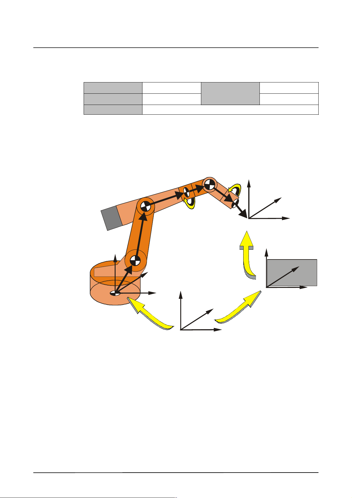
Offset and orientation of the robot relative to the world coordinate system.
Ceiling--mounted robots: Angle C is 180 degrees
Wall--mounted robots: Angle B is 90 degrees
The frame chain or vector chain of the robot arm (axes 1 to 6) without external axes is
illustrated in Fig. 2:
ue
min
max
-- --
-- --
A5
A4
A3
Z
$TOOL
Y
A6
X
$POS_ACT
Robot
Z
Z
Workpiece
A2
Y
Y
A1
$ROBROOT
X
Z
$BASE
Y
X
X
$WORLD
Fig. 2 Frame chain without external axes
The BASE coordinate system is used as the reference system to define the position of the
workpiece. The programming of the robot is done in the BASE coordinate system, which has
the WORLD coordinate system as its reference coordinate system.
When interpolating the motion path, the robot controller calculates, under normal
circumstances (stationary workpiece, tool mounted on the robot flange), the current position
($POS_ACT) in relation to the $BASE coordinate system.
Maschi nendaten 12.0400 en
13 of 91
Machine Data
Val
2.1.9 $ERSYSROOT
Offset and orientation with external axes
Data type -- --
Unit mm, degrees
Assignment FRAME {X, Y, Z, A, B, C}
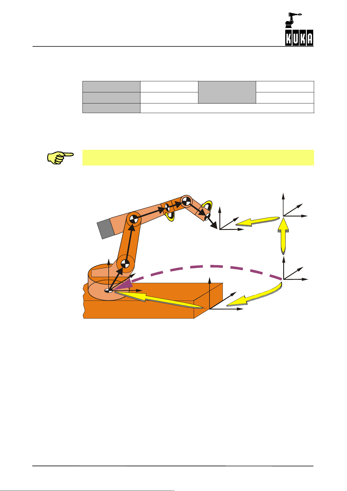
Offset and orientation of the robot relative to the world coordinate system.
Defines the offset between the root point of the external axis and the robot base flange.
Only valid if external axes are present (e.g. robot is mounted on a linear unit).
If $ERSYSROOT is valid, $ROBROOT is ignored.
The frame chain of a robot arm and a linear unit (KL) with mathematical coupling is illustrated
below (Fig. 3).
A5
A4
A3
Z
$TOOL
A6
Robot
ue
min
max
$POS_ACT
Y
X
-- --
-- --
Z
Y
X
$BASE
Z
A2
Y
A1
($ROBROOT)
Linear traversing unit
The external ROBROOT kinematic system lies in the offset from “$WORLD” to
“$ROBROOT”. With every motion of the ROBROOT kinematic system, the position in space
of the robot changes. As allowance must always be made for this external axis when
calculating the position, this external kinematic system is always situated in the offset from
“$WORLD” to “$ROBROOT”.
The external coupling is always switched on and cannot be switched off. As in the case of
the external BASE kinematic system, there is no constant ROBROOT value. The contents
of the machine datum “$ROBROOT” are ignored. The current value can be read from the
main run variable “$ROBROOT_C”.
X
#ERSYS
Fig. 3 Frame chain with linear unit
$ROBROOT_C(t)
Z
Y
X
$ERSYSROOT
Z
Y
$WORLD
X
Maschi nendaten 12.0400 en
14 of 91

2.1.10 $RAT_MOT_AX[ ]
Val
Motor/axis gear ratio
2 The file $MACHINE.DAT (continued)
Data type frame
min
15
ue
Unit []
Assignment
[1] axis 1 ... [6] axis 6
[7] external axis 1 ... [12] external axis 6
max
-- --
In order to calculate the resolution, the gear ratio of the motor to the axis must be specified
for each axis. This information is entered as a fraction. The direction of rotation of the axis
can be changed by means of a negative sign in the numerator N.
$RAT_MOT_AX[i]={N x,D y}
i = axis number
x = value of numerator N (i.e. motor)
y = value of denominator D (i.e. axis)
Unit for linear axes: [Number of motor revolutions per 1000 mm travel]
Example 1
Rotational axis with gear unit:
Every 10th motor revolution, the axis turns through 1 revolutions.
$RAT_MOT_AX[i]={N 100,D 1}
Example 2
Linear axis:
I
= complete reduction ratio of the gear unit
compl
I
= reduction ratio of the gear box
box
D = reference diameter of the gear [unit = m]
I
compl
=
(
π ⋅ D
⋅ i
box
)
1
The gear ration should be at least {N 15,D 1}.
Maschi nendaten 12.0400 en
15 of 91

Machine Data
Val
Val
2.1.11 $RAT_MOT_ENC[ ]
Motor/encoder ratio
Data type frame
Unit []
Assignment
In order to calculate the resolution, the ratio of the motor to the encoder must be specified
for each axis. For cyclical absolute encoders, the number of cyclical absolute periods per
revolution is defined.
$RAT_MOT_ENC[i]={N x,D y}
i = axis number
x = value of numerator N (i.e. motor)
y = value of denominator D (i.e. axis)
Example 1
Robot with a 6--pole resolver: (3 absolute ranges, each 120 degrees)
$RAT_MOT_ENC[i]={N 1,D 3}
2.1.12 $DSECHANNEL[ ]
Axis assignment on the DSE
ue
[1] axis 1 ... [6] axis 6
[7] external axis 1 ... [12] external axis 6
min
max
-- --
-- --
Data type int
min
0
ue
Unit []
Assignment
[1] axis 1 ... [6] axis 6
[7] external axis 1 ... [12] external axis 6
max
18
Until now, this variable has determined which of the 8 DSE channels is assigned to an axis
(An) (and thus also which slot on the RDC). With the new definition of this variable, a control
loop (“loop”) on the DSE is now assigned to an axis (An). There are 8 control loops
(corresponding to 8 channels) on the DSE.
In the case of master/slave configurations, the number of the master control loop is entered.
With the default robot configuration, axes 1--6 are consecutively assigned to channels 1--6
(and thus control loops 1--6) respectively. With standard configurations the meaning of this
variable thus remains unchanged.
The number of motor pole pairs should be the same as, or a multiple of, the number of
resolver pole pairs.
Maschi nendaten 12.0400 en
16 of 91

2 The file $MACHINE.DAT (continued)
Valid values for $DSECHANNEL are:
Loop
0 Channel not used
1--8 (1--9) 8 control loops on DSE no. 1 (+spare channel 9)
10--17 (10--18) 8 control loops on DSE no. 2 (+spare channel 18)
Each control loop number may be specified only once.
This entry defines which DSE channel is to be used by the axis.
There are eight channels available on the first DSE. With a standard robot, channels 7 and
8 can thus be used for external axes.
The RDC inputs are also defined using “$DSECHANNEL”.
For unused axes, $DSECHANNEL[ ] = 0 must be entered.
$DSECHANNEL[i]=K
i = robot axis
K = DSE channel and RDC channel
Example
Axes 1 and 2 occupy DSE channels 1 and 2 and slots X1 and X2 on the RDC card;
axis 7 occupies DSE channel 3 and slot 3 on the RDC card:
$DSECHANNEL[1]=1
$DSECHANNEL[2]=2
$DSECHANNEL[3]=0
$DSECHANNEL[4]=0
$DSECHANNEL[5]=0
$DSECHANNEL[6]=0
$DSECHANNEL[7]=3
Maschi nendaten 12.0400 en
17 of 91

Machine Data
Val
2.1.13 $PMCHANNEL[ ]
Selection of the KPS
Data type int
min
20
ue
Unit []
Assignment
[1] axis 1 ... [6] axis 6
[7] external axis 1 ... [12] external axis 6
max
34
$PMCHANNEL[An]
This variable defines which KPS is used to drive the axis (An). The meaning remains
unchanged.
In the case of master/slave configurations with several KPSs for master and slave axes, only
the assignment of the master axis is entered here. For slave axes, the KPS is defined using
the variable $SLAVE_LOOP_PMCHANNEL (see below).
Assignment of the axes to the drive interfaces of a single KPS.
The following applies for robot axes 1 to 6:
$PMCHANNEL[1]=20
$PMCHANNEL[2]=20
$PMCHANNEL[3]=20
$PMCHANNEL[4]=20
$PMCHANNEL[5]=20
$PMCHANNEL[6]=20
The following applies for external axes 7 and 8:
$PMCHANNEL[7]=21
$PMCHANNEL[8]=21
Example
Axis 4 uses the first channel of the second KPS.
PMCHANNEL[4]=22
The following applies for the first DSE--IBS:
$PM_CHANNEL[]=20 1st KPS
$PM_CHANNEL[]=22 2nd KPS
$PM_CHANNEL[]=24 3rd KPS
$PM_CHANNEL[]=26 4th KPS
Maschi nendaten 12.0400 en
18 of 91

The following applies for the second DSE--IBS:
Val
Val
$PM_CHANNEL[]=28 1st KPS
$PM_CHANNEL[]=30 2nd KPS
$PM_CHANNEL[]=32 3rd KPS
$PM_CHANNEL[]=34 4th KPS
$PM_CHANNEL is also used to define the braking channel (2 per KPS) assigned to the axis
brake. Odd numbers indicate that the second braking channel of the KPS is used.
Example
Axis 5 is assigned to the first braking channel of the first KPS of the first DSE.
$PM_CHANNEL[5]=20
Axis 7 is assigned to the second braking channel of the first KPS of the first DSE.
$PM_CHANNEL[7]=21
This machine datum has been expanded for external drive boxes. The meaning of the
existing contents remains unchanged. A “1” before the entry signifies that the axis module
concerned has an SBM (Single Brake Module).
2.1.14 $LOOP_LG_PTP[ ]
2 The file $MACHINE.DAT (continued)
Position controller gain
Data type real
Unit -- --
Assignment -- --
Defines the position controller gain of the control loop.
The value applies to PTP and CP motion.
It is only required for the control loop of a position--controlled slave (“Slave Pos”).
2.1.15 $LOOP_G_VEL_PTP[ ]
Speed controller gain
Data type Real
Unit -- --
Assignment -- --
Defines the proportional gain of the speed controller.
ue
ue
min
max
min
max
-- --
-- --
-- --
-- --
The value applies to PTP and CP motion.
It is only required for the control loop of a position--controlled slave (“Slave Pos”).
Maschi nendaten 12.0400 en
19 of 91
Machine Data
Val
Val
Val
2.1.16 $LOOP_I_VEL_PTP[ ]
Integral component of the speed controller
Data type real
Unit -- --
Assignment -- --
Defines the integral factor of the speed controller.
The value applies to PTP and CP motion.
It is only required for the control loop of a position--controlled slave (“Slave Pos”).
2.1.17 $LOOP_DIRECTION[ ]
Direction specification for slave axes
Data type int
Unit -- --
Assignment -- --
Specifies the direction in which the slave moves relative to the master.
Description of the valid values:
Control loop of a position--controlled slave (“Slave Pos”):
ue
ue
min
max
min
max
-- --
-- --
-- --
-- --
1 = Same direction as master
--1 = Opposite direction to that of master
Control loop of a torque--controlled slave (“Slave Torq”):
1 = Same torque (or command current) as master
--1 = Opposite torque (or command current) to that of master
2.1.18 $SLAVE_LOOP_FOL_CRITICAL[ ]
Percentage value for configuration of a max. deviation limit
Data type int
Unit %
Assignment -- --
Shut--off threshold with loss of mastering
If the following error exceeds the threshold value, PATH--MAINTAINING BRAKING is
triggered.
The percentage value refers to $SLAVE_LOOP_FOL_ALARM.
The value must be >100, otherwise it is automatically set to 120.
ue
min
max
101
-- --
Maschi nendaten 12.0400 en
20 of 91

2.1.19 $SLAVE_LOOP_FOL_ALARM[ ]
Val
Val
Val
Val
Deviation limit between master and slave
2 The file $MACHINE.DAT (continued)
Data type real
Unit degrees, mm
Assignment -- --
Shut--off threshold
If the following error exceeds the threshold value, PATH--MAINTAINING BRAKING is
triggered.
2.1.20 $SLAVE_LOOP_SPEED_ALARM[ ]
Max. speed deviation for torque--controlled slave drives
Data type real
Unit rpm
Assignment -- --
Shut--off threshold
If the actual speed exceeds the threshold value, PATH--MAINTAINING BRAKING is
triggered. The value is specified in rpm.
2.1.21 $SLAVE_LOOP_PMCHANNEL[Ln]
Definition of the KPS module for slave control loops
ue
ue
min
max
min
max
-- --
-- --
-- --
-- --
Data type int
Unit []
Assignment -- --
$SLAVE_LOOP_PMCHANNEL[Ln]=y defines the KPS module connected to a slave control
loop. In the case of master loops, the value 0 must be entered as the assignment for these
control loops is already defined using $PMCHANNEL[An] (see above) and must not be taken
into consideration here.
2.1.22 $LOOP_TYPE[Ln]
Selection of the control loop type
Data type int
Unit []
Assignment -- --
$LOOP_TYPE[Ln]=y
ue
ue
min
max
min
max
--
-- --
1
4
Maschi nendaten 12.0400 en
21 of 91

Machine Data
Val
Val
This variable specifies the control loop type (Ln). Control loop type 4, for example, indicates
a control loop with 2 KSDs connected in parallel to a single motor with a double winding. The
main winding is commutated by a master (type 1), and the parallel winding by a slave (type 4).
The following values are possible:
y
1 Master control loop
2 Control loop of a position--controlled slave (“Slave Pos”)
3 Control loop of a torque--controlled slave (“Slave Torq”)
4 Control loop for parallel winding with 2 KSDs connected in parallel to a single motor
6 Force control, servo gun force control
In the case of 2 KSDs connected in parallel to a single motor, it is not possible to connect
the resolver of the motor to a CAN bus.
2.1.23 $LOOP_TYPE_ATTRIBUTE[ ]
Additional characteristics of the control loop
Data type int
Unit []
Assignment -- --
Bit array!
Required for certain Loop_types (currently only $Loop_type[Ln]=5) for the detailed
definition of linked characteristics.
Default value = 0
This machine datum is used exclusively for KUKA--internal development purposes.
2.1.24 $MASTER_LOOP[Ln]
Selection of the higher--level master control loop
Data type int
Unit []
Assignment -- --
$MASTER_LOOP[Ln]=y
In the case of slave control loops, this variable indicates the number of the higher--level
master control loop. The permissible combinations are described in the documentation about
the master/slave functions.
ue
ue
min
max
min
max
1
18
1
18
Maschi nendaten 12.0400 en
22 of 91

Valid values for $MASTER_LOOP are:
Val
Val
y
1--8 (1--9) Control loop number of the master (only DSE no. 1)
10--17 (10--18) Control loop number of the master (only DSE no. 2)
Master and slave loops cannot be distributed over two DSEs.
2.1.25 $SLAVE_TORQUE_RATIO[ ]
Torque--controlled slave: ratio between command torque and slave/master
2 The file $MACHINE.DAT (continued)
Data type real
Unit []
Assignment -- --
This variable specifies the torque (or command current!) for the slave relative to the master.
It is only required for the control loop of a torque--controlled slave (“Slave Torq”).
2.1.26 $NINPUT_SENSORTYPE[Ln]
Sensor type for the speed input
Data type int
Unit []
Assignment -- --
$NINPUT_SENSORTYPE[Ln]=y defines the sensor type for the speed input of the DSE
control loop (Ln). This describes the hardware connection.
Valid values for $NINPUT_SENSORTYPE are:
y
1 Sensor (resolver) connected to RDC
ue
ue
min
max
min
max
1
5
1
5
2 Sensor with external resolver box connected via CAN--KSD and servo bus
3 Incremental encoder connected via CAN--KSD and servo bus
4 Servo bus encoder with IBS K3 protocol (multiple/single incremental encoder)
5 Servo bus encoder with IBS K2 protocol (multiple/single incremental encoder)
Maschi nendaten 12.0400 en
23 of 91

Machine Data
Val
Val
2.1.27 $NINPUT_SENSORCHANNEL[Ln]
Channel number of the speed input for the DSE loop
Data type int
Unit []
Assignment -- --
$NINPUT_SENSORCHANNEL[Ln]=y for RDC--commutated motors:
Defines the channel number (y) of the speed input for the DSE loop (Ln). Each channel
number may be specified only once. The $NINPUT_SENSORCHANNEL channel number
should be the same as the DSE channel number in order to avoid confusion during
configuration. A different assignment would be technically possible, however.
For CAN--RDC--commutated motors:
Defines the KSD--SBM in the servo bus ring from which the NINPUT information is received.
Other devices, such as the KPS, are not counted as KSD--SBMs.
This is necessary as the NINPUT and POSINPUT information of a control loop may come
from different KSDs.
2.1.28 $NINPUT_SUBCHANNEL[Ln]
Sub--channel for speed channel of a DSE control loop
Data type int
Unit []
Assignment -- --
ue
ue
min
max
min
max
-- --
-- --
1
4
$NINPUT_SUBCHANNEL[Ln]=y This variable can be used to define a “sub--channel” for
each speed channel of a DSE control loop (Ln). This can be used for a more detailed
definition, for example, if an encoder supplies different values on a single channel. The value
0 must be entered if this variable is not required.
RDC--commutated motors:
The SUBCHANNEL is not required; the value 0 must be entered.
CAN--RDC--commutated motors:
If the encoder is connected via external resolver box, CAN and servo bus (“sensor type 2”),
the resolver channel, i.e. the number of the slot on the external resolver box (“CAN--RDC”),
is set here. Only the slot on the CAN--RDC need be specified here, as the specification of
which CAN--RDC is connected to the motor is defined by the position in the servo bus. An
additional CAN--RDC must be connected after each KPS (see example 3).
Maschi nendaten 12.0400 en
24 of 91
Valid values for $NINPUT_SUBCHANNEL with “sensor type 2” are:
Val
Val
Val
y=1--4
y: resolver channel; 1: CAN master*
* The “CAN master” is responsible for synchronization of the resolver box with the servo bus.
A CAN master must be defined for each resolver box. It is not possible to connect more than
one CAN master to a single resolver box. The sequence of the information from the resolver
slots is by definition always identical to the sequence of the KSDs with CAN--RDC in the servo
bus!
Each CAN channel may be specified only once.
2.1.29 $POSINPUT_SENSORTYPE[Ln]
Position input of the DSE control loop
2 The file $MACHINE.DAT (continued)
Data type int
Unit []
Assignment -- --
$POSINPUT_SENSORTYPE[Ln]=y
Like $NINPUT_SENSORTYPE for the position input of the DSE control loop (Ln).
2.1.30 $POSINPUT_SENSORCHANNEL[Ln]
Position input of the DSE loop
Data type int
Unit []
Assignment -- --
$POSINPUT_SENSORCHANNEL[Ln]=y
Like $NINPUT_SENSORCHANNEL for the position input of the DSE control loop (Ln).
Additional laser sensor:
The SENSORCHANNEL defines the laser sensor in the servo bus ring from which the
position information is received.
2.1.31 $POSINPUT_SUBCHANNEL[Ln]
ue
ue
min
max
min
max
-- --
-- --
-- --
-- --
Position input of the DSE control loop
Data type int
min
-- --
ue
Unit []
max
-- --
Assignment -- --
$POSINPUT_SUBCHANNEL[Ln]=y
Like $NINPUT_SUBCHANNEL for the position input of the DSE control loop (Ln).
Maschi nendaten 12.0400 en
25 of 91
Machine Data
Val
Val
Val
2.1.32 $TORQINPUT_SENSORTYPE[Ln]
Force/torque input of the DSE control loop
Data type real
Unit []
Assignment -- --
$TORQINPUT_SENSORTYPE[Ln]=y
Like $NINPUT_SENSORTYPE for the force/torque input of the DSE control loop (Ln).
2.1.33 $LOOP_RAT_MOT_AX[ ]
Motor / drive gear ratio of the slave axis
Data type frame
Unit []
Assignment -- --
Gear ratio (motor:axis) of a slave control loop.
The ratio (motor : rotary encoder) of the slave must be the same as that of the master.
Only for slave drives.
Example
ue
ue
min
max
min
max
-- --
-- --
-- --
-- --
$LOOP_RAT_MOT_AX[2]={N 20,D 1}
2.1.34 $LOOP_RAT_EXTPOS_AX[ ]
Ratio of the sensor gear
Data type frame
Unit []
Assignment -- --
Gear ratio of the external position encoder of a control loop (possible for both master and
slave).
Example
$LOOP_RAT_EXTPOS_AX[1]={N --3,D 1}
ue
min
max
-- --
-- --
Maschi nendaten 12.0400 en
26 of 91

2.1.35 $MOTOR_POLE_NUMBER[ ]
Val
Val
Val
Number of pole pairs of the motor
2 The file $MACHINE.DAT (continued)
Data type int
Unit []
Assignment -- --
This machine datum is used exclusively for KUKA--internal development purposes.
Default value: 3
2.1.36 $SERVOFILE_CONFIG[ ]
Configuration file for motor/KSD combination
Data type char
Unit []
Assignment -- --
The servo file entered must be located in the R1/MADA directory.
For each permissible motor/KSD combination there is a special configuration file which must
be entered in the machine data:
ue
ue
min
max
min
max
-- --
-- --
-- --
-- --
Example
Axis 1 is driven by a motor of type B (S=Siemens) and controlled using a KSD1--32:
CHAR $SERVOFILE1[16]
$SERVOFILE1[]=“KSD_32_MB_S”
2.1.37 $SERVOFILEKPS1[ ]
Servo file KPS1 DSE1
Data type char
Unit []
Assignment -- --
For each KPS there is a configuration file which must be entered in the machine data:
ue
min
max
-- --
-- --
Maschi nendaten 12.0400 en
27 of 91

Machine Data
Val
Val
The servo file entered must be located in the R1/MADA directory.
Example
First KPS of type 600_20 on the first DSE:
2.1.38 $CURR_MAX[ ]
Maximum KSD current
$SERVOFILEKPS1[] = “KPS_600_20”
Data type real
Unit A
Assignment -- --
Maximum effective current at the KSD output.
KSD type
$CURR_MAX[ ] 64 48 32 16 8
Example
Axis 7 is controlled using a KSD1--48:
2.1.39 $CURR_CAL[ ]
$CURR_MAX[i]=K
i = axis number
K = max. KSD current (A
$CURR_MAX[7] = 48
rms
KSD
1--64
min
8
ue
max
64
)
KSD
1--48
KSD
1--32
KSD
1--16
KSD
1--08
KSD current calibration
Data type real
min
-- --
ue
Unit []
max
-- --
Assignment -- --
In the KR C2, $CURR_CAL[i] always has the value 1.
$CURR_CAL[i]=K
i = axis number
K = current factor
Maschi nendaten 12.0400 en
28 of 91

2.1.40 $CURR_LIM[i]
Val
Val
Current setpoint limit
2 The file $MACHINE.DAT (continued)
Data type int
min
1
ue
Unit %
max
100
Assignment Axis number
The current setpoint defines the maximum permissible motor current and thus also defines
the torque limit. This value is entered as a percentage of the maximum KSD current.
The following relationship exists between the machine data:
$CURR_LIM[i]= (max. motor current I
/ $CURR_MAX[i]) x 100
max
$CURR_LIM[i]=K
i = axis number
K = current limit
Example
For a motor of type E with a KSD1--08, the following applies:
$CURR_LIM[ ]= (7.3 / 8) x 100 = 91
If the motor current is set too high, this can result in damage to the gear unit
or demagnetization of the permanent magnets in the motors.
2.1.41 $CURR_MON[i]
Permissible standstill current of the motor
Data type real
Unit A
Assignment
Specification of the permissible standstill current of the motor for axis i.
If the value is set too high, this can cause the motor cable or the motor itself
to overheat.
ue
[1] axis 1 ... [6] axis 6
[7] external axis 1 ... [12] external axis 6
min
max
-- --
-- --
Maschi nendaten 12.0400 en
29 of 91
Machine Data
Val
Val
Val
2.1.42 $KPS_CURR_MAX
Maximum current of the KPS over 1 s (KR C2)
Data type real
Unit A
Assignment
2.1.43 $KPS_CURR_RATED
Maximum rated current of a KPS over 60 s (KR C2)
Data type real
Unit A
Assignment
2.1.44 $CURR_COM_EX[ ]
Current limit of the external axes for jogging
Data type real
Unit %
Assignment
ue
[1] axis 1 ... [6] axis 6
[7] external axis 1 ... [12] external axis 6
ue
[1] axis 1 ... [6] axis 6
[7] external axis 1 ... [12] external axis 6
ue
[1] axis 1 ... [6] axis 6
[7] external axis 1 ... [12] external axis 6
min
max
min
max
min
max
-- --
-- --
-- --
-- --
-- --
-- --
Definition of the max. limit for the torque and motor current for jogging the external axes. This
value is entered as a percentage of the maximum KSD current.
It is used, for example, for machine protection when jogging a position--controlled electric
motor--driven weld gun. On closing the gun, the current would go to the command current
limit ($CURR_LIM) and destroy the gun.
The value of $CURR_COM_EX[1] is written to the variable for torque mode when jog key
E1 is pressed.
Example
$CURR_COM_EX[1]=50
$CURR_RED[7.1]=50
$CURR_RED[7.2]=50
Maschi nendaten 12.0400 en
30 of 91

2.1.45 $KT_MOT[ ]
Val
Val
Val
KT factor of the motors
2 The file $MACHINE.DAT (continued)
Data type real
Unit -- --
Assignment
This entry describes the motor characteristic in terms of the ratio between the torque and
the rated current at the nominal velocity.
Default value dependent on motor type.
2.1.46 $KT0_MOT[ ]
KT0 factor of the motors
Data type real
Unit -- --
Assignment
This entry describes the motor characteristic in terms of the ratio between the torque and
the rated current at standstill.
Default value dependent on motor type.
2.1.47 $RAISE_TIME[ ]
ue
[1] axis 1 ... [6] axis 6
[7] external axis 1 ... [12] external axis 6
ue
[1] axis 1 ... [6] axis 6
[7] external axis 1 ... [12] external axis 6
min
max
min
max
-- --
-- --
-- --
-- --
Axis acceleration time
Data type real
min
-- --
ue
Unit ms
Assignment
[1] axis 1 ... [6] axis 6
[7] external axis 1 ... [12] external axis 6
max
-- --
$RAISE_TIME + $FILTER/2 is the time in ms in which the axis can be accelerated to its rated
speed ($VEL_AXIS_MA). ($FILTER is usually $DEF_FLT_PTP)
If the value is set too low, a corresponding error message is generated. This means that the
ramp is too steep and that the current limit is thus exceeded. This value can be determined
exactly using the oscilloscope.
Only used with non--KUKA kinematic systems with deactivated acceleration adaptation
($ADAP_ACC=#NONE) and deactivated higher motion profile ($OPT_MOVE=#NONE).
With KUKA standard robots, the accelerations are calculated according to the reach, the
specified load and the mass inertia. In this case, the times are only used for monitoring the
command acceleration.
Maschi nendaten 12.0400 en
31 of 91

Machine Data
Val
Val
The corresponding axis must not be allowed to go into current limitation during
measurement and should not exceed 90% of Imax.
Normal values = 300 to 1000 ms
Default value = 500 ms
2.1.48 $RAISE_T_MOT[ ]
Motor acceleration time
Data type real
Unit ms
Assignment
The entry “$RAISE_T_MOT[ ]” defines the time taken for the motor to accelerate to the rated
speed without an axis. These data are incorporated in the calculation of the dynamic model
and monitored.
Default value = 5.0
Example
$RAISE_T_MOT[7]=5.0
$RAISE_T_MOT[8]=5.0
The motor speed must be lower than the maximum frequency (266 Hz) of the RDC.
2.1.49 $VEL_AXIS_MA[ ]
Rated motor speed
ue
[1] axis 1 ... [6] axis 6
[7] external axis 1 ... [12] external axis 6
min
max
-- --
-- --
32 of 91
Data type real
min
-- --
ue
Unit rpm
Assignment
[1] axis 1 ... [6] axis 6
[7] external axis 1 ... [12] external axis 6
max
-- --
The rated speed of the axis motor is defined here. This maximum speed is reached with
override set to 100%. It is possible to reduce the axis traversing velocity.
Example
The drive motor of axis 7 is to have a rated speed of 1500 rpm:
$VEL_AXIS_MA[7]=1500.0
Maschi nendaten 12.0400 en

2.1.50 $VEL_CPT1_MA
Val
Val
Val
Reduction factor for CP motions in T1
2 The file $MACHINE.DAT (continued)
Data type int
Unit -- --
Assignment
2.1.51 $VEL_DSE_MA[ ]
Axis--specific velocity monitoring limits
Data type int
Unit -- --
Assignment
Actual speed monitoring on the DSE.
v_ist_max = v_soll_max*$VEL_DSE_MA/100
v_soll_max is the currently valid command velocity limit
2.1.52 $AXIS_RESO[ ]
Resolution of the measuring system
Data type int
Unit increments
Assignment
ue
[1] axis 1 ... [6] axis 6
[7] external axis 1 ... [12] external axis 6
ue
[1] axis 1 ... [6] axis 6
[7] external axis 1 ... [12] external axis 6
ue
[1] axis 1 ... [6] axis 6
[7] external axis 1 ... [12] external axis 6
min
max
min
max
min
max
-- --
-- --
-- --
-- --
-- --
-- --
This entry defines the resolution (pulse count) of an encoder:
G per encoder revolution (for incremental and absolute encoders).
G per absolute cyclic range (e.g. for multi--pole resolvers).
Default value:
G 4096 for KR C2
Example
The default value 4096 is entered for axis 7:
$AXIS_RESO[7]=4096
Maschi nendaten 12.0400 en
33 of 91
Machine Data
Val
Val
2.1.53 $RED_VEL_AXC[ ]
Reduction factor for axial velocity (HOV)
Data type int
Unit %
Assignment
Reduction factor for axial velocities during axis--specific jogging and in command mode (PTP
motion) relative to the rated motor speed “$VEL_AXIS_MA”. This means a reduction in
velocity to the 250 mm/s predefined in HOV.
Default value = 10
Example
$RED_VEL_AXC[7]=10
$RED_VEL_AXC[8]=10
2.1.54 $RED_ACC_AXC[ ]
Reduction factor for axial acceleration (HOV)
Data type int
Unit %
Assignment
ue
[1] axis 1 ... [6] axis 6
[7] external axis 1 ... [12] external axis 6
ue
[1] axis 1 ... [6] axis 6
[7] external axis 1 ... [12] external axis 6
min
max
min
max
-- --
-- --
-- --
-- --
“$RED_ACC_AXC[ ]” is the reduction factor for axial acceleration during axis--specific
jogging and in command mode (PTP motion) relative to the maximum axial acceleration
= $VEL_AXIS_MA[ ]/$RAISE_TIME[ ].
If the values are set too high, the axis will vibrate (jerky start to motions).
Default value = 20
Example
$RED_ACC_AXC[7]=20
$RED_ACC_AXC[8]=20
Maschi nendaten 12.0400 en
34 of 91

2.1.55 $RED_ACC_DYN
Val
Val
Val
Val
Val
Reduzierfaktor für Beschleunigung
2 The file $MACHINE.DAT (continued)
Data type int
Unit %
Assignment -- --
This factor can generally be used to reduce all accelerations to the specified value.
2.1.56 $RED_VEL_CPC
Reduction factor for CP and orientation velocity
Data type int
Unit %
Assignment -- --
Reduction factor for CP and orientation velocity in Cartesian jogging and command mode
(CP).
2.1.57 $RED_ACC_CPC
Reduction factor for CP and orientation acceleration
Data type int
Unit %
Assignment -- --
ue
ue
ue
min
max
min
max
min
max
-- --
-- --
-- --
-- --
-- --
-- --
Reduction factor for CP and orientation acceleration in Cartesian jogging and command
mode (CP).
2.1.58 $VEL_CP_T1
Maximum CP velocity in Test1 mode
Data type real
Unit m/s
Assignment -- --
2.1.59 $VEL_CP_COM
Reduction factor for flange velocity
Data type real
Unit m/s
Assignment -- --
Reduction factor for the flange velocity in tool reorientation motions.
ue
ue
min
max
min
max
-- --
0,25
-- --
-- --
Maschi nendaten 12.0400 en
35 of 91

Machine Data
Val
Val
Val
2.1.60 $RED_JUS_UEB
Reduction factor for sensor location run
Data type real
Unit %
Assignment -- --
This machine datum is used exclusively for KUKA--internal development purposes.
2.1.61 $RED_ACC_OV[ ]
Axial reduction of acceleration for override
Data type int
Unit %
Assignment
This setting allows you to reduce the accelerations caused by changes to the override setting
in axial motions.
This entry is fixed
Default value = 100
Example
ue
ue
[1] axis 1 ... [6] axis 6
[7] external axis 1 ... [12] external axis 6
min
max
min
max
-- --
-- --
100
100
$RED_ACC_OV[7]=100
$RED_ACC_OV[8]=100
2.1.62 $ACC_CAR_TOOL
Cartesian acceleration monitoring (relative to the flange)
Data type frame
Unit -- --
Assignment FRAME {X, Y, Z, A, B, C}
If the effective accelerations at a specific point on a tool that is mounted on the flange are
to be calculated cyclically and monitored against a maximum value, the machine datum
defines this point.
ue
min
max
-- --
-- --
Maschi nendaten 12.0400 en
36 of 91

2.1.63 $ACC_CAR_LIMIT
Val
Val
Val
Cartesian acceleration monitoring
2 The file $MACHINE.DAT (continued)
Data type frame
Unit m/s
Assignment FRAME {X, Y, Z, A, B, C}
The frame variable $ACC_CAR_LIMIT can be used to set a value for the maximum
permissible acceleration for the components X, Y and Z.
As soon as the current acceleration in one component exceeds one of these values the robot
is stopped by means of ramp--down braking (as when the Stop key is pressed) and the error
message “Maximum Cartesian acceleration exceeded” is displayed. This message is an
acknowledgement message.
The default value for all components of $ACC_CAR_LIMIT is zero. At present, only the
components ABS, X, Y and Z are used.
The components A, B and C are not evaluated.
The stop reaction is only triggered if the machine datum $ACC_CAR_STOP is set to
TRUE. If the value is FALSE, no stop reaction takes place.
2.1.64 $ACC_CAR_ACT
For future expandability to rotational acceleration
Data type frame
Unit -- --
Assignment FRAME {X, Y, Z, A, B, C}
min
2
ue
max
min
-- --
-- --
-- --
ue
max
-- --
This machine datum is used exclusively for KUKA--internal development purposes.
2.1.65 $ACC_CAR_STOP
Cartesian acceleration monitoring
Data type bool
Unit -- --
Assignment -- --
This machine datum can be used to activate/deactivate the stop reaction triggered when the
permissible limits specified in $ACC_CAR_LIMIT are exceeded.
The current acceleration is always calculated and $ACC_CAR_MAX is always updated
irrespective of $ACC_CAR_STOP .
ue
min
max
-- --
-- --
Maschi nendaten 12.0400 en
37 of 91

Machine Data
Val
Val
2.1.66 $RED_ACC_EMX[ ]
Reduction factor for path--maintaining Emergency Stop ramp
Data type int
Unit %
Assignment
In the case of a normal Emergency Stop, the maximum current should not be exceeded,
otherwise the robot is no longer stopped on the path. The exact value can be determined
using the oscilloscope.
Path--maintaining E--Stop ramp [ms] = $RAISE_TIME[ms]/$RED_ACC_EMX[%]*100[%]
The corresponding axis should not be allowed to go into current limitation.
Default value = 100
Example
$RED_ACC_EMX[7]=100
$RED_ACC_EMX[8]=100
2.1.67 $WARMUP_RED_VEL
ue
[1] axis 1 ... [6] axis 6
[7] external axis 1 ... [12] external axis 6
min
max
-- --
-- --
Warm--up functionality
Data type bool
Unit -- --
Assignment -- --
Example
Warm--up functionality activated:
$WARMUP_RED_VEL=TRUE
ue
min
max
-- --
-- --
Maschi nendaten 12.0400 en
38 of 91

2.1.68 $WARMUP_TIME
Val
Val
Val
Val
Val
Warm--up time of the gears
2 The file $MACHINE.DAT (continued)
Data type real
Unit min
Assignment -- --
If the gear units are very cold, the increased friction means that there is insufficient motor
torque available for motion with high acceleration and speed.
This function makes it possible for the robot not to shut down on reaching the motor limits
during the time defined in WARMUP_TIME, but merely to move more slowly.
As long as the robot is considered cold, the motor currents are monitored for all PTP motions.
As soon as the current for one axis is greater than the maximum current specified in
$WARMUP_CURR_LIMIT , an internal override is multiplied by the factor
$WARMUP_MIN_FAC in order to reduce the motor currents.
This internal override is subsequently reset to 100% in several steps
($WARMUP_SLEW_RATE).
2.1.69 $COOLDOWN_TIME
Cool--down time
Data type real
Unit min
Assignment -- --
ue
ue
min
max
min
max
-- --
-- --
-- --
-- --
2.1.70 $WARMUP_CURR_LIMIT
Monitoring value of the max. motor current
Data type int
Unit %
Assignment -- --
2.1.71 $WARMUP_MIN_FAC
Min. factor applied to the den override
Data type int
Unit %
Assignment -- --
2.1.72 $WARMUP_SLEW_RATE
Factor by which the internal override is increased
Data type real
Unit %/s
Assignment -- --
ue
ue
ue
min
max
min
max
min
max
-- --
-- --
-- --
-- --
-- --
-- --
Maschi nendaten 12.0400 en
39 of 91

Machine Data
Val
Val
2.1.73 $ST_TOL_VEL[ ]
Velocity tolerance for standstill detection
Data type real
ue
Unit rpm
Assignment
[1] axis 1 ... [6] axis 6
[7] external axis 1 ... [12] external axis 6
Velocity tolerance for standstill detection. This entry is fixed.
Default value = 15.0
v
+$ST_TO_VEL
--$ST_TO_VEL
t1 < $ST_TOL_TIME
t2 < $ST_TOL_TIME
min
max
Axis
stopped
15.0
15.0
t
2.1.74 $ST_TOL_TIME
Detection time
Data type int
Unit ms
Assignment
See Fig. 4.
Fig. 4 Standstill detection
ue
[1] axis 1 ... [6] axis 6
[7] external axis 1 ... [12] external axis 6
min
max
15.0
15.0
Maschi nendaten 12.0400 en
40 of 91

2.1.75 $BOUNCE_TIME
Val
Val
Val
Bounce time for EMT signals
2 The file $MACHINE.DAT (continued)
Data type int
Unit ms
Assignment -- --
The signal is only accepted if it remains stable for the whole period defined in
$BOUNCE_TIME.
2.1.76 $VEL_AX_JUS[ ]
Velocity for EMT mastering
Data type real
Unit mm/s, degrees/s
Assignment
This entry defines the velocity at which a particular axis moves during EMT mastering. The
user can thus set the velocity in such a way that the EMT can detect the reference notch
reliably. The vertical velocity required by the EMT should be ±250
Default value = 0.1
2.1.77 $SEN_DEL[ ]
Distance traveled by EMT during signal propagation delay
ue
ue
[1] axis 1 ... [6] axis 6
[7] external axis 1 ... [12] external axis 6
min
max
min
max
-- --
-- --
-- --
-- --
mm/s.
Data type int
min
-- --
ue
Unit increments
Assignment
[1] axis 1 ... [6] axis 6
[7] external axis 1 ... [12] external axis 6
max
-- --
“$SEN_DEL[ ]” is the distance covered between detection of the mastering notch and output
of the signal to the controller, i.e. the distance covered during the signal propagation delay.
Entry for the difference between EMT and dial mastering for the “same” mastering position.
Default value = 0
Maschi nendaten 12.0400 en
41 of 91

Machine Data
Val
Val
Val
2.1.78 $L_EMT_MAX[ ]
Maximum length of EMT mastering travel
Data type real
Unit degrees, mm
Assignment
This is the maximum length of the EMT mastering path. If this path is exceeded, a
corresponding message is generated and the mastering process is aborted.
Formula:
2.1.79 $G_VEL_CAL
Velocity factor for speed controller gain
Data type real
Unit -- --
Assignment
This machine datum is used exclusively for KUKA--internal development purposes.
[1] axis 1 ... [6] axis 6
[7] external axis 1 ... [12] external axis 6
$L_EMT_MAX = 8 / 5 * EMT_path
[1] axis 1 ... [6] axis 6
[7] external axis 1 ... [12] external axis 6
ue
ue
min
max
min
max
-- --
-- --
-- --
-- --
2.1.80 $LG_PTP[ ]
Loop gain PTP
Data type real
Unit 1/ms
Assignment
“$LG_PTP[ ]” is used to set the loop gain of the position control loop for PTP motions. This
influences the motion characteristics of the axis.
If the control value is set too high, the command value is reached quickly resulting in “hard
control”. This causes the axis to “pulse”.
[1] axis 1 ... [6] axis 6
[7] external axis 1 ... [12] external axis 6
Default value = 0.3
ue
min
max
-- --
-- --
Maschi nendaten 12.0400 en
42 of 91

2.1.81 $LG_CP[ ]
Val
Val
Val
Loop gain for CP motion
2 The file $MACHINE.DAT (continued)
“$LG_CP[ ]” is used to define the loop gain of the position controller for CP motion. In order
to achieve optimal CP motion, the value of the robot motors should be entered here.
2.1.82 $TC_SYM
Time--constant for symmetry of the axes
In order to achieve optimal CP motion, the value of the equivalent time constant of the
slowest speed control loop should be entered here.
Default value = 0.1
Data type real
Unit 1/ms
Assignment
[1] axis 1 ... [6] axis 6
[7] external axis 1 ... [12] external axis 6
All axes have the same value.
Data type real
Unit -- --
Assignment -- --
ue
ue
min
max
min
max
-- --
-- --
-- --
-- --
2.1.83 $DECEL_MB[ ]
Braking ramp for dynamic braking
Data type real
Unit ms
Assignment
In the event of dynamic braking being triggered by a fault situation, it is possible to set a ramp
for the command speed using the entry “$DECEL_MB[ ]”. This prevents the command value
from falling too quickly and causing the current controller to go into limitation, which in turn
would prevent the robot from being braked in a controlled manner.
$DECEL_MB[] =
[1] axis 1 ... [6] axis 6
[7] external axis 1 ... [12] external axis 6
$RAISE_TIME[]
$RED_ACC_EMX[]
⋅ 100 but min. 180 ms
ue
min
max
-- --
-- --
Maschi nendaten 12.0400 en
43 of 91
Machine Data
Val
Val
Val
2.1.84 $G_COE_CUR
Proportional gain of the current controller
Data type int
Unit -- --
Assignment
This machine datum is only relevant for the KR C1 controller.
2.1.85 $G_VEL_PTP[ ]
Proportional gain of the speed controller for PTP motion
Data type real
Unit []
Assignment
The setting of the proportional gain of the speed controller for PTP motion is made in
“$G_VEL_PTP[ ]”.
The P component can be used to set the strength of the reaction of the controller output to
a deviation from the command value. Generally, the P component should be as high as
possible. However, if the P component is too high, this can render the control loop unstable;
this results in poor positioning or causes the drive to buzz loudly.
ue
[1] axis 1 ... [6] axis 6
[7] external axis 1 ... [12] external axis 6
ue
[1] axis 1 ... [6] axis 6
[7] external axis 1 ... [12] external axis 6
min
max
min
max
-- --
-- --
-- --
-- --
The value depends on the motor type.
2.1.86 $G_VEL_CP[ ]
Proportional gain of the speed controller for CP motion
Data type real
Unit []
Assignment
The setting of the proportional gain of the speed controller for CP motion is made in
“$G_VEL_CP[ ]”.
The P component can be used to set the strength of the reaction of the controller output to
a deviation from the command value. Generally, the P component should be as high as
possible. However, if the P component is too high, this can render the control loop unstable;
this results in poor positioning or causes the drive to buzz loudly.
The value depends on the motor type.
ue
[1] axis 1 ... [6] axis 6
[7] external axis 1 ... [12] external axis 6
min
max
-- --
-- --
Maschi nendaten 12.0400 en
44 of 91

2.1.87 $I_VEL_PTP[ ]
Val
Val
I factor of the speed controller for PTP motions
2 The file $MACHINE.DAT (continued)
Data type real
Unit []
Assignment
“$I_VEL_PTP[1]” is the integral--action factor of the speed controller for PTP motion.
The I component $I_VEL_PTP[ ] can be used to set the build--up speed of the controller
output in the event of a deviation from the command value. Generally, the I component
should be as small as possible, resulting in a fast rise. However, if the I component is too
small, this can render the control loop unstable; this results in poor positioning or causes the
drive to buzz loudly .
If the I factor of the controller is set too low, this cause vibrations.
Guide values: = 90 for small external motors
2.1.88 $I_VEL_CP[ ]
I factor of the speed controller for CP motion
ue
[1] axis 1 ... [6] axis 6
[7] external axis 1 ... [12] external axis 6
(typesC0,C,CS,D,E)
= 200 .. 500 for large external motors
(typesA01,A0,A,B,G1,I,I1,H,HS)
min
max
-- --
-- --
Data type real
min
-- --
ue
Unit []
Assignment
[1] axis 1 ... [6] axis 6
[7] external axis 1 ... [12] external axis 6
max
-- --
“$I_VEL_CP[ ]” is the integral--action factor of the speed controller for CP motion.
The I component $I_VEL_CP[ ] can be used to set the build--up speed of the controller output
in the event of a deviation from the command value. Generally, the I component should be
as small as possible, resulting in a fast rise. However, if the I component is too small, this
can render the control loop unstable; this results in poor positioning or causes the drive to
buzz loudly.
If the I factor of the controller is set too low, this cause vibrations.
Guide values: = 90 for small external motors (types C, D, E)
= 200 .. 500 for large external motors (types B, A, A0)
Maschi nendaten 12.0400 en
45 of 91

Machine Data
Val
Val
Val
2.1.89 $VEL_FILT[ ]
Tacho filter
Data type real
Unit ms
Assignment
“$VEL_FILT[ ]” sets the time constant for the current speed filter.
This entry is fixed.
2.1.90 $TM_CON_VEL
Minimum constant travel phase
Data type int
Unit ms
Assignment -- --
The minimum constant travel phase is used to avoid sudden loading of the robot arm. Such
loading is caused by abrupt changes between acceleration and braking with short distances
between points.
[1] axis 1 ... [6] axis 6
[7] external axis 1 ... [12] external axis 6
Default value = 2.5
v
min
ue
max
min
ue
max
2.5
2.5
-- --
-- --
$TM_CON_VEL=0
2.1.91 $APO_DIS_PTP[ ]
Maximum approximation distance for PTP motions
Data type real
Unit degrees, mm
Assignment
The maximum approximation distance is specified individually for each axis in
“$APO_DIS_PTP[ ]”.
$TM_CON_VEL=10
10
Fig. 5 Minimum constant travel phase
[1] axis 1 ... [6] axis 6
[7] external axis 1 ... [12] external axis 6
Default value = 90.0 degrees or 500.0 mm
t
ue
min
max
-- --
-- --
Maschi nendaten 12.0400 en
46 of 91

2.1.92 $ACC_MA
Val
Val
Data for path acceleration of the TCP
2 The file $MACHINE.DAT (continued)
CP: Path in m/s2:
Cartesian motions are carried out with the acceleration $RED_ACC_CPC*$ACC_MA.CP .
ORI1: Swivel in degrees/s
Swivel motions are carried out with the acceleration $RED_ACC_CPC*$ACC_MA.ORI1.
ORI2: Rotation in degrees/s
Rotational motions are carried out with the acceleration $RED_ACC_CPC*ACC_MA.ORI2.
2.1.93 $VEL_MA
Data for path velocity of the TCP
Data type real
Unit m/s2, degrees/s
2
ue
min
max
-- --
-- --
Assignment -- --
2
2
Incorrect use can significantly shorten the service life o f the gear units.
Data type real
Unit m/s, degrees/s
Assignment -- --
ue
min
max
-- --
-- --
CP: Path in m/s
Cartesian motions are carried out with the velocity $RED_VEL_CPC*$VEL_MA.CP.
ORI1: Swivel in degrees/s
Swivel motions are carried out with the velocity $RED_VEL_CPC*$VEL_MA.ORI1.
ORI2: Rotation in degrees/s
Rotational motions are carried out with the velocity $RED_VEL_CPC*VEL_MA.ORI2.
Incorrect use can significantly shorten the service life o f the gear units.
Maschi nendaten 12.0400 en
47 of 91

Machine Data
Val
Val
Val
Val
2.1.94 $ACC_OV
Data for path acceleration with changes of override
2.1.95 $RED_T1
Data type real
Unit m/s2, degrees/s
2
Assignment -- --
CP: Path in m/s
ORI1: Swivel in degrees/s
ORI2: Rotation in degrees/s
2
2
2
Reduction factor for Test 1 mode
Data type int
Unit %
Assignment -- --
Linear change in velocity for PTP and CP motions:
V=($RED_T1/100)*$VEL.CP
Quadratic change in acceleration:
2
A=($RED_T1/100)
*$ACC.CP
ue
ue
min
max
min
max
-- --
-- --
-- --
-- --
2.1.96 $DEF_FLT_PTP
Default mean value filter for PTP motion
Data type int
Unit ms
Assignment -- --
2.1.97 $DEF_FLT_CP
Default mean value filter for CP motion
Data type int
Unit ms
Assignment -- --
ue
ue
min
max
min
max
-- --
-- --
-- --
-- --
Maschi nendaten 12.0400 en
48 of 91

2.1.98 $DEF_OV_JOG
Val
Val
Val
Val
Default value for override in jog mode
2 The file $MACHINE.DAT (continued)
Data type int
Unit -- --
Assignment -- --
2.1.99 $ANA_DEL_FLT
Filtering of the analog output
Data type -- --
Unit -- --
Assignment -- --
2.1.100 $SEQ_CAL
Definition of the mastering sequence of the individual axes
Data type bin
Unit -- --
Assignment [1] Step 1 ... [12] Step 12
Bit sequence:
LSB: Axis 1
ue
ue
ue
min
max
min
max
min
max
1
100
-- --
-- --
-- --
-- --
MSB: Axis 12
2.1.101 $DIR_CAL
Definition of the mastering direction for each axis
Data type bin
Unit -- --
Assignment -- --
Defines the mastering direction for each axis.
Bit (n)= 0 Reference point of axis n is approached in the positive direction
Bit (n)= 1 Reference point of axis n is approached in the negative direction
Bit 0 1 2 3 4 5 ... 15
Axis A1 A2 A3 A4 A5 A6 ... A16
ue
min
max
-- --
-- --
Maschi nendaten 12.0400 en
49 of 91
Machine Data
Val
Val
Val
2.1.102 $RED_CAL_SD
Reduction factor for mastering velocity after reaching reference point cam
Data type int
Unit %
Assignment -- --
Only required for incremental encoders; not relevant for resolvers.
2.1.103 $RED_CAL_SF
Reduction factor for mastering velocity before reaching reference point cam
Data type int
Unit %
Assignment -- --
Only required for incremental encoders; not relevant for resolvers.
2.1.104 $BRK_MODE
This machine datum may only be modified if it is absolutely certain that the
modification will not endanger persons.
ue
ue
min
max
min
max
-- --
-- --
-- --
-- --
Brake control mode
Data type bin
min
-- --
ue
Unit -- --
Assignment
[1] axis 1 ... [6] axis 6
[7] external axis 1 ... [12] external axis 6
max
-- --
“$BRK_MODE” defines the brake control mode.
Bit no. 3 2 1 0
Meaning External axes Program mode General Command mode
Command mode:
Bit 0 = 0 Robot brakes do not close at end of command.
Bit 0 = 1 Robot brakes close at end of command in accordance with mode bit 1.
Maschi nendaten 12.0400 en
50 of 91

General:
2 The file $MACHINE.DAT (continued)
For KR C2: robot brakes always
open and close simultaneously!
Program mode:
Bit 2 = 0 Robot brakes do not close during motion pauses within programs.
Bit 2 = 1 Robot brakes close during motion pauses within programs in accordance
with mode bit 1.
External axes:
Bit 3 = 0 The brakes of external axes respond in the same way as the robot brakes
in accordance with mode bits 0 -- 2.
Bit 3 = 1 Mathematically coupled external axes respond in the same way as the
robot axes. External axes that are not mathematically coupled function
independently of the robot axes if they are controlled separately.
Default settings of the brake mode:
G Robot brakes close at end of command
G Robot brakes close simultaneously
G Robot brakes close during motion pauses
G External axes do not brake individually during motion pauses
With asynchronous external axes and SBMs: $BRK_MODE=1101
Example
$BRK_MODE=’B0101’
Maschi nendaten 12.0400 en
51 of 91
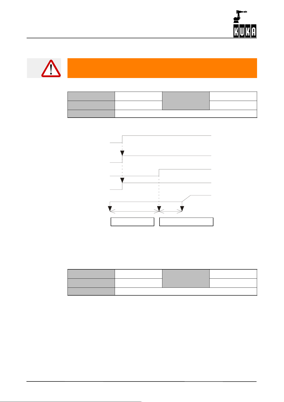
Machine Data
Val
Val
2.1.105 $BRK_OPENTM
This machine datum may only be modified if it is absolutely certain that the
modification will not endanger persons.
Delay of command velocity output
Data type int
min
1
ue
Unit ms
max
-- --
Assignment -- --
Delay of command velocity output after the axis brakes have been opened (prevents motion
“against the brakes”).
Start
Open brakes
“Brake open”
Activate servos
Command value
$BRK_OPENTM Signal processing time
2.1.106 $BRK_DEL_COM
Time after which the axis brakes are closed on completion of positioning in the
command mode
Data type int
Unit ms
Assignment -- --
Fig. 6 Delay
ue
min
max
-- --
-- --
Maschi nendaten 12.0400 en
52 of 91

2 The file $MACHINE.DAT (continued)
Val
Command position
output
Brake signal
1
(Brakes open)
0
(Brakes closed)
Servos activated
1
(on)
0
(off)
Axis in position
t
$BRK_DEL_COM
$BRK_DEL_PRO $SERV_OFF_TM
2.1.107 $BRK_DEL_PRO
Time after which the axis brakes are closed on completion of positioning in program
mode
Data type int
Unit ms
Assignment -- --
See Fig. 7.
Fig. 7 Closing the axis brakes
ue
min
max
-- --
-- --
Maschi nendaten 12.0400 en
53 of 91

Machine Data
Val
Val
2.1.108 $BRK_DEL_EX
Brake delay time for external axes
Data type int
Unit ms
Assignment
“$BRK_DEL_EX” defines the delay time after which the brakes of the external axes close.
This entry is only active if bit 3 is set in “$BRK_MODE” (see Section 2.1.104).
2.1.109 $SERV_OFF_TM
Axis servo and axis brake overlap time
Data type int
Unit ms
Assignment -- --
Time during which axis servo and axis brake overlap in order to locate the axis securely.
See Fig. 7.
ue
[1] axis 1 ... [6] axis 6
[7] external axis 1 ... [12] external axis 6
ue
min
max
min
max
-- --
-- --
-- --
-- --
2.1.110 $MS_DA
Modification of this machine datum constitutes a major danger to persons
and is thus not permitted.
This machine datum is used exclusively for KUKA--internal development purposes.
Maschi nendaten 12.0400 en
54 of 91

2.1.111 $FFC_VEL
Val
Val
Val
Velocity feed forward control switching
2 The file $MACHINE.DAT (continued)
Data type bin
Unit -- --
Assignment -- --
Bit sequence
LSB: Axis 1
MSB: Axis 12
0Off
1On
2.1.112 $FFC_TORQ
Torque pre--control
Data type bool
Unit -- --
Assignment -- --
Torque pre--control On/Off is only used in conjunction with higher motion profile. In the case
of non--KUKA kinematic systems with deactivated acceleration adaptation
($ADAP_ACC=#NONE) and deactivated higher motion profile ($OPT_MOVE=#NONE), it
must be switched off.
ue
ue
min
max
min
max
-- --
-- --
-- --
-- --
Description of the valid values:
TRUE = activated
FALSE = deactivated
2.1.113 $GEARTORQ_MON
Control of gear torque monitoring
Data type bool
Unit -- --
Assignment -- --
Gear torque monitoring On/Off is only used in conjunction with higher motion profile. In the
case of non--KUKA kinematic systems with deactivated acceleration adaptation
($ADAP_ACC=#NONE) and deactivated higher motion profile ($OPT_MOVE=#NONE), it
must be switched off.
TRUE: Activated using the limits (% of the maximum accelerating torques) defined in the data
$DYN_DAT[231]--$DYN_DAT[236] in $robcor.dat.
FALSE: Deactivated
ue
min
max
-- --
-- --
Maschi nendaten 12.0400 en
55 of 91

Machine Data
Val
Val
Val
2.1.114 $SERVOMODE
Controller functions
Data type int
Unit -- --
Assignment -- --
This machine datum is used exclusively for KUKA--internal development purposes.
2.1.115 $ACC_ACT_MA
Limit value of axial command acceleration
Data type int
Unit %
Assignment -- --
a_soll_max=$ACC_ACT_MA/100*“Maximum motor speed”/$raise_time
V_soll_max=$VEL_ACT_MA/100* “Maximum motor speed”*“Reduction factor”/100
“Maximum motor speed”=
G $VEL_AXIS_MA with deactivated energy monitoring ($energy_mon=false) and
non--KUKA kinematic systems.
G With active energy monitoring ($energy_mon=true), a value is calculated from the
dynamic model DYN_DAT[249--254].
ue
ue
min
max
min
max
-- --
-- --
-- --
-- --
2.1.116 $VEL_ACT_MA
Limit value of axial command velocity
Data type real
Unit %
Assignment -- --
V_soll_max=$VEL_ACT_MA/100* “Maximum motor speed”*“Reduction factor”/100
“Maximum motor speed”=
G $VEL_AXIS_MA with deactivated energy monitoring ($energy_mon=false) and
non--KUKA kinematic systems.
G With active energy monitoring ($energy_mon=true), a value is calculated from the
dynamic model DYN_DAT[249--254].
ue
min
max
-- --
-- --
Maschi nendaten 12.0400 en
56 of 91

“Reduction factor”=
Val
Val
G $RED_VEL_AXC in jog mode
G $RED_T1 for PTP/PTP--PTP in T1 mode
G $VEL_CPT1_MA for CP/CP--CP/CP--PTP/PTP--CP in T1 mode
G $RED_VEL_AXC for BCO run with PTP
G $VEL_CPT1_MA for BCO run with CP
In all other cases: 100%.
2.1.117 $IN_POS_CAR
Cartesian positioning window (translation section)
2 The file $MACHINE.DAT (continued)
Data type real
Unit mm
Assignment -- --
2.1.118 $IN_POS_ORI
Cartesian positioning window (orientation section)
Data type real
Unit degrees
Assignment -- --
ue
ue
min
max
min
max
-- --
-- --
-- --
-- --
Maschi nendaten 12.0400 en
57 of 91
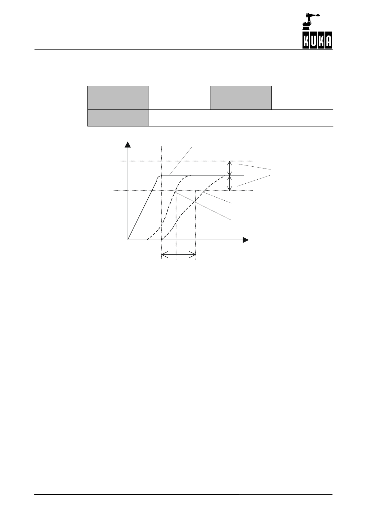
Machine Data
Val
2.1.119 $IN_POS_MA[ ]
Positioning window
Data type real
Unit mm, degrees
Assignment
[1] axis 1 ... [6] axis 6
[7] external axis 1 ... [12] external axis 6
Positioning window in mm (degrees)
$TIME_POS
Command value
min
-- --
ue
max
-- --
$IN_POS_MA
Positioning time exceeded
Axis in position
t
Fig. 8 Positioning window
During positioning, a check is made in the position controller for each axis to see whether
the following error is inside the positioning window for [axis velocity = 0] within the time
specified ($TIME_POS).
If the following error is larger after this time has elapsed, a corresponding error message is
generated.
Default value = 0.1
For linear axes = 1.5 mm
For motor type E = 0.2
Maschi nendaten 12.0400 en
58 of 91
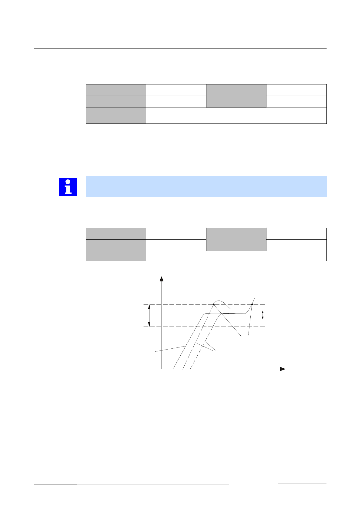
2.1.120 $TIME_POS[ ]
Val
Val
Positioning time
2 The file $MACHINE.DAT (continued)
Data type int
Unit ms
Assignment
During positioning, a check is made in the position controller for each axis to see whether
the following error is inside the positioning window for [axis velocity = 1] within the time
specified ($TIME_POS).
This entry is fixed.
Default value = 512
See Fig. 8
2.1.121 $IN_STILL_MA
Factor for standstill window (see Fig. 9)
Data type int
Unit -- --
Assignment -- --
ue
[1] axis 1 ... [6] axis 6
[7] external axis 1 ... [12] external axis 6
ue
min
max
min
max
512
512
-- --
-- --
The size of the window is defined by $IN_STILL_MA*$IN_POS_MA.
s
Standstill window
Standstill window
Input value
Axes
limit value exceeded
Fig. 9 Standstill window
Positioning window
t
Maschi nendaten 12.0400 en
59 of 91

Machine Data
Val
Val
Val
2.1.122 $FOL_ERR_MA[ ]
Factor for following error monitoring on the DSE
Data type real
Unit []
Assignment
The definition of the monitoring window for following error monitoring refers to $IN_POS_MA
* $FOL_ERR_MA
If the value is exceeded, the error message “Regulator limit exceeded Ax” is generated and
maximum braking is triggered.
This entry is fixed.
Default value = 20.0
2.1.123 $VEL_ENC_CO
Command speed threshold for encoder monitoring
Data type int
Unit -- --
Assignment -- --
This machine datum is used exclusively for KUKA--internal development purposes.
ue
[1] axis 1 ... [6] axis 6
[7] external axis 1 ... [12] external axis 6
ue
min
max
min
max
20.0
20.0
-- --
-- --
2.1.124 $COM_VAL_MI[ ]
Command speed limitation
Data type real
Unit %
Assignment
Limitation of axis command speed.
The command speed value is limited to the value specified in $COM_VAL_MI.
This entry is fixed.
Default value = 150.0
ue
[1] axis 1 ... [6] axis 6
[7] external axis 1 ... [12] external axis 6
min
max
150.0
150.0
Maschi nendaten 12.0400 en
60 of 91

2.1.125 $TL_COM_VAL
Val
Val
Val
Val
Tolerance time after exceeding the command speed limitation
2 The file $MACHINE.DAT (continued)
Data type int
Unit ms
Assignment -- --
If the command speed is still greater than the limit value defined in $COM_VAL_MI after the
time defined in $TL_COM_VAL has elapsed, the error message “Command velocity
exceeded” is generated.
This entry is fixed.
Default values = 50.0 and 50.0
2.1.126 $TOUCH_VEL
Maximum retract velocity for touch sensor
Data type int
Unit %
Assignment -- --
2.1.127 $TOUCH_ACC
Retract acceleration for touch sensor
Data type int
Unit %
Assignment -- --
ue
ue
ue
min
max
min
max
min
max
50
50
-- --
-- --
-- --
-- --
2.1.128 $SOFTN_END[ ]
Software limit switches in the minus direction
Data type real
Unit mm, degrees
Assignment
In the mastered state, the range of motion of the axes can be restricted using software limit
switches.
ue
[1] axis 1 ... [6] axis 6
[7] external axis 1 ... [12] external axis 6
min
max
-- --
-- --
Maschi nendaten 12.0400 en
61 of 91

Machine Data
Val
Val
Val
2.1.129 $SOFTP_END[ ]
Software limit switches in the plus direction
Data type real
Unit mm, degrees
Assignment
In the mastered state, the range of motion of the axes can be restricted using software limit
switches.
Example
$SOFTP_END[7]=180.0
$SOFTP_END[8]=190.0
2.1.130 $AXWORKSPACE
Axis--specific workspaces
Data type real
Unit -- --
Assignment
ue
[1] axis 1 ... [6] axis 6
[7] external axis 1 ... [12] external axis 6
ue
[1] axis 1 ... [6] axis 6
[7] external axis 1 ... [12] external axis 6
min
max
min
max
-- --
-- --
-- --
-- --
“$AXWORKSPACE” is an axis--specific workspace monitoring function similar to the
Cartesian workspace monitoring function.
A maximum of eight workspaces can be defined via KRL system variables.
2.1.131 $BRK_MAX_TM
Maximum braking time for path--maintaining EMERGENCY STOP
Data type int
Unit ms
Assignment -- --
If the time is exceeded, the error message “Max. braking distance exceeded” is generated.
ue
min
max
-- --
-- --
Maschi nendaten 12.0400 en
62 of 91
2.1.132 $EMSTOP_TIME
Val
Val
Val
Val
Time monitoring for path--maintaining EMERGENCY STOP
2 The file $MACHINE.DAT (continued)
Data type int
Unit ms
Assignment -- --
If the robot is not stationary after the time defined in “$EMSTOP_TIME”, the drives
contactor is switched off.
2.1.133 $ACT_VAL_DIF
Max. permissible difference of encoder actual values
Data type int
Unit -- --
Assignment -- --
Maximum permissible difference of the encoder actual values, in increments, before and
after the controller is booted.
2.1.134 $TRAFONAME
Name of coordinate transformation
Data type char
Unit -- --
Assignment -- --
ue
ue
ue
min
max
min
max
min
max
-- --
-- --
-- --
-- --
-- --
-- --
This makes it possible to assign the transformation a symbolic name. It is also compared with
the robot names programmed on the RDC ($ROBTRAFO).
2.1.135 $KINCLASS
Kinematic classes
Data type char
Unit -- --
Assignment -- --
The machine datum defines the “kinematic class”.
Permissible values are:
G #STANDARD
This value activates a transformation that is configured using the following data.
ue
min
max
-- --
-- --
Maschi nendaten 12.0400 en
63 of 91

Machine Data
Val
Val
G #NONE
This value is for kinematic systems for which no transformation exists. These can then
nonetheless be moved in axis--specific mode.
Programs can only be taught in the KRL assistant (axis--specific) or at Expert level
(axis--specific).
The machine datum also has the values #TEST and #SONDER. These are meaningless,
however, and must not be used.
2.1.136 $AX_SIM_ON
This machine datum may only be modified if it is absolutely certain that the
modification will not endanger persons.
Simulation of the closed speed control loop for axis ...
Data type real
Unit -- --
Assignment -- --
Bit array of the simulated axes. This allows the simulation of axes that may not actually be
present. It is thus possible, for example, to implement main axis kinematic systems with
fewer than three degrees of freedom.
The thing to remember here is that the position of the simulated axes when the system is
run up is initialized either to 0 (configured DSE channel present, but no RDC channel) or to
the value of the corresponding axes in $H_POS (no DSE channel available for this axis).
Bit sequence:
G LSB: Axis 1
G MSB: Axis 12
2.1.137 $SIMULATED_AXIS
Simulation of robot axes
Data type bin
Unit -- --
Assignment
ue
ue
[1] axis 1 ... [6] axis 6
[7] external axis 1 ... [12] external axis 6
min
max
min
max
-- --
-- --
-- --
-- --
Axes are included in the planning, but are not moved.
Maschi nendaten 12.0400 en
64 of 91

2.1.138 $TRAFO_AXIS
Val
Val
Number of transformed axes
2 The file $MACHINE.DAT (continued)
Data type int
Unit -- --
Assignment -- --
This machine datum specifies the number of transformed axes.
The value must be between 4 and 6, even if, for example, only three axes are physically
present, and can differ from the value of $NUM_AX.
2.1.139 $MAIN_AXIS
Main axis identification
Data type real
Unit -- --
Assignment -- --
Main axes is the designation given to the first three robot axes. These can be designed as
either rotating or linear joints. Two consecutive main axes are either parallel or perpendicular
to one another.
This means that a maximum of 12 geometrically different arrangements are possible.
Eight of these arrangements can be configured using this machine datum.
Description of the permissible values:
ue
ue
min
max
min
max
-- --
-- --
-- --
-- --
G #SS = Gantry
G #CC = SCARA
Z
iro
Y
iro
X
iro
$LENGTH_A
Fig. 10 #SS configuration
r3
q3
P3
Maschi nendaten 12.0400 en
65 of 91

Machine Data
Z
iro
Y
iro
r3
q3
G #NR = Jointed--arm robot
Z
iro
X
iro
$LENGTH_A $LENGTH_B
Fig. 11 #CC configuration
Y
iro
X
iro
$LENGTH_A $LENGTH_B
Fig. 12 #NR configuration
r3
P3
q3
P3
G #SC = Gantry/SCARA
Z
iro
Y
iro
X
iro
$LENGTH_A
Fig. 13 #SC configuration
r3
q3
P3
66 of 91
Maschi nendaten 12.0400 en

G #RR
2 The file $MACHINE.DAT (continued)
G #CS
Z
iro
Y
iro
X
iro
Z
iro
Y
iro
X
iro
$LENGTH_A
Fig. 14 #RR configuration
Z
iro
Y
iro
X
iro
r3
q3
P3
Maschi nendaten 12.0400 en
$LENGTH_A
Fig. 15 #CS configuration
67 of 91

Machine Data
G #NN
q3
P3
r3
$LENGTH_A
G #RN
$LENGTH_B
Z
iro
Y
iro
X
iro
Fig. 16 #NN configuration
$LENGTH_A $LENGTH_B
Z
iro
Y
iro
r3
q3
68 of 91
X
iro
P3
Fig. 17 #RN configuration
(The other four possible configurations #SN, #CR, #NS and #RC are not implemented.)
Maschi nendaten 12.0400 en

2.1.140 $WRIST_AXIS
Val
Val
Wrist axis identification
2 The file $MACHINE.DAT (continued)
Data type real
min
-- --
ue
Unit -- --
max
-- --
Assignment -- --
This configures the kinematic structure of the wrist.
Description of the permissible values:
G #NOH = no wrist transformation
G #ZEH = in--line wrist; the three wrist axes intersect and are perpendicular to one
another, i.e. the Denavit--Hartenberg parameters are defined and must be
a4=a5=d5=0, a4=±90 degrees, a5=±90 degrees.
G #SRH = oblique wrist; the three wrist axes intersect at a single point, i.e. the
Denavit--Hartenberg parameters a4=a5=d5=0 are defined; any value (greater than 10
degrees) can be selected for a4 and a5.
G #DSH = triple--roll wrist; only the “oblique angle” a can be freely selected and is entered
in $DH_4.ALPHA; the values for a4=a5=d5=0 and a5=--2a are fixed.
G #WIH offset wrist; the three wrist axes are perpendicular to one another, i.e. the
Denavit--Hartenberg parameters a4=±90 degrees, a5=±90 degrees are fixed; a4, d5
and a5 can be freely selected.
G #WSH = oblique offset wrist; this is the “most general” wrist; all DH parameters (with
the exception of d4 which is always 0!) can be freely selected.
2.1.141 $A4_PAR
Axis 4 parallel to the last rotational main axis
Data type int
min
ue
Unit -- --
max
Assignment -- --
This specifies whether axis 4 is parallel to the last rotational main axis:
0 = not parallel; 1 = parallel.
0
1
Maschi nendaten 12.0400 en
69 of 91

Machine Data
Val
Val
2.1.142 $DEF_A4FIX
Fixed positioning of axis 4 and simultaneous control of axis 5 in palletizing mode
Data type bool
Unit -- --
Assignment -- --
This machine datum must be set to TRUE for the 5--axis palletizing robot. In the case of
Cartesian positions, the orientation is modified so that the flange is always parallel to the floor.
The position remains identical.
In the case of axis--specific positions, the angle of axis 5 is adapted in such a way that the
flange is parallel to the floor (this naturally causes the Cartesian position to change).
This setting is only permissible for type #NR and only for floor-- or ceiling--mounting (can be
seen from $ROBROOT and $TIRORO).
The value of $DEF_A4FIX also serves as a default setting for $PAL_MODE.
Description of the permissible values:
G TRUE = Palletizing mode on by default
G FALSE = Palletizing mode off by default
2.1.143 $DEF_A5LINK
4--axis palletizing mode control
Data type bool
Unit -- --
Assignment -- --
ue
ue
min
max
min
max
-- --
-- --
-- --
-- --
This machine datum must be set to TRUE for the 4--axis palletizing robot. $DEF_A4FIX is
then also implicitly set to TRUE. This setting is also only permissible for type #NR and is only
meaningful if the robot is mounted on the floor.
$PAL_MODE must not be set to FALSE in this case!
Description of the permissible values:
G TRUE = 4--axis palletizing mode activated
G FALSE = 4--axis palletizing mode deactivated
If 4--axis palletizing mode is activated, axes 4 and 5 are automatically switched internally
to axis simulation. The assignment of $DEF_A4FIX is ignored.
Maschi nendaten 12.0400 en
70 of 91

2.1.144 $SPINDLE
Val
Val
Spindles
2 The file $MACHINE.DAT (continued)
Data type int
Unit -- --
Assignment -- --
Description of the permissible values:
G 0=No
G 1=Yes
2.1.145 $AXIS_SEQ
Change in sequence from axis ... to axis ...
Data type real
Unit -- --
Assignment [1] axis 1 ... [6] axis 6
Assignment of the axes.
With certain kinematic systems it is possible to interchange the axes without this resulting
in a different kinematic behavior.
With main axes #SS and #CC, for example, the axes can be freely interchanged; with #CS
and #SC it is possible to interchange axes 1 and 2 or 2 and 3. This interchange is carried out
using $AXIS_SEQ[]. $AXIS_SEQ[i]=j thus means that axis j corresponds to the normal
axis i.
ue
ue
min
max
min
max
0
1
-- --
-- --
In the case of a SCARA robot (#CC), for example, axis 1 is usually the linear axis.
$AXIS_SEQ[1]=3 defines axis 3 as the linear axis.
A change to the axis sequence of other kinematic systems is not rejected. It is thus
necessary to use this machine datum with extreme caution!
Maschi nendaten 12.0400 en
71 of 91

Machine Data
Val
Val
2.1.146 $AXIS_DIR[ ]
Direction of rotation of the axes for the transformation
Data type int
min
-- --
ue
Unit -- --
Assignment
[1] axis 1 ... [6] axis 6
[7] external axis 1 ... [12] external axis 6
max
-- --
It is only the direction of rotation for the transformation that is defined by the machine datum.
The rotational axis and thus direction of rotation (for the transformation) of the main axes is
defined by the definition of the coordinate systems I RO and X3. This machine datum is thus
required for the free selection of any direction of rotation.
The actual direction of rotation of an axis is not affected by $AXIS_DIR. This can only be
modified by means of the sign preceding the value for the gear ratio ($RAT_MOT_AX).
Mathematically positive = 1
Mathematically negative = --1
Definition of the direction of rotation is only meaningful once the external axes have been
calibrated.
Example
In the example, the sign of the angle of axis 2 is inverted in the transformation. If the axis
is at --10 degrees, for example, the transformation works on the basis of +10 degrees.
2.1.147 $INC_AXIS
Incremental dimension, axis--specific
Data type real
Unit degrees, mm
Assignment [1] axis 1 ... [6] axis 6
$AXIS_DIR[2]=-1
ue
min
max
-- --
-- --
Maschi nendaten 12.0400 en
72 of 91

2.1.148 $INC_EXTAX[ ]
Val
Val
Val
Axis--specific increment of external axes
2 The file $MACHINE.DAT (continued)
Data type real
Unit increments
Assignment [1] axis 1 ... [6] axis 6
The increment for an axis is the distance moved by the robot each time a jog key is pressed.
Example
2.1.149 $INC_CAR[ ]
Increment, Cartesian, relative to the tool
Data type real
Unit degrees, mm
Assignment [1]... [6]
2.1.150 $POS_SWB[ ]
$INC_EXTAX[1]=10.0
$INC_EXTAX[2]=10.0
ue
ue
min
max
min
max
-- --
-- --
-- --
-- --
Modification of Status for singularities
Data type int
min
-- --
ue
Unit -- --
max
-- --
Assignment -- --
For each of the max. three singularities, it is possible to specify here whether or not
modification of the solution branch, i.e. the status, is permissible during a CP motion.
Modification can, however, lead to velocity--dependent axis positions and does not solve the
underlying problem of the singularities. We therefore recommend leaving this value always
set to 0.
Description of the permissible values:
0=NO
1 = YES
Example
Singularity 1 – modification of Status is not to be possible:
$POS_SWB[1]=0
Maschi nendaten 12.0400 en
73 of 91

Machine Data
Val
Val
Val
2.1.151 $SINGUL_POS
Treatment of an undefined joint positions
Data type int
Unit -- --
Assignment [1] [2] [3]
Configuration of the treatment of undefined joint positions on specification of a singular PTP
end point.
Description of the permissible values:
The value 0 means that the corresponding axis is moved to 0 degrees, while the value 1
means that the axis value of the start point is used.
0 Use theta=0 degrees
1 Use old value of theta
Example
If the end point of a PTP motion results in the wrist singularity (Alpha 5), the angles of
axes 4 and 6 cannot be determined unambiguously.
If $SINGUL_POS[3] is equal to 0, the angle of axis 4 will in any case be moved to
0 degrees, while the value 1 means that the value of the start point is retained for
axis 4. The angle of axis 6 is then adapted accordingly.
2.1.152 $DIS_WRP1
Average distance of wrist point from singularity 1 (Alpha1 singularity)
ue
min
max
0
1
Data type real
Unit -- --
Assignment -- --
2.1.153 $DIS_WRP2
Average distance of wrist point from singularity 2 (Alpha5 singularity)
Data type real
Unit -- --
Assignment -- --
ue
ue
min
max
min
max
-- --
-- --
-- --
-- --
Maschi nendaten 12.0400 en
74 of 91

2.1.154 $ORI_CHECK
Val
Val
Orientation check at CP end points (only with five--axis robots)
2 The file $MACHINE.DAT (continued)
2.1.155 $TIRORO
Data type int
min
-- --
ue
Unit -- --
max
-- --
Assignment -- --
In the case of 5--axis robots, one degree of freedom is missing. This means that it is not
possible to set a default value for the orientation angle C.
There are two possibilities, however, for addressing a Cartesian position. The only difference
here is a difference of 180 degrees for angle C.
If $ORI_CHECK is set to 1, a check is carried out to see whether or not the 5--axis robot
reached the taught end point.
Offset between internal and current robot coordinate system
Data type real
min
-- --
ue
Unit -- --
max
-- --
Assignment FRAME {X, Y, Z, A, B, C}
$TIRORO
A3
Z
3
Y
3
R=90 degrees
X
3
A5
A4 A6
Z
IRO
Y
IRO
A2
X
IRO
a b $TX3P3 $TFLWP
A1
Z
RO
Y
RO
WP
X
WP
Y
WP
Z
WP
FL
Y
FL
Z
FL
X
FL
Maschi nendaten 12.0400 en
X
RO
Fig. 18 TIRORO
This frame represents the position of the internal robot coordinate system (IRO) in the
externally visible robot base system (RO).
75 of 91

Machine Data
Val
Val
Val
Val
2.1.156 $TFLWP
Offset between flange point and wrist point coordinate system
Data type real
Unit -- --
Assignment FRAME {X, Y, Z, A, B, C}
(See Fig. 18.) Link frame between the last wrist coordinate system (WP) and t he externally
visible flange system (FL) (representation of FL system in the WP system).
2.1.157 $TX3P3
Offset of robot wrist, based on axis 3
Data type real
Unit -- --
Assignment FRAME {X, Y, Z, A, B, C}
Link frame between the last main axis system (P3) and the first wrist coordinate system (X3)
(representation of the X3 system in the P3 system).
Bear in mind that coordinate system P3 does not correspond to the DH convention as robot
axis 3 in the standard robot (#NR), for example, rotates about the Y3 axis of the P3 system.
The Z axis of the first wrist axis system X3 must be parallel (or antiparallel) to rotational
axis 4, as the wrist is described using DH parameters.
2.1.158 $LENGTH_A
ue
ue
min
max
min
max
-- --
-- --
-- --
-- --
Main axis length A, eccentricity of axis 2 relative to axis 1
Data type real
Unit -- --
Assignment -- --
This is a geometrical length that depends on the specific main axis kinematic system that
has been set.
2.1.159 $LENGTH_B
Main axis length B, link arm length
Data type real
Unit -- --
Assignment -- --
This is a geometrical length that depends on the specific main axis kinematic system that
has been set.
ue
ue
min
max
min
max
-- --
-- --
-- --
-- --
Maschi nendaten 12.0400 en
76 of 91

2.1.160 $DH_4
Val
Val
2 The file $MACHINE.DAT (continued)
Denavit--Hartenberg parameters
2.1.161 $DH_5
Data type real
min
-- --
ue
Unit -- --
max
-- --
Assignment -- --
Length A DHART_A
Length D DHAR T_D
Angle a DHART_ALPHA
Denavit--Hartenberg parameters a, d and a for frame between axis 4 and 5, or 5 and 6.
$DH_4.D is always 0 and two consecutive wrist axes must not be “quasi--parallel”, i.e. |a|
must not be less than 10 degrees.
Caution: The initial system X3 in axis 4 is defined by $TX3P3. Only the Z axis is defined by
X3. The position of the X axis can be “freely” selected, thus giving rise to a number of
configuration options, each with a different zero position of the wrist axes.
Denavit--Hartenberg parameters
Data type -- --
min
-- --
ue
Unit -- --
max
-- --
Assignment -- --
Length A DHART_A
Length D DHART_D
Angle a DHART_ALPHA
Denavit--Hartenberg parameters a, d and a for frame between axis 4 and 5, or 5 and 6.
$DH_4.D is always 0 and two consecutive wrist axes must not be “quasi--parallel”, i.e. |a|
must not be less than 10 degrees.
Caution: The initial system X3 in axis 4 is defined by $TX3P3. Only the Z axis is defined by
X3. The position of the X axis can be “freely” selected, thus giving rise to a number of
configuration options, each with a different zero position of the wrist axes.
Maschi nendaten 12.0400 en
77 of 91
Machine Data
Val
Val
Val
Val
2.1.162 $SPIN_A
2.1.163 $SPIN_B
2.1.164 $SPIN_C
Data type -- --
min
-- --
ue
Unit -- --
max
-- --
Assignment -- --
This machine datum is used exclusively for KUKA--internal development purposes.
Data type -- --
min
-- --
ue
Unit -- --
max
-- --
Assignment -- --
This machine datum is used exclusively for KUKA--internal development purposes.
Data type -- --
min
-- --
ue
Unit -- --
max
-- --
Assignment -- --
2.1.165 $TRP_A
This machine datum is used exclusively for KUKA--internal development purposes.
Axis driven by trapezoid
Data type -- --
min
-- --
ue
Unit -- --
max
-- --
Assignment -- --
This machine datum is used exclusively for KUKA--internal development purposes.
Maschi nendaten 12.0400 en
78 of 91

2.1.166 $SPC_KIN
Val
Val
Val
Data for special kinematics
2 The file $MACHINE.DAT (continued)
Data type real
Unit -- --
Assignment [1] ... [30]
This machine datum is used exclusively for KUKA--internal development purposes.
2.1.167 $ASR_ERROR
Permissible speed deviation (external position encoder/motor encoder)
Data type real
Unit -- --
Assignment [1] ... [30]
If an external position encoder is used, “$ASR_ERROR” specifies the permissible deviation
of the speed measured by the motor encoder from that measured by the external encoder.
2.1.168 $RAT_EXT_ENC
Axis--specific encoder ratio of the external encoder
Data type real
Unit -- --
Assignment [1] ... [30]
ue
ue
ue
min
max
min
max
min
max
-- --
-- --
-- --
-- --
-- --
-- --
Example
$RAT_EXT_ENC[1]={N 1,D 4}
If the slave also has an external sensor, the encoder ratio of the slave must be the same
as that of the master.
Maschi nendaten 12.0400 en
79 of 91

Machine Data
Val
2.1.169 $AX_ENERGY_MAX[ ]
Maximum energy of the axis
Data type real
Unit -- --
Assignment
The value must be calculated on a case--by--case basis.
The maximum energy E
energy E
E
max
2.1.169.1Kinetic energy
The kinetic energy E
= E
E
kin
E
trans
E
=
rot
ω = n ⋅
E: Energy [J]
m: Mass [kg]
min
-- --
ue
max
-- --
[1] axis 1 ... [6] axis 6
[7] external axis 1 ... [12] external axis 6
of the axis consists of the potential energy E
max
. It is the energy which must be taken up by the brake in the worst--case situation.
kin
= E
=
J
trans
m
2
motor
2
pot
+ E
⋅ v
⋅ ω
+ E
2
max
kin
rot
2
motor
is the sum of translational E
kin
+
J
gear
⋅ ω
2
2
gear
+
J
structure
2
⋅ ω
2
structure
and rotational energy E
trans
and the kinetic
pot
π
30
:
rot
v: Velocity [m/s]
2
J: Mass moment of inertia [kg m
]
ω: Angular velocity [1/s]
n: Speed [rpm]
In the case of a cylindrical turntable of mass m and radius r, the following applies:
m
J
structure
=
2
⋅ r
2
Maschi nendaten 12.0400 en
80 of 91

2.1.169.2Potential energy
Val
Val
2 The file $MACHINE.DAT (continued)
The formula for the potential energy E
E
= m ⋅ g ⋅ ∆h
pot
m: Mass [kg]
g: Gravitational acceleration 9.81 [m/s
∆h: Height difference [m]
2.1.169.3Maximum energy of the linear unit
For a linear unit in the plane, ∆h = 0:
m
E
=
max
2
⋅ v
max
2
2.1.169.4Maximum energy of a turntable
For a turntable:
J
=
motor
2
⋅ ω
E
max
2
motor
+
J
gear
2
2.1.170 $BRK_ENERGY_MAX[ ]
Maximum permissible braking energy
Data type real
Unit J
Assignment
[1] axis 1 ... [6] axis 6
[7] external axis 1 ... [12] external axis 6
⋅ ω
2
gear
+
m
:
pot
2
]
turntable
4
⋅ r
2
turntable
⋅ ω
2
turntable
ue
min
max
-- --
-- --
The values here can be read from a table and are dependent on the motor.
2.1.171 $BRK_COOL_OFF_COEFF[ ]
Brake cooling factor
Data type real
Unit J/s
Assignment
The brake cools down again when the system is at standstill. The energy dissipated depends
on the cooling factor of the brake.
Example
The first external axis is driven by a motor of type D:
$BRK_COOL_OFF_COEFF[7]=33
ue
[1] axis 1 ... [6] axis 6
[7] external axis 1 ... [12] external axis 6
min
max
-- --
-- --
Maschi nendaten 12.0400 en
81 of 91

Machine Data
Val
2.1.172 $BRK_TORQUE[ ]
Dynamic braking torque
Data type real
min
-- --
ue
Unit Nm
Assignment
[1] axis 1 ... [6] axis 6
[7] external axis 1 ... [12] external axis 6
max
-- --
The energy taken up by the brake depends on the dynamic braking torque.
Example
The first external axis is driven by a motor of type D:
$BRK_TORQUE[7]=5
Maschi nendaten 12.0400 en
82 of 91

2.2 Machine data for external axes
Val
Val
The last machine data in $Machine.dat are for the configuration of external axes.
The following sections contain descriptions of all the machine data for external axes.
More detailed information on external axes can be found in the documentation
“Configuration (Machine Data)” / “External Axes”.
2.2.1 $EX_AX_NUM
Number of external axes
2 The file $MACHINE.DAT (continued)
Data type int
Unit -- --
Assignment
“$EX_AX_NUM” defines the number of external axes that are connected to the robot system.
Example
Three external axes are present:
2.2.2 $EX_AX_ASYNC
Switching external axes to asynchronous motion
Data type int
Unit -- --
Assignment
[1] axis 1 ... [6] axis 6
[7] external axis 1 ... [12] external axis 6
$EX_AX_NUM=3
[1] axis 1 ... [6] axis 6
[7] external axis 1 ... [12] external axis 6
ue
ue
min
max
min
max
-- --
-- --
-- --
-- --
Maschi nendaten 12.0400 en
This option makes it possible to move the external axes independently of the robot axes.
Synchronous external axes: The robot axes and external axes start to move
simultaneously and stop simultaneously.
83 of 91

Machine Data
Val
Asynchronous external axes: Motion of the external axes starts and stops independently
of the robot axes.
Bit no. 1 0
Meaning E2 E1
G Bit = 1 ----> corresponding axis is switched to asynchronous mode
G Bit = 0 ----> corresponding axis is switched to synchronous mode
Example
All external axes are switched to synchronous mode:
2.2.3 $ASYNC_T1_FAST
Velocity reduction factor in T1 mode
$EX_AX_ASYNC=’B0000’
Data type int
min
-- --
ue
Unit -- --
Assignment
[1] axis 1 ... [6] axis 6
[7] external axis 1 ... [12] external axis 6
max
-- --
Deactivation of the T1 velocity reduction factor of asynchronous external axes.
Syntax:
$ASYNC_T1_FAST = V alue
Argument Type Explanation
This bit--coded value specifies which external axis may be
moved in the case of coordinated asynchronous motions
without velocity reduction in T1 mode:
-- The bits correspond to the external axes in ascending order:
Value INT
Bit 0 = external axis 1, Bit 1 = external axis 2, etc.
-- If the bit is set, the external axis may be moved, in the case
of coordinated asynchronous motions in T1 mode, at
maximum velocity.
Maschi nendaten 12.0400 en
84 of 91

2 The file $MACHINE.DAT (continued)
Description:
In the machine data, $ASYNC_T1_FAST specifies the external axes for which the velocity
reduction in controller mode T1 can be canceled for ASYPTP motions.
Whether or not an ASYPTP motion is executed in T1 mode without velocity reduction, i.e.
at program velocity, depends on the axes involved in the motion. An axis is involved in the
motion if it is actually moved, i.e. it is part of the motion instruction and the start value and
end value are not identical.
This means:
G If the corresponding bit is set in $ASYNC_T1_FAST for all the axes involved in the
ASYPTP motion, the motion is executed in T1 mode at program velocity.
G If, for at least one of the axes involved in the ASYPTP motion, the corresponding bit
is not set in $ASYNC_T1_FAST, the motion is executed in T1 mode at reduced velocity.
Remarks:
G Deactivation of the T1 velocity reduction may only be used for external axes of special
applications which are not safety--sensitive (e.g. electric motor--driven spot welding
gun).
G The value can only be altered in the machine data; other assignments are not possible.
G Bits may only be set for external axes that are actually present (configured via
$EX_AX_NUM in the machine data). If, however, no external axes are present
($EX_AX_NUM = 0), the value is not checked.
Example
Velocity reduction activated for all external axes:
INT $ASYNC_T1_FAST=’B0000’
Velocity reduction deactivated for E1:
INT $ASYNC_T1_FAST=’B0001’
Maschi nendaten 12.0400 en
85 of 91

Machine Data
Val
2.2.4 $ASYNC_EX_AX_DECOUPLE
Decoupled external axes
Data type int
min
-- --
ue
Unit -- --
Assignment
[1] axis 1 ... [6] axis 6
[7] external axis 1 ... [12] external axis 6
max
-- --
Decoupling of external axes with the position and DSE data saved for subsequent
recoupling.
Decoupling an axis means that this axis is considered by the controller to be no longer
present; in particular, the axis cannot be moved and all monitoring functions are deactivated.
In the case of coordinated synchronous motions (PTP , LIN, CIRC ...), a decoupled axis is
not taken into consideration. This is because the axis is automatically switched to
asynchronous mode.
In the case of coordinated asynchronous motions (ASYPTP), a decoupled axis is not taken
into consideration.
Synchronous and asynchronous manual motions (MOVE, AJOG) of a decoupled external
axis are rejected and an error message is generated.
A decoupled axis cannot be mastered using the normal mastering procedure in which the
axis must be moved. An attempt to master such an axis in this way will be rejected and an
error message will be generated.
The characteristics described above mean that this “functional” decoupling of an external
axis in KRL makes it possible to change this axis electrically (and mechanically) while the
robot system is in operation.
Decoupled external axes are automatically switched to asynchronous mode in
$ASYNC_AXIS.
The flag $ASYNC_OPT for enabling the asynchronous functionality must be set to TRUE.
When $ASYNC_EX_AX_DECOUPLE is defined, an advance run stop is triggered if the
value changes. Before a new value is saved, the system will wait until all synchronous
motions (through advance run stop) and all asynchronous motions have been completed,
and all axes are in position.
The axes to be decoupled may not be coupled mechanically or mathematically with other
axes; most importantly, the axis may not be part of an external kinematic system.
Maschi nendaten 12.0400 en
86 of 91

$ASYNC_EX_AX_DECOUPLE can only be set in the brake control mode “Individual
external axis brake control” (bit 3 of $BRK_MODE is set).
Invalid assignments will be rejected and a corresponding error message will be generated.
Bit no. 1 0
Meaning E2 E1
1= axis decoupled
0= axis coupled
Example
All external axes are coupled:
ASYNC_EX_AX_DECOUPLE=’B0000’
2.2.4.1 Interaction with system variables
$ASYNC_EX_AX_DECOUPLE changes or influences other KRL system variables:
$ASYNC_AXIS:
2 The file $MACHINE.DAT (continued)
If a bit is set in $ASYNC_EX_AX_DECOUPLE, the corresponding bit is also set in
$ASYNC_AXIS, i.e. the axis is switched to asynchronous mode. The status message for the
asynchronous axis is not displayed.
If a bit is deleted in $ASYNC_EX_AX_DECOUPLE, $ASYNC_AXIS remains unchanged, i.e.
the axis remains asynchronous. The status message for the asynchronous axis is displayed.
An attempt to switch a decoupled axis to synchronous mode by means of a direct value
assignment to $ASYNC_AXIS will be rejected with an error message.
$AXIS_ACT:
In the case of a decoupled axis, it is possible to assign a value to the corresponding entry
in the variable $AXIS_ACT which is otherwise write--protected. This allows the axis to be
mastered in the KRL program.
$AXIS_JUS:
If a bit is set in $ASYNC_EX_AX_DECOUPLE, the mastering of the corresponding axis is
deleted and the corresponding entry in $AXIS_JUS is set to FALSE.
Maschi nendaten 12.0400 en
87 of 91

Machine Data
Val
Val
2.2.5 $EX_KIN
External kinematic systems
2.2.6 $ET1_AX
Data type real
min
-- --
ue
Unit -- --
Assignment
[1] axis 1 ... [6] axis 6
[7] external axis 1 ... [12] external axis 6
max
-- --
“$EX_KIN” establishes the link between the external transformation in $MACHINE.DAT and
the external kinematic system in $CONFIG.DAT.
#EASYS to #EFSYS = identifier for external base kinematic systems
#ERSYS = identifier for external ROBROOT kinematic system
Example
External transformations 1 and 2 are both base kinematic systems:
DECL EX_KIN $EX_KIN={ET1 #EASYS,ET2 #EBSYS,ET3 #NONE,ET4
#NONE,ET5 #NONE,ET6 #NONE}
External axes
Data type real
min
-- --
ue
Unit -- --
Assignment
[1] axis 1 ... [6] axis 6
[7] external axis 1 ... [12] external axis 6
max
-- --
“$ET1_AX” designates the aggregate containing a list of the external axes which are used
in the 1st external transformation.
Example
The first transformed axis in the kinematic chain, TR_A1, is to be assigned the second
external axis #E2:
DECL ET_AX $ET1_AX={TR_A1 #E2,TR_A2 #NONE,TR_A3 #NONE}
The aggregate must not contain any gaps; the assignments are made from left to right.
Maschi nendaten 12.0400 en
88 of 91

2.2.7 $ET1_NAME[ ]
Val
Val
Val
Name of the transformation
2 The file $MACHINE.DAT (continued)
Data type char
Unit -- --
Assignment
“$ET1_NAME[ ]” contains the name of the transformation.
Example
2.2.8 $ET1_TA1KR
Frame linkage between the root point and A1
Data type real
Unit mm, degrees
Assignment
[1] axis 1 ... [6] axis 6
[7] external axis 1 ... [12] external axis 6
$ET1_NAME[]=“REINHARD_1”
[1] axis 1 ... [6] axis 6
[7] external axis 1 ... [12] external axis 6
ue
ue
min
max
min
max
-- --
-- --
-- --
-- --
“$ET1_TA1KR” defines the transformation between the kinematic root (root point of the
external axis) and the pivot point of axis 1 (the first external axis used in this external
transformation, ET1).
Example
2.2.9 $ET1_TA2A1
Frame linkage between A1 and A2
Data type real
Unit []
Assignment
FRAME $ET1_TA1KR={X 0.0,Y 0.0,Z 427.0,A 0.0,B 0.0,C 90.0}
min
-- --
ue
max
-- --
[1] axis 1 ... [6] axis 6
[7] external axis 1 ... [12] external axis 6
Maschi nendaten 12.0400 en
89 of 91

Machine Data
Val
Val
“$ET1_TA2A1” defines the offset between transformation axis 1 (first external axis used) and
the pivot point of axis 2 (second external axis used in this external transformation, ET1).
Example
2.2.10 $ET1_TA3A2
Frame linkage between A2 and A3
FRAME $ET1_TA2A1={X 0.0,Y 0.0,Z 0.0,A 0.0,B 0.0,C 0.0}
Data type real
Unit mm, degrees
Assignment
“$ET1_TA3A2” defines the offset between transformation axis 2 (second external axis used)
and the pivot point of axis 3 (third external axis used in this external transformation, ET1).
Example
2.2.11 $ET1_TFLA3
Frame linkage between A3 and the flange
Data type real
Unit mm, degrees
Assignment
min
-- --
ue
max
-- --
[1] axis 1 ... [6] axis 6
[7] external axis 1 ... [12] external axis 6
FRAME $ET1_TA3A2={X 0.0,Y 0.0,Z 0.0,A 0.0,B 0.0,C 0.0}
min
-- --
ue
max
-- --
[1] axis 1 ... [6] axis 6
[7] external axis 1 ... [12] external axis 6
“$ET1_TFLA3” defines the offset between transformation axis 3 (third external axis used)
and the flange coordinate system.
Example
FRAME $ET1_TFLA3={X 0.0,Y 0.0,Z 0.0,A 0.0,B 0.0,C 0.0}
Maschi nendaten 12.0400 en
90 of 91

2.2.12 $ET1_TPINFL
Val
Frame linkage between the flange and the measuring point
2 The file $MACHINE.DAT (continued)
Data type real
min
-- --
ue
Unit mm, degrees
Assignment
[1] axis 1 ... [6] axis 6
[7] external axis 1 ... [12] external axis 6
max
-- --
“$ET1_TPINFL” defines the offset between the origin of the kinematic coordinate system and
the reference mark.
Example
FRAME $ET1_TPINFL={X 0.0,Y 0.0,Z 0.0,A 0.0,B 0.0,C 0.0}
1
Maschi nendaten 12.0400 en
91 of 91

Index
A
$A4_PAR, 69
$ACC_ACT_MA, 56
$ACC_CAR_ACT, 37
$ACC_CAR_LIMIT, 37
$ACC_CAR_STOP, 37
$ACC_CAR_TOOL, 36
$ACC_MA, 47
$ACC_OV, 48
Acceleration, 35
Acceleration for override, 36
Acceleration monitoring, 36, 37
$ACT_VAL_DIF, 63
Actual speed monitoring, 33
$ANA_DEL_FLT, 49
Analog output, 49
$APO_DIS_PTP[ ], 46
$ASR_ERROR, 79
$ASYNC_AXIS, 87
$ASYNC_EX_AX_DECOUPLE, 86
$ASYNC_T1_FAST, 84
$AX_ENERGY_MAX[ ], 80
$AX_SIM_ON, 64
Axial acceleration, 34
Axial command acceleration, 56
Axial command velocity, 56
Axial velocity, 34
Axis acceleration time, 31
Axis assignment, 16
Axis sequence change, 71
Axis type, 10
Axis--specific workspaces, 62
$AXIS_ACT, 87
$AXIS_DIR[ ], 72
$AXIS_JUS, 87
$AXIS_RESO[ ], 33
$AXIS_SEQ, 71
$AXIS_TYPE[ ], 10
$AXWORKSPACE, 62
B
$BOUNCE_TIME, 41
Brake control mode, 50
Brake cooling factor, 81
Brake delay time, 54
Braking ramp, 43
Braking time, 62
Braking torque, 82
$BRK_COOL_OFF_COEFF[ ], 81
$BRK_DEL_COM, 52
$BRK_DEL_EX, 54
$BRK_DEL_PRO, 53
$BRK_ENERGY_MAX[ ], 81
$BRK_MAX_TM, 62
$BRK_MODE, 50
$BRK_OPENTM, 52
$BRK_TORQUE[ ], 82
C
Cannon position, 12
Cartesian positioning window, 57
Channel number, 24
$COM_VAL_MI[ ], 60
Command speed, 60
Command speed limitation, 60, 61
Command speed threshold, 60
Command torque to slave/master, 23
Command velocity output, 52
Constant travel phase, 46
Control loop number, 17
Control loop type, 21
Controller functions, 56
Cool--down time, 39
$COOLDOWN_TIME, 39
Coordinate transformation, 63
$COUP_COMP[ ], 11
Coupling, 11
CP velocity, 35
CP end point, 75
CP motion, 43, 44, 48
CP motions, 33, 45
$CURR_CAL[ ], 28
$CURR_COM_EX[ ], 30
$CURR_LIM[ ], 29
$CURR_MAX[ ], 28
$CURR_MON[ ], 29
Current controller, 44
Current limit, 30
Current setpoint limit, 29
Index -- i

Index
D
$DECEL_MB[ ], 43
Decoupled external axes, 86
$DEF_A4FIX, 70
$DEF_A5LINK, 70
$DEF_FLT_CP, 48
$DEF_FLT_PTP, 48
$DEF_OV_JOG, 49
Denavit--Hartenberg parameters, 77
Detection time, 40
$DH_4, 77
$DH_5, 77
Difference of encoder actual values, 63
$DIR_CAL, 49
Direction of rotation of the axes, 72
Direction specification for slave axes, 20
$DIS_WRP1, 74
$DIS_WRP2, 74
DSE channel, 17
DSE channels, 16
DSE control loop, 24, 25
DSE loop, 24, 25
$DSECHANNEL[ ], 16
Dynamic braking, 43
Dynamic braking torque, 82
E
Eccentricity, 76
$EMSTOP_TIME, 63
EMT mastering, 41
EMT mastering travel, 42
EMT signals, 41
Encoder ratio, 79
Energy of the axis, 80
$ERSYSROOT, 14
$ET1_AX, 88
$ET1_NAME[ ], 89
$ET1_TA1KR, 89
$ET1_TA2A1, 89
$ET1_TA3A2, 90
$ET1_TFLA3, 90
$ET1_TPINFL, 91
$EX_AX_NUM, 83
$EX_KIN, 88
$EXCOUP_COM[ ], 11
Extended position, 12
External axes, 83, 88
External kinematic systems, 88
External position encoder/motor encoder, 79
F
$FFC_TORQ, 55
$FFC_VEL, 55
Filtering of the analog output, 49
Finitely rotating, 10
Fixed positioning of axis 4, 70
Flange velocity, 35
$FOL_ERR_MA[ ], 60
Following error monitoring, 60
Force/torque input, 26
Frame chain, 13
Frame linkage, 89, 90, 91
Function generators, 9
G
$G_COE_CUR, 44
$G_VEL_CAL, 42
$G_VEL_CP[ ], 44
$G_VEL_PTP[ ], 44
Gear ratio, 15, 26
Gear torque monitoring, 55
$GEARTORQ_MON, 55
I
I factor, 45
$I_VEL_CP[ ], 45
$I_VEL_PTP[ ], 45
$IN_POS_CAR, 57
$IN_POS_MA[ ], 58
$IN_POS_ORI, 57
$IN_STILL_MA, 59
$INC_AXIS, 72
$INC_EXTAX, 73
$INC_EXTAX[ ], 73
Increment, 72, 73
Infinitely rotating, 10
J
Joint positions, 74
Index -- ii

Index
K
$KINCLASS, 63
Kinematic classes, 63
Kinetic energy, 80
KPS, 18
KPS module, 21
$KPS_CURR_MAX, 30
$KPS_CURR_RA TED, 30
KSD current, 28
KSD output, 28
KT factor, 31
$KT_MOT[ ], 31
KT0 factor, 31
L
$L_EMT_MAX[ ], 42
$LENGTH_A, 76
$LENGTH_B, 76
$LG_CP[ ], 43
$LG_PTP[ ], 42
LINEAR, 10
Linear traversing unit, 14
Link arm length, 76
Loop gain, 42, 43
$LOOP_DIRECTION[ ], 20
$LOOP_G_VEL_PTP[ ], 19
$LOOP_I_VEL_PTP[ ], 20
$LOOP_LG_PTP[ ], 19
$LOOP_RAT_EXTPOS_AX[ ], 26
$LOOP_RAT_MOT_AX[ ], 26
$LOOP_TYPE[Ln], 21
$LOOP_TYPE_ATTRIBUTE[ ], 22
M
Main axis identification, 65
Main axis length, 76
$MAIN_AXIS, 65
$MAMES[ ], 12
$MASTER_LOOP[Ln], 22
Mastering direction, 49
Mastering sequence, 49
Mastering velocity, 50
Maximum energy of a turntable, 81
Maximum energy of the linear unit, 81
Maximum rated current, 30
Measuring system, 33
Motor acceleration time, 32
Motor characteristic, 31
Motor current, 39
Motor/KSD combination, 27
$MOTOR_POLE_NUMBER[ ], 27
$MS_DA, 54
N
$NINPUT_SENSORCHANNEL[Ln], 24
$NINPUT_SENSORTYPE[Ln], 23
$NINPUT_SUBCHANNEL[Ln], 24
$NUM_AX[ ], 10
Number of axes, 10
Number of external axes, 83
O
Offset, 13, 14, 75, 76
$ORI_CHECK, 75
Orientation, 13, 14
Orientation acceleration, 35
Orientation check, 75
Orientation velocity, 35
Override, 39
Override in manual mode, 49
P
Palletizing mode, 70
Path acceleration, 35, 47
Path--maintaining Emergency Stop ramp, 38
$PMCHANNEL[ ], 18
Pole pairs, 27
$POS_SWB, 73
$POSINPUT_SENSORCHANNEL[Ln], 25
$POSINPUT_SENSORTYPE[Ln], 25
$POSINPUT_SUBCHANNEL[Ln], 25
Position controller, 19
Position input, 25
Positioning time, 59
Positioning window, 57, 58
Potential energy, 81
Proportional gain, 44
PTP, 42
PTP motion, 44, 48
PTP motions, 45, 46
Index -- iii

Index
R
$RAISE_T_MOT[ ], 32
$RAISE_TIME[ ], 31
$RAT_EXT_ENC, 79
$RAT_MOT_AX[ ], 15
$RAT_MOT_ENC[ ], 16
Rated motor speed, 32
RDC inputs, 17
$RED_ACC_AXC[ ], 34
$RED_ACC_CPC, 35
$RED_ACC_DYN, 35
$RED_ACC_EMX[ ], 38
$RED_ACC_OV[ ], 36
$RED_CAL_SD, 50
$RED_CAL_SF, 50
$RED_JUS_UEB, 36
$RED_T1, 48
$RED_VEL_AXC[ ], 34
$RED_VEL_CPC, 35
Reduced velocity, 84
Reduction factor for Test 1 mode, 48
Retract acceleration, 61
Retract velocity, 61
$ROBROOT, 13
ROTATIONAL, 10
$SLAVE_TORQUE_RA TIO[ ], 23
$SOFTN_END[ ], 61
$SOFTP_END[ ], 62
Software limit switches, 61, 62
$SPC_KIN, 79
Speed channel, 24
Speed controller, 19, 20, 44, 45
Speed controller gain, 42
Speed deviation, 79
Speed input, 23
$SPIN_A, 78
$SPIN_B, 78
$SPIN_C, 78
$SPINDLE, 71
SPINDLE, 10
Spindles, 71
$ST_TOL_TIME, 40
$ST_TOL_VEL[ ], 40
Standstill current, 29
Standstill detection, 40
Standstill window, 59
$STRP_A, 78
Switching to asynchronous motion, 83
Symmetry of the axes, 43
System requirements, 8
System variables, 87
S
$SEN_DEL[ ], 41
Sensor gear, 26
Sensor location run, 36
Sensor type for the speed input, 23
$SEQ_CAL, 49
$SERV_OFF_TM, 54
Servo file, 27
$SERVOFILE_CONFIG[ ], 27
$SERVOFILEKPS1[ ], 27
$SERVOMODE, 56
Shut--off threshold, 20
$SIMULATED_AXIS, 64
Simulation of robot axes, 64
$SINGUL_POS, 74
Singularities, 73
Slave control loop, 26
$SLAVE_LOOP_FOL_ALARM[ ], 21
$SLAVE_LOOP_FOL_CRITICAL[ ], 20
$SLAVE_LOOP_PMCHANNEL[Ln], 21
$SLAVE_LOOP_SPEED_ALARM[ ], 21
T
Tacho filter $VEL_FILT[ ], 46
$TC_SYM, 43
TCP, 47
$TECH_MAX, 9
Technology packages, 9
$TFLWP, 76
Time monitoring for path--maintaining
EMERGENCY STOP, 63
$TIME_POS[ ], 59
$TIRORO, 75
$TL_COM_VAL, 61
$TM_CON_VEL, 46
$TORQINPUT_SENSORTYPE[Ln], 26
Torque pre--control, 55
Touch sensor, 61
$TOUCH_ACC, 61
$TOUCH_VEL, 61
$TRAFO_AXIS, 65
$TRAFONAME, 63
Transformation, 89
Index -- iv

Transformed axes, 65
Transmission ratio, 16
Turntable, 81
$TX3P3, 76
V
$V_R1MADA[ ], 9
$VEL_ACT_MA, 56
$VEL_AX_JUS[ ], 41
$VEL_AXIS_MA[ ], 32
$VEL_CP_COM, 35
$VEL_CP_T1, 35
$VEL_CPT1_MA, 33
$VEL_DSE_MA[ ], 33
$VEL_ENC_CO, 60
$VEL_FILT[ ], 46
$VEL_MA, 47
Velocity feed forward control, 55
Version identifier, 9
Index
W
Warm--up functionality, 38
Warm--up time of the gears, 39
$WARMUP_CURR_LIMIT , 39
$WARMUP_MIN_FAC, 39
$WARMUP_RED_VEL, 38
$WARMUP_SLEW_RATE, 39
$WARMUP_TIME, 39
Wrist axis identification, 69
$WRIST_AXIS, 69
Z
Zero point offset, 12
Index -- v
 Loading...