


MA KR 30, 60 HA, KR C4 04.11.02 en 1 of 122
ROBOT
KR 30, 60 HA with KR C4
Assembly Instructions
Issued: 20 May 2015 Version: 02

2 of 122
MA KR 30, 60 HA, KR C4 04.11.02 en
e Copyright 2015
KUKA Roboter GmbH
Zugspitzstrasse 140
D-- 86165 Augsburg
This documentation or excerpts therefrom may not be reproduced or disclosed to third parties without the express permission of the publishers.
Other functions not described in this documentation may be operable in the controller. The user has no claims to these functions, however, in
the case of a replacement or service work.
We have checked the content of this documentation for conformity with the hardware and software described. Nevertheless, discrepancies
cannot be precluded, for which reason we are not able to guarantee total conformity. The information in this documentation is checked on a
regular basis, however, and necessary corrections will be incorporated in subsequent editions.
Subject to technical alterations without an effect on the function.
Translation of the original documentation

3 of 122
MA KR 30, 60 HA, KR C4 04.11.02 en
Contents
1 Introduction 7.....................................................
1.1 Robot documentation 7...........................................................
1.2 Representation of warnings and notes 7............................................
2 Purpose 9.........................................................
2.1 Intended use 9..................................................................
2.2 Target group 10..................................................................
3 Product description 11..............................................
3.1 General 11.......................................................................
3.2 Wrist 12.........................................................................
3.3 Arm 13..........................................................................
3.3.1 Wrist axis motor units A4 to A6 14..................................................
3.4 Link arm 15......................................................................
3.4.1 Main axis motor units A1 to A3 17...................................................
3.5 Rotating column 18...............................................................
3.6 Base frame 19...................................................................
3.7 Working range limitation for A1 to A3 20.............................................
3.8 Working range monitoring for A1 and A2 21..........................................
3.9 Energy supply system 21..........................................................
4 Technical data 23...................................................
4.1 General 23.......................................................................
4.2 Principal data 25..................................................................
5 Safety 43...........................................................
5.1 Representation of warnings and notes 43............................................
5.2 General 43.......................................................................
5.2.1 Liability 44.......................................................................
5.2.2 Intended use of the industrial robot 44...............................................
5.2.3 EC declaration of conformity and declaration of incorporation 45........................
5.2.4 T erms used 46...................................................................
5.3 Personnel 47.....................................................................
5.4 Workspace, safety zone and danger zone 48.........................................
5.5 Overview of protective equipment 49................................................
5.5.1 Mechanical end stops 49..........................................................
5.5.2 Mechanical axis range limitation (optional) 50.........................................
5.5.3 Axis range monitoring (optional) 50..................................................
5.5.4 Options for moving the manipulator without drive energy 50............................

Assembly Instructions
4 of 122
MA KR 30, 60 HA, KR C4 04.11.02 en
5.5.5 Labeling on the industrial robot 52..................................................
5.6 Safety measures 52...............................................................
5.6.1 General safety regulations 52......................................................
5.6.2 Transportation 54.................................................................
5.6.3 Start--up and recommissioning 54...................................................
5.6.4 Manual mode 55..................................................................
5.6.5 Automatic mode 56...............................................................
5.6.6 Maintenance and repair 56.........................................................
5.6.7 Decommissioning, storage and disposal 58...........................................
5.7 Applied norms and regulations 59...................................................
6 Transportation 61...................................................
7 Installation, connection 65..........................................
7.1 General 65.......................................................................
7.2 Information for planning 66.........................................................
7.3 Principal loads 67.................................................................
7.4 Mounting variants 68..............................................................
7.4.1 Variant 1, mounting base with centering 71...........................................
7.4.2 Variant 2, machine frame mounting 74...............................................
7.4.3 Variant 3, adapter plate 76.........................................................
7.5 Connection 77....................................................................
7.5.1 Floor--mounted manipulators 77....................................................
7.5.2 Ceiling--mounted manipulators 80...................................................
7.6 Moving the manipulator without drive energy 83.......................................
8 Electrical installations 85............................................
8.1 Description 85....................................................................
8.2 Cabling plans and wiring diagrams 88...............................................
9 Connecting cables 97...............................................
9.1 Description 97....................................................................
9.2 Routing of cables 99..............................................................
9.3 Junction boxes on the manipulator 100...............................................
9.3.1 Coding 100.......................................................................
9.4 Connector panel on the control cabinet 101...........................................
9.5 Configuration of the connecting cables 102............................................
9.6 Wiring diagrams 103...............................................................
10 Tightening torques 105...............................................
11 Consumables, safety data sheets 107.................................
1 1.1 Safety data sheet for Optitemp RB1 cable grease 107..................................
1 1.2 Safety data sheet for Optimol Olit CLS lubricating grease 1 10............................

5 of 122
MA KR 30, 60 HA, KR C4 04.11.02 en
1 1.3 Safety data sheet for Optigear Synthetic RO 150 oil 1 13................................
1 1.4 Safety data sheet for Microlube GL 261 lubricant 120...................................

Assembly Instructions
6 of 122
MA KR 30, 60 HA, KR C4 04.11.02 en

1 Introduction
7 of 122
MA KR 30, 60 HA, KR C4 04.11.02 en
Valid for KR 30 HA
KR 60 HA
KR 60 L45 HA
KR 60 L30 HA
with KR C4
1 Introduction
1.1 Robot documentation
The documentation of this robot comprises the following parts:
-- Assembly instructions for KR 30, 60 HA, KR C4
-- Parts catalog on storage medium
Each of these parts is a separate document that is attached to the robot.
The assembly instructions and parts catalog for the controller are not part of this documentation.
1.2 Representation of warnings and notes
Warnings marked with this pictogram are relevant to safety and must be observed.
Danger!
These warnings mean that it is certain or highly probable that death or severe
injuries will occur, if no precautions are taken.
Warning!
These warnings mean that death or severe injuries may occur, if no precautions
are taken.
Caution!
These warnings mean that minor injuries may occur, if no precautions are taken.
Notice!
These warnings mean that damage to property may occur, if no precautions are
taken. They contain references to safety--relevant information or general safety
measures. These warnings do not refer to individual hazards or individual precautionary measures.
Information!
These hints serve to make your work easier or contain references to further information.

Assembly Instructions
8 of 122
MA KR 30, 60 HA, KR C4 04.11.02 en

2 Purpose
9 of 122
MA KR 30, 60 HA, KR C4 04.11.02 en
2 Purpose
2.1 Intended use
Use
Handling of tools or fixtures for processing or transferring components or products, e.g.
-- Machining
-- Handling
-- Assembly
-- MIG/MAG welding
-- YAG laser beam welding
Use is only permitted under the environmental conditions specified in Chapter 4.
Misuse
Any use or application deviating from the intended use is deemed to be impermissible misuse; examples of such misuse include:
-- Transportation of persons and animals
-- Use as a climbing aid
-- Operation outside the permissible operating parameters
-- Use in potentially explosive environments
-- Use in underground mining
Notice!
Changing the structure of the manipulator, e.g. by drilling holes, etc., can result
in damage to the components. This is considered improper use and leads to
loss of guarantee and liability entitlements.
Notice!
Deviations from the operating conditions specified in the technical data or the
use of special functions or applications can lead to premature wear. KUKA Roboter GmbH must be consulted.

Assembly Instructions
10 of 122
MA KR 30, 60 HA, KR C4 04.11.02 en
2.2 Target group
This documentation is aimed at users with the following knowledge and skills:
-- Advanced knowledge of mechanical engineering
-- Advanced knowledge of electrical and electronic systems
-- Knowledge of the robot controller system
Information!
For optimal use of our products, we recommend that our customers take part in a
course of training at KUKA College. Information about the training program can be
found at www.kuka.com or can be obtained directly from our subsidiaries.

3 Product description
1 1 of 122
MA KR 30, 60 HA, KR C4 04.11.02 en
3 Product description
Information!
This description applies analogously to all of the industrial robots listed in Chapter 1,
regardless of the variant or model shown in the illustrations.
3.1 General
The industrial robot consists of the manipulator (= robot arm and electrical installations), control cabinet, teach pendant (KUKA smartPAD) and connecting cables (Fig. 1). The manipulator is dealt with in this document.
The control cabinet, teach pendant and connecting cables are described in separate documentation.
1 Manipulator
2 Control cabinet
3 Connecting cables
1
2
3
Fig. 1 Industrial robot (example: floor--mounted)
This section is subdivided in accordance with the breakdown of the manipulator into its main
subassemblies.

Assembly Instructions
12 of 122
MA KR 30, 60 HA, KR C4 04.11.02 en
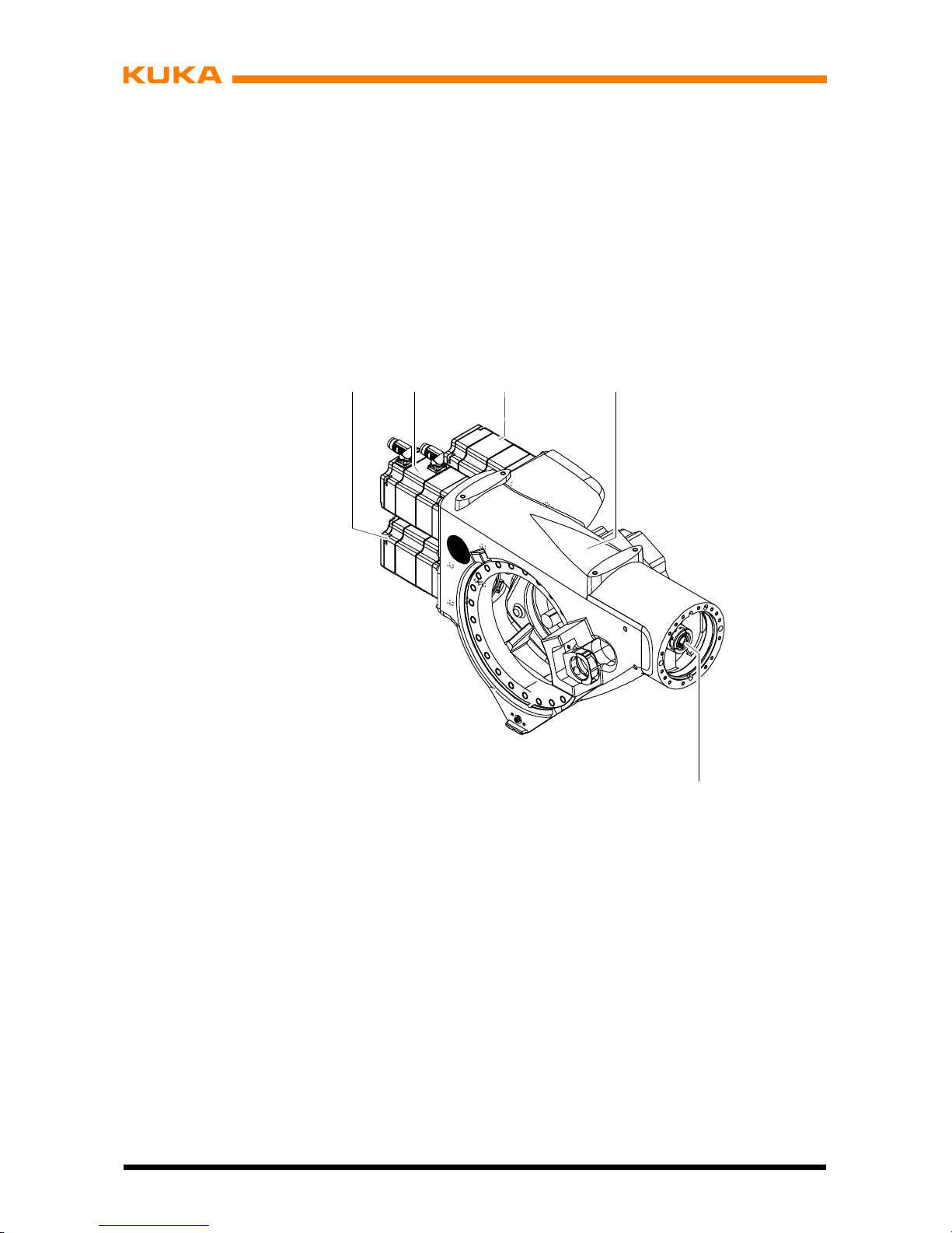
3.2 Wrist
The manipulator is equipped with a triple--axis in--line wrist (Fig. 2) for a payload of 30, 45
or 60 kg, depending on the type. The wrist is fastened onto the arm via the flange (4). The
axes 6, 5, 4 are driven by shafts (1, 2, 3). An end effector can be attached to the mounting
flange (5) of axis 6. Each axis has ameasuring device (6), through whichthe mechanical zero
of the respective axis can be checked by means ofan electronic probe (accessory) and transferred to the controller. For the direction of rotation of the axes, see Chapter 4, “Technical
Data”.
123
4
5
6
30/45/60 kg
1 Shaft 4 Flange
2 Shaft 5 Mounting flange
3 Shaft 6 Measuring device
Fig. 2 In-- line wrist

3 Product description (continued)
13 of 122
MA KR 30, 60 HA, KR C4 04.11.02 en
3.3 Arm
The arm assembly (Fig. 3/2) embodies the driven element of axis 3 of the manipulator. The
arm is flange--mounted to the side of the link arm (7) through a gear unit with integrated bearings and is driven by main axis motor unit A3 (6). The swivel axis (3) of the arm has been
so selected that with the rated payload there is no need for an additional counterweight to
balance the masses on the arm.
The effective software swivel range extends for all manipulators from +158° to --120°,referred to the electrical zero position of axis 3, which is given when the longitudinal axes of
the arm and link arm run parallel. The swivel range is limited by mechanical limit stops with
a buffer function in addition to the software limit switches.
Attached to the rear of the arm housing (8) are the motor units for wrist axes 4 to 6. Arm variants are available which are 200 mm (KR 60 L45 HA) or 400 mm (KR 60 L30 HA) longer than
the standard arm. These arm extensions involve a reduction in the rated payloads and the
individual axis speeds.
The arm housing consists -- as do the housings of the link arm and rotating column -- of a
light alloy construction optimized by means of CAD and FEM.
Mounted on the front end of the arm via a standardized interface is the in--line wrist (4), which
is driven by the wrist axis motor units (1) through push--on shafts (5) located inside the arm.
1 Motor units for wrist axes 6 Main axis motor unit A3
2Arm 7Linkarm
3 Rotational axis A3 8 Arm housing
4 In--line wrist
5 Shaft
123
567
8
4
Fig. 3 Arm
Assembly Instructions
14 of 122
MA KR 30, 60 HA, KR C4 04.11.02 en
3.3.1 Wrist axis motor units A4 to A6
The wrist axes are driven by three motor units. These are fastened to the arm (Fig. 4/4) by
means of screws. Motor units A4 (3) and A5 (1) are of the same design and drive the respective wrist axes via toothed belts and shafts. Wrist axis A6 is driven directly by motor unit
A6 (2) via a push--on shaft (5).
Each motor unit for the wrist axis drives consists of a brushless AC servomotor with apermanent--magnet single--disk brake and a hollow--shaft resolver (both integrated).
1 Motor unit A5
2 Motor unit A6
3 Motor unit A4
4Arm
5 Shaft
4
5
1
A4
A6
A5
23
Fig. 4 Wrist axis motor units A4 to A6

3 Product description (continued)
15 of 122
MA KR 30, 60 HA, KR C4 04.11.02 en
3.4 Link arm
The link arm (Fig. 5/1) is the driven element of axis 2. It pivots about rotational axis 2 (3)
through an effective software range from +35° to --135°⎯referred to the zero position of
axis 2, which corresponds to the horizontal position of the link arm in Fig. 5. The effective
software swivel range is limited by mechanical limit stops with a buffer function in addition
to the software limit switches.
1Linkarm
2 Main axis motor unit A2
3 Rotational axis 2
1
3
+35°
2
--135˚
Fig. 5 Link arm with turning range
The link arm (Fig. 6/6) houses gear unit A3 (2) at its upper end, and gear unit A2 (3) at its
lower end. The gear units (2, 3) are used both as drive elements and to support the arm and
link arm assemblies. The reference notch (1) and the gauge cartridge (4) are provided to define and locate the mechanical zero position of axes 2 and 3. The cables for energy supply
and signal transmission are routed in the interior of the link arm housing from the rotating
column to the arm.

Assembly Instructions
16 of 122
MA KR 30, 60 HA, KR C4 04.11.02 en
1 Reference notch A3 5 Rotational axis 2
2 Gear unit A3 6 Link arm
3 Gear unit A2 7 Rotational axis 3
4 Gauge cartridge A2
1
2
3
4
5
6
7
Fig. 6 Structure of link arm

3 Product description (continued)
17 of 122
MA KR 30, 60 HA, KR C4 04.11.02 en
3.4.1 Main axis motor units A1 to A3
The robot axes 1, 2 and 3 are driven by motor units as shown in Fig. 7. Each motor unit for
the main axis drives consists of a brushless AC servomotor (1) with a permanent--magnet
single--disk brake and hollow--shaft resolver (2), both integrated. The motor units for
axes 1, 2 and 3 are of the same design.
Axis 2 of the KR 60 is equipped with a more powerful motor unit.
1
2
2
1ACservomotor
2 Hollow--shaft resolver
Fig. 7 Motor unit for main axis drive

Assembly Instructions
18 of 122
MA KR 30, 60 HA, KR C4 04.11.02 en
3.5 Rotating column
The rotating column (Fig. 8/2) is the assembly located between the link arm and the base
frame. Screwed to the base frame (4) through a special reduction gear unit (3), which allows
it to rotate, it performs movements about rotational axis 1 (1). It has an effective software
turning range of 185° in both the (+) and (--) directions, measured from the zero position of
axis (6). This range is limited by mechanical limit stops with a buffer function in addition to
the software limit switches. This limit stop system operates with a trailing stop acting on both
sides, which is installed in the base frame and mechanically limits the large turning range of
185˚ in both directions.
1 Rotational axis 1
2 Rotating column
3 Special reduction gear unit
4Baseframe
5 Main axis motor unit A2
6 Zero position A1
6
5
--185°
+185°
2
3
4
1
Fig. 8 Rotating column with turning range (shown here: KR 30 HA)

3 Product description (continued)
19 of 122
MA KR 30, 60 HA, KR C4 04.11.02 en
The main axis motor unit for axis 1 (Fig. 9/3) is installed in the rotating column with a special
reduction gear unit (4), and the main axis motor unit for axis 2 (1) is mounted on the side of
the rotating column with its special reduction gear unit (2).
Part of the manipulator electrical installations is routed inside the rotating column.
1 Main axis motor unit A2
2 Special reduction gear unit A2
3 Main axis motor unit A1
4 Special reduction gear unit A1
1
4
2
3
Fig. 9 Structure of rotating column
3.6 Base frame
The base frame (Fig. 10) is the stationary part of the manipulator, on which the rotating column turns with the link arm, the arm and the wrist. Its base flange (5) features through-holes (4) for holding the manipulator down and twolocating boreholes (6), with which the manipulator can be placed on two locating pins (accessories, see Chapter 7, “Installation”).
Attached to a flange inside the base frame housing (3) is the special reduction gear unit (1)
of axis 1. Also integrated into this flange is the double--acting trailing stop, which together with
a stop block on the rotating column mechanically safeguards the software--limited movement
range of 370° about rotational axis 1.
In the base frame, the installation cables leading to the rotating column are routed stress-free about rotational axis 1 of the manipulator in a flexible tube. The space between the rotating column and the base frame is provided with two detachable, one--piece covers (2, 8).
The sockets for the connecting cables from the manipulator to the control cabinet are located
on the RDC box (10) and MFH (7).
The reference notch (11) necessary for determining the mechanical zero position is found
on the bracket (9).

Assembly Instructions
20 of 122
MA KR 30, 60 HA, KR C4 04.11.02 en
1 Special reduction gear unit A1 7 Junction box
2 Cover 8 Cover
3 Base frame housing 9 Bracket
4 Attachment holes (6x) 10 MFH, multi-- function housing
5 Base flange 11 Reference notch
6 Locating boreholes (2x)
1
2
3
4
6
7
5
88
9
11
10
Fig. 10 Structure of base frame
3.7 Working range limitation for A1 to A3
Mechanical stops for task--related limitation of the respective working range for axes 1 to 3
can be supplied as the “Working range limitation” accessory (see documentation “Working
Range Limitation”).
Axis 1: with two supplementary stops:
from +58° to +185° and --58° to --185°, adjustable in steps of 15°.
Axis 2: from +5° to +65° and --5° to --20°, adjustable in steps of 15°.
Axis 3: from +3° and --108° to --153° or --33° to --153°, adjustable in steps of 15°.

3 Product description (continued)
21 of 122
MA KR 30, 60 HA, KR C4 04.11.02 en
3.8 Working range monitoring for A1 and A2
Axes 1 and 2 can be equipped with position switches and slotted rings to which adjustable
cams are attached (see documentation “Working Range Monitoring”). This allows the position of the manipulator to be continuously monitored.
Up to three sectors of the movement range can be monitored on axis 1, and a maximum of
one sector on axis 2.
3.9 Energy supply system
For use in certain production technologies, the industrial robot can be equipped with an energy supply system installed between the base frame and axis 6. The energy supply system
consists of a dress package (cable and hose bundle) for transmitting the energy and fluids
typical for the specific application, and the “Group of holders for energy supply system” required for attaching it to the manipulator. The energy supply system accommodates the
cables and hoses and ensures that they are guided with minimum stress throughout the permitted working envelope. The design of the energy supply system is suitable for the majority
of applications in terms of reach and resistance to wear. There may, of course, be applications for which this version is of only limited use. A special version is required in such cases,
or a corresponding adaptation of the energy supply system.
The energy supply system is described in separate documentation.

Assembly Instructions
22 of 122
MA KR 30, 60 HA, KR C4 04.11.02 en

4 Technical data
23 of 122
MA KR 30, 60 HA, KR C4 04.11.02 en
4 Technical data
Information!
This description applies analogously to all of the industrial robots listed in Chapter 1,
regardless of the variant or model shown in the illustrations.
4.1 General
The industrial robots are six--axis manipulators for installation on the floor or on the ceiling.
They are suitable for all continuous--path controlled tasks. The main areas of applicationare:
-- Machining
-- Handling
-- Assembly
-- MIG/MAG welding
-- YAG laser beam welding
Notice!
Using the manipulator for purposes other than those mentioned above is consi-
dered contrary to its designated use (see Chapter 2, “Purpose”).
Fig. 11 shows the industrial robot with the manipulator (= robot arm and electrical installa-
tions) and the control cabinet.
The following data apply, unless otherwise indicated, to both floor--mounted and ceiling-mounted robots.

Assembly Instructions
24 of 122
MA KR 30, 60 HA, KR C4 04.11.02 en
1 Arm 5 Base frame
2 In--line wrist 6 Connecting cables
3 Link arm 7 Control cabinet (see
4 Rotating column separate documentation)
12
3
4
5
6
3
7
Fig. 11 Principal robot components

4 Technical data (continued)
25 of 122
MA KR 30, 60 HA, KR C4 04.11.02 en
4.2 Principal data
Type KR 30 HA
KR 60 HA
KR 60 L45 HA
KR 60 L30 HA
Number of axes 6 (Fig. 13)
Load limits see following table and Fig. 12
Robot type
KR 30 HA KR 60 HA
KR 60 L45
HA
KR 60 L30
HA
Wrist (IW)
1
IW 30/45/60 IW 30/45/60 IW 30/45/60 IW 30/45/60
Rated payload [kg] 30 60 45 30
Max. supplementary
load with rated payload
[kg]
35 35 35 35
Max. total load [kg] 65 95 80 65
1
IW = In--line wrist III
Payload
Max. total load
P
Suppl. load
Fig. 12 Load distribution
Axis data See the following table.
All specifications in the “Range of motion” column are referred to the electrical zero of the robot axis concerned.

Assembly Instructions
26 of 122
MA KR 30, 60 HA, KR C4 04.11.02 en
KR 30 HA
D In--line wrist, rated payload 30 kg
Axis
Range of motion,
software--limited
Speed
1 ±185˚ 140˚/s
2 +35˚
to
--135˚
126˚/s
3 +158˚
to
--120˚
140˚/s
4 ±350˚ 260˚/s
5 ±119˚ 245˚/s
6 ±350˚ 322˚/s
KR 60 HA
D In--line wrist, rated payload 60 kg
Axis
Range of motion,
software--limited
Speed
1 ±185˚ 128˚/s
2 +35˚
to
--135˚
102˚/s
3 +158˚
to
--120˚
128˚/s
4 ±350˚ 260˚/s
5 ±119˚ 245˚/s
6 ±350˚ 322˚/s
KR 60 L45 HA
D In--line wrist, rated payload 45 kg
Axis
Range of motion,
software--limited
Speed
1 ±185˚ 128˚/s
2 +35˚
to
--135˚
102˚/s
3 +158˚
to
--120˚
128˚/s
4 ±350˚ 260˚/s
5 ±119˚ 245˚/s
6 ±350˚ 322˚/s

4 Technical data (continued)
27 of 122
MA KR 30, 60 HA, KR C4 04.11.02 en
KR 60 L30 HA
D In--line wrist, rated payload 30 kg
Axis
Range of motion,
software--limited
Speed
1 ±185˚ 128˚/s
2 +35˚
to
--135˚
102˚/s
3 +158˚
to
--120˚
128˚/s
4 ±350˚ 260˚/s
5 ±119˚ 245˚/s
6 ±350˚ 322˚/s
A1
Fig. 13 Rotational axes and their directions of rotation

Assembly Instructions
28 of 122
MA KR 30, 60 HA, KR C4 04.11.02 en
Pose repeatability KR 30 HA ± 0.05 mm
(ISO 9283) KR 60 HA ± 0.05 mm
KR 60 L45 HA ± 0.05 mm
KR 60 L30 HA ± 0.05 mm
Mounting position floor, ceiling
Floor--mounted and ceiling--mounted manipulators must be
calibrated for the respective installation position.
Principal dimensions see Fig. 18 and Fig. 19.
Working envelope The shape and dimensions of the working envelope maybe
noted from Fig. 18 and Fig. 19.
Volume of working envelope KR 30 HA approx. 27.24 m
3
KR 60 HA approx. 27.24 m
3
KR 60 L45 HA approx. 36.89 m
3
KR 60 L30 HA approx. 47.78 m
3
The reference point is the intersection of axes 4 and 5.
Load center of gravity P seeFig.14toFig.16.
For the rated payload, the horizontal distance of the load
center of gravity P from the face of the mounting flange is
150 mm; the vertical distance from rotational axis 6 is
120 mm (nominal distance in each case).
Weight KR 30 HA approx. 665 kg
KR 60 HA approx. 665 kg
KR 60 L45 HA approx. 671 kg
KR 60 L30 HA approx. 679 kg
Principal dynamic loads See Fig. 21
Drive system Electromechanical, with transistor--controlled ACservomo-
tors.
Installed motor capacity approx. 14.9 kW
Protection classification of the robot
IP 64
ready for operation, with connecting cables plugged in
(according to EN 60529).
Protection classification of the in--line wrist
(standard) IP 65 (according to EN 60529)

4 Technical data (continued)
29 of 122
MA KR 30, 60 HA, KR C4 04.11.02 en
Ambient temperature during operation:
283 K to 328 K (+10 °Cto+55°C),
during storage/transportation:
233 K to 333 K (--40 °Cto+60°C).
Other temperature limits available on request.
Humidity class DIN EN 60721--3--3, Class 3K3
Sound level < 75 dB (A) outside the working envelope
(Fig. 18 and Fig. 19)
Color Manipulator
Manipulator overall: KUKA --Orange 2567
Motors: Black (RAL 9005)
Cover A1 Black (RAL 9005)
Plates seeFig.22toFig.30.
Special consumables none
Stopping distances and times
see separate documentation

Assembly Instructions
30 of 122
MA KR 30, 60 HA, KR C4 04.11.02 en
Notice!
Concerning Fig. 14 to Fig. 16:
These loading curves and the values in the table correspond to the maximum
load capacity. Both values (payload and principal moment of inertia) must be
checked in all cases. Exceeding this capacity will reduce the service life of the
robot and generally overload the motors and the gears; in any such case KUKA
must be consulted beforehand.
Information!
The values determined here are necessary for planning the application.
For commissioning the robot, additional input data are required in accordance with the
KUKA software documentation.
-- X
Lz
Lx
Ly
+X
-- Y
+Y
+Z
-- Z
Load center of gravity
Lxy
Lxy = Lx2+ Ly
2
Robot flange coordinate system
Permissible mass inertia at the
design point
(Lxy = 180 mm,
Lz = 150 mm)
9kgm
2
.
CAUTION: The mass inertia must be
verified using KUKA Load. It is
imperative for the load data to be
entered in the controller!
Lxy (mm)
100 200 300 400 500 700600
100
200
300
400
Lz (mm)
500
A4
A5
A6
KR 30 HA
KR 60 L30 HA
30 kg
27 kg
24 kg
21 kg
18 kg
15 kg
13 kg
Fig. 14 Load center of gravity P and loading curves for KR 30 HA; KR 60 L30 HA

4 Technical data (continued)
31 of 122
MA KR 30, 60 HA, KR C4 04.11.02 en
Information!
The values determined here are necessary for planning the application.
For commissioning the robot, additional input data are required in accordance with the
KUKA software documentation.
-- X
Lz
Lx
Ly
+X
-- Y
+Y
+Z
-- Z
Load center of gravity
Lxy
Lxy = Lx2+ Ly
2
Robot flange coordinate system
Permissible mass inertia at the
design point
(Lxy = 180 mm,
Lz = 150 mm)
18 kgm
2
.
CAUTION: The mass inertia must be
verified using KUKA Load. It is
imperative for the load data to be
entered in the controller!
Lxy (mm)
100 200 300 400 500 700600
100
200
300
400
Lz (mm)
500
A4
A5
A6
KR 60 HA
60 kg
55 kg
35 kg
50 kg
45 kg
40 kg
25 kg
30 kg
Fig. 15 Load center of gravity P and loading curves for KR 60 HA

Assembly Instructions
32 of 122
MA KR 30, 60 HA, KR C4 04.11.02 en
Information!
The values determined here are necessary for planning the application.
For commissioning the robot, additional input data are required in accordance with the
KUKA software documentation.
-- X
Lz
Lx
Ly
+X
-- Y
+Y
+Z
-- Z
Load center of gravity
Lxy
Lxy = Lx2+ Ly
2
Robot flange coordinate system
Permissible mass inertia at the
design point
(Lxy = 180 mm,
Lz = 150 mm)
13.5 kgm
2
.
CAUTION: The mass inertia must be
verified using KUKA Load. It is
imperative for the load data to be
entered in the controller!
Lxy (mm)
100 200 300 400 500 700600
100
200
300
400
Lz (mm)
500
A4
A5
A6
KR 60 L45 HA
45 kg
41 kg
37 kg
33 kg
29 kg
25 kg
21 kg
Fig. 16 Load center of gravity P and loading curves for KR 60 L45 HA

4 Technical data (continued)
33 of 122
MA KR 30, 60 HA, KR C4 04.11.02 en
Mounting flange DIN/ISO1mounting flange (Fig. 17). The mounting flange
is depicted with axes 4 and 6 in the zero position. The symbol
indicates the position of the locating element (bushing). M8 screws of grade 10.9 are to be used for attaching
payloads. The grip length of the screws in the flange must
be at least 1.5 x nominal diameter.
Depth of engagement: min. 12 mm
max. 14 mm
1
DIN/ISO 9409-- 1--A100
ø100
ø125
ø63
H7
170
to center A 4 / A 5
A
Section A -- A
A
X
m
Ø8H78 deep
Ø0.04
A
B
h8
Ø0.02
B
AB
M8 fastening screws,
grade 10.9
Depth of engagement: min. 12 mm
max. 14 mm
8.5
+0.3
0
7.5 ¦0.1
∅115 ¦0.05
12
Fig. 17 DIN/ISO mounting flange for in--line wrist 30/45/60 kg

Assembly Instructions
34 of 122
MA KR 30, 60 HA, KR C4 04.11.02 en
1218
1362
1446
180
150
2429
145
850
820, 1020, 1220 170
2498
1084
815
350
815
2230
2033
3003
983
2894
2695
3795
3398
868
1480
1281
NOTE: The supplementary load center of
gravity must be located as close as possible
to rotational axis 3 and to line a in Fig. 20.
The reference point for the working
envelope is the intersection of axes 4 and 5.
View Y, see Fig. 20.
IMPORTANT: The interferenceradius
(safe area) lies approx. 181 mm
beyond the reference point for the
working envelope.
Y
Fig. 18 Principal dimensions and working envelope (software values)

4 Technical data (continued)
35 of 122
MA KR 30, 60 HA, KR C4 04.11.02 en
--- 185˚
+185˚
R=181 mm
IMPORTANT: The interferenceradius
(safe area) lies approx. 181 mm
beyond the reference point for the
working envelope.
KR 30 HA R=2033
KR 60 HA R=2033
KR 60 L45 HA R=2230
KR 60 L30 HA R=2429
Fig. 19 Turning range A1

Assembly Instructions
36 of 122
MA KR 30, 60 HA, KR C4 04.11.02 en
View Y from Fig. 18
114
160
375
195
M8 (4x)
16 deep
Center A 3
82
Max. dimension for suppl. load
Support brackets for suppl. load (2x)
a
Fig. 20 Attachment holes for supplementary load

4 Technical data (continued)
37 of 122
MA KR 30, 60 HA, KR C4 04.11.02 en
Maximum load Normal load
F
v
= Vertical force F
vmax
= 13 600 N F
v normal
= 9 000 N
F
h
= Horizont force F
hmax
= 12 300 N F
h normal
= 6 950 N
M
k
= Tilting moment M
kmax
= 21 600 Nm M
k normal
= 11 900 Nm
M
r
= Turning moment about axis 1 M
rmax
= 18 400 Nm M
r normal
= 6 850 Nm
Total mass = robot + total load for type
665kg + 65kg KR30HA
665kg + 95kg KR60HA
671 kg + 80 kg KR 60 L45 HA
679 kg + 65 kg KR 60 L30 HA
F
v
F
h
M
k
M
r
F
v
The specified forces and moments already include the payload and the inertia force
(weight) of the manipulator.
Fig. 21 Principal loads acting on floor and ceiling due to robot and total load

Assembly Instructions
38 of 122
MA KR 30, 60 HA, KR C4 04.11.02 en
2
1
5
4
1
2
3
6
7
8
5
6
7
5
6
7
Fig. 22 Plates on robot (see also Fig. 23 to Fig. 30)
T ransportstellung:
T ransport position:
Position de transport:
A6
A5
A4A3A2A1
ATTENTION!WARNING!ACHTUNG!
D/GB/F
Vor dem Lösen der
Fundamentbefestigungsschrauben
muss der Roboter in
Transportstellung
gebracht werden!
The robot must be
in the transport
position before the
holding--down bolts
are slackened!
Le robot doit être
amené en position
de transport avant de
desserrer les boulons
de fixation des
fondations!
1
2xArtikel--Nr. 00 --118-- 545
0° --- 1 3 5 ° +158° +90°0°
Fig. 23 Transport position plate

4 Technical data (continued)
39 of 122
MA KR 30, 60 HA, KR C4 04.11.02 en
ATTENTION!WARNING!ACHTUNG!
Vor dem Entfernen des Motors Roboterachse
gegen Kippen sichern!
Only remove motor when robot axis is secured!
Avant démontage du moteur bloquer l’axe
concerné!
2
2x
D/GB/F
Artikel--Nr. 00 --118-- 545
Fig. 24 Instructions for safeguarding against toppling of A2 and A3
3
Typ e
Serial No.
XXXX kg
Baujahr
Poids
XXXXXXXXXXXXXXXXXXXXXXXXXX
Gewich t
No. d’articleArtikel--Nr.
Anneedefabric.
XXXXXXXXXXXXXXXXXXXXXXXXXXX
Serie--Nr.
XXXX--XX
Weight
Typ e
No. Se’rie#
$TRAFONAME[]=”#.....”
Article No.
XXXXXXXXXXXXXXXXXXXXXXXXXXX
Typ
Date
...\MADA\
XXXXXXXXX
XXXXXX
Traglast Load Charge
XXX kg
ReichweiteRange Portee
XXXX MM
^
^
^
de/en/fr
Roboter GmbH
Zugspitzstraße 14 0
86165 Augsburg.Germany
Fig. 25 Robot identification plate (example)

Assembly Instructions
40 of 122
MA KR 30, 60 HA, KR C4 04.11.02 en
Vor Aufstellung, Inbetriebnahme, Montage-- und
Wartungsarbeiten die Betriebsanleitung und
Sicherheitshinweise lesen und beachten!
Before installation, start--up, maintenance or
disassembling read and follow the safety
directions and operating instructions!
Avant installation, mise en service, réparation et
maintenance veuillez lire les châpitres
correspondants du manuel ainsi que les
consignes de sécurité et les respecter!
ATTENTION!WARNING!ACHTUNG!
D/GB/F
4
Artikel--Nr. 00 --118-- 545
Fig. 26 Reference to operating instructions
5
Fig. 27 High voltage warning sign
6
4x on each motor
Fig. 28 Hot surface warning sign

4 Technical data (continued)
41 of 122
MA KR 30, 60 HA, KR C4 04.11.02 en
.................
...........................................................
................................................
...........................................................
................................................
...........................................................
.................................................
On all motors.
7
Fig. 29 Drive motor rating plate
8
3x on base frame
00--104--232
Fig. 30 Danger zone

Assembly Instructions
42 of 122
MA KR 30, 60 HA, KR C4 04.11.02 en

5 Safety
43 of 122
MA KR 30, 60 HA, KR C4 04.11.02 en
5 Safety
5.1 Representation of warnings and notes
Safety
These warnings are relevant to safety and must be observed.
Danger!
These warnings mean that it is certain or highly probable that death or severe
injuries will occur, if no precautions are taken.
Warning!
These warnings mean that death or severe injuries may occur, if no precautions
are taken.
Caution!
These warnings mean that minor injuries may occur, if no precautions are taken.
Notice!
These warnings mean that damage to property may occur, if no precautions are
taken. They contain references to safety--relevant information or general safety
measures. These warnings do not refer to individual hazards or individual precautionary measures.
Information!
These hints serve to make your work easier or contain references to further information.
5.2 General
Notice!
This “Safety” chapter refers to a mechanical component of an industrial robot.
If the mechanical component is used together with a KUKA robot controller, the “Safety”
chapter of the operating instructions or assembly instructions of the robot controller
must be used!
This contains all the information provided in this “Safety” chapter. It also contains additional safety information relating to the robot controller which must be observed.
Where this “Safety” chapter uses the term “industrial robot”, this also refers to the individual mechanical component if applicable.

Assembly Instructions
44 of 122
MA KR 30, 60 HA, KR C4 04.11.02 en
5.2.1 Liability
The device described in this document is either an industrial robot or a component thereof.
Components of the industrial robot:
G Manipulator
G Robot controller
G Teach pendant
G Connecting cables
G External axes (optional), e.g. linear unit, turn--tilt table, positioner
G Software
G Options, accessories
The industrial robot isbuilt using state--of--the--art technology and in accordance with the recognized safety rules. Nevertheless, misuse of the industrial robot may constitute a risk to life
and limb or cause damage to the industrial robot and to other material property.
The industrial robot may only be used in perfect technical condition in accordance with its
intended use and only by safety--conscious persons who are fully aware of the risks involved
in its operation. Use of the industrial robot is subject to compliance with this document and
with the declaration of incorporation supplied together with the industrial robot. Any functional
disorders affecting the safety of the robot system must be rectified immediately .
Safety information
Safety information cannot be held against KUKA Roboter GmbH. Even if all safety instructions are followed, this is not a guarantee that the industrial robot will not cause personal injuries or material damage.
No modifications may be carried out to the industrial robot without the authorization of KUKA
Roboter GmbH. Additional components (tools, software, etc.), not supplied by KUKA Roboter GmbH, may be integrated into the industrial robot. The user is liable for any damage
these components may cause to the industrial robot or to other material property.
In addition to the Safety chapter, this document contains further safety instructions. These
must also be observed.
5.2.2 Intended use of the industrial robot
The industrial robot is intended exclusively for the use designated in the “Purpose” chapter
of the operating instructions or assembly instructions.
Information!
Further information is contained in the “Purpose” chapter of the operating instructions
or assembly instructions of the industrial robot.
Using the industrial robot for any other or additional purpose is considered impermissible
misuse. The manufacturer cannot beheld liable for any damageresulting from such use. The
risk lies entirely with the user.
Operating the industrial robot and its options within the limits of its intended use also involves
observance of the operating and assembly instructions for the individual components, with
particular reference to the maintenance specifications.

5 Safety (continued)
45 of 122
MA KR 30, 60 HA, KR C4 04.11.02 en
Misuse
Any use or application deviating from the intended use is deemed to be impermissible misuse.
This includes e.g.:
G Transportation of persons and animals
G Use as a climbing aid
G Operation outside the permissible operating parameters
G Use in potentially explosive environments
G Operation without additional safeguards
G Outdoor operation
G Underground operation
5.2.3 EC declaration of conformity and declaration of incorporation
This industrial robot constitutes partly completed machinery as defined by the EC Machinery
Directive. The industrial robot may only be put into operation if the following preconditions
are met:
G The industrial robot is integrated into a complete system.
Or: The industrial robot, together with other machinery, constitutes a complete system.
Or: All safety functions and safeguards required for operation in the complete machine
as defined by the EC Machinery Directive have been added to the industrial robot.
G The complete system complies with the EC Machinery Directive. This has been con-
firmed by means of an assessment of conformity.
Declaration of conformity
The system integrator must issue a declaration of conformity for the complete system in accordance with the Machinery Directive. The declaration of conformity forms the basis for the
CE mark for the system. The industrial robot must be operated in accordance with the applicable national laws, regulations and standards.
The robot controller is CE certified under the EMC Directive and the Low Voltage Directive.
Declaration of incorporation
The industrial robot as partly completed machinery is supplied with a declaration of
incorporation in accordance with Annex II B of the EC Machinery Directive 2006/42/EC. The
assembly instructions and a list of essential requirements complied with in accordance with
Annex I are integral parts of this declaration of incorporation.
The declaration of incorporation declares that the start--up of the partly completed machinery
remains impermissible until the partly completed machinery has been incorporated into machinery, or has been assembled with other parts to form machinery, and this machinery complies with the terms of the EC Machinery Directive, and the EC declaration of conformity is
present in accordance with Annex II A.
The declaration of incorporation, together with its annexes, remains with the system integrator as an integral part of the technical documentation of the complete machinery.

Assembly Instructions
46 of 122
MA KR 30, 60 HA, KR C4 04.11.02 en
5.2.4 Terms used
Term Description
Axis range Range of each axis, in degrees or millimeters, within which it may
move. The axis range must be defined for each axis.
Stopping distance Stopping distance = reaction distance + braking distance
The stopping distance is part of the danger zone.
Workspace The manipulator is allowed to move within its workspace. The work-
space is derived from the individual axis ranges.
Operator (User) The user of the industrial robot can be the management, employer or
delegated person responsible for use of the industrial robot.
Danger zone The danger zone consists of the workspace and the stopping dis-
tances.
Service life The service life of a safety--relevant component begins at the time of
delivery of the component to the customer.
The service life is not affected by whether the component is used in a
robot controller or elsewhere or not, as safety--relevant components are
also subject to ageing during storage.
KCP KUKA Control Panel
Teach pendant for the KR C2/KR C2 edition 2005
The KCP has all the operator control and display functions required for
operating and programming the industrial robot.
KCP smartPAD see “smartPAD”
Manipulator The robot arm and the associated electrical installations.
Protected space The safety zone is situated outside the danger zone.
smartPAD Teach pendant for the KR C4
The smartPAD has all the operator control and display functions
required for operating and programming the industrial robot.
Stop category 0 The drives are deactivated immediately and the brakes are applied.
The manipulator and any external axes (optional) perform path--oriented braking.
Note: This stop category is called STOP 0 in this document.
Stop category 1 The manipulator and any external axes (optional) perform path--main-
taining braking. The drives are deactivated after 1 s and the brakes are
applied.
Note: This stop category is called STOP 1 in this document.
Stop category 2 The drives are not deactivated and the brakes are not applied. The ma-
nipulator and any external axes (optional) are braked with a normal
braking ramp.
Note: This stop category is called STOP 2 in this document.
System integrator
(plant integrator)
System integrators are people who safely integrate the industrial robot
into a complete system and commission it.
T1 Test mode, Manual Reduced Velocity (<= 250 mm/s)
T2 Test mode, Manual High Velocity (> 250 mm/s permissible)
External axis Motion axis which is not part of the manipulator but which is controlled
using the robot controller, e.g. KUKA linear unit, turn--tilt table, Posiflex.

5 Safety (continued)
47 of 122
MA KR 30, 60 HA, KR C4 04.11.02 en
5.3 Personnel
The following persons or groups of persons are defined for the industrial robot:
G User
G Personnel
Notice!
All persons working with the industrial robot must have read and understood
the industrial robot documentation, including the safety chapter.
User
The user must observe the labor laws and regulations.
This includes e.g.:
G The user must comply with his monitoring obligations.
G The user must carry out instructions at defined intervals.
Personnel
Personnel must be instructed, before any work is commenced, in the type of work involved
and what exactly it entails as well as any hazards which may exist. Instruction must be carried
out regularly. Instruction is also required after particular incidents or technical modifications.
Personnel includes:
G System integrator
G Operators, subdivided into:
-- Start--up, maintenance and service personnel
-- Operating personnel
-- Cleaning personnel
Notice!
Installation, exchange, adjustment, operation, maintenance and repair must be
performed only as specified in the operating or assembly instructions for the
relevant component of the industrial robot and only by personnel specially
trained for this purpose.
System integrator
The industrial robot is safely integrated into a complete system by the system integrator.
The system integrator is responsible for the following tasks:
G Installing the industrial robot
G Connecting the industrial robot
G Performing risk assessment
G Implementing the required safety functions and safeguards
G Issuing the declaration of conformity
G Attaching the CE mark
G Creating the operating instructions for the complete system

Assembly Instructions
48 of 122
MA KR 30, 60 HA, KR C4 04.11.02 en
Operator
The operator must meet the following preconditions:
G The operator must be trained for the work to be carried out.
G Work on the industrial robot must only be carried out by qualified personnel. These are
people who, due to their specialist training, knowledge and experience, and their familiarization with the relevant standards, are able to assess the work to be carried out and
detect any potential hazards.
Example
The tasks can be distributed as shown in the following table:
Tasks Operating
personnel
Programmer System
integrator
Switch robot controller
on/off
x x x
Start program x x x
Select program x x x
Select operating mode x x x
Calibration (tool, base) x x
Master the manipulator x x
Configuration x x
Programming x x
Commissioning x
Maintenance x
Repair x
Decommissioning x
Transportation x
Notice!
Work on the electrical and mechanical equipment of the industrial robot may
only be carried out by specially trained personnel.
5.4 Workspace, safety zone and danger zone
Working zones are to be restricted to the necessary minimum size. A workspace must be
safeguarded using appropriate safeguards.
The safeguards (e.g. safety gate) must be situated inside the safety zone. In the case of a
stop, the manipulator and external axes (optional) are braked and come to a stop within the
danger zone.
The danger zone consists of the workspace and the stopping distances of the manipulator
and external axes (optional). It must be safeguarded by means of physical safeguards to prevent danger to persons or the risk of material damage.

5 Safety (continued)
49 of 122
MA KR 30, 60 HA, KR C4 04.11.02 en
(1) Workspace
(2) Manipulator
(3) Stopping distance
(4) Safety zone
Fig. 31 Example: axis range A1
5.5 Overview of protective equipment
The protective equipment of the mechanical component may include:
G Mechanical end stops
G Mechanical axis range limitation (optional)
G Axis range monitoring (optional)
G Release device (optional)
G Labeling of danger areas
Not all equipment is relevant for every mechanical component.
5.5.1 Mechanical end stops
Depending on the robot variant, the axis rangesof the main andwrist axes of the manipulator
are partially limited by mechanical end stops.
Additional mechanical end stops can be installed on the external axes.
Notice!
If the manipulator or an external axis hits an obstruction or a mechanical end
stop or axis range limitation, this can result in material damage to the industrial
robot. The manipulator must be taken out of operation and KUKA Roboter GmbH
must be consulted before it is put back into operation.

Assembly Instructions
50 of 122
MA KR 30, 60 HA, KR C4 04.11.02 en
5.5.2 Mechanical axis range limitation (optional)
Some manipulators can be fitted with mechanical axis range limitation in axes A1 to A3. The
adjustable axis range limitation systems restrict the working range to the required minimum.
This increases personal safety and protection of the system.
In the case of manipulators that are not designed to be fitted with mechanical axis range limitation, the workspace must be laid out in such a way that there is no danger to persons or
material property, even in the absence of mechanical axis range limitation.
If this is not possible, the workspace must be limited by means of photoelectric barriers, photoelectric curtains or obstacles on the system side. There must be no shearing or crushing
hazards at the loading and transfer areas.
Information!
This option is not available for all robot models. Information on specific robot models
can be obtained from KUKA Roboter GmbH.
5.5.3 Axis range monitoring (optional)
Some manipulators can be fitted with dual--channel axis range monitoring systems in main
axes A1 to A3. The positioner axes may be fitted with additional axis range monitoring systems. The safety zone for an axis can be adjusted and monitored using an axis range monitoring system. This increases personal safety and protection of the system.
Information!
This option is not available for all robot models and not for the KR C4. Information on
specific robot models can be obtained from KUKA Roboter GmbH.
5.5.4 Options for moving the manipulator without drive energy
Caution!
The system user is responsible for ensuring that the training of personnel with
regard to the response to emergencies or exceptional situations also includes
how the manipulator can be moved without drive energy.
Description
The following devices are available for moving the manipulator after an accident or malfunction:
G Release device (optional)
The release device can be used for the main axis drive motors and, depending on the
robot variant, also for the wrist axis drive motors.
G Brake release device (optional)
The brake release device is designed for robot variants whose motors are not freely
accessible.
G Moving the wrist axes directly by hand
There is no release device available for the wrist axes of variants in the low payload
category. This is not necessary because the wrist axes can be moved directly by hand.

5 Safety (continued)
51 of 122
MA KR 30, 60 HA, KR C4 04.11.02 en
Information!
Information about the options available for the various robot models and about how to
use them can be found in the assembly and operating instructions for the robot or requested from KUKA Roboter GmbH.
Notice!
Moving the manipulator without drive energy can damage the motor brakes of
the axes concerned. The motor must be replaced if the brake has been damaged.
The manipulator may therefore be moved without drive energy only in emergencies or exceptional situations, e.g. for rescuing persons.

Assembly Instructions
52 of 122
MA KR 30, 60 HA, KR C4 04.11.02 en
5.5.5 Labeling on the industrial robot
All plates, labels, symbols and marks constitute safety--relevant parts of the industrial robot.
They must not be modified or removed.
Labeling on the industrial robot consists of:
G Identification plates
G Warning labels
G Safety symbols
G Designation labels
G Cable markings
G Rating plates
Information!
Further information is contained in the technical data of the operating instructions or
assembly instructions of the components of the industrial robot.
5.6 Safety measures
5.6.1 General safety regulations
The industrial robot may only be used in perfect technical condition in accordance with its
intended use and only by safety--conscious persons. Operator errors can result in personal
injury and damage to property.
It is important to be prepared for possible movements of the industrial robot even after the
robot controller has beenswitched off andlocked. Incorrect installation (e.g. overload) or mechanical defects (e.g. brake defect) can cause the manipulator or external axes to sag. If
work is to be carried out on a switched--off industrial robot, the manipulator and external axes
must first be moved into a position in which they are unable to move on their own, whether
the payload is mounted or not. If this is not possible, the manipulator and external axes must
be secured by appropriate means.
Danger!
In the absence of operational safety functions and safeguards, the industrial
robot can cause personal injury or material damage. If safety functions or
safeguards are dismantled or deactivated, the industrial robot may not be
operated.
Danger!
Standing underneath the robot arm can cause death or serious injuries. For this
reason, standing underneath the robot arm is prohibited!
Caution!
The motors reach temperatures during operation which can cause burns to the
skin. Contact must be avoided. Appropriate safety precautions must be taken,
e.g. protective gloves must be worn.

5 Safety (continued)
53 of 122
MA KR 30, 60 HA, KR C4 04.11.02 en
KCP/smartPAD
The user must ensure that the industrial robot is only operated with the KCP/smartPAD by
authorized persons.
If more than one KCP/smartPAD is used in the overall system, it must be ensured that each
device is unambiguously assigned to the corresponding industrial robot. They must not be
interchanged.
Warning!
The operator must ensure that decoupled KCPs/smartPADs are immediately
removed from the system and stored out of sight and reach of personnel
working on the industrial robot. This serves to prevent operational and
non--operational EMERGENCY STOP devices from becoming interchanged.
Failure to observe this precaution may result in death, severe injuries or
considerable damage to property.
External keyboard, external mouse
An external keyboard and/or external mouse may only be used if the following conditions are
met:
G Start--up or maintenance work is being carried out.
G The drives are switched off.
G There are no persons in the danger zone.
The KCP/smartPAD must not be used as long as an external keyboard and/or external
mouse are connected to the control cabinet.
The external keyboard and/or external mouse must be removed from the control cabinet as
soon as the start--up or maintenance work is completed or the KCP/smartPAD is connected.
Modifications
After modifications to the industrial robot, checks must be carried out to ensure the required
safety level. The valid national or regional work safety regulations must be observed for this
check. The correct functioning of all safety circuits must also be tested.
New or modified programs must always be tested first in Manual Reduced Velocity mode
(T1).
After modifications to the industrial robot, existing programs must always be tested first in
Manual Reduced Velocity mode (T1). This applies to all components of the industrial robot
and includes modifications to the software and configuration settings.
Faults
The following tasks must be carried out in the case of faults in the industrial robot:
G Switch off the robot controller and secure it (e.g. with a padlock) to prevent unauthorized
persons from switching it on again.
G Indicate the fault by means of a label with a corresponding warning (tagout).
G Keep a record of the faults.
G Eliminate the fault and carry out a function test.

Assembly Instructions
54 of 122
MA KR 30, 60 HA, KR C4 04.11.02 en
5.6.2 Transportation
Manipulator
The prescribed transport position of the manipulator must be observed. Transportation must
be carried out in accordance with the operating instructions or assembly instructions of the
robot.
Robot controller
The prescribed transport position of the robot controller must be observed. Transportation
must be carried out in accordance with the operating instructions or assembly instructions
of the robot controller.
Avoid vibrations and impacts during transportation in order to prevent damage to the robot
controller.
External axis (optional)
The prescribed transport position of the external axis (e.g. KUKA linear unit, turn--tilt table,
etc.) must be observed. Transportation must be carried out in accordance with the operating
instructions or assembly instructions of the external axis.
5.6.3 Start--up and recommissioning
Before starting up systems and devices for the first time, a check must be carried out to ensure that the systems and devices are complete and operational, that they can be operated
safely and that any damage is detected.
The valid national or regional work safety regulations must be observed for this check. The
correct functioning of all safety circuits must also be tested.
Notice!
The passwords for logging onto the KUKA System Software as “Expert” and
“Administrator” must be changed before start--up and must only be communicated to authorized personnel.
Danger!
The robot controller is preconfigured for the specific industrial robot. If cables
are interchanged, the manipulator and the external axes (optional) may receive
incorrect data and can thus cause personal injury or material damage. If a system consists of more than one manipulator, always connect the connecting
cables to the manipulators and their corresponding robot controllers.
Notice!
If additional components (e.g. cables), which are not part of the scope of supply
of KUKA Roboter GmbH, are integrated into the industrial robot, the user is responsible for ensuring that these components do not adversely affect or disable
safety functions.
Notice!
If the internal cabinet temperature of the robot controller differs greatly from the
ambient temperature, condensation can form, which may cause damage to the
electrical components. Do not put the robot controller into operation until the
internal temperature of the cabinet has adjusted to the ambient temperature.

5 Safety (continued)
55 of 122
MA KR 30, 60 HA, KR C4 04.11.02 en
Function test
The following tests must be carried out before start--up and recommissioning.
It must be ensured that:
G The industrial robot is correctly installed and fastened in accordance with the specifica-
tions in the documentation.
G There are no foreign bodies or loose parts on the industrial robot.
G All required safety equipment is correctly installed and operational.
G The power supply ratings of the industrial robot correspond to the local supply voltage
and mains type.
G The ground conductor and the equipotential bonding cable are sufficiently rated and
correctly connected.
G The connecting cables are correctly connected and the connectors are locked.
Machine data
It must be ensured that the rating plate on the robot controller has the same machine data
as those entered in the declaration of incorporation.
The machine data on the rating plate of the manipulator and the external axes (optional) must
be entered during start--up.
Danger!
The industrial robot must not be moved if incorrect machine data are loaded.
Death, severe injuries or considerable damage to property may otherwise result.
The correct machine data must be loaded.
5.6.4 Manual mode
Manual mode is the mode for setup work. Setup work is all the tasks that have to be carried
out on the industrial robot to enable automatic operation. Setup work includes:
G Jog mode
G Teach
G Programming
G Program verification
The following must be taken into consideration in manual mode:
G If the drives are not required, they must be switched off to prevent the manipulator or
the external axes (optional) from being moved unintentionally.
New or modified programs must always be tested first in Manual Reduced Velocity
mode (T1).
G The manipulator, tooling or external axes (optional) must never touch or project beyond
the safety fence.
G Workpieces, tooling and other objects must not become jammed as a result of the in-
dustrial robot motion, nor must they lead to short--circuits or be liable to fall off.
G All setup work must be carried out, where possible, from outside the safeguarded area.

Assembly Instructions
56 of 122
MA KR 30, 60 HA, KR C4 04.11.02 en
If the setup work has to be carried out inside the safeguarded area, the following must be
taken into consideration:
In Manual Reduced Velocity mode (T1):
G If it can be avoided, there must be no other persons inside the safeguarded area.
If it is necessary for there to be several persons inside the safeguarded area, the
following must be observed:
-- Each person must have an enabling device.
-- All persons must have an unimpeded view of the industrial robot.
-- Eye--contact between all persons must be possible at all times.
G The operator must be so positioned that he can see into the danger area and get out
of harm’s way .
In Manual High Velocity mode (T2):
G This mode may only be used if the application requires a test at a velocity higher than
Manual Reduced Velocity.
G Teaching and programming are not permissible in this operating mode.
G Before commencing the test, the operator must ensure that the enabling devices are
operational.
G The operator must be positioned outside the danger zone.
G There must be no other persons inside the safeguarded area. It is the responsibility of
the operator to ensure this.
5.6.5 Automatic mode
Automatic mode is only permissible in compliance with the following safety measures:
G All safety equipment and safeguards are present and operational.
G There are no persons in the system.
G The defined working procedures are adhered to.
If the manipulator or an external axis (optional) comes to a standstill for no apparent reason,
the danger zone must not be entered until an EMERGENCY STOP has been triggered.
5.6.6 Maintenance and repair
After maintenance and repair work, checks must be carried out to ensure the required safety
level. The valid national or regional work safety regulations must be observed for this check.
The correct functioning of all safety circuits must also be tested.
The purpose of maintenance and repair work is to ensure that the system is kept operational
or, in the event of a fault, to return the system to an operational state. Repair work includes
troubleshooting in addition to the actual repair itself.
The following safety measures must be carried out when working on the industrial robot:
G Carry out work outside the danger zone. If work inside the danger zone is necessary,
the user must define additional safety measures to ensure the safe protection of personnel.
G Switch off the industrial robot and secure it (e.g. with a padlock) to prevent it from being
switched on again. If it is necessary to carry out work with the robot controller switched
on, the user must define additional safety measures to ensure the safe protection of
personnel.
G If it is necessary to carry out work with the robot controller switched on, this may only
be done in operating mode T1.

5 Safety (continued)
57 of 122
MA KR 30, 60 HA, KR C4 04.11.02 en
G Label the system with a sign indicating that work is in progress. This sign must remain
in place, even during temporary interruptions to the work.
G The EMERGENCY STOP systems must remain active. If safety functions or safe-
guards are deactivated during maintenance or repair work, they must be reactivated
immediately after the work is completed.
Warning!
Before work is commenced on live parts of the robot system, the main switch
must be turned off and secured against being switched on again by unauthorized personnel. The incoming power cable must be deenergized. The robot controller and mains supply lead must then be checked to ensure that it is deenergized.
If the KR C4 or VKR C4 robot controller is used:
It is not sufficient, before commencing work on live parts, to execute an EMERGENCY STOP or a safety stop, or to switch off the drives, as this does not disconnect the robot system from the mains power supply in the case of the drives
of the new generation. Parts remain energized. Death or severe injuries may result.
Faulty components must be replaced using new components with the same article numbers
or equivalent components approved by KUKA Roboter GmbH for this purpose.
Cleaning and preventive maintenance work is to be carried out inaccordance with the operating instructions.
Robot controller
Even when the robot controller is switched off, parts connected to peripheral devices may
still carry voltage. The external power sources must therefore be switched off if work is to
be carried out on the robot controller.
The ESD regulations must be adhered to when working on components in the robot controller.
Voltages in excess of 50 V (up to 600 V) can be present in various components for several
minutes after the robot controller has been switched off! To prevent life--threatening injuries,
no work may be carried out on the industrial robot in this time.
Water and dust must be prevented from entering the robot controller.
Counterbalancing system
Some robot variants are equipped with a hydropneumatic, spring or gas cylinder counterbalancing system.
The hydropneumatic and gas cylinder counterbalancing systems are pressure equipment
and, as such, are subject to obligatory equipment monitoring. Depending on the robot variant, the counterbalancing systems correspond to category 0, II or III, fluid group 2, of the
Pressure Equipment Directive.
The user must comply with the applicable national laws, regulations and standards pertaining
to pressure equipment.
Inspection intervals in Germany in accordance with Industrial Safety Order, Sections 14 and
15. Inspection by the user before commissioning at the installation site.
The following safety measures must be carried out when working on the counterbalancing
system:
G The manipulator assemblies supported by the counterbalancing systems must be se-
cured.
G Work on the counterbalancing systems must only be carried out by qualified personnel.

Assembly Instructions
58 of 122
MA KR 30, 60 HA, KR C4 04.11.02 en
Hazardous substances
The following safety measures must be carried out when handling hazardous substances:
G Avoid prolonged and repeated intensive contact with the skin.
G Avoid breathing in oil spray or vapors.
G Clean skin and apply skin cream.
Notice!
To ensure safe use of our products, we recommend that our customers regularly
request up--to--date safety data sheets from the manufacturers of hazardous substances.
5.6.7 Decommissioning, storage and disposal
The industrial robot must be decommissioned, stored and disposed of in accordance with
the applicable national laws, regulations and standards.

5 Safety (continued)
59 of 122
MA KR 30, 60 HA, KR C4 04.11.02 en
5.7 Applied norms and regulations
Name Definition Edition
2006/42/EC
Machinery Directive:
Directive 2006/42/EC of the European Parliament and of
the Council of 17 May 2006 on machinery, and amending
Directive 95/16/EC (recast)
2006
2004/108/EC
EMC Directive:
Directive 2004/108/EC of the European Parliament and of
the Council of 15 December 2004 on the approximation of
the laws of the Member States relating to electromagnetic
compatibility and repealing Directive 89/336/EEC
2004
97/23/EC
Pressure Equipment Directive:
Directive 97/23/EC of the European Parliament and of the
Council of 29 May 1997 on the approximation of the laws
of the Member States concerning pressure equipment
(Only applicable for robots with hydropneumatic counterbalancing system.)
1997
EN ISO 13850
Safety of machinery:
Emergency stop -- Principles for design
2008
EN ISO 13849--1
Safety of machinery:
Safety--related parts of control systems;
Part 1: General principles of design
2008
EN ISO 13849--2
Safety of machinery:
Safety--related parts of control systems;
Part 2: Validation
2008
EN ISO 12100
Safety of machinery:
General principles of design, risk assessment and risk reduction
2010
EN ISO 10218--1
Industrial robots: Safety
201 1
EN 614--1
Safety of machinery:
Ergonomic design principles -- Part 1: Terms and general
principles
2006
EN 61000--6--2
Electromagnetic compatibility (EMC):
Part 6--2: Generic standards; Immunity for industrial environments
2005
EN 61000--6--4
Electromagnetic compatibility (EMC):
Part 6--4: Generic standards; Emission standard for industrial environments
2007
EN 60204--1
Safety of machinery:
Electrical equipment of machines
Part 1: General requirements
2006

Assembly Instructions
60 of 122
MA KR 30, 60 HA, KR C4 04.11.02 en

6 Transportation
61 of 122
MA KR 30, 60 HA, KR C4 04.11.02 en
6 Transportation
Information!
This description applies analogously to all of the industrial robots listed in Chapter 1,
regardless of the variant or model shown in the illustrations.
Caution!
If the manipulator is transported by fork lift truck, the forks must be placed in the
fork slots. It is forbidden to pick up the manipulator in any other way using a
fork lift truck!
The fork lift truck, lifting tackle and crane must be suitable for handling the
manipulator. For weight, see Chapter 4, “Technical data”.
The manipulator must be moved into its transport position each time it is
transported. It must be ensured that the manipulator is stable while it is being
transported.
The manipulator must remain in its transport position until it is -- depending on
the type -- fastened to the floor or to the ceiling.
Before the manipulator is lifted, it must be ensured that it is free from
obstructions. Transport safeguards, such as nails and screws, are all to be
removed in advance, as is any rust or glue on contact surfaces.
The most important factor in deciding on the method of transportation is the installation position of the manipulator.
The manipulator can be transported as follows:
G With lifting tackle and crane (Fig. 34, left--hand side)
The manipulator can be suspended from the hook of a crane by means of lifting tackle attached to three M16 DIN 580 eyebolts on the rotating column.
Caution!
The ropes or belts of the lifting tackle must be positioned so that there is no
possibility of the manipulator tilting to the side and of cabling or connectors
being damaged.
Caution!
Only approved handling equipment and lifting tackle with an adequate carrying
capacity may be used for transporting the manipulator.
For the weight of the manipulator, see Chapter 4, “Technical data”.
All three M16 DIN 580 eyebolts on the rotating column must always be used to
suspend the manipulator.

Assembly Instructions
62 of 122
MA KR 30, 60 HA, KR C4 04.11.02 en
1
Fig. 32 Transport position
G With fork lift truck (Fig. 34, right--hand side)
Caution!
If the manipulator is transported by fork lift truck, the forks must be placed in the
fork slots. It is forbidden to pick up the manipulator in any other way using a
fork lift truck!
200
663
568
87.4
792
560
100
187.4
622
721
1)
688
1
2
31
122.5
27
117.5
2
1) KR 60 HA
KR 60 L30 HA
KR 60 L45 HA
Fig. 33 Fork slots
For transport with a fork lift truck, two removable, open--ended fork slots (Fig. 33/2) are
mounted on the rotating column. This allows the manipulator (1) to be picked up from two
sides.
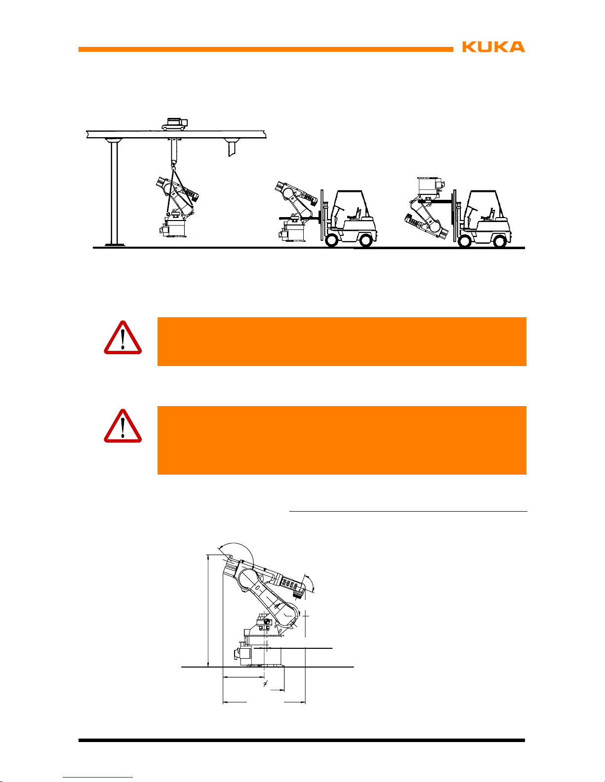
6 Transportation (continued)
63 of 122
MA KR 30, 60 HA, KR C4 04.11.02 en
Fig. 34 Transporting floor--mounted and ceiling--mounted manipulators
If the manipulator is to be transported away from its site of operation, the following is to be
observed:
Warning!
Turn the main switch on the robot control cabinet to “OFF” and secure it with a
padlock to prevent unauthorized persons from switching it on again.
(1) Remove tools and additional devices should they prevent the transport position from
being reached or generally impede transportation.
Warning!
Before performing the next step, it must be ensured that it is not possible for
anyone to be injured within the range of the slowly moving manipulator.
The manipulator may only be moved at jog speed, with all applicable safety rules
and regulations being observed.
(2) Put the robot into operation and move it into the transport position (Fig. 35, Fig. 36)*.
A1 A2 A3 A4 A5 A6
0˚
---135˚ +155˚ 0˚ +90˚ 0˚*
* All angles are specified relative to the electrical
“zero position” or to the KCP display.
KR 30, 60 HA,
1)
without arm extension
2)
200 mm arm extension
3)
400 mm arm extension
659
643
1793
155°
135°
1309
1)
1498
2)
1685
3)
241)382)85
3)

Assembly Instructions
64 of 122
MA KR 30, 60 HA, KR C4 04.11.02 en
Fig. 35 Transport position for floor--mounted manipulators
* All angles are specified relative to the electrical
“zero position” or to the KCP display.
KR 30, 60 HA,
1)
without arm extension
2)
200 mm arm extension
3)
400 mm arm extension
659
643
1793
155°
135°
1309
1)
1498
2)
1685
3)
241)382)85
3)
Fig. 36 Transport position for ceiling--mounted manipulators
Warning!
Turn the main switch on the robot control cabinet to “OFF” and secure it with a
padlock to prevent unauthorized persons from switching it on again.
For further work steps, see Chapter 7, “Installation, connection, exchange”.

7 Installation, connection
65 of 122
MA KR 30, 60 HA, KR C4 04.11.02 en
7 Installation, connection
Information!
This description applies analogously to all of the industrial robots listed in Chapter 1,
regardless of the variant or model shown in the illustrations.
7.1 General
Caution!
Observe Chapter 5, “Safety”!
With all work involving the connection of the manipulator (and of the control
cabinet), the control cabinet documentation “Initial Start--up” must be observed.
Notice!
When putting the manipulator into operation either for the first time or after an
exchange, zero adjustment must be carried out in accordance with the Operating
Handbook, Software KR C4, Chapter “Start-- up”, Section “Mastering/Unmastering”.
Caution!
If the manipulator is transported by fork lift truck, the forks must be placed in the
fork slots. It is forbidden to pick up the manipulator in any other way using a
fork lift truck!
The fork lift truck, lifting tackle and crane must be suitable for handling the
manipulator. For weight, see Chapter 4, “Technical data”.
The manipulator must be moved into its transport position each time it is
transported. It must be ensured that the manipulator is stable while it is being
transported.
The manipulator must remain in its transport position until it is -- depending on
the type -- fastened to the floor, the ceiling or to a hinged steel base.
Before the manipulator is lifted, it must be ensured that it is free from
obstructions. Transport safeguards, such as nails and screws, are all to be
removed in advance, as is any rust or glue on contact surfaces.
Before any installation and exchange work is started, any attached tools or additional equipment that would hinder the installation and exchange work must be dismounted.
The description of the installation and exchange operations is subdivided into job steps with
numbers in brackets appearing before them. The text which immediately follows these steps
must also be read if it is specially marked by a warning triangle or either of the hand sym-
bols. This is because many of these marked texts refer to the preceding job
step.

Assembly Instructions
66 of 122
MA KR 30, 60 HA, KR C4 04.11.02 en
Example:
(8) Lower the manipulator slowly without tilting it.
Notice!
The manipulator must be lowered vertically downwards until both locating pins
are free.
Some of the specially marked texts refer exclusively to everything that follows
-- until the in-
struction is expressly revoked or the work is completed at the end of a section.
Example:
Warning!
Turn main switch on the manipulator control cabinet to “OFF” and secure it with
a padlock to prevent unauthorized persons from switching it on again.
Warning!
If it is necessary to carry out work in the area beneath
a manipulator, the latter
must be secured to guard against the risk of unintended motion into this area.
This can be done by supporting it from below or by securing it with a rope from
above.
Never work or stand under suspended loads!
7.2 Information for planning
In the planning and design phase, care must be taken regarding the functions or applications
to be executed by the kinematic system. The following conditions can lead to premature
wear. They necessitate shorter maintenance intervals and/or earlier exchange of components. In addition, the permissible operating parameters specified in the technical data must
be taken into account during planning.
G Continuous operation near temperature limits or in abrasive environments.
G Continuous operation close to the performance limits, e.g. high rpm of an axis.
G High duty cycle of individual axes.
G Monotonous motion profiles, e.g. short, frequently recurring axis motions.
G Static axis positions, e.g. continuous vertical position of a wrist axis.
If one or more of these conditions are to apply during operation of the kinematic system,
KUKA Roboter GmbH must be consulted.

7 Installation, connection (continued)
67 of 122
MA KR 30, 60 HA, KR C4 04.11.02 en
7.3 Principal loads
Forces occur during operation of the manipulator which must be safely transmitted to the
floor or ceiling. The forces that have to be taken into account are specified in Fig. 37. The
data given in the illustration can also be used as a basis for more extensive static investigations.
The specified forces and moments already include the payload and the inertia force (weight)
of the manipulator.
Maximum load Normal load
F
v
= Vertical force F
vmax
= 13 600 N F
v normal
= 9 000 N
F
h
= Horizont force F
hmax
= 12 300 N F
h normal
= 6 950 N
M
k
= Tilting moment M
kmax
= 21 600 Nm M
k normal
= 11 900 Nm
M
r
= Turning moment about axis 1 M
rmax
= 18 400 Nm M
r normal
= 6 850 Nm
Total mass = robot + total load for type
665kg + 65kg KR30HA
665kg + 95kg KR60HA
671 kg + 80 kg KR 60 L45 HA
679 kg + 65 kg KR 60 L30 HA
F
v
F
h
M
k
M
r
F
v
Fig. 37 Principal loads acting on floor (or ceiling) due to manipulator
and total load

Assembly Instructions
68 of 122
MA KR 30, 60 HA, KR C4 04.11.02 en
7.4 Mounting variants
The manipulator can be installed on the floor or on the ceiling.
The mounting variants 1 to 3 are for installing the manipulator on the floor and variants 2 and
3 are for ceiling mounting:
G Variant 1, mounting base with centering, see Section 7.4.1.
Fig. 38 Mounting base with centering
G Variant 2, machine frame mounting; see Section 7.4.2
Fig. 39 Machine frame mounting

7 Installation, connection (continued)
69 of 122
MA KR 30, 60 HA, KR C4 04.11.02 en
G Variant 3, adapter plate; see Section 7.4.3
Fig. 40 Adapter plate
If the manipulator is to be installed on the floor, being directly mounted on a concrete base,
all pertinent construction specifications must be observed concerning the grade of concrete
and the load--bearing capacity of the ground when preparing the concrete foundation. The
concrete foundation must be able to accommodate the forces occurring during operation.
There must be no layers of insulation or screed between the bedplates and the concrete foundation. When producing foundations from concrete, observe the load--bearing capacity of the
ground and the country--specific construction regulations. The quality of the concrete must
meet the requirements of the following standard:
G C20/25 according to DIN EN 206--1:2001/DIN 1045--2:2008
If the surface of the concrete foundation is not sufficiently smooth and even, the differences
must be evened out with a suitable leveling compound.
When using resin--bonded anchors, use only resin cartridges and anchors from the same
manufacturer. No diamond tools or core drills may be used for drilling the anchor holes; for
preference, drilling tools supplied by the anchor manufacturer are to be used. The manufac-
turer
ٛs instructions for the use of resin--bonded anchors must also be observed.
To avoid distorting the base frame of the manipulator or the plate when fastening it to the
concrete foundation, differences in level between the concrete foundation and the base
frame must be corrected using leveling compound (filling compound).
The minimum mounting base dimensions and the orientation of the working envelope relative
to the manipulator are depicted in the following diagram.

Assembly Instructions
70 of 122
MA KR 30, 60 HA, KR C4 04.11.02 en
1
460 490
980
2
Fig. 41 Orientation of working envelope and concrete foundation

7 Installation, connection (continued)
71 of 122
MA KR 30, 60 HA, KR C4 04.11.02 en
7.4.1 Variant 1, mounting base with centering
Features:
-- For floor--mounted manipulators only.
-- Manipulator installed on the concrete foundation.
-- Manipulator fastened by means of nine chemical anchors.
Notice!
When using chemical anchors (resin--bonded anchors), only resin capsules and
anchors (threaded rods) from the same manufacturer may be used.
No diamond tools or core drills may be used for drilling the anchor holes; for
preference, drilling tools supplied by the anchor manufacturer are to be used.
The manufacturer’s instructions for the use of resin-- bonded anchors must also
be observed.
F Installation
(1) Lift the manipulator with fork lift truck or lifting tackle.
(2) Fasten each of the three bedplates (Fig. 42/2) to the manipulator (3) by means of two
M20x70--8.8 hexagon bolts (1) and lock washers.
(3) Mark the position of the manipulator in relation to the working envelope (Fig. 41/1) on
the concrete foundation (2) and bring the manipulator to the installation position.
(4) Align the manipulator horizontally.
303
361
175
316
175
6
310
186
350
1
2
Fig. 42 Bedplates

Assembly Instructions
72 of 122
MA KR 30, 60 HA, KR C4 04.11.02 en
(5) If necessary, determine the differences in level. If large differences in level are present,
steps (6) to (9) must be followed.
(6) Apply leveling compound (Fig. 43/2) to the concrete foundation (4) or the underside of
the bedplates.
Information!
“Knauf leveling compound”, for example, is a suitable compound for this purpose. It is
applied with a toothed spatula (tooth height > 2 x difference in level).
Notice!
The area (3) under each hexagon bolt (1) must be kept free from leveling com-
pound or it must be cleared after the compound has been applied.
(7) Place the manipulator in the still plastic leveling compound and adjust its position
slightly if necessary.
(8) Remove excess leveling compound.
1
2
3
4
Fig. 43 Leveling compound
Notice!
If large differences in level need to be compensated for, more leveling com-
pound must be applied. The maximum leveling compound thickness specified
by the manufacturer must not be exceeded.
(9) Allow the leveling compound to cure for about three hours. The curing time is longer
at temperatures below 20 °C (293 K).
Information!
At the end of the curing time, the anchor holes can be drilled.
(10) Drill nine anchor holes (Fig. 42/1) through the holes of the bedplates; depth in concrete
125 mm.
(11) Insert nine resin capsules (Fig. 44/4).
(12) Insert one threaded rod (3) into each anchor hole (5). To do this, secure the setting
tool (2) in a hammer drill (1), attach the threaded rod, and insert it in the anchor hole
at max. 750 r.p.m. The threaded rod is set correctly if the resin is completely mixed and
the anchor hole in the concrete is completely filled to the upper edge. If the anchor hole
is not completely filled, the threaded rod must be pulled out again immediately and a
new resin capsule inserted.

7 Installation, connection (continued)
73 of 122
MA KR 30, 60 HA, KR C4 04.11.02 en
(13) Allow the resin to cure.
The curing time is as follows:
Temperature Time:
+20 °C (293 K) 20 minutes
+10 °C (283 K) 30 minutes
0 °C (273 K) 1 hour
-- 5 °C (268 K) 5 hours
(14) Mount the hexagon nuts (6) together with washers and tighten the hexagon nuts with
a torque wrench in diagonally opposite sequence, increasing the tightening torque to
the specified value in several stages (M
A
= 80 Nm).
(15) Retighten the hexagon nuts after 100 hours of operation.
1
2
3
4
5
6
>175
18
125
+5
0
2
0.5
M
A
=80Nm
>135
Fig. 44 Fastening the manipulator, variant 1
The manipulator is now ready for connection to the controller.

Assembly Instructions
74 of 122
MA KR 30, 60 HA, KR C4 04.11.02 en
7.4.2 Variant 2, machine frame mounting
Features:
-- For floor--mounted and ceiling--mounted manipulators.
-- Manipulator installed on a steel structure prepared by the customer, on a steel
pedestal or on a linear unit of the KL 1500 series.
-- Manipulator fastened by means of six M20x55 ISO 4017 hexagon bolts.
F Installation
(1) Prepare the mounting surfaces (Fig. 45/2) on the steel structure in accordance with
Fig. 45.
Information!
The maximum permissible difference in level between the individual mounting surfaces
(2) is 0.5 mm.
(2) Prepare six M20 tapped holes for the fastening screws (3) and two locating holes for
the locating pins (1, 4).
(3) Insert the locating pins (1, 4).
Information!
The intended installation position of the manipulator, i.e. the correct orientation in relation to the working envelope (Fig. 41/1), must be taken into account when drilling the
holes.
Information!
The position of the different locating pins in relation to the working envelope is important:
Looking forwards from the manipulator towards the working envelope -- the arm of the
manipulator points in this direction when A1 is in its zero position -- the long locating
pin (1) must be on the left and the short locating pin (4) must be situated on the right.

7 Installation, connection (continued)
75 of 122
MA KR 30, 60 HA, KR C4 04.11.02 en
660
+5
(147.5)
(255.5)
(511)
30°
120°
3x 120° (=360°)
H7
12
1
A
min. 30
max. 4
H7
12
B
0.1
A
1
4
2
590
3
16°
410
+5
Fig. 45 Fastening the manipulator, variant 2
The steel substructure is now ready for the manipulator to be installed. Install the manipulator
in accordance with the procedures given in Section 7.5.1.

Assembly Instructions
76 of 122
MA KR 30, 60 HA, KR C4 04.11.02 en
7.4.3 Variant 3, adapter plate
Features:
-- For floor--mounted and ceiling--mounted manipulators.
-- Manipulator installed on steel structure or a KUKA linear unit.
-- Easy removal and installation with optimum repeatability of the installation position.
Accessory: Machine frame mounting
Information!
The adapter plate is mounted and screwed onto a substructure that is prepared by the
user. It must be ensured that the substructure is able to withstand safely the loads specified in Fig. 37.
F Installation
(1) Prepare the substructure in accordance with Fig. 46.
(2) Bring the adapter plate (1) to the site of installation, set it down and align it.
(3) Insert eight M24x60 ISO 4017 Allen screws (4) and tighten them with a torque wrench.
H730
220
780
(4x)
300
850
950
790
(8x)26
830
220
H7
30
0.6 A B C
H7
12
390
300 (4x)
8 °
16 °
30 0.2
M20 (6x)
1
2
3
4
0.3
A
Fig. 46 Robot installation, variant 3
(4) Insert the locating pins (2, 3).
The steel substructure is now ready for the installation and connection of the manipulator.
Install the manipulator in accordance with the procedures given in Section 7.5.1.

7 Installation, connection (continued)
77 of 122
MA KR 30, 60 HA, KR C4 04.11.02 en
7.5 Connection
Information!
Observe Chapter 6, Transportation!
7.5.1 Floor--mounted manipulators
Information!
Please observe Section 7.1.
This description applies to all mounting variants for floor--mounted manipulators only. If the
manipulator is to be installed on the floor in an inclined position, KUKA Roboter GmbH must
be consulted beforehand.
The procedure for installing the manipulator (whether for the first time or as an exchange)
is as follows:
(1) Check that the locating pins (Fig. 47/1) are undamaged and fitted securely.
Notice!
Damaged locating pins must be replaced by new ones.
1
Fig. 47 Locating pins
Caution!
The manipulator must be in the transport position (Fig. 48).

Assembly Instructions
78 of 122
MA KR 30, 60 HA, KR C4 04.11.02 en
A1 A2 A3 A4 A5 A6
0˚
---135˚ +155˚ 0˚ +90˚ 0˚*
* All angles are specified relative to the electrical
“zero position” or to the KCP display.
KR 30 HA, 60 HA
1)
without arm extension
2)
200 mm arm extension
3)
400 mm arm extension
643
155°
135°
1309
1)
1498
2)
1685
3)
241);382);85
3)
1793
659
90°
Fig. 48 Transport position for floor--mounted manipulators
(2) Raise the manipulator with a fork lift truck or lifting tackle attached to three eyebolts on
the rotating column.
Caution!
For reasons of safety, it is imperative for the lifting tackle to be attached to the
manipulator at the specified points. Risk of injury!
Caution!
If the manipulator is transported by fork lift truck, the forks must be placed in the
slots in the base frame. It is forbidden to pick up the manipulator in any other
wayusingaforklifttruck!
(3) Lower the manipulator (Fig. 49/5) vertically onto bedplates (4)or steel structure. If lifting
tackle is used, particular care must be taken to ensure exact vertical positioning inorder
to avoid damaging the pins during this operation.
Notice!
As the manipulator is lowered, the boreholes (2) must be aligned as accurately
as possible with the two pins (3). If this operation is carried out inaccurately, it is
more likely that parts will be damaged.

7 Installation, connection (continued)
79 of 122
MA KR 30, 60 HA, KR C4 04.11.02 en
1
2
3
4
5
Fig. 49 Installing the manipulator on the floor
(4) Insert six M20x55 ISO 4017 hexagon bolts (1) together with spring washers andtighten
them with a torque wrench in diagonally opposite sequence, increasing the tightening
torque M
A
to the specified value in several stages (MA= 370 Nm).
(5) Remove the lifting tackle if necessary.
(6) Connect the connecting cables and ground conductor.
(7) Retighten the hexagon bolts (1) after 100 hours of operation.
Warning!
Before performing the next step, it must be ensured that it is not possible for
anyone to be injured within the range of the slowly moving manipulator.
The manipulator may only be moved at jog speed, with all applicable safety rules
and regulations being observed.
(8) Put the manipulator into operation and move it into a suitable position to install the end--
effector and additional equipment.
Warning!
Turn main switch on the manipulator control cabinet to “OFF” and secure it with
a padlock to prevent unauthorized persons from switching it on again.
(9) Install the end--effector and additional equipment.
(10) Connect all other supply lines required.
(11) Put the manipulator into operation.

Assembly Instructions
80 of 122
MA KR 30, 60 HA, KR C4 04.11.02 en
7.5.2 Ceiling--mounted manipulators
This description applies to all mounting variants for ceiling--mounted robots only, as described in Sections 7.4.2 and 7.4.3. If the robot is to be installed in an inclined position, KUKA
Roboter GmbH must be consulted beforehand.
The procedure for installing the manipulator (whether for the first time or as an exchange)
is as follows:
(1) Check that the locating pins (Fig. 50/1) are undamaged and fitted securely.
Notice!
Damaged locating pins must be replaced by new ones.
1
Fig. 50 Locating pins
Caution!
The manipulator must be in the transport position (Fig. 48)*.
A1 A2 A3 A4 A5 A6
0˚
---135˚ +155˚ 0˚ +90˚ 0˚*
* All angles are specified relative to the electrical
zero position” or to the KCP display.
1)
without arm extension
2)
200 mm arm extension
3)
400 mm arm extension
643
155°
135°
241);382);85
3)
1793
1309
1)
1498
2)
1685
3)
90°
659
Fig. 51 Transport position for ceiling--mounted manipulators

7 Installation, connection (continued)
81 of 122
MA KR 30, 60 HA, KR C4 04.11.02 en
(2) Lift the manipulator with a fork lift truck.
Fig. 52 Transporting the manipulator
Caution!
If the manipulator is transported by fork lift truck, the forks must be placed in the
slots in the base frame. It is forbidden to pick up the manipulator in any other
wayusingaforklifttruck!
(3) Move the manipulator (Fig. 53/5) vertically upwards onto the ceiling (4) or onto the steel
structure to prevent damage to the locating pins.
Notice!
As the manipulator is raised, the boreholes (2) must be aligned as accurately as
possible with the two pins (3). If this operation is carried out inaccurately, it is
more likely that parts will be damaged.

Assembly Instructions
82 of 122
MA KR 30, 60 HA, KR C4 04.11.02 en
1
2
3
4
5
Fig. 53 Installing the manipulator on the ceiling
(4) Insert six M20x55 ISO 4017 hexagon bolts (1) together with spring washers andtighten
them with a torque wrench in diagonally opposite sequence, increasing the tightening
torque M
A
to the specified value in several stages (MA= 370 Nm).
(5) Remove the fork lift truck
(6) Connect the connecting cables and ground conductor.
(7) Retighten the hexagon bolts (1) after 100 hours of operation.
Warning!
Before performing the next step, it must be ensured that it is not possible for
anyone to be injured within the range of the slowly moving manipulator.
The manipulator may only be moved at jog speed, with all applicable safety rules
and regulations being observed.
(8) Put the manipulator into operation and move it into a suitable position to install the end--
effector and additional equipment.
Warning!
Turn main switch on the manipulator control cabinet to “OFF” and secure it with
a padlock to prevent unauthorized persons from switching it on again.
(9) Install the end--effector and additional equipment.
(10) Connect all other supply lines required.
(11) Put the manipulator into operation.

7 Installation, connection (continued)
83 of 122
MA KR 30, 60 HA, KR C4 04.11.02 en
7.6 Moving the manipulator without drive energy
The release device (optional) can be used for moving the manipulator after an accident or
malfunction without drive energy. This option is only for use in exceptional circumstances and
emergencies, e.g. for freeing people.
Warning!
Turn main switch on the manipulator control cabinet to “OFF” and secure it with
a padlock to prevent unauthorized persons from switching it on again.
(1) Remove the protective cap (Fig. 54/1) from the motor.
(2) Push the release device (2) onto the corresponding motor and move the axis in the desi-
red direction.
1
2
Fig. 54 Release device
Notice!
The directions are indicated with arrows on the motors. It is necessary to overcome the
resistance of the mechanical motor brake and any other loads acting on the axis.
Caution!
Moving an axis with the release device can damage the motor brake. This can
result in personal injury and material damage. After using the release device, the
motor must be exchanged.
Notice!
If a robot axis has been moved by the release device, all robot axes must be remastered.

Assembly Instructions
84 of 122
MA KR 30, 60 HA, KR C4 04.11.02 en

8 Electrical installations
85 of 122
MA KR 30, 60 HA, KR C4 04.11.02 en
8 Electrical installations
Information!
This description applies analogously to all of the industrial robots listed in Chapter 1,
regardless of the variant or model shown in the illustrations.
The electrical installations of the robot (manipulator) form a separate assembly. It includes
the “cable set” (Fig. 56), containing all the electric cables (Fig. 57 to Fig. 65). The cable set
has plug--and--socket connections so that exchanges can be quickly carried out. This dispenses with the need for wiring work.
The arrangement, designation and allocation of the cables may be noted from the various
diagrams. The connectors are provided with identification labelsand coded. The ground conductors are fastened with cable lugs to threaded bolts.
8.1 Description
Installed on the push--in module are the RDC box (Fig. 56/7) and the MFH (multi--function
housing) (3). Together with their connectors, these two housings form the interfaces with the
connecting cables.
The motor cables for axes 1 to 6 are grouped together in the multi--function housing
(MFH) (3) and are wired up to connector X30. This connector is at the same time the connector on the robot for the connecting cable (motor cable) between the robot and the control cabinet. The connector consists of six separate connector modules. Each connector module is
assigned a particular motor connector (e.g. XM1).
The protective circuit is connected to terminals on the PE push-- in module (2) on the base
frame.
The control cables for axes 1 to 6 are grouped together in the resolver digital converter box
(RDC box) (7) and are connected to an RDC board (6). Each control cable has a separate
connector. The interface at the RDC box with the connecting cable (data cable) between the
robot and the control cabinet is formed by connector X31. Connector X32 is used for connecting the EMD for the purpose of zero adjustment. Installed in the RDC box are the EDS (5)
and the RDC (6). Both components (boards) are connected by means of the EMD and RDC
cables.
A cable gland is fitted at the rear of the RDC box. From this gland, the cables are routed to
the base frame and from there via the common flexible tube A1 to the rotating column. The
flexible tube A1 ensures a low--stress routing of the supply lines as well as reducing the number of mechanical interface contours, without impairing the rotational motion of axis 1. The
cables for the drive units of axes 1 and 2 branch off in the rotating column.
The cables for the motor units of axes 3 to 6 run from the rotating column to the arm in a
flexible tube inside the hollow link arm. The flexible tubes prevent the cables from kinking.
The cables installed in the manipulator are summarized in tabular form in Fig. 55 and are
shown schematically in Fig. 56.

Assembly Instructions
86 of 122
MA KR 30, 60 HA, KR C4 04.11.02 en
Cable from to Cable from to
Protective circuit
00--182--118
Bolt on
base frame
Bolt on
rotating column
Bolt on
rotating column
Bolt on
arm
Motor cable A1
00--181--928
Connector X30/a XM1 Control cable A1
00--181--934
Connector X1 XP1
Motor cable A2
00--181--929
Connector X30/b XM2 Control cable A2
00--181--935
Connector X2 XP2
Motor cable A3
00--181--930
Connector X30/c XM3 Control cable A3
00--181--936
Connector X3 XP3
Motor cable A4
00--181--931
Connector X30/d XM4 Control cable A4
00--181--937
Connector X4 XP4
Motor cable A5
00--181--932
Connector X30/e XM5 Control cable A5
00--181--938
Connector X5 XP5
Motor cable A6
00--181--933
Connector X30/f XM6 Control cable A6
00--181--939
Connector X6 XP6
Fig. 55 Table of cables installed on the robot KR 30, 60 HA with KR C4

8 Electrical installations (continued)
87 of 122
MA KR 30, 60 HA, KR C4 04.11.02 en
1 Cable set assembly
2 PE push--in module
3 Multi--function housing, MFH
4 Protective circuit
5 Electronic Data Storage EDS
6 Resolver Digital Converter RDC
7 RDC box
X30
PE
PE
PE
PE
X31
X32
XM1
XP1
XM2
XP2
XM4
XP4
XM3
XP3
XM5
XP5
XM6
XP6
1
2
3
4
5
6
7
4
4
4
Fig. 56 Cable set assembly

Assembly Instructions
88 of 122
MA KR 30, 60 HA, KR C4 04.11.02 en
8.2 Cabling plans and wiring diagrams
X30
a1
1
XM1
Power connector
2
a2 a3 a11
Housing
PE
465
a12
Cable gland
Type 5/99
1 2 3 RD BU
SH
YE/GN
Motor U
Motor V
Brake +
Motor W
Brake --
Grd. conductor
4mm
2
1mm21mm
2
7 10
XP1
9
BN WH RD BUPK GYYE GN
Type 07/99
2 1
11122
Cable gland
X02/X1
8 7
8
6 5 3
1
4
R2
S2
R1
S4
Temperature
Temperature
S3
S1
0.25 mm20.25 mm20.25 mm20.25 mm20.25 mm20.25 mm20.25 mm20.25 mm
2
4mm24mm
2
4mm
2
Fig. 57 Wiring diagram for drive A1

8 Electrical installations (continued)
89 of 122
MA KR 30, 60 HA, KR C4 04.11.02 en
X30
b1
1
XM2
Power connector 2
b2 b3 b11
Housing
PE
465
b12
Cable gland
Type 4/99
1 2 3 RD BU
SH
YE/GN
Motor U
Motor V
Brake +
Motor W
Brake --
Grd. conductor
4mm
2
1mm21mm
2
7 10
XP2
9
BN WH RD BUPK GYYE GN
Type 07/99
2 1
11122
Cable gland
X02/X2
8 7
8
6 5 3
1
4
R2
S2
R1
S4
Temperature
Temperature
S3
S1
0.25 mm20.25 mm20.25 mm20.25 mm20.25 mm20.25 mm20.25 mm20.25 mm
2
4mm24mm
2
4mm
2
Fig. 58 Wiring diagram for drive A2

Assembly Instructions
90 of 122
MA KR 30, 60 HA, KR C4 04.11.02 en
X30
c1
1
XM3
Power connector
2
c2 c3 c11
Housing
PE465
c12
Cable gland
Type 10/99
1 2 3 RD BU SHYE/GN
Motor U
Motor V
Brake +
Motor W
Brake --
Grd. conductor
2.5 mm22.5 mm22.5 mm21mm21mm
2
2.5 mm
2
7 10
XP3
9
BN WH RD BUPK GYYE GN
Type 07/99
2 1
11122
Cable gland
X02/X3
8 7
8
6 5 3
1
4
R2
S2
R1
S4
Temperature
Temperature
S3
S1
0.25 mm20.25 mm20.25 mm20.25 mm20.25 mm20.25 mm20.25 mm20.25 mm
2
Fig. 59 Wiring diagram for drive A3

8 Electrical installations (continued)
91 of 122
MA KR 30, 60 HA, KR C4 04.11.02 en
X30
XM4
7 10
XP4
9
BN WH RD BUPK GYYE GN
Type 07/99
2 1
11122
Cable gland
X02/X4
8 7
8
6 5 3
1
4
R2
S2
R1
S4
Temperature
Temperature
S3
S1
0.25 mm20.25 mm20.25 mm20.25 mm20.25 mm20.25 mm20.25 mm20.25 mm
2
f1
1
Power connector
2
f4 f6 f3
Housing
PE
465
f5
Cable gland
Typ e 11/99
1 2 3 RD BU SHYE/GN
Motor U
Motor V
Brake +
Motor W
Brake --
Grd. conductor
1mm
2
1mm21mm21mm21mm
2
1mm
2
Fig. 60 Wiring diagram for drive A4

Assembly Instructions
92 of 122
MA KR 30, 60 HA, KR C4 04.11.02 en
X30
XM5
7 10
XP5
9
BN WH RD BUPK GYYE GN
Type 07/99
2 1
11122
Cable gland
X02/X5
8 7
8
6 5 3
1
4
R2
S2
R1
S4
Temperature
Temperature
S3
S1
0.25 mm20.25 mm20.25 mm20.25 mm20.25 mm20.25 mm20.25 mm20.25 mm
2
f1
1
Power connector
2
f4 f6 f3
Housing
PE
465
f5
Cable gland
Typ e 11/99
1 2 3 RD BU SHYE/GN
Motor U
Motor V
Brake +
Motor W
Brake --
Grd. conductor
1mm
2
1mm21mm21mm21mm
2
1mm
2
Fig. 61 Wiring diagram for drive A5

8 Electrical installations (continued)
93 of 122
MA KR 30, 60 HA, KR C4 04.11.02 en
X30
f1
1
XM6
Power connector
2
f4 f6 f3
Housing
PE
465
f5
Cable gland
Typ e 11/99
1 2 3 RD BU SHYE/GN
Motor U
Motor V
Brake +
Motor W
Brake --
Grd. conductor
1mm
2
1mm21mm21mm21mm
2
1mm
2
7 10
XP6
9
BN WH RD BUPK GYYE GN
Type 07/99
2 1
11122
Cable gland
X02/X6
8 7
8
6 5 3
1
4
R2
S2
R1
S4
Temperature
Temperature
S3
S1
0.25 mm20.25 mm20.25 mm20.25 mm20.25 mm20.25 mm20.25 mm20.25 mm
2
Fig. 62 Wiring diagram for drive A6

Assembly Instructions
94 of 122
MA KR 30, 60 HA, KR C4 04.11.02 en
1
9
11
4
5
6
10
12
3
2
7
8
13
X18
TYP06/07
n.c.
TPFO_ P
TPFO_ N
n. c.
n. c.
n. c.
TPFI_ P
TPFI_ N
GND
24 V/PS buffered
n. c.
n. c.
n. c.
n.c.
X15
1
2
4
5
6
2
1
n.c.
WH/GN
GN
WH/OG
OG
AWG18 BU
RD
AWG18
X31
Fig. 63 Wiring diagram, RDC internal X31
1
11
12
4
7
8
2
3
6
5
9
10
13
X20
TYP06/07
n.c.
TPFO_ P
TPFO_ N
n. c.
n. c.
n. c.
TPFI_ P
TPFI_ N
GND
24 V/PS buffered
n. c.
n. c.
n. c.
n.c.
X17
1
2
4
5
6
2
1
n.c.
WH/GN
GN
WH/OG
OG
AWG22 BU
RD
AWG22
X32
Fig. 64 Wiring diagram, RDC internal X32

8 Electrical installations (continued)
95 of 122
MA KR 30, 60 HA, KR C4 04.11.02 en
Arm
Rotating column
Base frame
X30
Bolt
Bolt
Bolt
XM6
XM5
XM4
XM3
XM2
XM1
MFHRDC box
X30
X02
Push--in module
Fig. 65 Ground conductor installation, protective circuit

Assembly Instructions
96 of 122
MA KR 30, 60 HA, KR C4 04.11.02 en

9 Connecting cables
97 of 122
MA KR 30, 60 HA, KR C4 04.11.02 en
9 Connecting cables
Information!
This description applies analogously to all of the industrial robots listed in Chapter 1,
regardless of the variant or model shown in the illustrations.
9.1 Description
Connecting cables are all the cables running between the robot (= manipulator) and the control cabinet (Fig. 66). They have plug--in connections at both ends. The terminal allocation
of the connectors is given in Section 9.6. In order to avoid the connectors being mixed up,
the ends of each cable are provided with a designation label, which must match the corresponding connection point on the robot or on the control cabinet. The cable connections on
the manipulator and the control cabinet are shown in Fig. 66.
The interfaces of the connecting cables are the RDC box for the data cable and the MFH
(multi--function housing) for the motor cable on the robot (Fig. 68) and the connector panel
on the control cabinet (Fig. 69).
Notice!
The connectors must be inserted carefully to avoid damaging the contacts.
The ground conductors are fastened with cable lugs to threaded bolts. The threaded bolts
are included in the scope of supply.
Notice!
For the connecting cables, a ground conductor is always required to provide a
low--resistance connection between the robot and the control cabinet in accordance with DIN EN 60204. The ground conductor is not part of the scope of supply and can be ordered as an option. The connection must be made by the customer. The tapped holes for connecting the ground conductor are located on the
base frame of the robot.

Assembly Instructions
98 of 122
MA KR 30, 60 HA, KR C4 04.11.02 en
Caution!
Before the manipulator is put into operation, the continuity of the ground
conductor connection between the control cabinet and the manipulator
must be tested with a ground conductor measurement in accordance with
DIN EN 60204--1 and the relevant national regulations.
X20
X21
X31
X30
KR C4
control cabinet
Robot
Motor cable
Data cable
Ground conductor 16 mm
2
Fig. 66 Connecting cables (diagram)

9 Connecting cables (continued)
99 of 122
MA KR 30, 60 HA, KR C4 04.11.02 en
9.2 Routing of cables
The following points must be observed when routing the cables:
-- Bending radius of the cables for fixed installation
• Motor cable 150 mm
• Control cable 60 mm
must be observed
-- Protect cables against exposure to mechanical stress.
-- Route the cables without tension (no tensile forces on the connectors).
-- Cables are only to be installed indoors.
-- Observe permissible temperature range (fixed installation) 263 K (--10 _C)
to 328 K (+55 _C).
-- Route the motor cables and the control cables separately in metal ducts (Fig. 67);
if necessary , additional measures must be taken to ensure electromagnetic compatibility (EMC).
123 4
567
3
1 Cable duct 5 Data cables
2 Welding cables 6 Motor cables
3 Separating web 7 Equipotential bonding conductor 16 mm
2
4 Cover
Fig. 67 Routing of cables in cable ducts

Assembly Instructions
100 of 122
MA KR 30, 60 HA, KR C4 04.11.02 en
9.3 Junction boxes on the manipulator
The plug--in connections on the robot are located on the multi--function housing on the base
frame for the motor cable, and on the RDC box for the data cable. The allocation of the junction boxes to the respective connectors for the robot may be noted from Fig. 68.
Equipotential bonding (ground conductor) between control cabinet and manipulator must be
established using an M8 PE bolt ateach end. Theuser of therobot is responsible for ensuring
that this is implemented correctly.
The ground conductor is optionally available. It is not part of the connecting cable set assembly.
9.3.1 Coding
Motor cable:
Connectors X20 and X30 areeach fitted with two coding pins, which prevent them from being
used incorrectly.
Data cables:
In the case of the data cable, coding is achieved by the shape of the connector and the pin
configuration.
1
2
1 MFH, multi--function housing 2 RDC box
Fig. 68 RDC box and MFH
 Loading...