


MA KR 30, 60 HA, KR C4 04.11.02 en 1 of 122
ROBOT
KR 30, 60 HA with KR C4
Assembly Instructions
Issued: 20 May 2015 Version: 02

2 of 122
MA KR 30, 60 HA, KR C4 04.11.02 en
e Copyright 2015
KUKA Roboter GmbH
Zugspitzstrasse 140
D-- 86165 Augsburg
This documentation or excerpts therefrom may not be reproduced or disclosed to third parties without the express permission of the publishers.
Other functions not described in this documentation may be operable in the controller. The user has no claims to these functions, however, in
the case of a replacement or service work.
We have checked the content of this documentation for conformity with the hardware and software described. Nevertheless, discrepancies
cannot be precluded, for which reason we are not able to guarantee total conformity. The information in this documentation is checked on a
regular basis, however, and necessary corrections will be incorporated in subsequent editions.
Subject to technical alterations without an effect on the function.
Translation of the original documentation

3 of 122
MA KR 30, 60 HA, KR C4 04.11.02 en
Contents
1 Introduction 7.....................................................
1.1 Robot documentation 7...........................................................
1.2 Representation of warnings and notes 7............................................
2 Purpose 9.........................................................
2.1 Intended use 9..................................................................
2.2 Target group 10..................................................................
3 Product description 11..............................................
3.1 General 11.......................................................................
3.2 Wrist 12.........................................................................
3.3 Arm 13..........................................................................
3.3.1 Wrist axis motor units A4 to A6 14..................................................
3.4 Link arm 15......................................................................
3.4.1 Main axis motor units A1 to A3 17...................................................
3.5 Rotating column 18...............................................................
3.6 Base frame 19...................................................................
3.7 Working range limitation for A1 to A3 20.............................................
3.8 Working range monitoring for A1 and A2 21..........................................
3.9 Energy supply system 21..........................................................
4 Technical data 23...................................................
4.1 General 23.......................................................................
4.2 Principal data 25..................................................................
5 Safety 43...........................................................
5.1 Representation of warnings and notes 43............................................
5.2 General 43.......................................................................
5.2.1 Liability 44.......................................................................
5.2.2 Intended use of the industrial robot 44...............................................
5.2.3 EC declaration of conformity and declaration of incorporation 45........................
5.2.4 T erms used 46...................................................................
5.3 Personnel 47.....................................................................
5.4 Workspace, safety zone and danger zone 48.........................................
5.5 Overview of protective equipment 49................................................
5.5.1 Mechanical end stops 49..........................................................
5.5.2 Mechanical axis range limitation (optional) 50.........................................
5.5.3 Axis range monitoring (optional) 50..................................................
5.5.4 Options for moving the manipulator without drive energy 50............................

Assembly Instructions
4 of 122
MA KR 30, 60 HA, KR C4 04.11.02 en
5.5.5 Labeling on the industrial robot 52..................................................
5.6 Safety measures 52...............................................................
5.6.1 General safety regulations 52......................................................
5.6.2 Transportation 54.................................................................
5.6.3 Start--up and recommissioning 54...................................................
5.6.4 Manual mode 55..................................................................
5.6.5 Automatic mode 56...............................................................
5.6.6 Maintenance and repair 56.........................................................
5.6.7 Decommissioning, storage and disposal 58...........................................
5.7 Applied norms and regulations 59...................................................
6 Transportation 61...................................................
7 Installation, connection 65..........................................
7.1 General 65.......................................................................
7.2 Information for planning 66.........................................................
7.3 Principal loads 67.................................................................
7.4 Mounting variants 68..............................................................
7.4.1 Variant 1, mounting base with centering 71...........................................
7.4.2 Variant 2, machine frame mounting 74...............................................
7.4.3 Variant 3, adapter plate 76.........................................................
7.5 Connection 77....................................................................
7.5.1 Floor--mounted manipulators 77....................................................
7.5.2 Ceiling--mounted manipulators 80...................................................
7.6 Moving the manipulator without drive energy 83.......................................
8 Electrical installations 85............................................
8.1 Description 85....................................................................
8.2 Cabling plans and wiring diagrams 88...............................................
9 Connecting cables 97...............................................
9.1 Description 97....................................................................
9.2 Routing of cables 99..............................................................
9.3 Junction boxes on the manipulator 100...............................................
9.3.1 Coding 100.......................................................................
9.4 Connector panel on the control cabinet 101...........................................
9.5 Configuration of the connecting cables 102............................................
9.6 Wiring diagrams 103...............................................................
10 Tightening torques 105...............................................
11 Consumables, safety data sheets 107.................................
1 1.1 Safety data sheet for Optitemp RB1 cable grease 107..................................
1 1.2 Safety data sheet for Optimol Olit CLS lubricating grease 1 10............................

5 of 122
MA KR 30, 60 HA, KR C4 04.11.02 en
1 1.3 Safety data sheet for Optigear Synthetic RO 150 oil 1 13................................
1 1.4 Safety data sheet for Microlube GL 261 lubricant 120...................................

Assembly Instructions
6 of 122
MA KR 30, 60 HA, KR C4 04.11.02 en

1 Introduction
7 of 122
MA KR 30, 60 HA, KR C4 04.11.02 en
Valid for KR 30 HA
KR 60 HA
KR 60 L45 HA
KR 60 L30 HA
with KR C4
1 Introduction
1.1 Robot documentation
The documentation of this robot comprises the following parts:
-- Assembly instructions for KR 30, 60 HA, KR C4
-- Parts catalog on storage medium
Each of these parts is a separate document that is attached to the robot.
The assembly instructions and parts catalog for the controller are not part of this documentation.
1.2 Representation of warnings and notes
Warnings marked with this pictogram are relevant to safety and must be observed.
Danger!
These warnings mean that it is certain or highly probable that death or severe
injuries will occur, if no precautions are taken.
Warning!
These warnings mean that death or severe injuries may occur, if no precautions
are taken.
Caution!
These warnings mean that minor injuries may occur, if no precautions are taken.
Notice!
These warnings mean that damage to property may occur, if no precautions are
taken. They contain references to safety--relevant information or general safety
measures. These warnings do not refer to individual hazards or individual precautionary measures.
Information!
These hints serve to make your work easier or contain references to further information.

Assembly Instructions
8 of 122
MA KR 30, 60 HA, KR C4 04.11.02 en

2 Purpose
9 of 122
MA KR 30, 60 HA, KR C4 04.11.02 en
2 Purpose
2.1 Intended use
Use
Handling of tools or fixtures for processing or transferring components or products, e.g.
-- Machining
-- Handling
-- Assembly
-- MIG/MAG welding
-- YAG laser beam welding
Use is only permitted under the environmental conditions specified in Chapter 4.
Misuse
Any use or application deviating from the intended use is deemed to be impermissible misuse; examples of such misuse include:
-- Transportation of persons and animals
-- Use as a climbing aid
-- Operation outside the permissible operating parameters
-- Use in potentially explosive environments
-- Use in underground mining
Notice!
Changing the structure of the manipulator, e.g. by drilling holes, etc., can result
in damage to the components. This is considered improper use and leads to
loss of guarantee and liability entitlements.
Notice!
Deviations from the operating conditions specified in the technical data or the
use of special functions or applications can lead to premature wear. KUKA Roboter GmbH must be consulted.

Assembly Instructions
10 of 122
MA KR 30, 60 HA, KR C4 04.11.02 en
2.2 Target group
This documentation is aimed at users with the following knowledge and skills:
-- Advanced knowledge of mechanical engineering
-- Advanced knowledge of electrical and electronic systems
-- Knowledge of the robot controller system
Information!
For optimal use of our products, we recommend that our customers take part in a
course of training at KUKA College. Information about the training program can be
found at www.kuka.com or can be obtained directly from our subsidiaries.

3 Product description
1 1 of 122
MA KR 30, 60 HA, KR C4 04.11.02 en
3 Product description
Information!
This description applies analogously to all of the industrial robots listed in Chapter 1,
regardless of the variant or model shown in the illustrations.
3.1 General
The industrial robot consists of the manipulator (= robot arm and electrical installations), control cabinet, teach pendant (KUKA smartPAD) and connecting cables (Fig. 1). The manipulator is dealt with in this document.
The control cabinet, teach pendant and connecting cables are described in separate documentation.
1 Manipulator
2 Control cabinet
3 Connecting cables
1
2
3
Fig. 1 Industrial robot (example: floor--mounted)
This section is subdivided in accordance with the breakdown of the manipulator into its main
subassemblies.

Assembly Instructions
12 of 122
MA KR 30, 60 HA, KR C4 04.11.02 en
3.2 Wrist
The manipulator is equipped with a triple--axis in--line wrist (Fig. 2) for a payload of 30, 45
or 60 kg, depending on the type. The wrist is fastened onto the arm via the flange (4). The
axes 6, 5, 4 are driven by shafts (1, 2, 3). An end effector can be attached to the mounting
flange (5) of axis 6. Each axis has ameasuring device (6), through whichthe mechanical zero
of the respective axis can be checked by means ofan electronic probe (accessory) and transferred to the controller. For the direction of rotation of the axes, see Chapter 4, “Technical
Data”.
123
4
5
6
30/45/60 kg
1 Shaft 4 Flange
2 Shaft 5 Mounting flange
3 Shaft 6 Measuring device
Fig. 2 In-- line wrist

3 Product description (continued)
13 of 122
MA KR 30, 60 HA, KR C4 04.11.02 en
3.3 Arm
The arm assembly (Fig. 3/2) embodies the driven element of axis 3 of the manipulator. The
arm is flange--mounted to the side of the link arm (7) through a gear unit with integrated bearings and is driven by main axis motor unit A3 (6). The swivel axis (3) of the arm has been
so selected that with the rated payload there is no need for an additional counterweight to
balance the masses on the arm.
The effective software swivel range extends for all manipulators from +158° to --120°,referred to the electrical zero position of axis 3, which is given when the longitudinal axes of
the arm and link arm run parallel. The swivel range is limited by mechanical limit stops with
a buffer function in addition to the software limit switches.
Attached to the rear of the arm housing (8) are the motor units for wrist axes 4 to 6. Arm variants are available which are 200 mm (KR 60 L45 HA) or 400 mm (KR 60 L30 HA) longer than
the standard arm. These arm extensions involve a reduction in the rated payloads and the
individual axis speeds.
The arm housing consists -- as do the housings of the link arm and rotating column -- of a
light alloy construction optimized by means of CAD and FEM.
Mounted on the front end of the arm via a standardized interface is the in--line wrist (4), which
is driven by the wrist axis motor units (1) through push--on shafts (5) located inside the arm.
1 Motor units for wrist axes 6 Main axis motor unit A3
2Arm 7Linkarm
3 Rotational axis A3 8 Arm housing
4 In--line wrist
5 Shaft
123
567
8
4
Fig. 3 Arm
Assembly Instructions
14 of 122
MA KR 30, 60 HA, KR C4 04.11.02 en
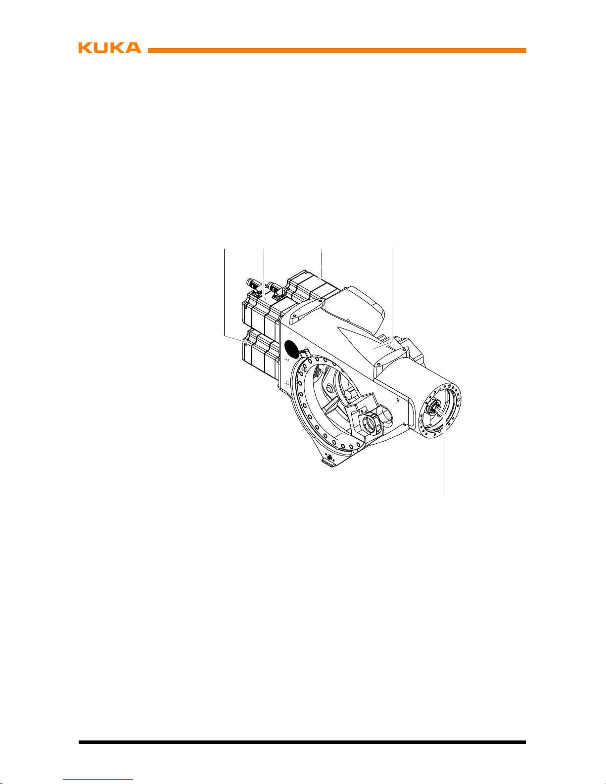
3.3.1 Wrist axis motor units A4 to A6
The wrist axes are driven by three motor units. These are fastened to the arm (Fig. 4/4) by
means of screws. Motor units A4 (3) and A5 (1) are of the same design and drive the respective wrist axes via toothed belts and shafts. Wrist axis A6 is driven directly by motor unit
A6 (2) via a push--on shaft (5).
Each motor unit for the wrist axis drives consists of a brushless AC servomotor with apermanent--magnet single--disk brake and a hollow--shaft resolver (both integrated).
1 Motor unit A5
2 Motor unit A6
3 Motor unit A4
4Arm
5 Shaft
4
5
1
A4
A6
A5
23
Fig. 4 Wrist axis motor units A4 to A6

3 Product description (continued)
15 of 122
MA KR 30, 60 HA, KR C4 04.11.02 en
3.4 Link arm
The link arm (Fig. 5/1) is the driven element of axis 2. It pivots about rotational axis 2 (3)
through an effective software range from +35° to --135°⎯referred to the zero position of
axis 2, which corresponds to the horizontal position of the link arm in Fig. 5. The effective
software swivel range is limited by mechanical limit stops with a buffer function in addition
to the software limit switches.
1Linkarm
2 Main axis motor unit A2
3 Rotational axis 2
1
3
+35°
2
--135˚
Fig. 5 Link arm with turning range
The link arm (Fig. 6/6) houses gear unit A3 (2) at its upper end, and gear unit A2 (3) at its
lower end. The gear units (2, 3) are used both as drive elements and to support the arm and
link arm assemblies. The reference notch (1) and the gauge cartridge (4) are provided to define and locate the mechanical zero position of axes 2 and 3. The cables for energy supply
and signal transmission are routed in the interior of the link arm housing from the rotating
column to the arm.

Assembly Instructions
16 of 122
MA KR 30, 60 HA, KR C4 04.11.02 en
1 Reference notch A3 5 Rotational axis 2
2 Gear unit A3 6 Link arm
3 Gear unit A2 7 Rotational axis 3
4 Gauge cartridge A2
1
2
3
4
5
6
7
Fig. 6 Structure of link arm

3 Product description (continued)
17 of 122
MA KR 30, 60 HA, KR C4 04.11.02 en
3.4.1 Main axis motor units A1 to A3
The robot axes 1, 2 and 3 are driven by motor units as shown in Fig. 7. Each motor unit for
the main axis drives consists of a brushless AC servomotor (1) with a permanent--magnet
single--disk brake and hollow--shaft resolver (2), both integrated. The motor units for
axes 1, 2 and 3 are of the same design.
Axis 2 of the KR 60 is equipped with a more powerful motor unit.
1
2
2
1ACservomotor
2 Hollow--shaft resolver
Fig. 7 Motor unit for main axis drive

Assembly Instructions
18 of 122
MA KR 30, 60 HA, KR C4 04.11.02 en
3.5 Rotating column
The rotating column (Fig. 8/2) is the assembly located between the link arm and the base
frame. Screwed to the base frame (4) through a special reduction gear unit (3), which allows
it to rotate, it performs movements about rotational axis 1 (1). It has an effective software
turning range of 185° in both the (+) and (--) directions, measured from the zero position of
axis (6). This range is limited by mechanical limit stops with a buffer function in addition to
the software limit switches. This limit stop system operates with a trailing stop acting on both
sides, which is installed in the base frame and mechanically limits the large turning range of
185˚ in both directions.
1 Rotational axis 1
2 Rotating column
3 Special reduction gear unit
4Baseframe
5 Main axis motor unit A2
6 Zero position A1
6
5
--185°
+185°
2
3
4
1
Fig. 8 Rotating column with turning range (shown here: KR 30 HA)

3 Product description (continued)
19 of 122
MA KR 30, 60 HA, KR C4 04.11.02 en
The main axis motor unit for axis 1 (Fig. 9/3) is installed in the rotating column with a special
reduction gear unit (4), and the main axis motor unit for axis 2 (1) is mounted on the side of
the rotating column with its special reduction gear unit (2).
Part of the manipulator electrical installations is routed inside the rotating column.
1 Main axis motor unit A2
2 Special reduction gear unit A2
3 Main axis motor unit A1
4 Special reduction gear unit A1
1
4
2
3
Fig. 9 Structure of rotating column
3.6 Base frame
The base frame (Fig. 10) is the stationary part of the manipulator, on which the rotating column turns with the link arm, the arm and the wrist. Its base flange (5) features through-holes (4) for holding the manipulator down and twolocating boreholes (6), with which the manipulator can be placed on two locating pins (accessories, see Chapter 7, “Installation”).
Attached to a flange inside the base frame housing (3) is the special reduction gear unit (1)
of axis 1. Also integrated into this flange is the double--acting trailing stop, which together with
a stop block on the rotating column mechanically safeguards the software--limited movement
range of 370° about rotational axis 1.
In the base frame, the installation cables leading to the rotating column are routed stress-free about rotational axis 1 of the manipulator in a flexible tube. The space between the rotating column and the base frame is provided with two detachable, one--piece covers (2, 8).
The sockets for the connecting cables from the manipulator to the control cabinet are located
on the RDC box (10) and MFH (7).
The reference notch (11) necessary for determining the mechanical zero position is found
on the bracket (9).

Assembly Instructions
20 of 122
MA KR 30, 60 HA, KR C4 04.11.02 en
1 Special reduction gear unit A1 7 Junction box
2 Cover 8 Cover
3 Base frame housing 9 Bracket
4 Attachment holes (6x) 10 MFH, multi-- function housing
5 Base flange 11 Reference notch
6 Locating boreholes (2x)
1
2
3
4
6
7
5
88
9
11
10
Fig. 10 Structure of base frame
3.7 Working range limitation for A1 to A3
Mechanical stops for task--related limitation of the respective working range for axes 1 to 3
can be supplied as the “Working range limitation” accessory (see documentation “Working
Range Limitation”).
Axis 1: with two supplementary stops:
from +58° to +185° and --58° to --185°, adjustable in steps of 15°.
Axis 2: from +5° to +65° and --5° to --20°, adjustable in steps of 15°.
Axis 3: from +3° and --108° to --153° or --33° to --153°, adjustable in steps of 15°.

3 Product description (continued)
21 of 122
MA KR 30, 60 HA, KR C4 04.11.02 en
3.8 Working range monitoring for A1 and A2
Axes 1 and 2 can be equipped with position switches and slotted rings to which adjustable
cams are attached (see documentation “Working Range Monitoring”). This allows the position of the manipulator to be continuously monitored.
Up to three sectors of the movement range can be monitored on axis 1, and a maximum of
one sector on axis 2.
3.9 Energy supply system
For use in certain production technologies, the industrial robot can be equipped with an energy supply system installed between the base frame and axis 6. The energy supply system
consists of a dress package (cable and hose bundle) for transmitting the energy and fluids
typical for the specific application, and the “Group of holders for energy supply system” required for attaching it to the manipulator. The energy supply system accommodates the
cables and hoses and ensures that they are guided with minimum stress throughout the permitted working envelope. The design of the energy supply system is suitable for the majority
of applications in terms of reach and resistance to wear. There may, of course, be applications for which this version is of only limited use. A special version is required in such cases,
or a corresponding adaptation of the energy supply system.
The energy supply system is described in separate documentation.

Assembly Instructions
22 of 122
MA KR 30, 60 HA, KR C4 04.11.02 en

4 Technical data
23 of 122
MA KR 30, 60 HA, KR C4 04.11.02 en
4 Technical data
Information!
This description applies analogously to all of the industrial robots listed in Chapter 1,
regardless of the variant or model shown in the illustrations.
4.1 General
The industrial robots are six--axis manipulators for installation on the floor or on the ceiling.
They are suitable for all continuous--path controlled tasks. The main areas of applicationare:
-- Machining
-- Handling
-- Assembly
-- MIG/MAG welding
-- YAG laser beam welding
Notice!
Using the manipulator for purposes other than those mentioned above is consi-
dered contrary to its designated use (see Chapter 2, “Purpose”).
Fig. 11 shows the industrial robot with the manipulator (= robot arm and electrical installa-
tions) and the control cabinet.
The following data apply, unless otherwise indicated, to both floor--mounted and ceiling-mounted robots.

Assembly Instructions
24 of 122
MA KR 30, 60 HA, KR C4 04.11.02 en
1 Arm 5 Base frame
2 In--line wrist 6 Connecting cables
3 Link arm 7 Control cabinet (see
4 Rotating column separate documentation)
12
3
4
5
6
3
7
Fig. 11 Principal robot components

4 Technical data (continued)
25 of 122
MA KR 30, 60 HA, KR C4 04.11.02 en
4.2 Principal data
Type KR 30 HA
KR 60 HA
KR 60 L45 HA
KR 60 L30 HA
Number of axes 6 (Fig. 13)
Load limits see following table and Fig. 12
Robot type
KR 30 HA KR 60 HA
KR 60 L45
HA
KR 60 L30
HA
Wrist (IW)
1
IW 30/45/60 IW 30/45/60 IW 30/45/60 IW 30/45/60
Rated payload [kg] 30 60 45 30
Max. supplementary
load with rated payload
[kg]
35 35 35 35
Max. total load [kg] 65 95 80 65
1
IW = In--line wrist III
Payload
Max. total load
P
Suppl. load
Fig. 12 Load distribution
Axis data See the following table.
All specifications in the “Range of motion” column are referred to the electrical zero of the robot axis concerned.

Assembly Instructions
26 of 122
MA KR 30, 60 HA, KR C4 04.11.02 en
KR 30 HA
D In--line wrist, rated payload 30 kg
Axis
Range of motion,
software--limited
Speed
1 ±185˚ 140˚/s
2 +35˚
to
--135˚
126˚/s
3 +158˚
to
--120˚
140˚/s
4 ±350˚ 260˚/s
5 ±119˚ 245˚/s
6 ±350˚ 322˚/s
KR 60 HA
D In--line wrist, rated payload 60 kg
Axis
Range of motion,
software--limited
Speed
1 ±185˚ 128˚/s
2 +35˚
to
--135˚
102˚/s
3 +158˚
to
--120˚
128˚/s
4 ±350˚ 260˚/s
5 ±119˚ 245˚/s
6 ±350˚ 322˚/s
KR 60 L45 HA
D In--line wrist, rated payload 45 kg
Axis
Range of motion,
software--limited
Speed
1 ±185˚ 128˚/s
2 +35˚
to
--135˚
102˚/s
3 +158˚
to
--120˚
128˚/s
4 ±350˚ 260˚/s
5 ±119˚ 245˚/s
6 ±350˚ 322˚/s

4 Technical data (continued)
27 of 122
MA KR 30, 60 HA, KR C4 04.11.02 en
KR 60 L30 HA
D In--line wrist, rated payload 30 kg
Axis
Range of motion,
software--limited
Speed
1 ±185˚ 128˚/s
2 +35˚
to
--135˚
102˚/s
3 +158˚
to
--120˚
128˚/s
4 ±350˚ 260˚/s
5 ±119˚ 245˚/s
6 ±350˚ 322˚/s
A1
Fig. 13 Rotational axes and their directions of rotation

Assembly Instructions
28 of 122
MA KR 30, 60 HA, KR C4 04.11.02 en
Pose repeatability KR 30 HA ± 0.05 mm
(ISO 9283) KR 60 HA ± 0.05 mm
KR 60 L45 HA ± 0.05 mm
KR 60 L30 HA ± 0.05 mm
Mounting position floor, ceiling
Floor--mounted and ceiling--mounted manipulators must be
calibrated for the respective installation position.
Principal dimensions see Fig. 18 and Fig. 19.
Working envelope The shape and dimensions of the working envelope maybe
noted from Fig. 18 and Fig. 19.
Volume of working envelope KR 30 HA approx. 27.24 m
3
KR 60 HA approx. 27.24 m
3
KR 60 L45 HA approx. 36.89 m
3
KR 60 L30 HA approx. 47.78 m
3
The reference point is the intersection of axes 4 and 5.
Load center of gravity P seeFig.14toFig.16.
For the rated payload, the horizontal distance of the load
center of gravity P from the face of the mounting flange is
150 mm; the vertical distance from rotational axis 6 is
120 mm (nominal distance in each case).
Weight KR 30 HA approx. 665 kg
KR 60 HA approx. 665 kg
KR 60 L45 HA approx. 671 kg
KR 60 L30 HA approx. 679 kg
Principal dynamic loads See Fig. 21
Drive system Electromechanical, with transistor--controlled ACservomo-
tors.
Installed motor capacity approx. 14.9 kW
Protection classification of the robot
IP 64
ready for operation, with connecting cables plugged in
(according to EN 60529).
Protection classification of the in--line wrist
(standard) IP 65 (according to EN 60529)

4 Technical data (continued)
29 of 122
MA KR 30, 60 HA, KR C4 04.11.02 en
Ambient temperature during operation:
283 K to 328 K (+10 °Cto+55°C),
during storage/transportation:
233 K to 333 K (--40 °Cto+60°C).
Other temperature limits available on request.
Humidity class DIN EN 60721--3--3, Class 3K3
Sound level < 75 dB (A) outside the working envelope
(Fig. 18 and Fig. 19)
Color Manipulator
Manipulator overall: KUKA --Orange 2567
Motors: Black (RAL 9005)
Cover A1 Black (RAL 9005)
Plates seeFig.22toFig.30.
Special consumables none
Stopping distances and times
see separate documentation

Assembly Instructions
30 of 122
MA KR 30, 60 HA, KR C4 04.11.02 en
Notice!
Concerning Fig. 14 to Fig. 16:
These loading curves and the values in the table correspond to the maximum
load capacity. Both values (payload and principal moment of inertia) must be
checked in all cases. Exceeding this capacity will reduce the service life of the
robot and generally overload the motors and the gears; in any such case KUKA
must be consulted beforehand.
Information!
The values determined here are necessary for planning the application.
For commissioning the robot, additional input data are required in accordance with the
KUKA software documentation.
-- X
Lz
Lx
Ly
+X
-- Y
+Y
+Z
-- Z
Load center of gravity
Lxy
Lxy = Lx2+ Ly
2
Robot flange coordinate system
Permissible mass inertia at the
design point
(Lxy = 180 mm,
Lz = 150 mm)
9kgm
2
.
CAUTION: The mass inertia must be
verified using KUKA Load. It is
imperative for the load data to be
entered in the controller!
Lxy (mm)
100 200 300 400 500 700600
100
200
300
400
Lz (mm)
500
A4
A5
A6
KR 30 HA
KR 60 L30 HA
30 kg
27 kg
24 kg
21 kg
18 kg
15 kg
13 kg
Fig. 14 Load center of gravity P and loading curves for KR 30 HA; KR 60 L30 HA
 Loading...