

Kuhnke PG 674 Instruction Manual

Kuhnke Electronics
Instruction Manual
E 390 GB
PG 674
Operating Terminal for KUAX 674 / 673
4 April 1996 / 65.135

This manual is primarily intended for the use of the designing engineer, the
project planning engineer, and the developing engineer. It does not give any
information about delivery possibilities. Data is only given to describe the
product and must not be regarded as guaranteed properties in the legal sense.
Any claims for damages against us – on whatever legal grounds – are excluded
except in instances of deliberate intent or gross negligence on our part.
We reserve the rights for errors, omissions or modifications.
Reproduction even of extracts only with the editor's express and written prior
consent.

Contents - 1
Table of contents
Table of contents
1. Introduction................................................................ 1-1
2. Reliability, Security...................................................... 2-1
2.1. Target group ............................................................................ 2-1
2.2. Reliability ................................................................................ 2-1
2.3. Notes...................................................................................... 2-2
2.3.1. Danger................................................................................. 2-2
2.3.2. Dangers caused by high contact voltage .................................. 2-2
2.3.3 Important information / cross reference..................................... 2-2
2.4. Security ................................................................................... 2-3
2.4.1. To be observed during project planning and installation............. 2-3
2.4.2. To be observed during maintenance and servicing .................... 2-4
2.4.3. Measures for the prevention of electrostatic charge.................... 2-4
3. Design of the PG 674..................................................3-1
3.1. Display and operating elements.................................................. 3-1
3.2. Hand-held terminal PG 674 (674.001.00) .................................. 3-2
3.3. Built-in terminal PG 674 (674.010.00) ....................................... 3-3
3.3.1. Design and Dimensions .......................................................... 3-3
3.3.2. Installation ............................................................................ 3- 4
3.3.2.1. Front panel cutout............................................................... 3- 4
3.3.2.2. Inserting the built-in terminal................................................. 3-4
3.4. Technical specifications ............................................................. 3-5

Contents - 2
Table of contents
4. The PG 674 as a programming device ..........................4-1
4.1. General information on the operating terminal ............................. 4-2
4.2. Front view................................................................................ 4-3
4.3. Key pad .................................................................................. 4- 4
4.3.1. Function keys ........................................................................ 4- 4
4.4. Operating modes of the operating terminal PG 674 ..................... 4-6
4.4.1. Restricted operating mode ...................................................... 4 -6
4.5. Display window of the operating terminal PG 674 ....................... 4-7
4.5.1. Standard display ................................................................... 4- 7
4.6. Commands of the operating terminal PG 674 .............................. 4-8
4.6.1. Activating the open mode (entering the key code)...................... 4-8
4.6.2. Exiting the open operating mode ............................................. 4-8
4.6.3. Displaying the key code ......................................................... 4- 9
4.6.4. Changing the key code .......................................................... 4- 9
4.6.5. System information .............................................................. 4-10
4.6.6. Displaying status and error messages..................................... 4-10
4.6.7. Choosing a program............................................................ 4-11
4.6.7.1. Giving access to the choice of program function .................. 4-11
4.6.7.2. Changing the program number ......................................... 4-13
4.6.8. Initializing the cam control unit.............................................. 4-14
4.6.9. Choosing an output ............................................................. 4-15
4.6.10 Programming cams ............................................................. 4-16
4.6.11. Optimizing cams ............................................................... 4-18
4.6.12. Displaying cams ................................................................ 4-19
4.6.13. Deleting cams ................................................................... 4-20
4.6.14. Deleting outputs................................................................. 4-21
4.6.15. Deleting programs ............................................................. 4-21
4.6.16. Copying programs............................................................. 4-22
4.6.17. Program transfer................................................................ 4-23
4.6.18. Activating the dynamic mode of outputs ............................... 4-24
4.6.19. Deadtime compensation ..................................................... 4-25
4.6.20. Time cams ........................................................................ 4-26
4.6.21. Encoder speed reduction – electronic gearing ....................... 4-27
4.6.22. Choice of language ........................................................... 4-28

Contents - 3
Table of contents
4.6.23. Setting the display contrast (as from version 2.0) ................... 4-29
4.6.24. Self-test of the operating terminal (as from version 2.0) .......... 4-30
4.6.25. Self-test of the operating terminal (versions < 2.0).................. 4-32
Index....................................................................... Index-1
Sales & Service

Contents - 4
Table of contents
1 - 1
Introduction
1. Introduction
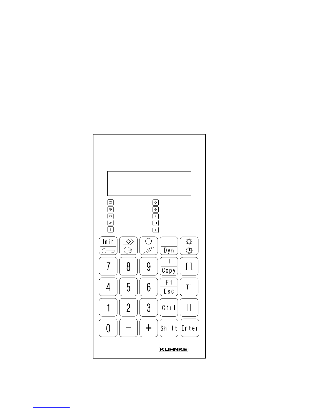
The PG 674 is a small, handy device with a keyboard and twoline display. It is used for operating the electronic cam control
units Posi Control KUAX 674 and KUAX 673. It is separated
from the cam control unit to allow variable use. It can be connected with the cam control unit via the programming interface
at any time, even when the machine is running. This makes it
easy to check or modify the programs at the machine.
Choic e of prog
Choic e of outpu t
Outputs off
Delete
Outputs on
Gear
Time cam
Show errors
Set cam
Choice of cam

1 - 2
Introduction
The PG 674 is available in two designs:
Hand-held terminal
As a portable hand-held terminal it can easily be transported
and connected to the control device. The integrated buffered
memory allows you to load programs from one controller and
transfer them to another controller.
Built-in terminal
As a built-in terminal the device is firmly built into i.e. the
door of the switching cabinet and is thus permanently available
as an operating and display device.
The present operating manual exclusively describes the hardware of the PG 674 and how you use it to operate controllers.
The control devices themselves are described elsewhere:
Controller Instruction manual
KUAX 674 E 375 GB
KUAX 673 E 293 GB
.

2 - 1
Reliability/Security
2. Reliability, Security
2.1. Target group
This instruction manual contains all information necessary for
the use of the described product (control device, software, etc.)
according to instructions. It is written for the
personnel of thepersonnel of the
personnel of thepersonnel of the
personnel of the
construction, project planning, service and commissioningconstruction, project planning, service and commissioning
construction, project planning, service and commissioningconstruction, project planning, service and commissioning
construction, project planning, service and commissioning
departmentsdepartments
departmentsdepartments
departments. For proper understanding and error-free applica-
tion of technical descriptions, instructions for use and particularly of notes of danger and warning,
extensive knowledge ofextensive knowledge of
extensive knowledge ofextensive knowledge of
extensive knowledge of
automation technologyautomation technology
automation technologyautomation technology
automation technology is compulsory.
2.2. Reliability
Reliability of Kuhnke controllers is brought to the highest possible standards by extensive and cost-effective means in their
design and manufacture.
Amongst which are:
· selecting high-quality components,
· quality arrangements with our sub-suppliers,
· measures for the prevention of static charge during the handling of MOS circuits,
· Worst-Case dimensioning of all circuits,
· inspections during various stages of fabrication,
· computer aided tests of all assembly groups and their
coefficiency in the circuit,
· stress-test in raised ambient temperatures during 72 hours
realtime with nominal load on the outputs,
· statistic assessment of the quality of fabrication and of all returned goods for immediate taking of adjustment measures.
Despite these measures, the occurrence of errors in electronic
control units - even if most highly improbable - must be taken
into consideration.
Text muß n
2 - 2
Reliability/Security
2.3. Notes
Please pay particular attention to the additional notes which we
have marked by symbols in this instruction manual:
2.3.1. Danger
This symbol warns you of dangers which may cause
death, (grievous) bodily harm or material damage if the
described precautions are not taken.
2.3.2. Dangers caused by high contact voltage
This symbol warns you of dangers of death or (grievous)
bodily harm which may be caused by high contact
voltage if the described precautions are not taken.
2.3.3 Important information / cross reference
This symbol draws your attention to important additional
information concerning the use of the described product.
It may also indicate a cross reference to information to be
found elsewhere.

2 - 3
Reliability/Security
2.4. Security
Our product normally becomes part of larger systems or installations. The following notes are intended to help integrating the
product into its environment without dangers for man or material/equipment.
2.4.1. To be observed during project planning and installation
- 24V DC power supply:
· provide sufficient separation of low voltage,
· apply power packs in accordance with IEC 364-4-41 or
CENELEC HD 384.4.41 (VDE 0100, Part 410) respectively.
- In case of power breakdowns or power fades: the program has
to be structured in such a way as to create a defined state at
restart that excludes dangerous states.
- Emergency switches or other emergency installations have to
be realized in accordance with EN 60204/IEC 204
(VDE 0113). They have to be effective at any time.
- Safety and precautions regulations for qualified applications
have to be observed.
- Please pay particular attention to the notes of warning (→
2.3. Notes) which, at relevant places, will make you aware of
possible sources of errors.
- The relevent standards and VDE regulations are to be observed in every case.
- Control elements have to be installed in such a way as to exclude unintended operation.
- Control cables have to be layed in such a way as to exclude
interference (inductive or capacitive) which could influence
the operation of the controller.
To achieve a high degree of conceptual safety in planning
and installing an electronic controller it is essential to
follow the instructions given in the manual exactly because wrong handling could lead to rendering measures
against dangerous failures ineffective or to creating
additional dangers.

2 - 4
Reliability/Security
2.4.2. To be observed during maintenance and servicing
- During measuring and checking operations on a controller in
a power-up condition, precaution regulation VBG 4.0 has to
be observed and §8 (Admissible deviations during working on
parts) in particular.
- Repairs must only be executed by the trained Kuhnke personnel (usually in the main factory in Malente). Warranty expires in any other case.
- Spare parts:
Only use parts approved of by Kuhnke. Only genuine Kuhnke
modules must be used in modular controllers.
- Modules must only be connected to or disconnected from the
controller with no voltage supplied. Otherwise they may be
destroyed or (possibly not immediately recognizably!) detracted from their proper functioning.
- Always deposit batteries and accumulators as special waste.
2.4.3. Measures for the prevention of electrostatic charge
Electrostatic charge is dangerous for components and assembly
groups. It is a peculiarity of electrostatics to not destroy the sensitive components but to damage them in a not immediately
conceivable way. It is because of this that devices stop functioning after some time of service.
The ESD measures (ESD = electrostatic discharge) executed in
the factory are only guaranteed to be effective if they are also
regarded by the user (service).
Please note:
- Only store parts in their factory-packing or in an antistatic
packing of similar quality.
- Assembly groups must only be touched by persons who are
grounded via a wrist bracelet and/or a discharging mat and
shoe-grounding strips ( observe protection of people!).
- Only ship assembly groups in their factory-packing or in an
antistatic packing of similar quality.
Reference to literature (Fa. 3M Deutschland GmbH,
Neuss): Information brochure
Interesting Facts about Electrostatics in Micro-Electronics
3 - 1
Hardware
Choic e of pr o g
Choic e of ou t pu t
Outputs off
Delete
Outputs on
Gear
Time cam
Show errors
Set cam
Choice of cam
3. Design of the PG 674
The operating terminal PG 674 is used for programming the
cam control unit (see "4. The PG 674 as a programming device").
It can be supplied as a portable hand-held terminal and as a
built-in terminal.
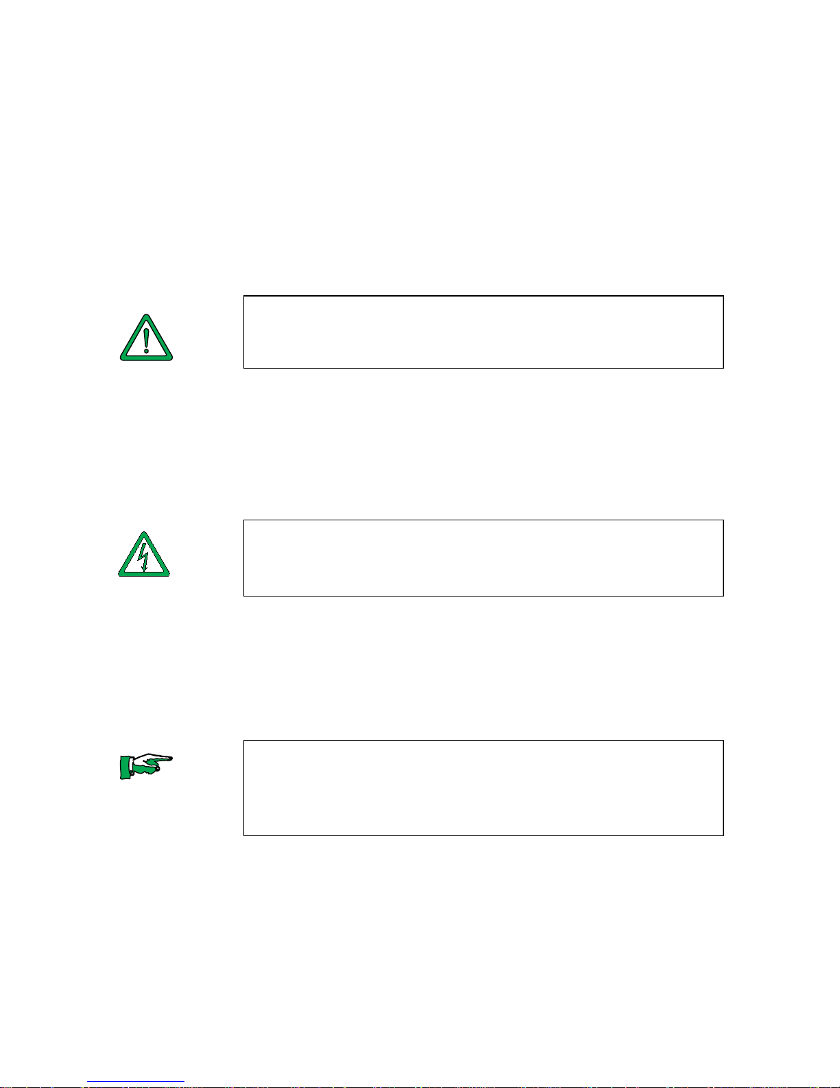
3.1. Display and operating elements
LCD display (see ch. 4)
Short description of the function keys
Keyboard
(for function see ch. 4)
3 - 2
Operating terminal PG 674
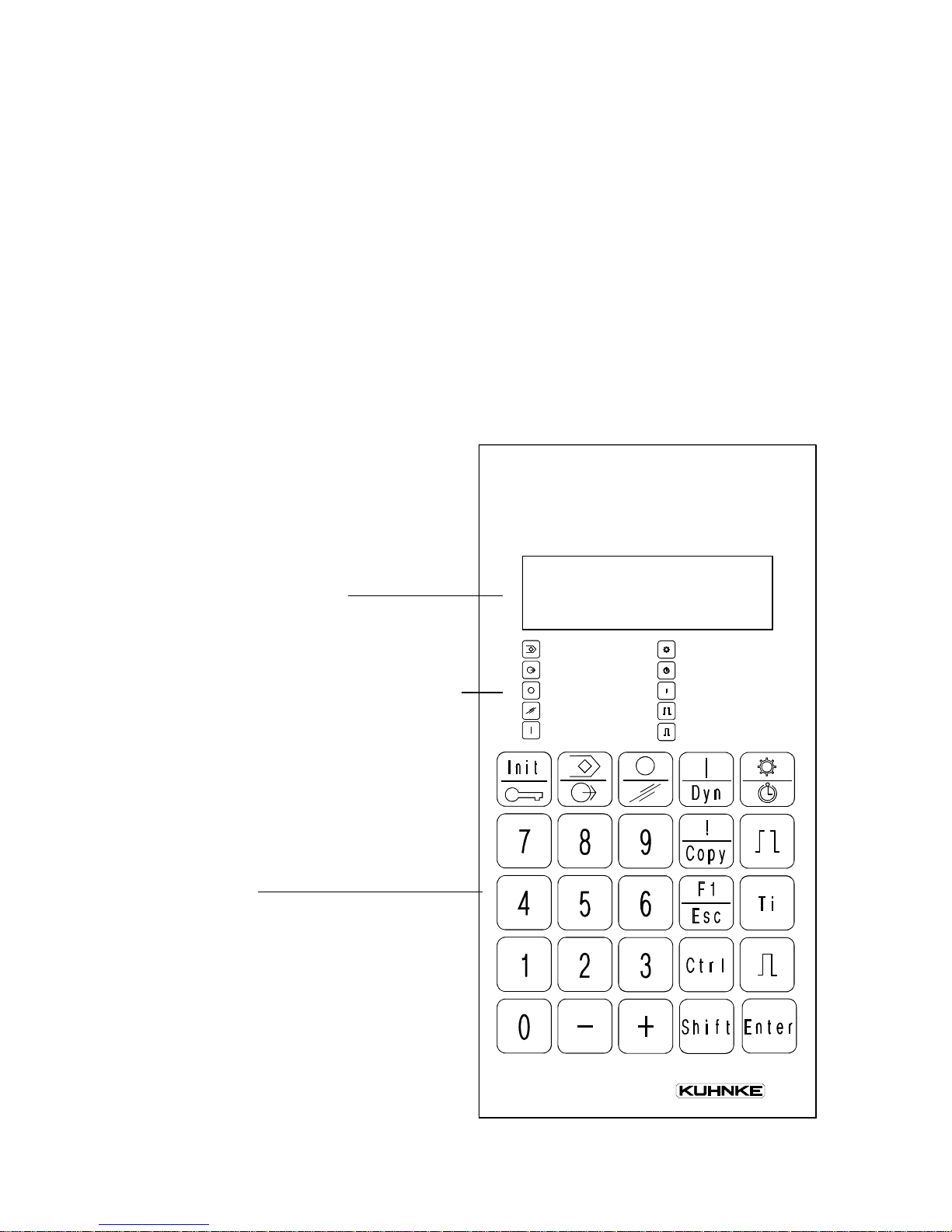
3.2. Hand-held terminal PG 674 (674.001.00)
The hand-held terminal can be connected to and disconnected
from the cam control unit during operation.
The connecting cable is firmly attached to the hand-held terminal. It serves both communication with the cam control unit and
supplying power to the hand-held terminal (24 V DC), which
are supplied by the cam control unit.
Gear
Time c am
Show errors
Set cam
Choice of cam
Choice of prog
Choice of output
Outputs off
Delete
Outputs on
3 - 3
Hardware
3.3. Built-in terminal PG 674 (674.010.00)
As a built-in terminal, the PG 674 has a connector on the rear
side for the connecting cable to the cam control unit. The 24 V
DC supply voltage is separately connected to a 2-pin screw-type
locking connector.
The built-in terminal is expected to be available as from
Version 2.0 in the spring of 1995.
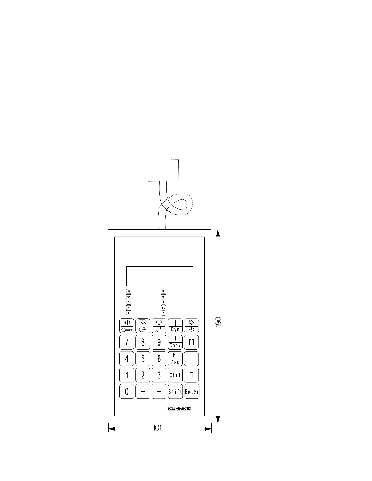
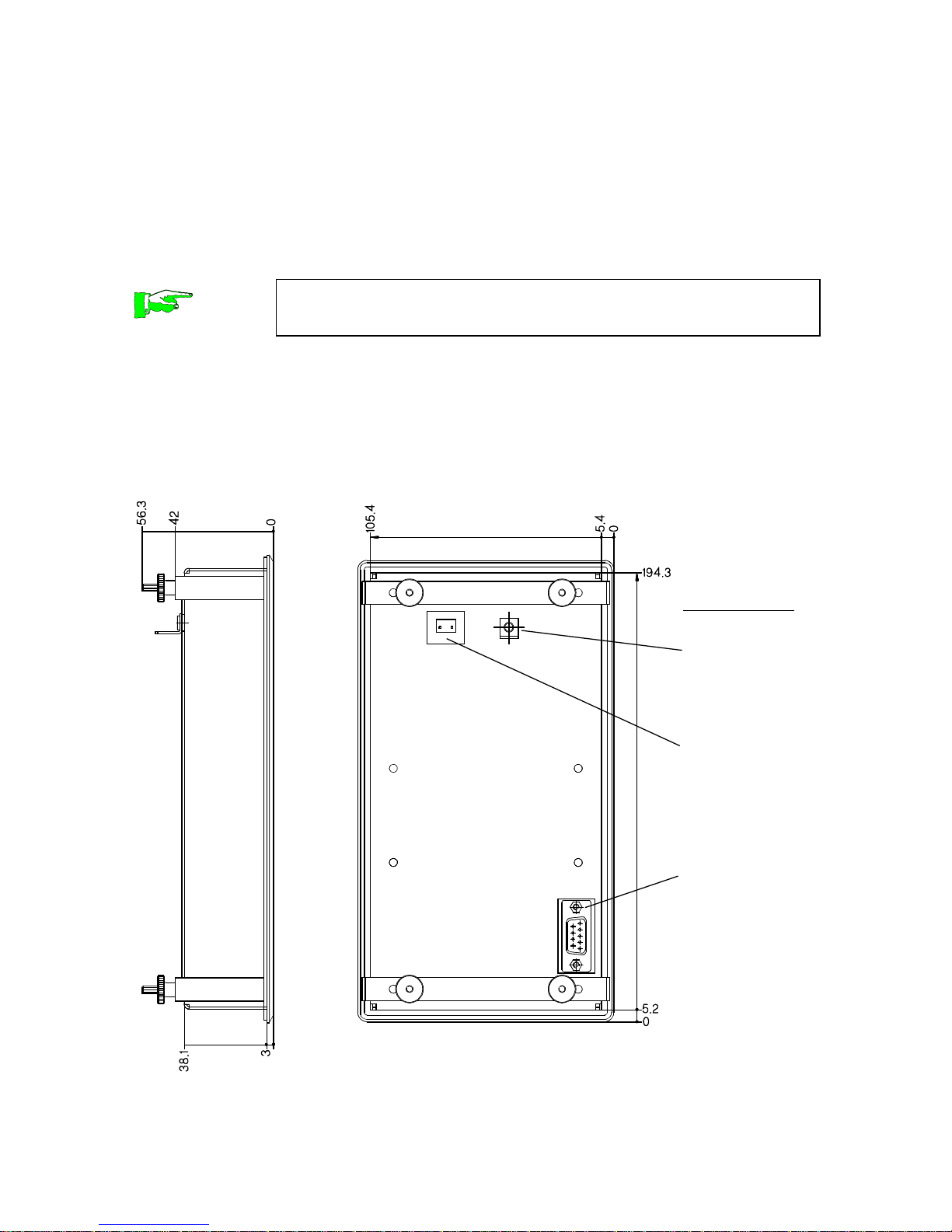
3.3.1. Design and Dimensions
Side view Rear view
Connections:
Faston connector for protective ground
Screw-type
locking connector for 24 V DC
supply
Sub-D connector for connecting cable to the
cam control
unit
Cable order no.: 674.150.31
+24V 0 V
3 - 4
Operating terminal PG 674
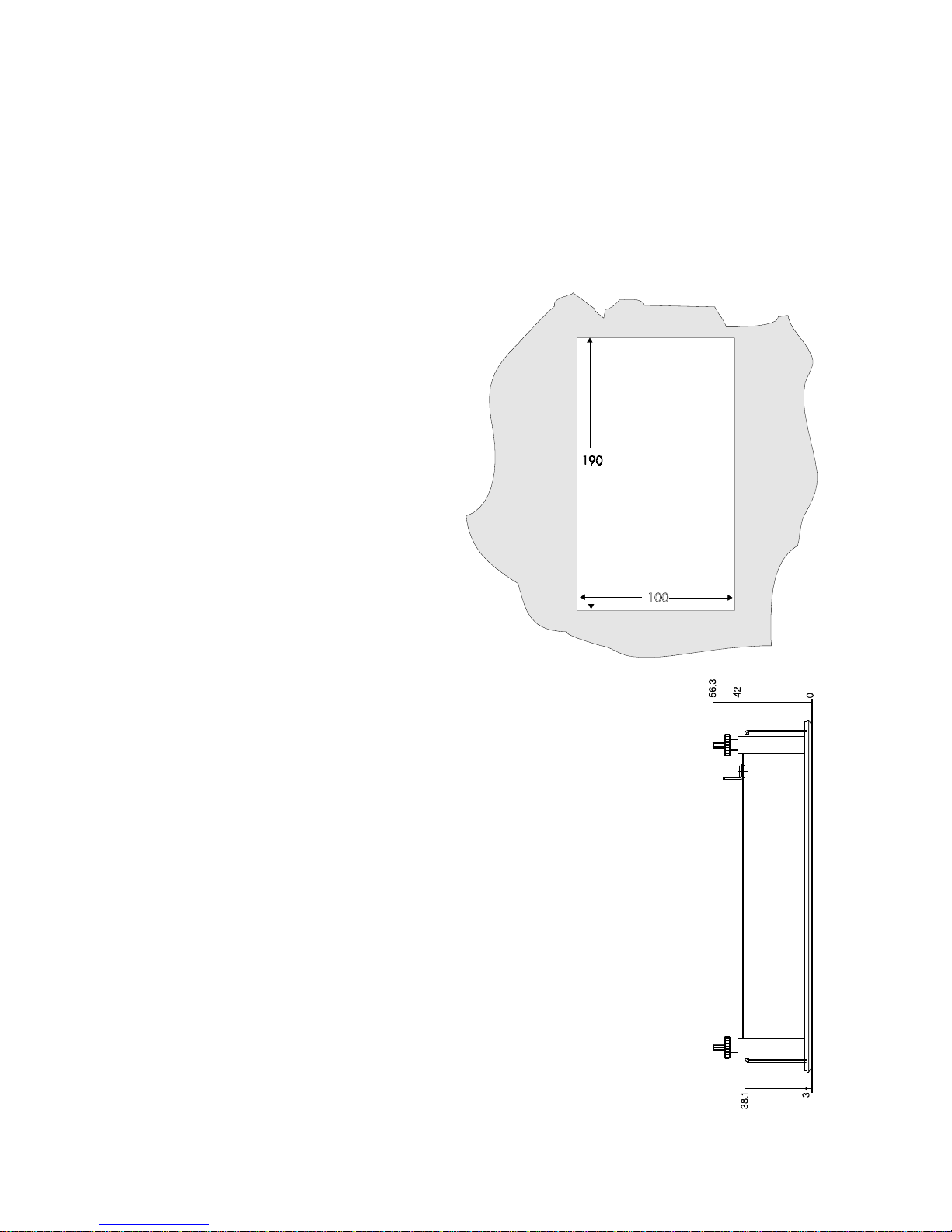
3.3.2. Installation
The PG 674 is installed in a front panel (i.e. switching cabinet
door).
To do this you must cut out an opening in the front panel:
3.3.2.1. Front panel cutout
3.3.2.2. Inserting the built-in terminal
- Remove the rear mounting brackets of the PG
674:
to do this unscrew the 4 nuts.
- Push the PG 674 from the front into the front
panel cutout.
- Screw the mounting brackets on again.
 Loading...