

Page 1

Kuhnke Electronics
Instruction Manual
Modules of Controllers
KUAX 680I, KUAX 680C, KDT 680CT
E 326 GB
7 May 1997 / 39.785
Page 2

This manual is primarily intended for use by design, project, and development
engineers. It does not give any information about delivery possibilities. Data
is only given to describe the product and must not be regarded as guaranteed
properties in the legal sense. Any claims for damages against us - on whatever
legal grounds - are excluded except in instances of deliberate intent or gross
negligence on our part.
We reserve the rights for errors, omissions and modifications.
Reproduction even of extracts only with the editor's express and written prior
consent.
Page 3

Table of contents
Table of contents
1. Introduction............................................................... 1-1
1.1. Manual breakdown ................................................................. 1-2
1.2. Further modules....................................................................... 1-3
2. Safety and Reliability.................................................. 2-1
2.1. Target group ........................................................................... 2-1
2.2. Reliability ............................................................................... 2-1
2.3. Notes..................................................................................... 2- 2
2.3.1. Danger................................................................................ 2- 2
2.3.2. Dangers caused by high contact voltage ................................. 2-2
2.3.3 Important information / cross reference.................................... 2-2
2.4. Safety .................................................................................... 2- 3
2.4.1. To be observed during project planning and installation............ 2- 3
2.4.2. To be observed during maintenance and servicing ................... 2-4
2.5. Electromagnetic compatibility .................................................... 2-5
2.5.1. Definition............................................................................. 2-5
2.5.2. Resistance to interference ...................................................... 2-5
2.5.3. Interference emission ............................................................. 2-6
2.5.4. General notes on installation.................................................. 2-6
2.5.5. Protection against external electrical influences ........................ 2-7
2.5.6. Cable routing and wiring....................................................... 2-7
2.5.7. Location of installation ........................................................... 2-8
2.5.8. Particular sources of interference ............................................ 2-8
3. Modules and slots ...................................................... 3-1
3.1. Design.................................................................................... 3-2
3.2. Screw-type locking connectors................................................... 3-3
3.2.1. Coding................................................................................ 3-3
3.3. Slots....................................................................................... 3-4
3.3.1. Function slots ....................................................................... 3-4
3.4. Service modules ...................................................................... 3-5
3.4.1. Transfer address ranges ........................................................ 3-5
3.4.2. Interrupt modules .................................................................. 3-5
3.5. Power supply of inputs and outputs............................................ 3-6
3.6. Differences between KUAX 680C/KDT 680CT and KUAX 680I.... 3- 7
Contents - 1
Page 4

Table of contents
4. Digital inputs and outputs............................................ 4-1
4.1. Plugging digital input and output modules .................................. 4- 2
4.1.1. Addressing (input/output groups and channels)........................ 4-2
4.1.2. Reserved slots ...................................................................... 4-3
4.2. Digital input modules ............................................................... 4 -4
4.2.1. Input module, 24 V DC, 8 inputs ............................................ 4-5
4.2.1.1. Technical specifications ...................................................... 4-6
4.2.2. Input module, 24 V DC, 8 inputs, with real-time clock ............... 4-7
4.2.2.1. Real-time clock .................................................................. 4-7
4.2.2.2. Parameters of KUBES module “CLOCK” ............................... 4-8
4.2.2.3. Programming suggestion for the real-time clock ................... 4-10
4.2.2.4. Technical specifications .................................................... 4-11
4.2.3. Input module, 24 V DC, 16 inputs ........................................ 4-12
4.2.3.1. Technical specifications .................................................... 4-13
4.2.4. Input module, 24 V DC, 8 inputs, 1 ms ................................. 4-14
4.2.4.1. Technical specifications .................................................... 4-15
4.2.5. Input module, 24 V DC, 16 inputs, 1 ms ............................... 4-16
4.2.5.1. Technical specifications .................................................... 4-17
4.2.6. Input module, 24 V DC, 16 inputs, interrupt capability............ 4-18
4.2.6.1. Signal delay ................................................................... 4-18
4.2.6.2. Interrupt inputs ................................................................ 4-20
4.2.6.3. Technical specifications .................................................... 4-23
4.3. Digital output module, 24 V DC, 0.5 A, 8 outputs ..................... 4-24
4.3.1 Technical specifications ........................................................ 4-26
4.4. Digital input/output module, 24 V DC, 8/8.............................. 4-27
4.4.1. Technical specifications ....................................................... 4-28
4.5. Pneumatic output module, 4 outputs 3/2 way ........................... 4-29
4.5.1. Technical specifications ....................................................... 4-30
5. Analogue inputs and outputs ....................................... 5-1
5.1. Plugging analogue input and output modules .............................. 5-2
5.1.1. Addressing (anal. input/output groups and channels) ............... 5 -2
5.1.2. Reserved slots ...................................................................... 5-3
5.2. Analogue input modules........................................................... 5-5
5.2.1. Analogue input module, 0...10 V, 10 bit, 4 channels ............... 5-5
5.2.1.1. Slots................................................................................. 5-5
5.2.1.2. Connectors ....................................................................... 5-6
5.2.1.3. Representation of the analogue value................................... 5-6
5.2.1.4. Technical specifications ...................................................... 5-7
5.2.2. Analogue input module, 0(4)...20 mA, 10bit, 4 channels.......... 5-8
Contents - 2
Page 5

Table of contents
5.2.2.1. Slots ................................................................................. 5-8
5.2.2.2. Connections ...................................................................... 5-9
5.2.2.3. Representation of the analogue value................................... 5-9
5.2.2.4. Transfer address ranges ................................................... 5-10
5.2.2.5. Technical specifications.................................................... 5-11
5.2.3. Analogue input module, PT100, 0...300 °C, 10 bit,............... 5-12
5.2.3.1. Slots ............................................................................... 5-12
5.2.3.2. Connectors ..................................................................... 5-13
5.2.3.3. Transfer address ranges ................................................... 5-14
5.2.3.4. Evaluation in the user program .......................................... 5-15
5.2.3.5. Technical specifications.................................................... 5-16
5.2.4. Analogue input module, thermocouple NiCrNi (type K),.......... 5-17
5.2.4.1. Slots ............................................................................... 5-17
5.2.4.2. Connections .................................................................... 5-18
5.2.4.3. Transfer address ranges ................................................... 5-19
5.2.4.4. Evaluation in the user program .......................................... 5-20
5.2.4.5. Technical specifications.................................................... 5-21
5.2.5. Analogue input module, potentiometer, 10bit, 4 channels ....... 5-22
5.2.5.1. Slots ............................................................................... 5-22
5.2.5.2. Connectors ..................................................................... 5-23
5.2.5.3. Representation of the analogue value................................. 5-24
5.2.5.4. Technical specifications.................................................... 5-25
5.3. Analogue output modules ....................................................... 5-27
5.3.1. Analogue output module, 0...10 V, 8 bit, 4 channels ............. 5-27
5.3.1.1. Slots ............................................................................... 5-27
5.3.1.2. Connectors ..................................................................... 5-28
5.3.1.3. Repesentation of the analogue value.................................. 5-28
5.3.1.4. Technical specifications.................................................... 5-29
5.3.2. Analogue output module, 0(4)...20 mA, 8bit, 4 channels........ 5-31
5.3.2.1. Slots ............................................................................... 5-31
5.3.2.2. Connectors ..................................................................... 5-32
5.3.2.3. Repesentation of the analogue value.................................. 5-32
5.3.2.4. Transfer address ranges ................................................... 5-33
5.3.2.5. Technical specifications.................................................... 5-34
5.4. Analogue input/output modules .............................................. 5-35
5.4.1. Analogue I/O module, 2 I 0...10 V, 2 O 0...±10V ................ 5-35
5.4.1.1. Slots ............................................................................... 5-36
5.4.1.2. Connectors ..................................................................... 5-37
5.4.1.3. Representation of the analogue value................................. 5-38
5.4.1.4. Technical specifications.................................................... 5-39
Contents - 3
Page 6

Table of contents
5.4.2. Analogue I/O module, 2 I 0...20 mA, 2 O 0...±10V ............. 5-40
5.4.2.1. Slots............................................................................... 5-40
5.4.2.2. Connectors ..................................................................... 5-41
5.4.2.3. Representation of the analogue value................................. 5-42
5.4.2.4. Transfer address ranges of the analogue inputs................... 5-43
5.4.2.5. Technical specifications .................................................... 5-44
5.4.3. Analogue I/O module, 2 I 0...10 V, 2 O 0...20 mA .............. 5-45
5.4.3.1. Slots............................................................................... 5-46
5.4.3.2. Connectors ..................................................................... 5-47
5.4.3.3. Representation of the analogue value................................. 5-48
5.4.3.4. Transfer address ranges of the analogue inputs................... 5-49
5.4.3.5. Technical specifications .................................................... 5-50
5.4.4. Anal. I/O module, 2 I 0...20 mA, 2 O 0...20 mA................. 5-51
5.4.4.1. Slots............................................................................... 5-51
5.4.4.2. Connectors ..................................................................... 5-52
5.4.4.3. Representation of the analogue value................................. 5-53
5.4.4.4. Transfer address ranges ................................................... 5-54
5.4.4.5. Technical specifications .................................................... 5-55
6. Counter modules........................................................ 6-1
6.1. Counter module, 1 or 2 multi-function counters, 24bit .................. 6-2
6.1.1. Functions ............................................................................. 6-2
6.1.2. Slots.................................................................................... 6-2
6.1.3. Counter modules with 24V inputs ........................................... 6-3
6.1.3.1. Connectors ....................................................................... 6-3
6.1.3.2. Technical specifications ...................................................... 6-5
6.1.4. Counter module with RS422 interface ..................................... 6 -6
6.1.4.1. Connectors ....................................................................... 6-6
6.1.4.2. Technical specifications ...................................................... 6-7
6.1.5. Programming ....................................................................... 6-8
6.1.5.1. Transfer address ranges and interrupt modules...................... 6- 8
6.1.5.2. Control flags ................................................................... 6-10
6.1.5.3. Setting the counter to the preset value / to 0....................... 6-10
6.1.5.4. Setting the reference value................................................ 6-10
6.1.5.5. Counter control ............................................................... 6-11
6.1.5.6. Reference value............................................................... 6-11
6.1.5.7. Interrupt.......................................................................... 6-12
6.2. Counter module, 2 event counters, 16bit .................................. 6-13
6.2.1. Slots.................................................................................. 6-13
6.2.2. Connectors ........................................................................ 6-14
Contents - 4
Page 7

Table of contents
6.2.3. Technical specifications....................................................... 6-15
6.2.4. Programming ..................................................................... 6-16
6.2.4.1. Transfer address ranges ................................................... 6-16
6.2.4.2. Setting the counter to the preset value / to 0....................... 6-18
6.2.4.3. Switching the counter on / off........................................... 6-18
6.2.4.4. Selecting the counting direction ......................................... 6-18
6.2.4.5. Selecting the counting mode ............................................. 6-18
6.2.4.6. Clearing the count ........................................................... 6-18
6.2.4.7. Evaluating the count......................................................... 6-18
6.3. SSI module, 24 bit, for 2 absolute value devices ....................... 6-19
6.3.1. Slots.................................................................................. 6-19
6.3.2. Connectors ........................................................................ 6-20
6.3.3. Technical specifications....................................................... 6-21
6.3.4. Programming ..................................................................... 6-22
6.3.4.1. Transfer address ranges ................................................... 6-22
6.3.4.2. User program.................................................................. 6-24
7. Communication modules............................................. 7-1
7.1. V.24 (RS 232) module ............................................................. 7-1
7.1.1. Slots.................................................................................... 7-1
7.1.2. Connector ............................................................................ 7 -2
7.1.3. Technical specifications......................................................... 7-3
7.2. TTY module (20 mA) ................................................................ 7-4
7.2.1. Slots.................................................................................... 7-4
7.2.2. Connector ............................................................................ 7 -5
7.2.3. Technical specifications......................................................... 7-6
7.3. RS 485 module ....................................................................... 7-7
7.3.1. Slots.................................................................................... 7-7
7.3.2. Connector ............................................................................ 7 -8
7.3.3. Technical specifications......................................................... 7-9
7.4. Programming the V.24, TTY and RS 485 modules ..................... 7-10
7.4.1. Communication programs SE 680I, KUSI680, RS485 ............. 7-10
7.4.2. KUBES modules V24XE, V24XS, V24XSTRG .......................... 7-11
7.4.2.1. Parameters of the KUBES modules ..................................... 7-12
7.4.2.2. Example program ............................................................ 7-15
7.5. PROFIBUS modules ................................................................ 7-21
Contents - 5
Page 8

Table of contents
8. Stepper motor modules without processor ..................... 8-1
8.1. Plugging stepper motor modules ................................................ 8-2
8.2. Service modules ...................................................................... 8-3
8.2.1. Transfer address ranges ....................................................... 8-3
8.2.2. Assignment of transfer addresses ............................................ 8-4
8.3. Software................................................................................. 8-5
8.3.1. Representation of a run diagram ............................................ 8 -5
8.3.2. Terminology and functions ..................................................... 8- 6
8.3.2.1. Start/stop ramp SLx01.08 (RAMP)....................................... 8-6
8.3.2.2. Start/stop frequency SLx01.10 (ST_STO_F) .......................... 8-6
8.3.2.3. Travelling frequency SLx01.12 (MOV_FRQ) .......................... 8-7
8.3.2.4. Actual position SLx00.04 (RP_LW)....................................... 8 -7
8.3.2.5. Destination position SLx00.00 (DP_LW)................................ 8-7
8.3.2.6. Preset value step counter SLx01.00 (SV_LW) ......................... 8-8
8.3.2.7. Mode of positioning operations SLx01.14 (MODE) ............... 8 -8
8.3.2.8. Control functions SLx01.07 (CONTROL)............................ 8-10
8.3.2.9. Error messages................................................................ 8-12
8.4. Stepper motor module, 1 channel ............................................ 8-13
8.4.1. Connection of the signal lines .............................................. 8-13
8.4.2. Technical specifications ....................................................... 8-14
8.5. Stepper motor module, 2 channels........................................... 8-15
8.5.1. Connection of the signal lines .............................................. 8-15
8.5.2. Technical specifications ....................................................... 8-16
8.6. Example program .................................................................. 8-17
9. Stepper motor module with processor ........................... 9-1
9.1. Plugging stepper motor modules ................................................ 9-2
9.2. Service modules ...................................................................... 9-2
9.2.1. Transfer address ranges ........................................................ 9-2
9.2.2. Assignment of transfer addresses ............................................ 9-3
9.3. Software................................................................................. 9-4
9.3.1. Representation of a run diagram ............................................ 9 -4
9.3.2. Terminology and functions ..................................................... 9- 5
9.3.2.1. Start/stop ramp SLx01.08 (RAMP)....................................... 9-5
9.3.2.2. Start/stop frequency SLx01.10 (ST_STO_F) .......................... 9-5
9.3.2.3. Travelling frequency SLx01.12 (MOV_FRQ) .......................... 9-6
9.3.2.4. Actual position SLx00.04 (RP_LW)....................................... 9 -6
9.3.2.5. Destination position SLx00.00 (DP_LW)................................ 9-6
9.3.2.6. Preset value step counter SLx01.00 (SV_LW) ......................... 9-7
9.3.2.7. Mode of positioning operations SLx01.14 (MODE) ............... 9 -7
Contents - 6
Page 9

Table of contents
9.3.2.8. Timing diagrams of run jobs ............................................... 9-9
9.3.2.9. Control functions SLx01.07 (CONTROL) ............................ 9-10
9.3.2.10. Error messages.............................................................. 9-12
9.4. Stepper motor module, 2 channels........................................... 9-13
9.4.1. Connection of the signal lines .............................................. 9-13
9.5.2. Technical specifications ....................................................... 9-14
9.5. Example program .................................................................. 9-15
Appendix
A. Power consumption of the modules...............................A-1
A.1. Power supply .......................................................................... A-1
A.1.1. 24 V DC system supply ......................................................... A-1
A.1.2. Supply of digital outputs and inputs ........................................ A-1
A.2. Load on the power supply by the modules.................................. A-2
B. Order specifications ................................................... B-1
C. Literature list..............................................................C-1
Index.......................................................................Index-1
Sales & Service
Contents - 7
Page 10

Table of contents
Contents - 8
Page 11
1. Introduction
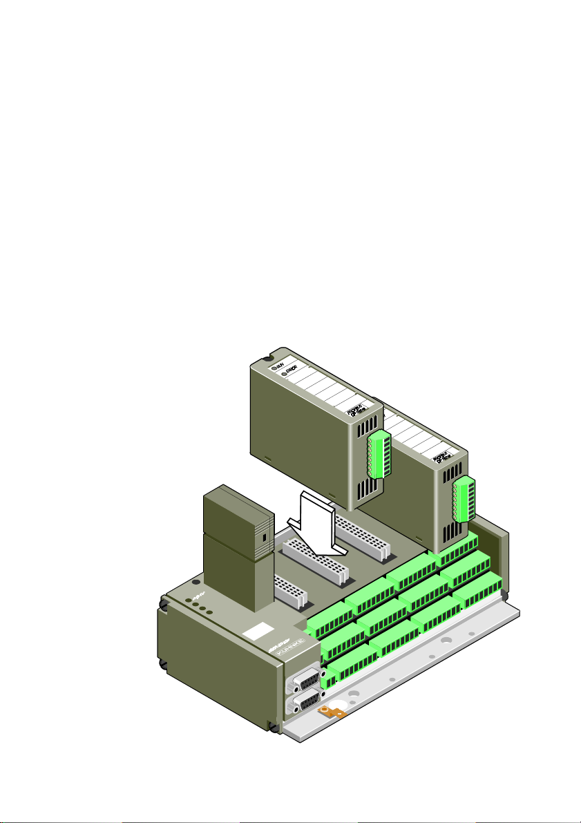
KUAX 680I, KUAX 680C and KDT 680 CT are efficient,
modularly constructed minicontrollers. They are equipped with
modules which communicate with the user program in the controller either directly or via transfer addresses (SLx...). KUAX
680C and KDT 680CT also have built-in inputs and outputs
which are not, however, described in this instruction manual.
There are connectors for three-conductor connections so that
proximity switches or other similar devices can be supplied via
the same cable as the signal line. Additional terminal strips are
thus made redundant. Simply plug the modules into the appropriate slots from above:
Fig.: KUAX 680I
Introduction
1
1 - 1
Page 12

Introduction
1.1. Manual breakdown
- Table of contents
- Chapter 1
Introduction
- Chapter 2
Some comments on the reliability of the described products
and their safe use
- Chapter 3
Basic information about application and design of the modules as well as about slots and plug connectors
- Chapter 4
Digital input and output modules
- Chapter 5
Analogue input and output modules
- Chapter 6
Counter modules and SSI module
- Chapter 7
Communication modules V.24 (RS 232), TTY (20 mA) and
RS 485, without processor
- Chapter 8
Stepper motor modules without processor
- Chapter 9
Stepper motor modules with processor
1 - 2
- Appendix A
Power supply and load characteristics of the controllers
- Appendix B
Module ordering information (summary)
- Appendix C
References to general literature and to Kuhnke instruction
manuals
- Index
Page 13

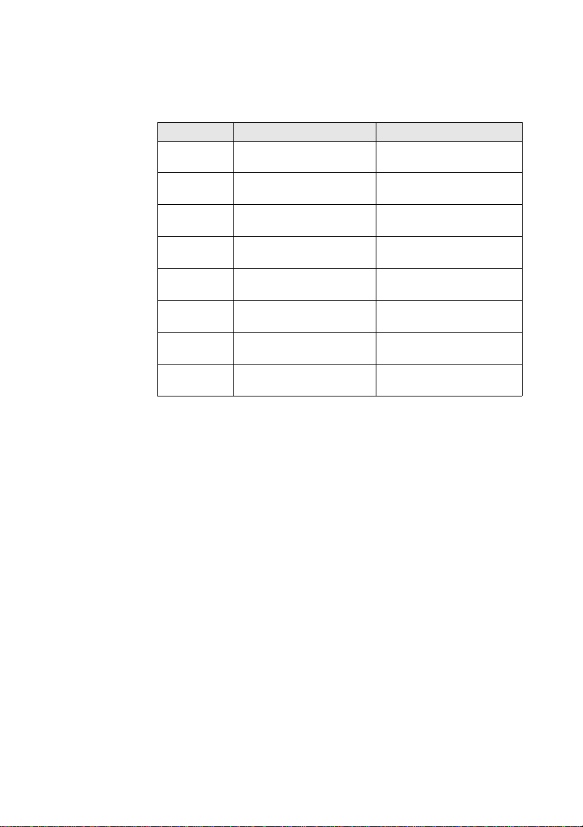
This manual only describes the modules. Please refer to the relevant instruction manuals to find out more about the actual
controllers:
Controller Instruction manual
KUAX 680I E 380 GB
KUAX 680C E 399 GB
KDT 680CT E 414 GB
1.2. Further modules
Some modules are not described in this manual but, for subject
matter reasons, have their own instruction manuals:
- PROFIBUS module 680.440.05
Instruction manual: E 509 GB
- Positioning module 680.454.06
Instruction manual: E 416 GB
- Servo counter module 680.454.05
Instruction manual: E 416 GB
Introduction
1 - 3
Page 14

Introduction
1 - 4
Page 15

2. Safety and Reliability
2.1. Target group
This instruction manual contains all information necessary for
the use of the described product (control device, software, etc.)
according to instructions. It is written for the personnel of the
construction, project planning, service and commissioning
departments. For proper understanding and error-free applica-
tion of technical descriptions, instructions for use and particularly of notes of danger and warning, extensive knowledge of
automation technology is compulsory.
2.2. Reliability
Reliability of Kuhnke controllers is brought to the highest possible standards by extensive and cost-effective means in their
design and manufacture.
These include:
selecting high-quality components,
quality arrangements with our sub-suppliers,
measures for the prevention of static charge during the handling of MOS circuits,
worst case dimensioning of all circuits,
inspections during various stages of fabrication,
computer aided tests of all assembly groups and their
coefficiency in the circuit,
statistic assessment of the quality of fabrication and of all returned goods for immediate taking of corrective action.
Safety and Reliability
Despite these measures, the occurrence of errors in electronic
control units - even if most highly improbable - must be taken
into consideration.
2 - 1
Page 16

Safety and Reliability
2.3. Notes
Please pay particular attention to the additional notes which we
have marked by symbols in this instruction manual:
2.3.1. Danger
This symbol warns you of dangers which may cause death,
(grievous) bodily harm or material damage if the described
precautions are not taken.
2.3.2. Dangers caused by high contact voltage
This symbol warns you of dangers of death or (grievous) bodily
harm which may be caused by high contact voltage if the described precautions are not taken.
2.3.3 Important information / cross reference
This symbol draws your attention to important additional information concerning the use of the described product. It may also
indicate a cross reference to information to be found elsewhere.
2 - 2
Page 17

Safety and Reliability
2.4. Safety
Our product normally becomes part of larger systems or installations. The following notes are intended to help integrating the
product into its environment without dangers for man or material/equipment.
2.4.1. To be observed during project planning and installation
- 24V DC power supply:
Generate as electrically safely separated low voltage. Suitable
devices are, for example, split transformers constructed to
correspond to European standard EN 60742 (corresponds to
VDE 0551)
- In case of power breakdowns or power fades: the program has
to be structured in such a way as to create a defined state at
restart that excludes dangerous states.
- Emergency switch-off installations or other emergency installations have to be realized in accordance with EN 60204/
IEC 204 (VDE 0113). They must be effective at any time.
- Safety and precautions regulations for qualified applications
have to be observed.
- Please pay particular attention to the notes of warning which,
at relevant places, will make you aware of possible sources of
dangerous mistakes or failures.
- The relevent standards and VDE regulations are to be observed in every case.
- Control elements have to be installed in such a way as to exclude unintended operation.
- Control cables have to be layed in such a way as to exclude
interference (inductive or capacitive) which could influence
the operation of the controller.
To achieve a high degree of conceptual safety in the planning
and installation of electronic controllers it is essential to follow the instructions given in the manual exactly because wrong
handling could lead to rendering measures against dangerous
failures ineffective or to creating additional dangers.
2 - 3
Page 18

Safety and Reliability
2.4.2. To be observed during maintenance and servicing
- Precaution regulation VBG 4.0 must be observed, and section
8 (Admissible deviations during working on parts) in particular, when measuring or checking a controller in a power-up
condition.
- Repairs must only be made by specially trained Kuhnke staff
(usually in the main factory in Malente). Warranty expires in
every other case.
- Spare parts:
Only use parts approved of by Kuhnke. Only genuine Kuhnke
modules must be used in modular controllers.
- Modules must only be connected to or disconnected from the
controller with no voltage supplied. Otherwise they may be
destroyed or (possibly not immediately recognisably!) detracted from their proper functioning.
- Always deposit batteries and accumulators as hazardous
waste.
2 - 4
Page 19

2.5. Electromagnetic compatibility
2.5.1. Definition
Electromagnetic compatibility is the ability of a device to function satisfactorily in its electromagnetic environment without
itself causing any electromagnetic interference that would be
intolerable to other devices in this environment.
Of all known phenomena of electromagnetic noise, only a certain range occurs at the location of a given device. This noise
depends on the exact location. It is determined in the relevant
product standards.
The international standard regulating construction and degree
of noise resistance of programmable logic controllers is IEC
1131-2 which, in Europe, has been the basis for European
standard EN 61131-2.
2.5.2. Resistance to interference
Safety and Reliability
Electrostatic discharge, ESD
in accordance with IEC 801-2, 3rd degree of sharpness
Fast transient interference, Burst
in accordance with IEC 801-4, 3rd degree of sharpness
Irradiation resistance of the device, HF
in accordance with IEC 801-3, 3rd degree of sharpness
Immunity to damped oscillations
in accordance with IEC 255-4 (1 MHz, 1 kV)
2 - 5
Page 20

Safety and Reliability
2.5.3. Interference emission
Interfering emission of electromagnetic fields, HF
in accordance with EN 55011, limiting value class A, group 1
If the controller is designed for use in residential districts, then
high-frequency emissions must comply with limiting value class
B as described in EN 55011.
Fitting the controller into an earthed metal cabinet and equipping the supply cables with filters are appropriate means for
keeping the corresponding limiting values.
2.5.4. General notes on installation
As component parts of machines, facilities and systems, electronic control systems must comply with valid rules and regulations, depending on the relevant field of application.
General requirements concerning the electrical equipment of
machines and aiming at the safety of these machines are contained in Part 1 of European standard EN 60204 (corresponds
to VDE 0113).
2 - 6
For safe installation of our control system please observe the
following notes:
Page 21

Safety and Reliability
2.5.5. Protection against external electrical influences
Connect the control system to the protective earth conductor to
eliminate electromagnetic interference. Ensure practical wiring
and laying of cables.
2.5.6. Cable routing and wiring
Separate laying of power supply circuits, never together with
control current loops:
DC voltage 60 V ... 400 V
AC voltage 25 V ... 400 V
Joint laying of control current loops is allowed:
data signals, shielded
analogue signals, shielded
digital I/O lines, unshielded
DC voltages < 60 V, unshielded
AC voltages < 25 V, unshielded
2 - 7
Page 22

Safety and Reliability
2.5.7. Location of installation
Make sure that there are no impediments due to temperatures,
dirt, impact, vibrations and electromagnetic interference.
Temperature
Consider heat sources such as general heating of rooms, sunlight, heat accumulation in assembly rooms or control cabinets.
Dirt
Use suitable casings to avoid possible negative influences due
to humidity, corrosive gas, liquid or conducting dust.
Impact and vibration
Consider possible influences caused by motors, compressors,
transfer routes, presses, ramming machines and vehicles.
Electromagnetic interference
Consider electromagnetic interference from various sources
near the location of installation: motors, switching devices,
switching thyristors, radio-controlled devices, welding equipment, arcing, switched-mode power supplies, converters / inverters.
2.5.8. Particular sources of interference
Inductive actuators
Switching off inductances (such as from relays, contactors, solenoids or switching magnets) produces overvoltages. It is necessary to reduce these extra voltages to a minimum.
Reducing elements my be diodes, Z-diodes, varistors or RC elements. To provide suitably designed reducing elements, we
recommend asking the manufacturer or supplier of the corresponding actuators for the relevant information.
2 - 8
Page 23
3. Modules and slots
KUAX 680I and 680C can be equipped with different types of
modules. The number of modules depends on the size of the
device:
- Devices with 4 slots: 4 modules (slots 0...3)
- Devices with 8 slots: 8 modules (slots 0...7)
(KUAX 680I only)
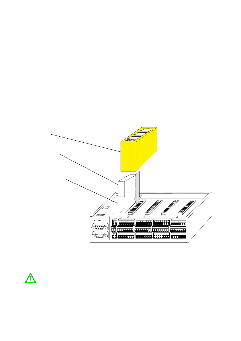
Modules are plugged into the top of the device. They are connected to the controller via the device bus plug (the figure below shows KUAX 680I):
Module
Memory module
Device bus plug
The following has to be observed when placing the modules:
- Only plug modules in/out in an idle state. Danger of destruction!
- Sequence modules from left to right (see also "3.3. Slots").
- The modules must be screwed into the device. They could otherwise become loose and then cause dangerous conditions.
3 - 1
Page 24

Modules
3.1. Design
Mounting
Labels
Status indicators
The modules are enclosed in a plastic casing. For cooling the
electronics, there are ventilation slots on the narrow edges. The
plug for the connection to the bus connector is on the bottom
side.
There is a screw sunk into the front side which is used to attach
the module to the device frame.
In KUAX 680C, KDT 680CT, and recent models of KUAX 680I
(part numbers 680.423.xx) the modules are additionally supported by plastic rests. Modules made before calendar week
27/95 do not fit into these devices because they have no bores
to place the plastic rests in.
A large area on the front side is saved for a label. The label can
be used to enter the symbolic designations of the input or output signals (cf. symbol table under KUBES) or the function of
the module.
There is a sufficient number of labels. They are delivered together with the KUAX 680I as perforated A4 tear-off blanks.
The line and column spacings are set in a way that makes an
inscription possible also for dot-matrix printers with a condensed print.
On the lefthand side of the labels there are left as many holes
as the module provides status indicators.
These holes fit across LEDs which are built into the actual
module casing to indicate, for example, signal states of inputs
or outputs.
By definition, light emitting diodes (also referred to as LEDs)
are "Class 1 light emitting diodes (in acc. with EN 60825_1)".
Channel numbers
3 - 2
On input and output modules, the corresponding channel numbers (0...3/7) are printed left to the LEDs. They correspond to
the inscription on the signal strip underneath the module. The
relation between terminal, LED and inscription is thus documented.
Page 25
3.2. Screw-type locking connectors
Screw-type locking connectors (supplied by Phoenix) are used
to connect inputs and outputs to the device:
Connector type MINI-COMBICON, 3.81 mm matrix, connecting diameter 0.14...1,5 mm² , max. load 8 A
The green screw-type locking connectors sit very firmly in
their position to avoid them becoming loose due to vibrations.
Should you find it difficult to pull them off with your fingers,
simply use a flat object such as a screwdriver with a wide blade
as a lever.
Never pull the wires to disconnect the plug. The wires might
otherwise slip out of the terminals or rip off even.
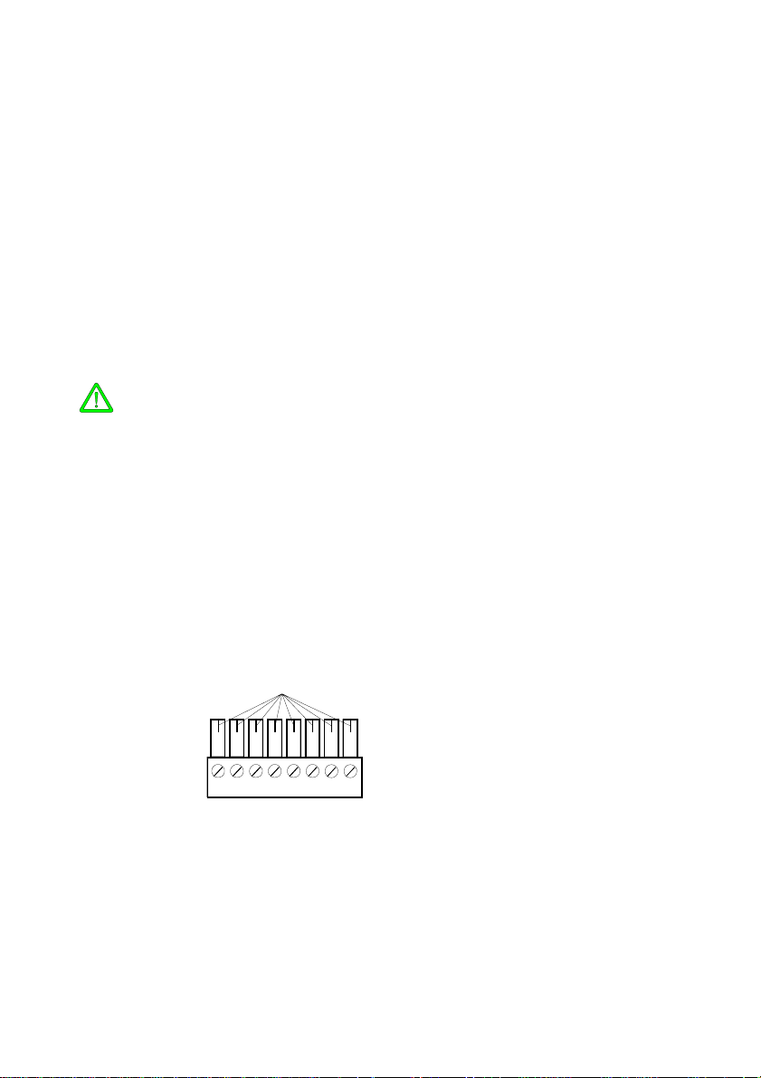
3.2.1. Coding
You can code the MINI-COMBICON connectors so that you do
not get them confused when putting them on (by conntecting
digital inputs to an SSI module, for example).
Push one or several coding profiles into the groove(s) provided
on the socket part of the connector for this purpose. Use a side
cutter, for example, to cut the corresponding coding element
off the plug part.
coding element
Kodierre i ter
Supply
There are some connectors in the basic device which are coded
in the factory. Please refer to the corresponding illustrations to
learn where such codings exist and what they look like.
3 - 3
Page 26
Modules
3.3. Slots
KUAX 680I can be equipped with slots for either 4 or 8 modules. KUAX 680C and KDT 680CT always have 4 slots (or
none).
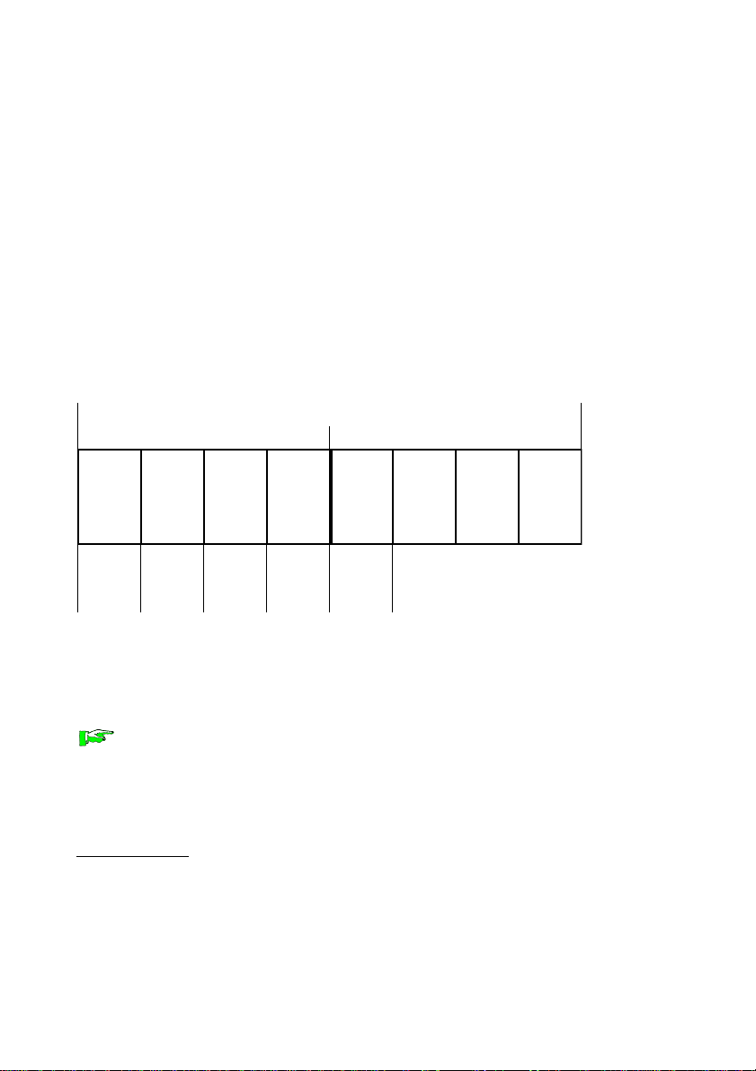
3.3.1. Function slots
Individual slots carry additional leads. They make the application of certain modules possible for using services provided by
the processor (counting, stepper motor control, analogue/digital
conversion...):
Device with 8 slots (KUAX 680I only)
Device with 4 slots
0 1 2 3 4 5 6 7
event
counter x 2
PWM x 2
analogue
input x 2
*3)
PWM x 2
*1)
analogue
input x 4
*2)
*1)
analogue
input x 4
*2)
*2)
These specifications do not limit the application of any other
module. If a function slot is not needed as such, it can also be
used for a slot-independent module such as a digital input or
output module.
*1) PWM stands for "pulse-width modulated output" for stepper motor control.
*2) This only concerns those analogue inputs with a resolution of 10bit that use the
A/D converter on the CPU.
3 - 4
Page 27

3.4. Service modules
Modules with more complex functions need software support to
be able to carry out these functions. In order to avoid the necessity for the user to write these often very complicated programs
himself, so-called service modules are embedded in the program to relieve the user.
As from release 4.00, these service modules are delivered with
KUBES as individual files under the name SERV_xx.BIN. The
KUBES installation program places these files in the same subdirectory as the program files (e.g. C:\KUBESEXE).
Configuration
When configuring KUAX 680I or 680C, you enter the modules
into a list in the same order in which they will be plugged in
later. KUBES can use this information to embed the necessary
service modules in the user program and to create the reference
to the modules.
3.4.1. Transfer address ranges
Service modules use so-called transfer address ranges (max. 32
byte) for each module for data exchange with the user program.
These are directly assigned to the module slots (see table on
next page). The service module assigned to the slot during configuration determines the assignment of the transfer addresses.
Service modules
3.4.2. Interrupt modules
Under certain conditions, some modules trigger an interrupt in
the CPU. Like this the service module, and sometimes also the
user program, can react particularly quickly to an event. An interrupt caused by a module calls up an interrupt module (see table on next page). This module can contain user-defined instructions to be carried out in case of an interrupt.
3 - 5
Page 28
Modules
Assignment of transfer addresses and interrupt modules
Slot Transfer address range Interrupt module
0
1
2
3
4
5
6
7
SLA00.00...01.15
SLB00.00...01.15
SLC00.00...01.15
SLD00.00...01.15
SLE00.00...01.15
SLF00.00...01.15
SLG00.00...01.15
SLH00.00...01.15
SLI00.00...01.15
SLJ00.00...01.15
SLK00.00...01.15
SLL00.00...01.15
SLM00.00...01.15
SLN00.00...01.15
SLO00.00...01.15
SLP00.00...01.15
10
11
12
13
14
15
16
1
2
3
4
5
6
7
8
9
3.5. Power supply of inputs and outputs
All inputs and outputs as well as the relay for polarity safeguarding in the digital output modules are centrally supplied
via the corresponding terminals of the basic device (see the relevant instruction manuals of the individual controllers).
3 - 6
Page 29

3.6. Differences between KUAX 680C/KDT 680CT and KUAX 680I
All examples given in this instruction manual refer to the use
of the relevant modules in KUAX 680I.
When working with KUAX 680C or KDT 680CT you will be
obliged to take note of some differences which are caused by
the I/Os available to the basic device.
Limited applicability
- You cannot use the counter module for event counters, order
no. 680.454.03; the reason being that in its standard configuration, the device is already equipped with two event
counters (internal inputs).
- Stepper motor modules and internal analogue outputs share
the same system resources, i.e. the PWM outputs of the processor:
PWM analogue output stepper motor module
1 AO00.00 680.444.01 and .02
2 AO00.01 680.444.02
Thus, if you are using a two-channel stepper motor module
(680.440.02) neither of the two internal analogue outputs can
be used. If you are working with a single-channel stepper
motor module (680.440.01), you still have the option of using internal analogue output AO00.01 at least.
Addressing
Please note that input and output groups are occupied already
by the internal I/Os. While plugged-in modules are numbered
in groups from left to right just like in KUAX 680I, they start
with different group numbers:
Modules first group
digital inputs I02
analogue inputs AI01
digital outputs O02
analogue outputs AO01
For further information please refer to the device manuals.
3 - 7
Page 30

Modules
3 - 8
Page 31

4. Digital inputs and outputs
Digital inputs and outputs are used for leading digital signals (1
or 0, High or Low, On or Off etc.) from the machine or system
into the controller (inputs) or vice versa (outputs).
These include:
Digital input signals from
- switches
- key-switches
- sensors
- etc.
Digital output signals for switching
- relays
- contactors
- magnetic valves
- etc.
There are only 2 possible states of digital signals:
- logical 0 (Low, Off...)
- logical 1 (High, On...)
These two signal states form the basis for most of the functions
of control engineering.
There are several digital input and output modules available for
adjusting the controller to the different types of signals.
4 - 1
Page 32

Digital inputs and outputs
4.1. Plugging digital input and output modules
As from monitor version 4.10 (KUBES version 4.01), KUAX
680I can also be equipped with 16pin modules. KUAX 680C as
from its first delivered machines.
All earlier versions of KUAX 680I only allow application of
8pin modules.
Digital input and output modules can be plugged into any slot
as long as this slot is not needed for another module (see
"3.3.1. Function slots"). Certain regulations must be regarded,
however:
4.1.1. Addressing (input/output groups and channels)
Upon switching the controller on, inputs and outputs of all
plugged-in modules are automatically numbered from left to
right in groups of 8 channels (.00... .07) each. Thus, the first in-
put group is assigned the group number I00, the second one is
assigned I01 etc. The output groups are treated in the same way
by the system: O00, O01 etc.
Example for KUAX 680I:
012 3
Legend:
4 - 2
0 input module, 8pin I00
1 output module, 8pin O00
2 input module, 16pin I01, I02
3 input/output module, 8/8pin I03, O01
Page 33

Groups
Inputs: I00...max. I15 (on 16pin modules)
Ouputs: O00...max. O07
In KUAX 680C, the first two input groups, I00 and I01, and the
first two output groups, O00 and O01, are allocated already to
the internal inputs and outputs. The modules for inputs and
outputs thus start with numbers I02 and O02.
Channels
Each group consists of 8 channels, i.e. inputs or outputs:
Inputs: Ixx.00...Ixx.07
Outputs: Oxx.00...Oxx.07
4.1.2. Reserved slots
Reserved slots for a module type of which there are modules
plugged in already (e.g. input modules) must always be located
after the last plugged-in module of the same type. Otherwise,
the module numbering (addressing) of the following modules
of the same type will change.
Addressing
Example: I I _ O
Reserved slot for an input module (I02.)
Reserved slots for later plugging of function modules or analogue input modules may also be located between modules of
one type.
Example: I _ I O
O00.
I01.
Reserved slot for a counter module
I00.
4 - 3
Page 34

Digital inputs and outputs
4.2. Digital input modules
Digital input modules are used for reading the signal states of
switches, key switches, relay contacts etc. When working with
proximity switches and semi-conductor sensors please make
sure to keep them running within the switching thresholds
given below.
Switching thresholds and filters
The input line is used to adjust the connected signals to the system voltage.
Defined signals:
Logical 0: ≤ 5 V
Logical 1: ≥ 15 V
(Hysteresis: 1...4 V)
Signal delay of inputs with normal (5ms) delay time:
In order to avoid voltage surges (noise pulses) being recog-
U[V]
24
nized as valid signals, thus executing wrong switching operations, they are filtered out.
15
layed by a nominal period of 5
ms:
Signal identification is thus de-
5
Raising delay *):
tve= 3.0 ... 7.0 ms
Signal
*) The input signals are read between individual program cycles and then written into the process image. To correctly determine the availability of the signals for the user program you would have to add
the program cycle time to the delay time.
5101520253035t[ms]
1
0
t
ve
t
va
Falling delay *):
tva= 4.0 ... 7.0 ms
4 - 4
Page 35

4.2.1. Input module, 24 V DC, 8 inputs
Signal line connection
Input voltage is 24 V DC. These signals are applied via plugscrew terminals on the signal strip underneath the module.
Input module, 8 inputs
Exx.00
Exx.01
Exx.02
Exx.03
Exx.04
Exx.05
Exx.06
Exx.07
*) read 'E' = 'I' (for Input)
*)
4 - 5
Page 36

Digital inputs and outputs
4.2.1.1. Technical specifications
Application: ............................................. KUAX 680I, 680C, 680S, KDT 680CT
Admissible ambient conditions
storage temperature ............................ -25...+70 °C
ambient temp. during operation: ....... 0...55 °C
relative humidity ................................ 50...95 %
Inputs: ....................................................... 8
Type (acc. to IEC 1131) .......................... 1
Potential separation ................................. no
Indicators .................................................. LEDs
colour .................................................. green
tapping point....................................... in the input circuit
signal states ........................................ 1: LED on
0: LED off
Addressing: .............................................. Ixx.00...Ixx.07
Input voltage: ........................................... 24 V DC -20%/+25%
(incl. residual ripple)
Surge immunity ........................................ ≤ 60 V DC (≤ 30 min.)
Signal recognition
logical 0: ............................................. ≤ 5 V DC
logical 1: ............................................. ≥ 15 V DC
Power consumption / input: .................... max. 10 mA
Weight:..................................................... c. 77 g
Part number:............................................. 680.451.01
4 - 6
Page 37

Input module, 8 inputs, with real-time clock
4.2.2. Input module, 24 V DC, 8 inputs, with real-time clock
These are the same inputs as described in chapter “4.2.1. Input
module, 24 V DC, 8 inputs” (see there for picture and connections).
Added is the function of the real-time clock which is realised
on this module.
4.2.2.1. Real-time clock
A clock module is integrated in the module which is supplied
by an accu in case of a voltage cut.
A KUBES module is available for setting and evaluating time
and date.
Name: CLOCK
Call from within the program:
JPK CLOCK
<actual time> <status indication>
<set>
The module should be called up in every PLC cycle. The program within the module is organized so as to updating the input
parameter “actual time” every second.
If there is a set command (first byte in data field “set” = 255),
the preset values are taken over immediately.
Output byte “status indication” reports any occurring errors.
4 - 7
Page 38

Digital inputs and outputs
4.2.2.2. Parameters of KUBES module “CLOCK”
The user has to reserve two data fields for the clock parameters
and one byte for status indication. It is helpful to enter these
operands into the symbol table (KUBES) at the beginning of
project planning.
The data fields must consist of subsequent operand ranges.
When programming the KUBES module, the first address of
each data field is entered.
We recommend to take over the symbols as shown in the 3 following tables:
Input parameter “Actual time”
Data field, 21 byte: current time and date (read only):
Byte
No Example Symbol
Actual value (decimal) for evaluation in the program:
1
SBM00.00 SECOND
2
SBM00.01 MINUTE
3
SBM00.02 HOUR
4
SBM00.03 WEEKDAY
5
SBM00.04 DAY
6
SBM00.05 MONTH
7
SBM00.06 YEAR
Actual value (ASCII) for transfer to text displays:
8
SBM00.07
9
SBM00.08
10
SBM00.09
11
SBM00.10
12
SBM00.11
13
SBM00.12
14
SBM00.13
15
SBM00.14
16
SBM00.15
17
SBM01.00
18
SBM01.01
19
SBM01.02
20
SBM01.03
21
SBM01.04
ASC_SEC
ASC_MIN
ASC_HOUR
ASC_WDAY
ASC_DAY
ASC_MON
ASC_YEAR
Significance
second 0...59
minute 0...59
hour 0...23
day of the week 0 (Sunday) ... 6 (Saturday)
day 1...31
month 1...12
year 0...99
second lowbyte
second highbyte
minute lowbyte
minute highbyte
hour lowbyte
hour highbyte
weekday lowbyte
weekday highbyte
day lowbyte
day highbyte
month lowbyte
month highbyte
year lowbyte
year highbyte
4 - 8
Page 39

Input parameter “Set”
Data field, 7 byte: clock flag, slot, preset time and preset date:
Input module, 8 inputs, with real-time clock
Byte
No Example Symbol
1
SBM01.05 CL_FLAG
2
SBM01.06 CL_SLOT
3
SBM01.07 SET_SEC
4
SBM01.08 SET_MIN
5
SBM01.09 SET_HOUR
6
SBM01.10 SET_WDAY
7
SBM01.11 SET_DAY
8
SBM01.12 SET_MON
9
SBM01.13 SET_YEAR
Significance
clock flag (255: write values in bytes 3...7 into the
clock)
slot number of the module (0...7)
preset value second: 0...59
preset value minute: 0...59
preset value hour: 0...23
preset value weekday: 0 (Sunday) ... 6 (Saturday)
preset value day: 1...31
preset value month: 1...12
preset value year: 0...99
Output parameter “Status indication”
1 byte: error message or OK, resp.
Byte
Example Symbol
SBM01.15 STATUS
Value Significace
0 okay message, no error
undefined clock state (no load on the accu,
identification cleared). Remedy: set the clock
1
again and recharge accu (approx. 72 h on the net)
2 set values outside the valid range
input parameters: the range of a data field is
3
exceeded
4 illegal slot number
5 6 7 8 -
4 - 9
Page 40

Digital inputs and outputs
4.2.2.3. Programming suggestion for the real-time clock
L n ;module slot (0...7)
= SBM01.06
JPK CLOCK
SBM00.00 SBM01.15
SBM01.05
L SBM01.15
CMP 0
JP<> ERROR ;for error evaluation
DISPLAY.
. ;display actual value
.
SET L Mxx.xx
= PPxx.xx
L PPxx.xx
JPCN ENDCLK ;to end of clock program
L 255
= SBM01.05
PREVAL .
. ;write preset value into oper.
. ;SET_SEC...SET_YEAR
JP ENDCLK
ERROR .
. ;error evaluation
.
ENDCLK.
. ;normal program
4 - 10
Page 41

Input module, 8 inputs, with real-time clock
4.2.2.4. Technical specifications
Application: ............................................. KUAX 680I, 680C, KDT 680CT
Admissible ambient conditions
storage temperature ............................ -25...+70 °C
ambient temp. during operation: ....... 0...55 °C
relative humidity ................................ 50...95 %
Inputs: ....................................................... 8
Type (acc. to IEC 1131) .......................... 1
Potential separation ................................. no
Indicators .................................................. LEDs
colour .................................................. green
tapping point....................................... in the input circuit
signal states ........................................ 1: LED on
0: LED off
Addressing: .............................................. Ixx.00...Ixx.07
Input voltage: ........................................... 24 V DC -20%/+25%
(incl. residual ripple)
Surge immunity ........................................ ≤ 60 V DC (≤ 30 min.)
Signal recognition
logical 0: ............................................. ≤ 5 V DC
logical 1: ............................................. ≥ 15 V DC
Power consumption / input: .................... max. 10 mA
Real-time clock: ....................................... second, minute, hour
weekday, day, month, year
Accumulator (buffering of clock)
buffer time: ......................................... ~ 3 months
charging time: .................................... ~ 72 h
Weight:..................................................... c. 85 g
Part number:............................................. 680.451.02
4 - 11
Page 42

Digital inputs and outputs
4.2.3. Input module, 24 V DC, 16 inputs
Low group number: High group number:
Status indic. (LEDs) Status indic. (LEDs)
Terminals Terminals
Signal line connection
The input voltage is 24 V DC. These signals are applied via
clamp-screw terminals. The terminals are located on the signal
strip underneath the module for the low group and on the module itself for the high group (see diagram).
4 - 12
low group number: high group number:
Exx(+1).07
Exx(+1).06
Exx(+1).05
Exx(+1).04
*)
Exx.00
Exx.01
Exx.02
Exx.03
Exx.04
Exx.05
Exx.06
Exx.07
Exx(+1).03
Exx(+1).02
Exx(+1).01
Exx(+1).00
*) read 'E' = 'I' (for Input)
*)
Page 43

Input module, 16 inputs
4.2.3. Technical specifications
Application: ............................................. KUAX 680I (as from version 4.10),
KUAX 680S (part no. 680.301.04/08)
KUAX 680C, KDT 680CT
Admissible ambient conditions
storage temperature ............................ -25...+70 °C
ambient temp. during operation: ....... 0...55 °C
relative humidity ................................ 50...95 %
Inputs: ....................................................... 16
Type (acc. to IEC 1131) .......................... 1
Potential separation ................................. no
Indicators .................................................. LEDs
colour .................................................. green
tapping point....................................... in the input circuit
signal states ........................................ 1: LED on
0: LED off
Addressing: .............................................. Ixx.00...Ixx.07
Ixx(+1).00...Ixx(+1).07
Input voltage: ........................................... 24 V DC -20%/+25%
(incl. residual ripple)
Surge immunity ........................................ ≤ 60 V DC (≤ 30 min.)
Signal recognition
logical 0: ............................................. ≤ 5 V DC
logical 1: ............................................. ≥ 15 V DC
Power consumption / input: .................... max. 10 mA
Weight:..................................................... c. 104 g
Part number:............................................. 680.451.03
4 - 13
Page 44

Digital inputs and outputs
4.2.4. Input module, 24 V DC, 8 inputs, 1 ms
These are basically the same inputs as described earlier in
chapter "4.2.1. Input module, 24 V DC, 8 inputs" (see there for
diagram and connectors).
The difference between the two modules is in the much reduced signal delay time of the module described in this chapter. This shorter signal delay makes it possible to register very
much increased signal sequences (e.g. fast counting impulses).
Please take into consideration that the shorter signal delay
time may lead to situations where noise pulses are not filtered
out and are therefore not registered by the CPU. We therefore
strongly recommend the use of shielded wires.
Signal delay:
In order to avoid voltage surges (noise pulses) being recognized as valid signals, thus executing wrong switching operations, they are filtered out.
Signal identification is thus delayed by nominally 1 ms:
U[V]
24
Raising delay*):
tve= 0.3 ... 1.0ms
Falling delay*):
15
tva= 0.4 ... 1.4ms
5
Signal
*) The input signals are read between the individual program cycles and then written into the process
image. To correctly determine the availability of the signals for the user program you would have to
add the program cycle time to the delay time.
5101520253035t[ms]
t
1
0
ve
t
va
4 - 14
Page 45

Input module, 8 inputs, 1 ms
4.2.4.1. Technical specifications
Application: ............................................. KUAX 680I, 680C, 680S, KDT 680CT
Admissible ambient conditions
storage temperature ............................ -25...+70 °C
ambient temp. during operation: ....... 0...55 °C
relative humidity ................................ 50...95 %
Inputs: ....................................................... 8
Type (acc. to IEC 1131) .......................... 1
Potential separation ................................. no
Indicators .................................................. LEDs
colour .................................................. green
tapping point....................................... in the input circuit
signal states ........................................ 1: LED on
0: LED off
Addressing: .............................................. Ixx.00...Ixx.07
Input voltage: ........................................... 24 V DC -20%/+25%
(incl. residual ripple)
Surge immunity ........................................ ≤ 60 V DC (≤ 30 min.)
Signal recognition
logical 0: ............................................. ≤ 5 V DC
logical 1: ............................................. ≥ 15 V DC
Max. voltage: ........................................... 28.8 V DC
Power consumption / input: .................... c. 10 mA
Weight:..................................................... c. 77 g
Part number:............................................. 680.451.04
4 - 15
Page 46

Digital inputs and outputs
4.2.5. Input module, 24 V DC, 16 inputs, 1 ms
These are basically the same inputs as described earlier in
chapter "4.2.3. Input module, 24 V DC, 16 inputs" (see there
for diagram and connectors).
The difference between the two modules is in the much reduced signal delay time of the module described in this chapter. This shorter signal delay makes it possible to register very
much increased signal sequences (e.g. fast counting impulses).
Please take into consideration that the shorter signal delay
time may lead to situations where noise pulses are not filtered
out and are therefore not registered by the CPU. We therefore
strongly recommend the use of shielded wires.
Signal delay:
In order to avoid voltage surges (noise pulses) being recognized as valid signals, thus executing wrong switching operations, they are filtered out.
Signal identification is thus delayed by nominally 1 ms:
U[V]
24
Raising delay*):
tve= 0.3 ... 1.0ms
Falling delay*):
15
tva= 0.4 ... 1.4ms
5
Signal
*) The input signals are read between the individual program cycles and then written into the process
image. To correctly determine the availability of the signals for the user program you would have to
add the program cycle time to the delay time.
5101520253035t[ms]
t
1
0
ve
t
va
4 - 16
Page 47

Input module, 16 inputs, 1 ms
4.2.5.1. Technical specifications
Application: ............................................. KUAX 680I (as from version 4.10),
KUAX 680S (part no. 680.301.04/08)
KUAX 680C, KDT 680CT
Admissible ambient conditions
storage temperature ............................ -25...+70 °C
ambient temp. during operation: ....... 0...55 °C
relative humidity ................................ 50...95 %
Inputs: ....................................................... 16
Type (acc. to IEC 1131) .......................... 1
Potential separation ................................. no
Indicators .................................................. LEDs
colour .................................................. green
tapping point....................................... in the input circuit
signal states ........................................ 1: LED on
0: LED off
Addressing: .............................................. Ixx.00...Ixx.07
Ixx(+1).00...Ixx(+1).07
Input voltage: ........................................... 24 V DC -20%/+25%
(incl. residual ripple)
Surge immunity ........................................ ≤ 60 V DC (≤ 30 min.)
Signal recognition
logical 0: ............................................. ≤ 5 V DC
logical 1: ............................................. ≥ 15 V DC
Power consumption / input: .................... max. 10 mA
Weight:..................................................... c. 104 g
Part number:............................................. 680.451.07
4 - 17
Page 48

Digital inputs and outputs
4.2.6. Input module, 24 V DC, 16 inputs, interrupt capability
These are basically the same inputs as described earlier in
chapter "4.2.3. Input module, 24 V DC, 16 inputs" (see there
for diagram and connectors).
The difference between the two modules is in the extended
functionality of the module described in this chapter concerning the registeration of fast input signals.
Please take into consideration that the shorter signal delay
time may lead to situations where noise pulses are not filtered
out and are therefore not registered by the CPU. We therefore
strongly recommend the use of shielded wires.
4.2.6.1. Signal delay
In order to avoid voltage surges (noise pulses) being recognized as valid signals, thus executing wrong switching operations, they are filtered out. Signal identification is thus delayed:
Inputs Ixx.00...03 (lower group, terminals underneath the module)
The first 4 outputs have interrupt
U[V]
24
capability and have a particularly short signal delay time of
nominally 0.3 ms.
15
Raising delay*):
tve= 0.09 ... 0.36ms
Falling delay*):
5
Signal
*) The input signals are read between the individual program cycles and then written into the process
image. To correctly determine the availability of the signals for the user program you would have to
add the program cycle time to the delay time.
5 1015202530 35t[ms]
t
1
0
ve
t
va
tva= 0.12 ... 0.39ms
4 - 18
Page 49

Input module, 16 inputs, interrupt capability
Inputs Ixx.04...07 (lower group, terminal underneath the module)
The next 4 outputs have a short signal delay time of nominally
1ms.
U[V]
24
Raising delay*):
tve= 0.3 ... 1.0ms
Falling delay*):
15
5
Signal
1
0
5101520253035t[ms]
t
ve
t
va
tva= 0.4 ... 1.4ms
Inputs Ixx(+1).04...07 (higher group, terminal on the module)
These 8 outputs have the normal signal delay time of nominally 5 ms.
U[V]
24
Raising delay*):
tve= 3.0 ... 7.0ms
Falling delay*):
15
tva= 4.0 ... 7.0ms
5
Signal
5101520253035t[ms]
1
0
t
ve
t
va
*) The input signals are read between the individual program cycles and then written into the process
image. To correctly determine the availability of the signals for the user program you would have to
add the program cycle time to the delay time.
4 - 19
Page 50

Digital inputs and outputs
4.2.6.2. Interrupt inputs
Inputs Ixx.00...03 (lower group, terminal underneath the module) support interrupt functions and have a particularly short
signal delay time of nominally 0.3 ms.
For enabling and registering interrupts, each module is automatically assigned a transfer address range (see "3.4. Service
modules") and an interrupt module for interrupt evaluation.
Transfer address ranges and interrupt modules
Slot Transfer address range Interrupt module
0 SLA00.00...01.15 1
1 SLC00.00...01.15 3
2 SLE00.00...01.15 5
3 SLG00.00...01.15 7
4 SLI00.00...01.15 9
5 SLK00.00...01.15 11
6 SLM00.00...01.15 13
7 SLO00.00...01.15 15
When enabled, each of the 4 inputs can trigger an interrupt in
the CPU by raising or falling signal edges. In this case, the
CPU immediately interrupts the normal program run and calls
up the interrupt module that is assigned to this module slot. In
this interrupt module you can get the information about the signal that triggered the interrupt and also start the necessary
measures. We recommend keeping the program in the interrupt
module as short as possible to avoid putting great loads on the
cycle time, especially if interrupts are used frequently.
4 - 20
The user program can also scan the status of the interrupt inputs via the normal input addresses, Ixx.00...03. This means
working with the signal delay that is extended by the cycle
time, however.
The functions of the transfer addresses are listed in the table on
the next page:
Page 51

Input module, 16 inputs, interrupt capability
Functions of the transfer addresses:
Address Symbol Function
SLx00.00
SLx00.01
SLx00.02
SLx00.03
SLx00.04
SLx00.05
SLx00.06
SLx00.07
SLx01.00
SLx01.01
SLx01.02
SLx01.03
SLx01.04
SLx01.05
SLx01.06
SLx01.07
SLx01.08
SLx01.14
SLx01.15
INT_LH_0
INT_LH_1
INT_LH_2
INT_LH_3
INT_HL_0
INT_HL_1
INT_HL_2
INT_HL_3
ENI_LH_0
ENI_LH_1
ENI_LH_2
ENI_LH_3
ENI_HL_0
ENI_HL_1
ENI_HL_2
ENI_HL_3
ENI_MOD
SET_ENI
INT_VERS
interrupt
triggered by:
positive edge
(Low->High)
interrupt
triggered by:
negative edge
(High->Low)
enable interrupt
trigger:
positive edge
(Low->High)
enable interrupt
trigger:
negative edge
(High->Low)
User program writes 255 to enable input module for processing interrupt
(0 for disabling)
User program writes 255 to transfer new settings SLx01.00...14 to CPU;
CPU acknowledges by writing 0
Software date (version) of service module
Example: Enabling the first input for interrupt H->L and L->H:
OK =1 M00.00 ;initialisation marker
Example: interrupt analysis
LH_0 L INT_LH_0 ;interrupt trigger Low->High?
HL_0 L INT_HL_0 ;interrupt trigger High->Low?
CONTINUE ...
input 00
input 01
input 02
input 03
input 00
input 01
input 02
input 03
input 00
input 01
input 02
input 03
input 00
input 01
input 02
input 03
CPU writes 255 after interrupt triggered
via this channel; user program analyses
information in interrupt module
User program writes '255' to enable
interrupt source, or '0' to disable interrupt
source.
Settings are transferred to CPU by 255 in
SLx01.14
L M00.00 ;initialisation marker
JPC OK
L 255
= ENI_MOD ;general interrupt enable
= ENI_LH_0 ;enable interrupt Low->High
= ENI_HL_0 ;enable interrupt High->Low
= SET_ENI ;transfer new settings
JPCN HL_0
... ;analysis program interrupt Low->High
CLR INT_LH_0 ;reset interrupt trigger
JPCN CONTINUE
... ;analysis program interrupt High->Low
CLR INT_HL_0 ;reset interrupt trigger
4 - 21
Page 52

Digital inputs and outputs
Interrupt frequency
Every interrupt lengthens the cycle time. If an overall program
cycle is longer than 70 ms, the monitor will trigger a watchdog
and interrupt the program run. Thus the interrupt frequency
must not exceed a maximum of 2.5 kHz for short periods of
time (approx. 10 ms). Taken over longer periods of time, the
maximum interrupt frequency must be no higher than 1 kHz. If
you are using the interrupt module as a counter you must make
sure not to exceed the interrupt frequency of 1 kHz.
4 - 22
Page 53

Input module, 16 inputs, interrupt capability
4.2.6.3. Technical specifications
Application: ............................................. KUAX 680I (as from version 4.17),
KUAX 680C, KDT 680CT
Admissible ambient conditions
storage temperature ............................ -25...+70 °C
ambient temp. during operation: ....... 0...55 °C
relative humidity ................................ 50...95 %
Inputs: ....................................................... 16
Type (acc. to IEC 1131) .......................... 1
Potential separation ................................. no
Indicators .................................................. LEDs
colour .................................................. green
tapping point....................................... in the input circuit
signal states ........................................ 1: LED on
0: LED off
Addressing: .............................................. Ixx.00...Ixx.07
Ixx(+1).00...Ixx(+1).07
Ixx.00...03 ........................................... filter 0.3 ms with interr. cap.,≤2.5 kHz
Ixx.04...07 ........................................... filter 1 ms
Ixx(+1).00...07 ................................... filter 5 ms
Input voltage: ........................................... 24 V DC -20%/+25%
(incl. residual ripple)
Surge immunity ........................................ ≤ 60 V DC (≤ 30 min.)
Signal recognition
logical 0:............................................. ≤ 5 V DC
logical 1:............................................. ≥ 15 V DC
Power consumption / input: .................... max. 10 mA
Weight:..................................................... c. 108 g
Part number:............................................. 680.451.06
4 - 23
Page 54

Digital inputs and outputs
4.3. Digital output module, 24 V DC, 0.5 A, 8 outputs
Function
Output modules provide the connection to external actuators
(relays, contactors, magnets, valves...).
Resistive and inductive loads can be connected. Freewheeling
diodes have been added to suppress inductive disable surges.
The switching state of the outputs is indicated by LEDs.
Signal line connection
The controller generates output signals of a voltage of 24 V
DC. These are picked up at the plug-screw terminals on the signal strip. Each module is assigned one block of 8 of these terminals. The block is placed directly underneath the module slot
(see diagram above).
Axx.00
Axx.01
Axx.02
*) read 'A' = 'O' (for Output)
4 - 24
*)
Axx.03
Axx.04
Axx.05
Axx.06
Axx.07
Page 55

Output module, 8 outputs
Polarity safeguard
If the connection is correct, a relay in the module switches the
supply of the outputs. A destruction of the module in case of
reversed polarity is thus avoided.
Increased performance by parallel connection
The load-carrying ability of the individual outputs is limited
(see Technical specifications). It is permissible, however, to
connect 2 outputs in parallel, thus redoubling the performance.
You must only connect outputs on the same module in parallel.
Protection against short circuit and overload
The outputs are protected against destruction by overload or
short circuit:
- the load current is limited to approx. 1.0...1.2 A
- a temperature monitor switches the output off after 0.1 to1 s
and reports a short circuit to the CPU
in KUAX 680I and 680C:
- the CPU outputs a short circuit message,
- reports short circuit by flash pulse (1) on "failure" LED,
- activates interrupt module no. 18,
- see also instruction manual KUAX 680I, E 308 GB, Appendix D.1.
in KUAX 680S:
- the CPU disables all outputs,
- reports a short circuit by flash pulse (1) on "status" LED,
- sends event notification (1) to the master via PROFIBUS
after removing the error:
- reset device (by switching it off and on)
Restart
- Search source of error
- Put controller into idle condition
- Remove error
- Supply controller with voltage
4 - 25
Page 56

Digital inputs and outputs
Backfeeding of outputs
Backfeeding means that an output is externally supplied with
voltage. This is no problem normally.
However, under certain circumstances it can destroy the freewheeling diode of the relevant output:
if
- the controller is on
- and outputs are switched on and under a load
- and if the module supply (upper terminal) is off
then
- the backfed output will use the built-in free-wheeling diode
for supply
- and the load the current may destroy the free-wheeling diode.
4.3.1 Technical specifications
Application: ............................................. KUAX 680I, 680C, 680S, KDT 680CT
Admissible ambient conditions
storage temperature ............................ -25...+70 °C
ambient temp. during operation: ....... 0...55 °C
relative humidity ................................ 50...95 %
Outputs: .................................................... 8
type ..................................................... semiconductor
Indicators .................................................. LEDs
colour .................................................. red
tapping point....................................... in the load current circuit
signal states ........................................ 1: LED on
0: LED off
Addressing: .............................................. Oxx.00...Oxx.07
Output voltage: ........................................ 24 V DC -20%/+25%
(incl. residual ripple)
Output current: ......................................... max. 0.5 A
Short circuit protection: ........................... ye s
Weight: ..................................................... c. 84 g
Part number: ............................................. 680.452.02 (older version 680.452.01)
4 - 26
Page 57

Input/output module, 8/8
4.4. Digital input/output module, 24 V DC, 8/8
Outputs: Inputs:
Status indic. (LEDs) Status indic. (LEDs)
Terminals Terminals
Function
Inputs
The inputs are the same as described in chapter "4.2.1. Input
module, 24 V DC, 8 inputs".
Outputs
The outputs are the same as described in chapter "4.3. Digital
output module, 24 V DC, 0.5 A, 8 outputs".
Signal line connection
The input signals are connected to the module via clamp-screw
terminals.
The outputs signals are connected via the signal strip underneath the module (see diagram above).
Outputs: Inputs:
Axx.00
Axx.01
Axx.02
*) read 'A' = 'O' (for output) *) read 'E' = 'I' (for input)
Exx.07
Exx.06
Exx.05
Exx.04
*)
Axx.03
Axx.04
Axx.05
Axx.06
Axx.07
Exx.03
Exx.02
Exx.01
Exx.00
*)
4 - 27
Page 58

Digital inputs and outputs
4.4.1. Technical specifications
Application: ............................................. KUAX 680I (as from version 4.10),
KUAX 680S (part no. 680.301.04/08)
KUAX 680C, KDT 680CT
Admissible ambient conditions
storage temperature ............................ -25...+70 °C
ambient temp. during operation: ....... 0...55 °C
relative humidity ................................ 50...95 %
Inputs: ....................................................... 16
Type (acc. to IEC 1131) .......................... 1
Potential separation ................................. no
Indicators .................................................. LEDs
colour .................................................. green
tapping point....................................... in the input circuit
signal states ........................................ 1: LED on
0: LED off
Addressing: .............................................. Ixx.00...Ixx.07
Input voltage: ........................................... 24 V DC -20%/+25%
(incl. residual ripple)
Surge immunity ........................................ ≤ 60 V DC (≤ 30 min.)
Signal recognition
logical 0: ............................................. ≤ 5 V DC
logical 1: ............................................. ≥ 15 V DC
Max. voltage: ........................................... 28.8 V DC
Power consumption / input: .................... max. 10 mA
Outputs: .................................................... 8
type ..................................................... semiconductor
Indicators.................................................. LEDs
colour .................................................. red
tapping point....................................... in the load current circuit
signal states ........................................ 1: LED on
0: LED off
Addressing: .............................................. Oxx.00...Oxx.07
Output voltage: ........................................ 24 V DC -20%/+25%
(incl. residual ripple)
Output current: ......................................... max. 0.5 A
Short circuit protection: ........................... yes
Weight: ..................................................... c. 117 g
Order number: .......................................... 680.450.02 (older version 680.450.01)
4 - 28
Page 59

Pneumatic output module, 4 outputs, 3/2 way
4.5. Pneumatic output module, 4 outputs 3/2 way
LED 0
LED 1
LED 2
LED 3
Circuit diagram
2.1
2.2
2.3
2.4
1
3
Outputs
Connector Function Address LED no.
2.1 pneum. output Oxx.00 LED 0
2.2 pneum. output Oxx.01 LED 1
2.3 pneum. output Oxx.02 LED 2
2.4 pneum. output Oxx.03 LED 3
1 air in - 3 air out - -
These are pneumatic outputs of 3/2 way directional control
valves. The valves are addressed by the controller like normal
digital outputs. The connection is made via the sleeve bits using 5 x 1 PE tube.
Outgoing air should always be allowed to escape from the
switching cabinet. Please note that unused outputs also give off
air so that they must either be sealed or their air out led out of
the cabinet..
4 - 29
Page 60

Digital inputs and outputs
4.5.1. Technical specifications
Application: ............................................. KUAX 680I, 680C, 680S, KDT 680CT
Admissible ambient conditions
storage temperature ............................ -25...+70 °C
ambient temp. during operation: ....... 0...55 °C
relative humidity ................................ 50...95 %
Outputs: .................................................... 4
type ..................................................... pneumatic
Indicators .................................................. LEDs
colour .................................................. red
signal states ........................................ 1: LED on
0: LED off
Addressing: .............................................. Oxx.00...Oxx.03
Valves: ...................................................... 3/2 way directional control
Switching position: .................................. normally closed (NC)
Nominal width (NW): .............................. 0.7 mm
Connector:................................................ socket for 5 x 1 PE tube
Kv value: .................................................. 0.21 l/min
please ref. to catalogue P 411 GB
Max. pressure:.......................................... P
Medium: ................................................... filtered (5 µm), oiled or filtered unoiled
≤ 7 bar
max
pressurized air. (Other gases such as
helium, argon, or CO2 can also be used.
Please feel free to contact us.)
F If you are operating a component
with oiled air once you have to make
sure to continue operating it with oiled
air as the oil will remove the initial lu-
brication.
Supply: ..................................................... shared AIR IN connector(1)
shared AIR OUT connector (3)
Switching diagram:.................................. see left side
Weight:..................................................... c. 198 g
Order number: .......................................... 680.453.01
4 - 30
Page 61

5. Analogue inputs and outputs
Analogue inputs and outputs are used to lead analogue (i.e. permanently changeable) signals from the machine or the system
into the controller (inputs) or vice versa (outputs).
These include:
Analogue signals such as
- temperature values
- liquid levels
- rotational speeds
- etc.
There is a great number of analogue modules available for the
different applications. These are described on the following
pages.
5 - 1
Page 62

Analogue inputs and outputs
5.1. Plugging analogue input and output modules
When switching the controller on, all plugged-in modules are
numbered automatically from left to right. Thus the first analogue input module is assigned the group number AI00, the
second one becomes AI01 etc. (analogue outputs: AO00.00...).
Analogue input modules with a resolution of 10 bit must only
be plugged into certain slots (see “3.3.1. Function slots”) as
they use the analogue/digital converter on the processor.
All other analogue modules can be plugged into any slot.
5.1.1. Addressing (anal. input/output groups and channels)
Upon switching on KUAX 680I, inputs and outputs of all
plugged-in modules are automatically numbered from left to
right in groups of a maximum of 4 channels (.00... .03) each.
Thus, the first analogue input group is assigned group number
AI00, the second one becomes AI01 etc. (for exceptions see ch.
"3.6. Differences between KUAX 680C/KDT 680CT...") The
analogue output groups are treated in the same way by the system: AO00, AO01 etc.
123 4
Example for KUAX 680I:
Legend:
1 analogue output module, 4pin AO00
2 analogue output module, 4pin AO01
3 analogue input/output module, 2/2pin AI00, AO02
5 - 2
4 analogue input module, 4pin AI01
Page 63

Groups
Inputs: AI00...max. AI07
Outputs: AO00...max. AO07
In KUAX 680C and KDT 680CT, the first input group, AI00,
and the first output group, AO00, are allocated to the internal
inputs and outputs. The modules for inputs and outputs thus
start with number AI01 and AO01 resp.
Channels
Each group consists of a maximum of 4 channels, i.e. inputs or
outputs:
Inputs: AIxx.00...AIxx.03
Outputs: AOxx.00...AOxx.03
5.1.2. Reserved slots
Reserved slots for a module type of which there are modules
plugged in already (e.g. input modules) must always be located
after the last plugged-in module of the same type. Otherwise,
the module numbering (addressing) of the following modules
of the same type will change.
Plugging analogue modules
Example: AI AI _ AO
Reserved slot (e.g. for an
analogue input module)
Reserved slots for later plugging of function modules or analogue input modules may also be located between modules of
one type.
Example: AI _ AI AO
AO00.
AI01.
Reserved slot (e.g. for a counter module)
AI00.
5 - 3
Page 64

Analogue inputs and outputs
5 - 4
Page 65

Analogue input modules
5.2. Analogue input modules
Analogue inputs are used to lead analogue (i.e. permanently
changeable) signals from the machine or the system into the
controller. These can be temperature values, liquid levels, rotational speeds etc.
5.2.1. Analogue input module, 0...10 V, 10 bit, 4 channels
5.2.1.1. Slots
This module uses the internal analogue/digital converter of the
processor on the CPU board. For this purpose, certain slots
carry additional leads. The module can only be operated on
these slots (see ch. “3.3. Slots”):
Slot no. Useable channels
2
3
4
*) Channels 2 and 3 cannot be used if this module is
applied to slot 2. In this case, the PWM outputs - also on
slot 1 - are switched off internally.
0, 1 *)
0, 1, 2, 3
0, 1, 2, 3
5 - 5
Page 66

Analogue inputs and outputs
5.2.1.2. Connectors
The connectors of the signal lines are located on the 8-pin
plug-screw connector underneath the module (see diagram on
previous page):
0123456
Signal (0)
Gnd (0)
Signal (1)
Gnd (1)
Signal (2)
7
Gnd (2)
Signal (3)
Gnd (3)
Both leads, signal and Gndn, must definitely be connected for
each channel (0...3). The Gndn-connections are not identical
with the device-Gnd.
Shielding
Shielded cables have to be used for connecting the analogue
signals. The shielding is connected to the aluminium
baseprofile of the controller by M3 screws (under certain circumstances, the additional grounding of the other end of the
cable may be commendable).
5.2.1.3. Representation of the analogue value
The read analogue value is digitalized and then written into a
16bit address as a two’s complement representation. This address contains the value in bits 5...14. Bits 0...4 and 15 (sign
bit) always have the status 0:
Address bit 15 14 13 12 11 10 9 8 7 6 5 4 3 2 1 0
Status 0 ------------ value read ----------- 0 0 0 0 0
In the user program, the value is read in a double-byte operation.
Example: LD AI00.00
CMPD>= 4V ;input range 0...10.00V
= M00.01
5 - 6
Page 67

Analogue input modules
5.2.1.4. Technical specifications
Application: ............................................. KUAX 680I, 680C, KDT 680CT
Admissible ambient conditions
storage temperature: ........................... -25...+70 °C
ambient temp. during operation: ....... 0...55 °C
relative humidity ................................ 50...95 %
Inputs (channels): ..................................... 4
Potential separation ................................. no
Addressing: .............................................. AIxx.00...AIxx.03
Measuring range: ..................................... 0...10 V
Resolution: ............................................... 10 bit, ~ 0.01 V / digit
Precision (relative to final value)
max. error (at 25 °C) .......................... ± 0.6 %
norm. error (at 25 °C) ........................ ± 0.3 %
temperature coefficient ...................... 0.01 % /K
linearity error ...................................... ± 0.1 %
Conversion time: ...................................... 10 ms
Input voltage protection: ......................... 60 V
Protection against noise pulses: .............. by filters and buffers
Weight ...................................................... c. 77 g
Part number:............................................. 680.441.01
5 - 7
Page 68

Analogue inputs and outputs
5.2.2. Analogue input module, 0(4)...20 mA, 10bit, 4 channels
5.2.2.1. Slots
This module uses the analogue/digital converter of the processor on the CPU. For this purpose, certain slots carry additional
leads. The module can only be operated on these slots (see
“3.3. Slots”).
5 - 8
Slot no. Useable channels
2
3
4
*) Channels 2 and 3 cannot be used if this module is
applied to slot 2. In this case, the PWM outputs - also on
slot 1 - are switched off internally.
0, 1 *)
0, 1, 2, 3
0, 1, 2, 3
Page 69

5.2.2.2. Connections
The connections of the signal lines are on the 8-pin plug-screw
connector underneath the module (see diagram on previous
page):
Analogue input modules
0123456
→←→←→←→
Signal (0)
Signal (0)
Signal (1)
Signal (1)
Signal (2)
7
←
Signal (2)
Signal (3)
Signal (3)
Shielding
Shielded cables have to be used for connecting the analogue
signals. The shielding is connected to the aluminium
baseprofile of the controller by M3 screws (under certain circumstances, the additional grounding of the other end of the
cable may be commendable).
5.2.2.3. Representation of the analogue value
The read analogue value is digitalised and then written into a
16bit address as a two’s complement representation. This address contains the value in bits 5...14. Bits 0...4 and 15 (sign
bit) always have the status 0:
Address bit 15 14 13 12 11 10 9 8 7 6 5 4 3 2 1 0
Status 0 ------------ value read ----------- 0 0 0 0 0
In the user program, the value is read in a double-byte operation.
Example: LD AI00.00
CMPD<= 8mA ;input range 0(4)...20.00mA
= M00.01
Depending on the setting of the corresponding transfer address
(see next page) the input value is defined as a 0...20mA or a
4...20mA value.
5 - 9
Page 70

Analogue inputs and outputs
5.2.2.4. Transfer address ranges
Each module is assigned a transfer address range of 16 byte
(see also "3.4. Service modules"). This range is used by the
analogue input module for data exchange with the CPU.
The address range depends on the slot:
Slot Transfer address range
2 SLE00.00...01.15
3 SLG00.00...01.15
4 SLI00.00...01.15
Assignment of transfer addresses
Address Symbol
SLx00.00
SLx00.01
SLx00.02
SLx00.03
SLx01.00
SLx01.01
SLx01.02
SLx01.03
I_SIG_0
I_SIG_1
I_SIG_2
I_SIG_3
FAIL_0
FAIL_1
FAIL_2
FAIL_3
Significance
Value Signal Chan.
0
=0
<>0
=255 wire failure 0
=255 wire failure 1
=255 wire failure 2
=255 wire failure 3
0...20 mA
4...20 mA
1
2
3
user preselects the
type of signal
(default = 0)
error message from the
service module, only
with 4...20 mA signals
5 - 10
Page 71

Analogue input modules
5.2.2.5. Technical specifications
Application: ............................................. KUAX 680I, 680C, KDT 680CT
Admissible ambient conditions
storage temperature: ........................... -25...+70 °C
ambient temp. during operation: ....... 0...55 °C
relative humidity ................................ 50...95 %
Inputs (channels): ..................................... 4
Potential separation ................................. no
Addressing: .............................................. AIxx.00...AIxx.03
Measuring range: ..................................... 0...20 mA or 4...20 mA
Resolution: ............................................... 10 bit,
~ 0.02 mA / digit for 0...20 mA
~ 0.016 mA / digit for 4...20 mA
Precision (relative to final value)
max. error (at 25 °C) .......................... ± 0.8 %
norm. error (at 25 °C) ........................ ± 0.4 %
temperature coefficient ...................... 0.02 % /K
linearity error ...................................... ± 0.1 %
Conversion time: ...................................... 10 ms
Input resistance ........................................ ~ 40 Ω
Input voltage protection: ......................... 60 V
Protection against noise pulses: .............. by filters and buffers
Indicated failures ..................................... wire failure
Weight ...................................................... c. 79 g
Part number:............................................. 680.441.02
5 - 11
Page 72

Analogue inputs and outputs
5.2.3. Analogue input module, PT100, 0...300 °C, 10 bit,
4 channels, two-wire connection
5.2.3.1. Slots
This module uses the analogue/digital converter of the processor on the CPU. For this purpose, certain slots carry additional
leads. The module can only be operated on these slots (see
“3.3. Slots”):
5 - 12
Slot no. Useable channels
2
3
4
*) Channels 2 and 3 cannot be used if this module is
applied to slot 2. In this case, the PWM outputs - also on
slot 1 - are switched off internally.
0, 1 *)
0, 1, 2, 3
0, 1, 2, 3
Page 73

5.2.3.2. Connectors
The connectors of the signal lines are located on the 8-pin
plug-screw connector underneath the module (see diagram on
previous page):
Analogue input modules
Shielding
0123456
Signal (0)
Signal (0)
Signal (1)
Signal (1)
Signal (2)
7
Signal (2)
Signal (3)
Signal (3)
Unassigned inputs put an unnecessary load on the power supply. Unused channels should therefore be terminated by 100
or should be short-circuited.
Shielded cables have to be used for connecting the analogue
signals. The shielding is connected to the aluminium
baseprofile of the controller by M3 screws (under certain circumstances, the additional grounding of the other end of the
cable may be commendable).
Ω
5 - 13
Page 74

Analogue inputs and outputs
5.2.3.3. Transfer address ranges
Each module is assigned a transfer address range of 16 byte
(see also "3.4. Service modules"). This range is used by the
analogue input module for data exchange with the CPU.
The address range depends on the slot:
Slot Transfer address range
2 SLE00.00...01.15
3 SLG00.00...01.15
4 SLI00.00...01.15
Assingment of transfer addresses
Address Symbol Significance
SLx00.00
SLx00.01 Highbyte
SLx00.02
SLx00.03 Highbyte
SLx00.04
SLx00.05 Highbyte
SLx00.06
SLx00.07 Highbyte
SLx00.08
SLx00.09
SLx00.10
SLx00.11
SLx00.12
TMP_CH0
TMP_CH1
TMP_CH2
TMP_CH3
FAIL_0
FAIL_1
FAIL_2
FAIL_3
FAIL_MOD
Lowbyte
Lowbyte
Lowbyte
Lowbyte
255 = wire failure or overtemperature channel 0
255 = wire failure or overtemperature channel 1
255 = wire failure or overtemperature channel 2
255 = wire failure or overtemperature channel 3
255 = wire failure or overtemperature in module
temperature value channel 0, 0...300.0 °C
temperature value channel 1, 0...300.0 °C
temperature value channel 2, 0...300.0 °C
temperature value channel 3, 0...300.0 °C
5 - 14
Page 75

Analogue input modules
5.2.3.4. Evaluation in the user program
There are two ways of evaluating the input information in the
user program:
As temperature value in steps of 1/10 °C
(0...3000 0...300.0 °C)
The temperature is represented as 12bit value (in 2 bytes) in the
transfer addresses (see table on previous page).
In the user program, the temperature value is read in a doublebyte operation.
Example: LD SLE00.00 ;temperature value channel 0
CMPD>= 1500 ;greater/equal 150 °C ?
= M00.01 ;set marker if so
As analogue value in a 10bit resolution
The resolution corresponds to the Kuhnke standard for analogue inputs. The temperature is represented in the 16 bit analogue input addresses (AI...). The addressing corresponds to the
sequence of the plugged-in analogue input modules (see "5.1.
Plugging analogue input and output modules").
In this address the value is in bits 5...14. Bits 0...4 and 15 (sign
bit) always have the status 0:
Address bit 15 14 13 12 11 10 9 8 7 6 5 4 3 2 1 0
Status 0 ------------ value read ----------- 0 0 0 0 0
In the user program, the value is read in a double-byte operation. Scales 0...10.00V or 0...20.00mA can be used as reference.
Example: LD AI00.00 ;analogue value channel 0
CMPD>= 5.00V ;greater/equal 150 °C?
= M00.01 ;set marker if so
5 - 15
Page 76

Analogue inputs and outputs
5.2.3.5. Technical specifications
Application: ............................................. KUAX 680I, 680C, KDT 680CT
Admissible ambient conditions
storage temperature: ........................... -25...+70 °C
ambient temp. during operation: ....... 0...55 °C
relative humidity ................................ 50...95 %
Inputs (channels): ..................................... 4
Potential separation ................................. no
Addressing:
temperature value: .............................. SLx... (0...3000 1/10 °C)
analogue value .................................... AIxx .00...AIxx.03
Measuring range: ..................................... 0...317 °C
Resolution: ............................................... 10 bit, ~ 0.31 °C / digit
Precision (relative to final value)
max. error (at 25 °C) .......................... ± 1.0 %
- up until prod. date Sept. 1996 ......... ± 1.5 %
norm. error (at 25 °C) ........................ ± 0.3 %
- up until prod. date Sept. 1996 ......... ± 1.0 %
temperature coefficient ...................... 0.03 % /K
linearity error ...................................... ± 0.2 %
Conversion time: ...................................... 10 ms
Input voltage protection: ......................... 60 V
Protection against noise pulses: .............. by filters and buffers
Indicated failures ..................................... wire failure, overtemperature
Weight ...................................................... c. 78 g
Part number:............................................. 680.441.04
5 - 16
Page 77

Analogue input modules
5.2.4. Analogue input module, thermocouple NiCrNi (type K),
0...1200 °C, 10 bit, 4 channels
This module serves registering temperature values by thermocouples. The inputs are difference inputs which are linearised
on the module. Wire failures are recognized and indicated on
the module by 4 red LEDs.
LEDs "wire failure"
Terminals
free
5.2.4.1. Slots
This module uses the analogue/digital converter of the processor on the CPU. For this purpose, certain slots carry additional
leads. The module can only be operated on these slots (see
“3.3. Slots”).
Slot no. Useable channels
2
3
4
*) Channels 2 and 3 cannot be used if this module is
applied to slot 2. In this case, the PWM outputs - also on
slot 1 - are switched off internally.
0, 1 *)
0, 1, 2, 3
0, 1, 2, 3
5 - 17
Page 78

Analogue inputs and outputs
5.2.4.2. Connections
The connections of the signal lines are on the side of the module. These are coded plug-screw connectors which can only be
plugged into this location.
Signal (0) Signal (0) +
Signal (1) Signal (1) +
Signal (2) Signal (2) +
Signal (3) Signal (3) +
The signal strip underneath the module remains unoccupied.
Open inputs put unnecessary load on the power supply. Unused
channels should therefore be short-circuited.
Shielding
Shielded cables have to be used for connecting the analogue
signals. The shielding is connected to the aluminium
baseprofile of the controller by M3 screws (under certain circumstances, the additional grounding of the other end of the
cable may be commendable).
Example for connection:
Channels 0 and 1 are connected, channels 2 and 3 are free
K
0
1
2
3
4
5
6
7
K = remove coding element
K
Signal (0) -
0
Signal (0) +
1
Signal (1) -
2
Signal (1) +
3
Signal (2) -
4
Signal (2) +
5
Signal (3) -
6
Signal (3) +
7
5 - 18
Page 79

5.2.4.3. Transfer address ranges
Each module is assigned a transfer address range of 16 byte
(see also "3.4. Service modules"). This range is used by the
analogue input module for data exchange with the CPU.
The address range depends on the slot:
Slot Transfer address range
2 SLE00.00...01.15
3 SLG00.00...01.15
4 SLI00.00...01.15
Assignment of transfer addresses
Address Symbol Significance
SLx00.00
SLx00.01 Highbyte
SLx00.02
SLx00.03 Highbyte
SLx00.04
SLx00.05 Highbyte
SLx00.06
SLx00.07 Highbyte
SLx00.08
SLx00.09
SLx00.10
SLx00.11
SLx00.12
TMP_CH0
TMP_CH1
TMP_CH2
TMP_CH3
FAIL_0
FAIL_1
FAIL_2
FAIL_3
FAIL_MOD
Lowbyte
Lowbyte
Lowbyte
Lowbyte
255 = wire failure channel 0
255 = wire failure channel 1
255 = wire failure channel 2
255 = wire failure channel 3
255 = wire failure module
temperature value channel 0, 0...1200 °C
temperature value channel 1, 0...1200 °C
temperature value channel 2, 0...1200 °C
temperature value channel 3, 0...1200 °C
Analogue input modules
5 - 19
Page 80

Analogue inputs and outputs
5.2.4.4. Evaluation in the user program
There are two ways of evaluating the input information in the
user program:
As temperature value in steps of 1 °C (0...1200 0...1200 °C)
The temperature is represented as 12bit value (in 2 bytes) in the
transfer addresses (see table on previous page).
In the user program, the temperature value is read in a doublebyte operation.
Example: LD SLE00.00 ;temperature value channel 0
CMPD> 600 ;greater 600 °C ?
= M00.01 ;set marker if yes
As analogue value in a 10bit resolution
The resolution corresponds to the Kuhnke standard for analogue inputs. The temperature is represented in the 16 bit analogue input addresses (AI...). The addressing corresponds to the
sequence of the plugged-in analogue input modules (see "5.1.
Plugging analogue input and output modules").
In this address the value is in bits 5...14. Bits 0...4 and 15 (sign
bit) always have the status 0:
Address bit 15 14 13 12 11 10 9 8 7 6 5 4 3 2 1 0
Status 0 ------------ value read ----------- 0 0 0 0 0
In the user program, the value is read in a double-byte operation. Scales 0...10.00V or 0...20.00mA can be used as reference.
Example: LD AI00.00 ;analogue value channel 0
CMPD> 5.00V ;greater 600 °C?
= M00.01 ;set marker if so
5 - 20
Page 81

Analog input modules
5.2.4.5. Technical specifications
Application: ............................................. KUAX 680I, 680C, KDT 680CT
Admissible ambient conditions
storage temperature: ........................... -25...+70 °C
ambient temp. during operation: ....... 0...55 °C
relative humidity ................................ 50...95 %
Inputs (channels): ..................................... 4
Potential separation ................................. no
Addressing: .............................................. SLx... (0...1200 °C)
Analog value ............................................ AIx x.00...AIxx.03
Measuring range: ..................................... 0...1200 °C
(linearised on the module)
Resolution: ............................................... 10 bit, ~ 1.17 °C / digit
Precision (relative to final value)
max. error (at 25 °C) .......................... ± 1.0 %
norm. error (at 25 °C) ........................ ± 0.6 %
temperature coefficient ...................... 0.02 % /K
linearity error ...................................... ± 0.2 %
Conversion time: ...................................... 10 ms
Input voltage protection: ......................... 60 V
Protection against noise pulses: .............. by filters and buffers
Wire failure monitoring........................... failures indicated by LEDs
Weight ...................................................... c. 93 g
Part number:............................................. 680.441.07
5 - 21
Page 82

Analogue inputs and outputs
5.2.5. Analogue input module, potentiometer, 10bit, 4 channels
Analogue set point modules are input modules for the connection of potentiometers which are used for presetting values for:
temperatures, liquid levels, rotation speeds, times etc.
5.2.5.1. Slots
5 - 22
This module uses the analogue/digital converter of the processor on the CPU. For this purpose, certain slots carry additional
leads. The module can only be operated on these slots (see
“3.3. Slots”).
Slot no. Useable channels
2
3
4
*) Channels 2 and 3 cannot be used if this module is
applied to slot 2. In this case, the PWM outputs - also on
slot 1 - are switched off internally.
0, 1 *)
0, 1, 2, 3
0, 1, 2, 3
Page 83

5.2.5.2. Connectors
The connections for the potis are on the 8-pin plug-screw connector underneath the module. The supply (10V) is generated
in the power pack of the control (system voltage):
Analogue input modules
0123456
+10V
+10V
Potentiometer
Power supply
Signal (0)
Signal (1)
Signal (2)
7
Gnd
Gnd
Signal (3)
Potentiometer
Power supply
Shielding
Shielded cables have to be used for connecting the analogue
signals. The shielding is connected to the aluminium
baseprofile of the controller by M3 screws (under certain circumstances, the additional grounding of the other end of the
cable my be commendable).
Example for the connections of channel 0:
0 1 2 3 4 5 6 7
5 - 23
Page 84

Analogue inputs and outputs
5.2.5.3. Representation of the analogue value
The read analogue value is digitalised and then written into a
16bit address as a two’s complement representation. This address contains the value in bits 5...14. Bits 0...4 and 15 (sign
bit) always have the status 0:
Address bit 15 14 13 12 11 10 9 8 7 6 5 4 3 2 1 0
Status 0 ------------ value read ----------- 0 0 0 0 0
In the user program, the value is read in a double-byte operation.
Example: LD AI00.00
CMPD<= 5V ( 50%)
= M00.01
5 - 24
Page 85

Analogue input modules
5.2.5.4. Technical specifications
Application: ............................................. KUAX 680I, 680C, KDT 680CT
Admissible ambient conditions
storage temperature: ........................... -25...+70 °C
ambient temp. during operation: ....... 0...55 °C
relative humidity ................................ 50...95 %
Inputs (channels): ..................................... 4 potentiometer inputs
Potential separation ................................. no
Addressing: .............................................. AIxx.00...AIxx.03
Potentiometer scale: ................................ 4.7 kΩ ... 1 kΩ
Load resistance: ....................................... 4.7 kΩ min.
Total load / module .................................. 8.5 mA max.
Measuring range: ..................................... 0...10 V
Resolution: ............................................... 10 bit, ~ 0.01 V / digit
Precision (relative to final value)
max. error (at 25 °C) .......................... ± 0.6 %
norm. error (at 25 °C) ........................ ± 0.3 %
temperature coefficient ...................... 0.02 % /K
linearity error ...................................... ± 0.1 %
Conversion time: ...................................... 10 ms
Input voltage protection: ......................... 60 V
Protection against noise pulses: .............. by filters and buffers
Weight ...................................................... c. 78 g
Part number:............................................. 680.441.05
5 - 25
Page 86

Analogue inputs and outputs
5 - 26
Page 87

Analogue output modules
5.3. Analogue output modules
Analogue outputs are lead from the controller into the machine
or system. They may include: temperature values, liquid levels,
speed settings etc.
5.3.1. Analogue output module, 0...10 V, 8 bit, 4 channels
5.3.1.1. Slots
This module has its own digital-to-analogue converter. It can
therefore be plugged into any slot of the controller.
5 - 27
Page 88

Analogue inputs and outputs
5.3.1.2. Connectors
The connectors of the signal lines are on the 8-pin plug-screw
connector underneath the module (see diagram on previous
page):
Signal (0)
Gnd (0)
Signal (1)
Gnd (1)
Signal (2)
Gndl (2)
Signal (3)
Gnd (3)
0
1
K
2
3
4
5
6
7
K = remove coding element
K
Both wires, signal and Gndn, must be connected for each channel. The Gndn connections are not identical with the device's
Gnd.
Shielding
Shielded cables have to be used for connecting the analogue
signals. The shielding is connected to the aluminium
baseprofile of the controller by M3 screws (under certain circumstances, the additional grounding of the other end of the
cable may be commendable).
5.3.1.3. Repesentation of the analogue value
5 - 28
The read analogue value is digitalized and written into a 16 bit
address as a two's complement representation. In the address,
the value is in bits 7...14. Bits 0...6 are not evaluated, bit 15
(sign bit) always has the status 0:
Address bit: 15 14 13 12 11 10 9 8 7 6 5 4 3 2 1 0
Status: 0 -------output value------- x x x x x x x
In the user program, the value is entered in a double-byte operation.
Page 89

Analogue output modules
Example: LD 5.5V ;input range 0...10.00V
=D AO00.00
5.3.1.4. Technical specifications
Application: ............................................. KUAX 680I, 680C, KDT 680CT
Admissible ambient conditions
storage temperature: ........................... -25...+70 °C
ambient temp. during operation: ....... 0...55 °C
relative humidity ................................ 50...95 %
Outputs (channels): .................................. 4, short-circuit prot., single-ended
Short-circuit current................................. 15 mA max.
Potential separation ................................. no
Addressing: .............................................. AOxx.00...AOxx.03
Range: ...................................................... 0...10 V
Burden ...................................................... 2 kΩ min.
Resolution: ............................................... 8 bit, ~ 0.04 V / digit
Transient building-up period ................... norm. 0.05 ms
Precision (relative to final value)
max. error (at 25 °C) .......................... ± 1.0 %
norm. error (at 25 °C) ........................ ± 0.5 %
temperature coefficient ...................... 0.02 % /K
linearity error ...................................... ± 0.4 %
Weight ...................................................... c. 85 g
Part number:............................................. 680.442.01
5 - 29
Page 90

Analogue inputs and outputs
5 - 30
Page 91

Analogue output modules
5.3.2. Analogue output module, 0(4)...20 mA, 8bit, 4 channels
5.3.2.1. Slots
This module has its own digital-to-analogue converter. It can
therefore be plugged into any slot of the controller.
5 - 31
Page 92

Analogue inputs and outputs
5.3.2.2. Connectors
The connectors of the signal lines are on the 8-pin plug-screw
connector underneath the module (see diagram on previous
page):
←
Signal (0)
→
Signal (0)
←
Signal (1)
→
Signal (1)
←
Signal (2)
→
Signal (2)
←
Signal (3)
→
Signal (3)
Shielding
Shielded cables have to be used for connecting the analogue
signals. The shielding is connected to the aluminium
baseprofile of the controller by M3 screws (under certain circumstances, the additional grounding of the other end of the
cable may be commendable).
0
1
K
2
3
4
5
6
7
K = remove coding element
K
5.3.2.3. Repesentation of the analogue value
The read analogue value is digitalised and written into a 16 bit
address as a two's complement representation. In the address,
the value is in bits 7...14. Bits 0...6 are not evaluated, bit 15
(sign bit) always has the status 0:
Address bit: 15 14 13 12 11 10 9 8 7 6 5 4 3 2 1 0
Status: 0 -------output value------- x x x x x x x
5 - 32
Page 93

Analogue output modules
In the user program, the value is entered in a double-byte operation.
Example: LD 10 mA ;input range 0(4)...20 mA
=D AO00.00
Depending on the setting of the corresponding transfer address
(see below), the input value is defined as 0...20 or 4...20mA
value.
5.3.2.4. Transfer address ranges
Each module is assigned a transfer address range of 32 byte
(see also "3.4. Service modules"). The first group of this range
is used by the analogue output module to determine the range
of the output signal.
The address range depends on the slot:
Slot Transfer address range
0 SLA00.00...01.15
1 SLC00.00...01.15
2 SLE00.00...01.15
3 SLG00.00...01.15
4 SLI00.00...01.15
5 SLK00.00...01.15
6 SLM00.00...01.15
7 SLO00.00...01.15
Assignment of transfer addresses
Address Symbol
SLx00.08
SLx00.09
SLx00.10
SLx00.11
O_SIG_0
O_SIG_1
O_SIG_2
O_SIG_3
Value Signal Chan.
=0
<>0
0...20 mA
4...20 mA
Significance
0
User preselects the type
1
of signal
2
(default = 0)
3
5 - 33
Page 94

Analogue inputs and outputs
5.3.2.5. Technical specifications
Application: ............................................. KUAX 680I, 680C, KDT 680CT
Admissible ambient conditions
storage temperature: ........................... -25...+70 °C
ambient temp. during operation: ....... 0...55 °C
relative humidity ................................ 50...95 %
Outputs (channels): .................................. 4
Potential separation ................................. no
Addressing: .............................................. AOxx.00...AOxx.03
Range: ...................................................... 0(4)...20 mA
Resolution: ............................................... 8 bit,
~ 0.08 mA / digit for 0...20 mA
~ 0.06 mA / digit for 4...20 mA
Transient building-up period ................... norm. 0.015 ms
Precision (relative to final value)
max. error (at 25 °C) .......................... ± 1.0 %
norm. error (at 25 °C) ........................ ± 0.5 %
temperature coefficient ...................... 0.02 % /K
linearity error ...................................... ± 0.4 %
No-load voltage ....................................... 15 V max.
Burden: ..................................................... 600 Ω max.
Weight ...................................................... c. 86 g
Part number:............................................. 680.442.02
5 - 34
Page 95

Analogue input/output modules
5.4. Analogue input/output modules
These modules have analogue inputs and analogue outputs.
They are mainly used in cases where only a small amount of
channels is required.
5.4.1. Analogue I/O module, 2 I 0...10 V, 2 O 0...±10V
Inputs: 0...10 V, 10 bit, 2 channels
Outputs: -10...0...+10 V, 12 bit, 2 channels
5 - 35
Page 96

Analogue inputs and outputs
5.4.1.1. Slots
Analogue inputs
This module uses the analogue-to-digital converter of the processor on the CPU for the analogue inputs. For this purpose, certain slots carry additional leads. If the analogue inputs are used,
then the module can only be operated on these slots (see "3.3.
Slots”):
Slot no. Useable channels
2
3
4
As there are only 2 analogue inputs the module should preferably be plugged into slot 2 as long as this is not occupied already.
Analogue outputs
The digital-to-analogue converter can convert 12bit digital values (including signs).
If only the analogue outputs of the module are to be used, then
the module can also be plugged into any other slot.
0, 1
0, 1
0, 1
5 - 36
Page 97

5.4.1.2. Connectors
Analogue inputs
The connections of the signal lines for the analogue inputs are
on the 8-pin plug-screw connector underneath the module:
Analogue input/output modules
Analogue outputs
Shielding
0123456
Signal (0)
Gnd (0)
Signal (1)
Gnd (1)NCNCNCNC
7
Both leads, signal and Gndn, must definitely be connected for
each channel. The Gndn-connections are not identical with the
device-Gnd.
The connections of the signal lines for the analogue outputs are
on the side of the module. A 4-pin plug-screw connector (5.08
mm grid) is used, which is delivered together with the module.
Signal (0)
Gnd (0)
Signal (1)
Gnd (1)
Shielded cables have to be used for connecting the analogue
signals. The shielding is connected to the aluminium
baseprofile of the controller by M3 screws (under certain circumstances, the additional grounding of the other end of the
cable may be commmendable).
5 - 37
Page 98

Analogue inputs and outputs
5.4.1.3. Representation of the analogue value
Analogue inputs
The read analogue value is digitalized and then written into a
16bit address as a two’s complement representation. In this address, the value is in bits 5...14. Bits 0...4 and 15 (sign bit) always have the status 0:
Address bit 15 14 13 12 11 10 9 8 7 6 5 4 3 2 1 0
Status 0 ------------ value read ----------- 0 0 0 0 0
In the user program, the value is read in a double-byte operation.
Example: LD AI00.00
CMPD< 5.5V ;input range 0...10.00V
= M00.01
Analogue outputs
The analogue value to be output must be written into a 16bit
address as a two’s complement representation by the user program. In this address, the value is in bits 4...14 and the sign in
bit 15. Bits 0...3 are not evaluated.
Address bit 15 14 13 12 11 10 9 8 7 6 5 4 3 2 1 0
Status ± ------------ output value ------------- x x x x
In the user program, the value is written in a double-byte operation.
Example: LD 5.5V ;input range 0...±10.00V
=D AO00.00
5 - 38
Page 99

Analogue input/output modules
5.4.1.4. Technical specifications
Application: ............................................. KUAX 680I, 680C, KDT 680CT
Admissible ambient conditions
storage temperature: ........................... -25...+70 °C
ambient temp. during operation ........ 0...55 °C
relative humidity ................................ 50...95 %
Inputs ........................................................ 2
Potential separation ................................. no
Addressing: .............................................. AIxx.00...AIxx.01
Measuring range: ..................................... 0...10 V
Resolution: ............................................... 10bit, ~ 0.01 V / digit
Precision (relative to final value)
max. error (at 25 °C) .......................... ± 0.6 %
norm. error (at 25 °C) ........................ ± 0.3 %
temperature coefficient ...................... 0.01 % /K
linearity error ...................................... ± 0.1 %
Conversion time: ...................................... 10 ms
Input voltage protection: ......................... 60 V
Protection against noise pulses: .............. by filters and buffers
Outputs ..................................................... 2, short-circuit protected
Potential separation: ................................ no
Addressing: .............................................. AOxx.00...AOxx.01
Range: ...................................................... -10...0...+10 V
Max. output current: ................................ 5 mA max, 10 nF
Resolution: ............................................... 11bit + sign, ~ 0.005 V / digit
Transient building-up period: .................. norm. 0.07 ms
Burden: ..................................................... 2 kΩ min.
Short circuit current: ................................ 15 mA max.
Precision (relative to final value)
max. error (at 25 °C) .......................... ± 0.4 %
norm. error (at 25 °C) ........................ ± 0.1 %
temperature coefficient ...................... 0.01 % /K
linearity error ...................................... ± 0.1 %
Sign: ......................................................... 1bit
Weight:..................................................... c. 98 g
Part number:............................................. 680.441.03
5 - 39
Page 100

Analogue inputs and outputs
5.4.2. Analogue I/O module, 2 I 0...20 mA, 2 O 0...±10V
Inputs: 0(4)...20 mA, 10 bit, 2 channels
Outputs: -10...0...+10 V, 12 bit, 2 channels
5.4.2.1. Slots
Analogue inputs
This module uses the analogue-to-digital converter on the processor of the CPU for the analogue inputs. For this purpose, certain slots carry additional leads. If the analogue inputs are used,
then the module can only be operated on these slots (see 3.3.
Slots”).
5 - 40
Slot no. Useable channels
2
3
4
As there are only 2 analogue inputs the module should preferably be plugged into slot 2 as long as this is not occupied already.
0, 1
0, 1
0, 1
 Loading...