

Page 1
ASSEMBLY / OPERATOR'S
MANUAL
WMU 210 / 230 / 265 / 305
N° 95603 B.GB - 05.96
SHREDDERS
PLEASE READ CAREFULLY
BEFORE USING THE MACHINE
Page 2

DEAR OWNER,
In buying a KUHN machine you have chosen wisely. Into it have gone years of thought,
research and improvements. You will find, as have thousands of owners all over the world, that
you have the best that engineering skill and actual field testing can produce. You have
purchased a dependable machine, but only by proper care and operation can you expect to
receive the performance and long service built into it.
This manual contains all the necessary information for you to receive full efficiency from your
machine. The performance you get from this machine is largely dependant upon how well you
read and understand this manual and apply this knowledge. Please DO NOT ASSUME THAT
YOU KNOW HOW TO OPERATE AND MAINTAIN YOUR MACHINE before reading this
manual carefully. KEEP THIS MANUAL AVAILABLE FOR REFERENCE.
Your KUHN dealer will instruct you on the general operation of your machine. He is interested
that you get the best performance possible and will be glad to answer any special questions
that may arise regarding the operation of the KUHN machine.
Your KUHN dealer can offer a complete line of genuine KUHN service parts.
These parts are manufactured and carefully inspected in the same factory that builds the
machine to assure high quality and accurate fitting of any necessary replacements.
When ordering service parts it is important that you indicate the type of machine concerned
and its serial number.
For this reason please complete the model identification plate diagram below with the required
information. This will provide you with an easy reference for future service parts orders.
ABOUT IMPROVEMENTS
KUHN is continually striving to improve its products and, therefore, reserves the right to make
improvements or changes when it becomes practical to do so, without incurring any
obligations to make changes or additions to the equipment sold previously.
Page 3

CONTENTS
Page
Safety 2
Safety decals 7
Technical specifications 10
Machine loading-unloading instructions 11
Fitting instructions and adjustments 12
Parking the machine 16
Adapting to the tractor 17
Machine offsetting 18
P.T.O. Shaft 19
Rotor speed 20
Optional accessories : 21
Collecting rake 21
Rear gauge wheels 21
Hydraulic parallelogram offsetting 21
Maintenance 22
Lubrication 22
Belt tension 23
Hammer knives fitting 24
Hammer knives wear and fixation pin control 26
Operating advice 28
Trouble shooting guide 29
Limited warranty 30
Copyright 1996 KUHN S.A.
- 1 -
Page 4

SAFETY
The symbol above is used throughout this manual every time recommendations are made concerning your safety,
the safety of others, or the good operation of the machine.
These recommendations must be made known to all machine operators.
DESIGNATED USE OF THE MACHINE
The WMU 210, 230, 265 or 305 shredders must only be used for the work for which they have been
designed : shredding of vegetable residues such as grass, small brush, light orchard wood and wine shoots.
The manufacturer is not held liable for any damage resulting from machine applications other than those specified
by the manufacturer.
Any use other than the designated operation is at the risk and responsibility of the operator.
Designated use of the machine also means :
- following operation, maintenance and repair recommendations given by the manufacturer ;
- using only genuine spare parts, equipment and accessories as designated by the manufacturer.
The WMU 210, 230, 265 or 305 shredders must only be operated, maintained and repaired by competent persons
who are familiar with machine specifications and operation and are aware of any danger involved.
The operator must imperatively respect current legislation concerning :
- accident prevention,
- work safety,
- public traffic circulation.
All safety advice indicated on the machine must be strictly observed.
The manufacturer is not held liable for any damage resulting from machine modifications carried out by the operator
himself or by a third party without previous written agreement from the manufacturer.
GENERAL SAFETY RECOMMENDATIONS
Before operating the machine, always ensure that tractor and machine are in accordance with work safety and road
traffic regulations.
BASIC PRINCIPLES
1. In addition to the recommendations given in this manual, legislation on work safety and accident prevention
must also be respected.
2. Advice is indicated on the machine, specifying safety recommendations in order to prevent accidents.
3. Before travelling on public roads, the operator must ensure that the machine conforms to road traffic regulations.
- 2 -
Page 5

4. Before starting work, the operator must be familiar with all machine controls, handling devices and their
functions. Once at work, it is too late to do so !
5. Do not wear loose clothing which could become caught up in moving elements.
6. Use a tractor equipped with a safety cab. Keep windows and roof hatch closed for reduced sound level while
operating the PTO driven implement.
7. Before starting up the machine and beginning work, check the surrounding area (beware of children !). Make
sure there is sufficient visibility.
Keep all people and animals away from the danger zone of the machine (risk of projection !)
8. Carrying people or animals on the machine when working or in transport is strictly forbidden.
9. Machine must only be attached to tractor using means provided and in accordance with current safety
standards.
10. When attaching or removing the machine, place the parking stand into the corresponding position.
11. Special care should be taken when attaching or removing the machine from the tractor.
12. Before attaching the machine, ensure that the front tractor axle is sufficiently ballasted.
Ballast is to be placed on the supports provided in accordance with instructions of the tractor manufacturer.
13. Do not surpass the maximum axle load or the overall transport weight as prescribed by the tractor manufacturer.
14. Do not surpass the maximum transport width authorized by road traffic regulations.
15. Before transporting the machine on public roads, ensure that all legally required guards and indicators (lights,
reflectors ...) are in place and in good operation.
16. All operating controls (cords, cables, rods...) must be positioned so that they cannot be set off accidently,
risking accident or damage.
17. Before transporting on public roads, locate the machine into its transport position as instructed in this
operators manual.
18. Never leave the tractor seat while the machine is operating.
19. Drive speed must be adapted to ground conditions as well as roads and paths.
Always avoid abrupt changes of direction.
20. Precision steering, tractor adherence, road holding and efficient braking are influenced by the type of
implement, weight, ballast of front axle, ground or road conditions. It is therefore of utmost importance to be
cautious in every given situation.
21. Be particularly cautious when turning corners, paying attention to machine overhang, length, height and weight.
22. Before operating the machine, ensure that all safety guards are firmly in place and in good condition. If worn
or damaged, replace immediately.
23. Before operating the machine, check tightness of nuts and bolts, particularly on fixing elements (blades, tines,
knives, spades ...).
- 3 -
Page 6

24. Keep clear of the machine operating area.
25. WARNING ! Danger of crushing and shearing can exist when components are operated by hydraulic or
pneumatic controls.
26. Before leaving the tractor or before adjusting, maintaining or repairing the machine, turn off the engine, remove
ignition key and wait until all moving parts have come to a complete stop.
27. Do not stand between the tractor and the machine unless the hand brake is tight and/or stops have been placed
under the wheels.
28. Before any adjustments, maintenance or repairs are carried out, ensure that the machine cannot be started
up accidentally.
ATTACHMENT
1. When attaching or removing the machine from the tractor, position hydraulic lift control lever in such a way that
it cannot be set off accidentally.
2. When attaching the machine to tractor hydraulic linkage, ensure that diameter of link pins corresponds to
diameter of ball joints.
3. WARNING ! Danger of crushing and shearing can exist in the lifting zone of the tractor hydraulic linkage !
4. Do not stand between the tractor and the machine when operating the outer control lever of the lift mechanism.
5. In transport, the machine lift mechanism should be stabilized by tractor tie rods to avoid floatation and side shifting.
6. When transporting machine ensure that it can not be lowered accidentally.
POWER TAKE-OFF
1. Only use PTO shaft supplied with the machine or recommended by the manufacturer.
2. PTO guards must always be in place and in good condition.
3. Check for correct PTO overlap when at work and in transport.
4. Before attaching or removing the PTO shaft, disengage PTO shaft, turn off engine and remove ignition key.
5. If a primary PTO shaft is equipped with a slip clutch or a free wheel, these must be fitted on the machine
PTO.
6. Ensure that PTO shaft is always correctly fitted and locked into place.
7. Make sure guards are correctly in place and secured with the safety chains provided.
8. Before engaging PTO, ensure that PTO speed and direction are in accordance with manufacturer's
recommendations.
9. Before engaging PTO, keep all people and animals clear from the machine.
10. Never engage PTO shaft when tractor engine is turned off.
11. Never surpass PTO angle recommended by the manufacturer.
- 4 -
Page 7

12. WARNING ! Rotating elements can continue turning momentarily after PTO is disengaged. Keep clear until
all rotating elements are at a standstill.
13. When removing the machine, locate PTO shaft on the supports provided.
14. Fit safety cap on tractor PTO.
15. Replace any worn or damaged PTO guards immediately.
HYDRAULIC SYSTEM
1. WARNING ! Hydraulic system is under pressure.
2. When fitting hydraulic motors or cylinders, ensure that connections have been made correctly, as per
manufacturers instructions.
3. Before connecting hoses to the tractor hydraulics, ensure that tractor and machine circuits are not under
pressure.
4. It is strongly recommended that the operator marks the hydraulic connections between tractor and machine to
avoid making a wrong connection. WARNING ! Functions could be reversed (for example : lift/lower).
5. Check hydraulic hoses regularly ! Worn or damaged hoses must be replaced immediately.
Replacement parts must be in accordance with manufacturers recommendations concerning specifications
and quality.
6. Should a leak be found, take all necessary precautions to avoid accidents.
7. Any liquid under pressure (particularly oil from hydraulics) can penetrate the skin and cause severe injury. If
injured, see a doctor immediately, there could be danger of infection.
8. Before any adjustments, maintenance or repairs are carried out, lower the machine, depressurize the circuit,
turn off the engine and remove ignition key.
MAINTENANCE
1. Before checking any machine malfunction and before adjusting, maintaining or repairing the machine,
disengage PTO, turn off engine and remove ignition key.
2. Check tightness of nuts and bolts regularly. Retighten if necessary.
3. If the machine is raised, prop it up in a stable position before carrying out any maintenance work.
4. When replacing a working part, wear protection gloves and only use standardized tools.
- 5 -
Page 8

5. It is forbidden to discard any oil, grease or filters. These must be given to waste disposal organisations to
protect the environment.
6. Disconnect power source before any work is done on the electric system.
7. Check safety guards regularly, particularly those that are subject to wear. Replace immediately if damaged.
8. Spare parts used must be in accordance with specifications and standards as defined by the manufacturer.
Use only genuine KUHN parts !
9. Before any electric welding is carried out on tractor or attached machine, disconnect generator and battery
terminals.
10. Repairs on elements under pressure or tension (springs, accumulators etc...) must only be carried out by
competent persons with standardized equipment.
SPECIAL SAFETY RECOMMENDATIONS
1. Use a tractor equipped with an enclosed cab with windows made of safety glass and kept closed. It is
recommended to fit polycarbonate screens inside the tractor safety cab's side and rear windows or to install
mesh guards on the exterior of them.
2. Stay a safe distance away from the shredder when rotor is rotating.
3. Each time before using the shredder, inspect condition of cutting elements. Replace any missing, worn or
damaged cutting elements immediately. Use only genuine KUHN spare parts.
4. When replacing cutting elements, systematically inspect their securing elements as per the manufacturers
recommendations.
5. Protection devices are intended to prevent stones, rocks or other foreign objects from being projected. They also
prevent access to the machines danger zones. Therefore, it is imperative that protection devices are put in place
and properly secured each time before using the machine.
6. PTO drive to the shredder must never be engaged unless the machine is in contact with the ground.
7. Even when the machine is used in accordance with it purpose, objects may be projected. It is therefore imperative
that everyone be kept away from the danger zone, that extra care be taken and that extra precaution (such as
safety indicators) be taken when mowing pastures alongside roads or near public areas (parks, schools etc.).
8. Never work in reverse.
9. When disengaging the PTO drive, moving parts continue to rotate for some time. Wait for all moving parts to
come to a complete stop before approaching the machine.
10. If an obstruction is hit, stop the tractor immediately, disengage PTO drive, turn off engine, remove ignition key
and wait for all moving parts to come to a complete stop.
Check the entire machine for any damage before resuming work.
11. It is strongly recommended to have your machine checked by your dealer after each season, especially cutting
elements and their fixing devices.
- 6 -
Page 9
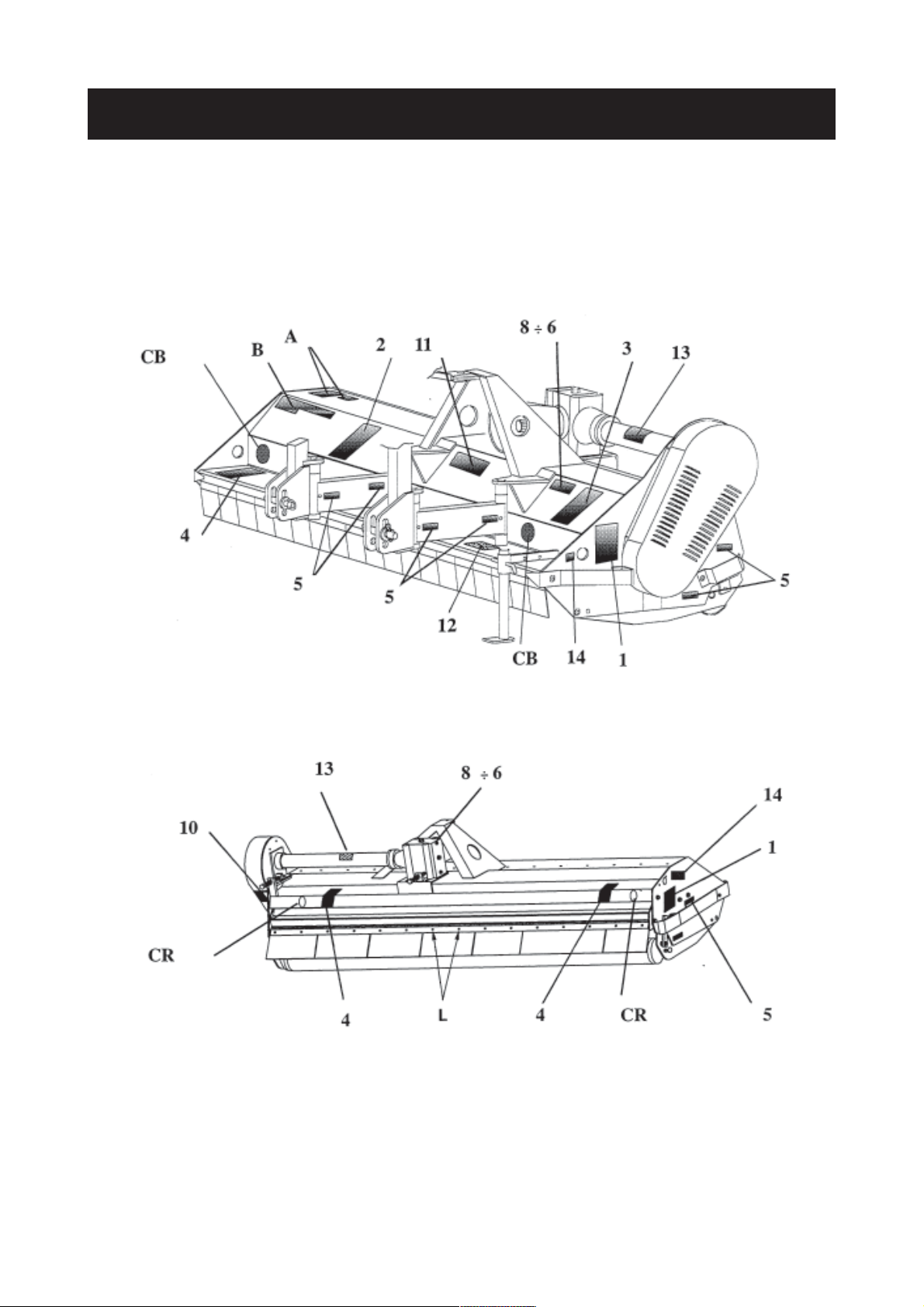
SAFETY DECALS
THE FOLLOWING SAFETY PICTORIALS HAVE BEEN PLACED ON YOUR MACHINE IN THE AREAS
INDICATED. THEY ARE INTENDED FOR YOUR PERSONAL SAFETY AND FOR THE SAFETY OF THE
PEOPLE WORKING WITH YOU. THE TEXT SHOWN ON THEM GIVES THEIR PRECISE MEANING.
KEEP THE PICTORIALS LEGIBLE. IF THEY ARE NOT, REPLACE THEM.
To protect the user of the machine, and also any other person, the rear cover of the machine is fitted with a number
of rubber segments which prevent the ejection of stones or other objects.
To replace any damaged segments, unscrew the bolts (L) and remove downwards the damaged portion so as to
remove it from the mounting bar.
- 7 -
Page 10
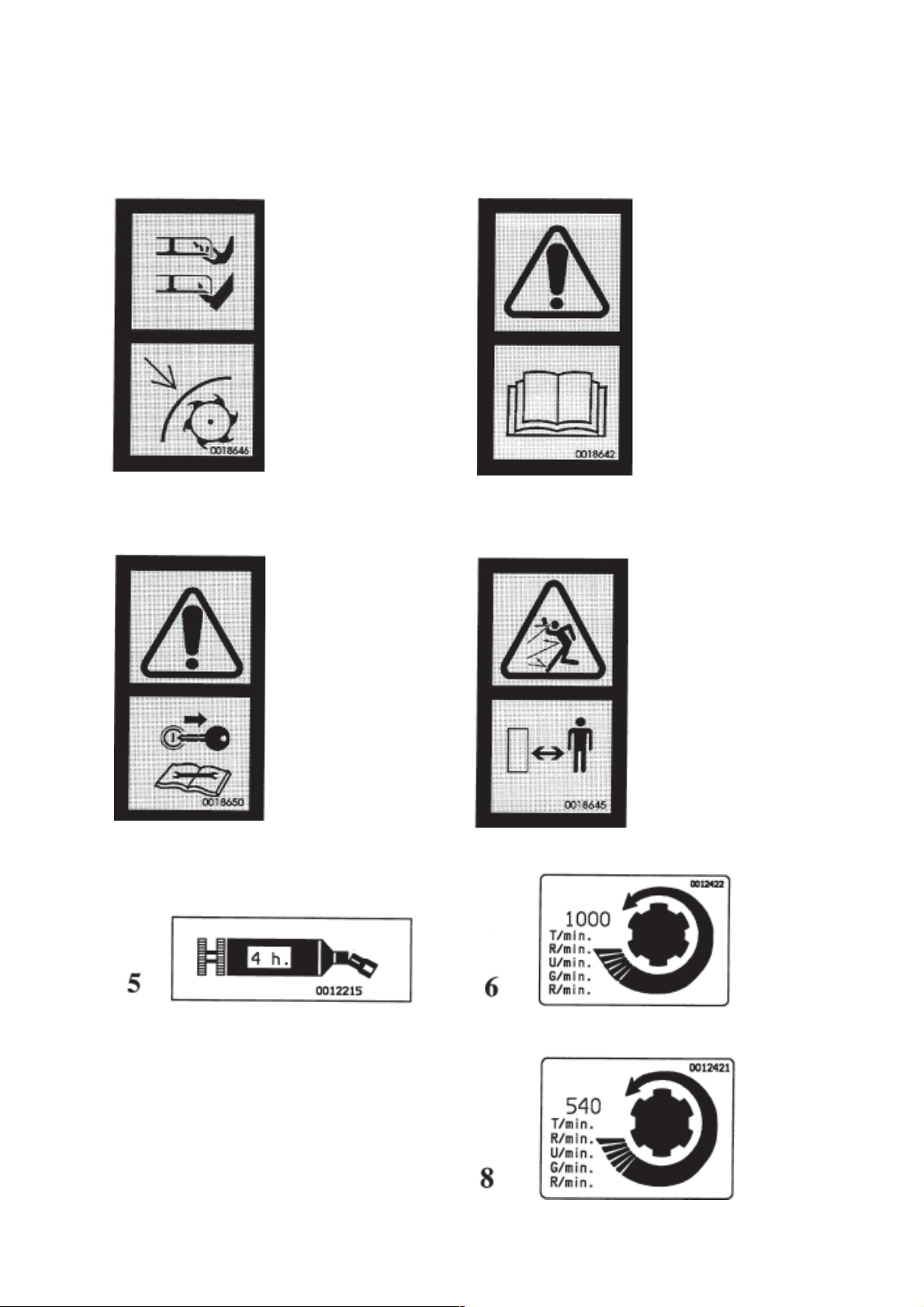
Wait until all moving
parts have come to a
complete stop before
getting in contact with
safety devices.
Before starting the
machine, read operator's
manual and safety
instructions.
12
3
Before adjusting,
maintaining or repairing
the machine, turn off the
engine, remove ignition
key and wait until all
moving parts have come
to a complete stop.
4
Rotating tools !
Objects and debris can be
thrown a long distance.
Keep a safe distance from
the machine.
- 8 -
Page 11
CB - White reflectors at the front
CR - Red reflectors at the rear
- 9 -
Page 12

The shredders WMU are universal shredders designed for maintenance of set-aside, pasture-land or grassed-areas.
They are fitted with a mechanical offsetting parallelogram (hydraulic as option) and forged scoop hammer knives
which ensure fine shredding of nearly all material of medium density. The rear cover opening is adjustable in three
positions.
For shredding vine branches and tree prunings the rear cover must be replaced by a beam which carries a number
of collecting rake tines. This is available as an option for the WMU 230, and ensures that residues on the soil surface
are lifted to avoid direct soil/hammer knife contact.
TECHNICAL SPECIFICATIONS
TECHNICAL SPECIFICATIONS WMU 210 WMU 230 WMU 265 WMU 305
Tractor mounting 3 point, Cat. 2
PTO speed (rpm) 540 540 540 540 or 1000
Mini PTO power requirement kW (hp) 40 (54) 42 (57) 49 (67) 57 (78)
Maxi tractor power kW (hp) 51 (70) 55 (75) 62 (85) 96 (130) *
Overall width (mm/inch) 2304 / 7' 7" 2492 / 8' 2" 2870 / 9' 5" 3244 / 10' 6"
Overall length
(with closed hood) (mm/inch) 1020 / 3' 4" 1020 / 3' 4" 1020 / 3' 4" 1020 / 3' 4"
Weight incl. PTO shaft (kg/lbs) 630 / 1386 lbs 680 / 1496 lbs 755 / 1661 lbs 861 / 1894 lbs
Working position Central, offset possible 580 mm / 1' 10" to the right
Number of hammer knives 22 24 28 32
Working width (mm/inch) 2094 / 6' 10" 2282 / 7' 6" 2660 / 8' 9" 3034 / 10'
Rotor speed
- 540 rpm rpm (m/s) 1974 (48) 1974 (48) 1974 (48) 1833 (44)
- 1000 rpm rpm (m/s) - - - 1960 (48)
Central gearbox oil bath, with integrated free-wheel
Side transmission belts (SPBX)
Height adjustment manual
Rear cover Adjust. to 3 positions, discharging behind the roller
Optional accessories :
- Collecting rake yes yes no no
- Hydraulic parallelogram offsetting
with integrated lock valve yes yes yes yes
* with P.T.O. speed of 1000 rpm.
- 10 -
Page 13

MACHINE LOADING/UNLOADING INSTRUCTIONS
Unload the machine using an appropriate lifting device fitted with a hook (hoist, crane etc.) whose minimum capacity
is 1000 kg.
Machine weight with standard equipment : WMU 210 = 630 kg (1386 lbs)
WMU 230 = 680 kg (1496 lbs)
WMU 265 = 755 kg (1661 lbs)
WMU 305 = 861 kg (1894 lbs)
Lifting device should be attached to the lower anchorage holes (Ø 30 mm) on the machines side plates and to the
top link pin.
When the machine is being manoeuvred the wheels should be blocked in the transport position. Cables and hooks,
in good condition and suitable for the machines weight should be used.
Check the load is distributed evenly before manoeuvring.
- 11 -
Page 14

FITTING INSTRUCTIONS AND ADJUSTMENTS
1) Fitting instructions for the wheels or the roller
Gauge roller version :
The rear hood (A) can only be fitted in association with
the roller. To fit it, insert it between the side plates then
fix it using the 4 nuts and bolts (F).
The roller support (D) is fitted onto 2 side arms through
2 housings. Fix the arms of the roller using the holes
(G) or (G) designed for this on the side plates.
Slide the upper fixation brackets onto the side plates
sheath and insert the pin at the required working height (for setting the working height see pages 13 and 14).
Gauge wheel version :
The gauge roller version, being the most commonly used, requires you to dismantle the rear hood and the roller
beforehand.
- The rear crosspiece (CD) is to be fixed on the rear hood location with 4 nuts and bolts, in the holes drilled at this
end of the side plates.
- Fit the yokes (P) to the inside of the rear crosspiece (CD).
- Bolt the wheel supports (R) onto the yokes (P) with the self locking nuts
- Insert the fixation pins into the wheel arms (BR)
- Bolt the side protections (PP) onto the plates.
- 12 -
Page 15

2) Adjusting the wheel track (gauge wheel)
The wheel supports can be slid onto the rear beam making sure that the machines wheels are not positioned in
line with those of the tractor (creation of ruts by the tractor wheels in damp conditions changes the regularity of the
working height).
3) Adjustment of working height
The hammer knives must not touch
the ground. The minimum working
height must not be lower than 25 mm.
Gauge roller version :
- Slightly raise the machine with the tractor 3-point lift
so that the rear roller is still in contact with the
ground.
- Remove the R-clip (C).
- Release screw (V).
- Lift the large side slider (S).
- Carry out the same procedure on the other side of the
machine (small deflector fitted under the belt guard).
- Remove the pin (P).
- If pin (P) will not come out easily it is likely that the
machine has been lifted too high behind the tractor.
- 13 -
Page 16

- When the roller has been placed in the correct
position to give the desired working height, replace
the pin (P) in its corresponding position.
- Retighten screw (V).
Note : When the pin is placed in the lower hole, the
ground/machine distance (i.e. shredding height)
is greatest.
Roller position with respect to the rotor
Choose the hole (A) or (B) for the side roller mounting
arms to ensure that the roller is as close as possible
to the hammer knives.
When adjusting the machine to shred close to the ground, fix the side roller mounting arms
in holes (B) to avoid any risk of contact between the hammer knives and the roller.
- Replace the larger slider and lock it in position using
R-clip (C).
Adjustment of the rear cover
The opening/closing of the rear cover (A) is adjustable
in 3 positions. To adjust, remove the bolt (F) and pivot
the cover until the required fixing hole (P) is in line with
the hole in the side-plate. Replace the bolt (F) with its
washer, and tighten the nut.
- 14 -
Page 17

Gauge wheel version :
- Raise the machine above the ground.
- Fix the parking stand in place.
- Place the wheel arms at the required height using
the fixation holes (E and F) on the wheel arms.
Position 1 : for a working height range between 25
and 50 mm.
Position 2 : for a working height range between 50
and 150 mm.
Never reverse when the wheels are resting on the ground.
- 15 -
Page 18

UNCOUPLING THE MACHINE
Only uncouple the machine on a level firm surface.
Stop the tractor motor.
Take out the ignition key.
Wait until the moving parts have come to a complete stop.
- Lower the hydraulic lift so that the machine is resting on the ground.
- Uncouple the top link on the machine side.
- Rest the PTO transmission shaft in the support (G) to avoid it touching the ground and being dirtied.
- Fix the stand (P) in place using pin (F) and spring cotter pin (S)
- Disconnect the lower link arms and move the tractor away.
- When setting down on the outside, check that the front part of the machine is slightly tilting downwards so that
the water can drain away.
- 16 -
Page 19

ADAPTING TO THE TRACTOR
In the area around the 3-point hitch an operator or bystander can easily be pinched or
trapped.
Ensure that there is nobody in this area when operating the lifting mechanism.
- WMU shredders can be offset to the side : place the machine in the required offset position (see page 18).
- Fix the hitch pins (D) in place as well as the lynch
pins (S) :
. in the oblong holes (A) : mobile position
. in the round holes (F) : fixed position
- Top link : It is essential to use the pivoting connection made up of the 2 brackets (M) fixed on the
machines attachment frame. A good setting is an
angle of 45° downwards compared to the frames
axis (see drawing).
- Connect up the PTO shaft. Prevent the protector from
rotating using the chains designed for this.
- Raise the parking stand and lock it using pin (F)
and spring cotter pin (S) (see figure on page 16).
Important :
Machine is correctly attached when horizontal in the
working position. To do this, adjust the top link (P)
length.
During transport, lock the tractor lift arms in order to avoid any side movement.
- 17 -
Page 20

MACHINE OFFSETTING
Offsetting by hydraulic parallelogram must only be carried out with the machine in raised
position, and the roller or the wheels clear of the ground.
Offsetting by mechanical parallelogram:
With the machine raised, remove the locking pin from the slider and move the machine sideways in the required
position. Adjust the turnbuckle to the correct position and replace the locking pin. Do not forget to replace the clip.
Offsetting by hydraulic parallelogram (optional extra) :
The offsetting is adjusted by means of a double-acting hydraulic cylinder connected to the tractor hydraulic outlets.
A lock valve integrated into the circuit avoids any accidental movement of the machine.
- 18 -
Page 21

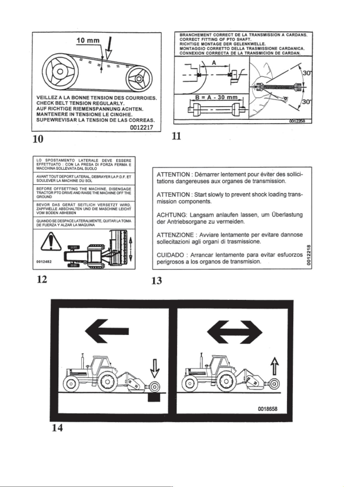
PTO TRANSMISSION SHAFT
Connect the PTO shaft between the drive shaft of the machine and the tractor PTO.
Ensure that the length of the PTO shaft is correct:
1° When extended to maximum ensure at least 300 mm / 12" tube overlap.
2° When in its shortest position, the tubes must not contact the opposite fitting. At least 2 cm / 1" must remain
between the end of the tube and the opposite fitting. If required, cut the guards and tubes by the same length
(fig. 1 & 2), chamfer and clean the tubes (fig. 3), and grease the inside of the outer tube (fig. 4).
3° Never work the PTO shaft at too sharp an angle (30° maximum).
We advise strongly that these preliminary adjustments be carried out, to avoid damage to the
transmission.
To avoid risk of serious accident, check carefully that the transmission guards are always
correctly in place, and prevented from rotating by the chains. On the machine side, the chain
should be fixed to the guard cone on the central gearbox. Replace immediately any
damaged guard.
- 19 -
Page 22

ROTOR SPEED
The WMU 210 - 230 - 265 are designed to be used with tractors with a PTO speed of 540 rpm.
On WMU 305, the correct rotor rotating speed can be obtained at 540 or 1000 PTO rpm.
When the tractor has a PTO speed of 1000 rpm, it is advised to use it in order to obtain the maximum power
generation.
Using the machine at 540 or 1000 rpm is determined according to the position of the pulleys.
Stop the tractor motor. Take out the ignition key. Wait until all moving parts have come to
a complete stop.
Position of pulleys
(P.T.O. 540 rpm)
Position of pulleys after having
switched round (P.T.O. 1000 rpm)
Locking bolt torque on pulley : 2.5 daNm / 20 ft.lbs.
After reassembling the pulleys, check the parallelism between the rotor axis and the transmission axis
(see chapter tensioning the belts page 23).
Never work in stony or rocky grounds.
- 20 -
Page 23

OPTIONAL ACCESSORIES
1) Collecting rake
1.1. For machines in operation fitted with a gauge roller
kit (fixation beam + collecting rake tines.)
WMU 210 ref. 155 6342
WMU 230 ref. 155 6234
1.2. For machines in operation fitted with gauge wheels
(collecting rake tines only).
WMU 210 ref. 155 6346
WMU 230 ref. 155 6056
Note : The fixation beam serves as a support for the gauge wheels and the collecting rake tines.
2) Rear gauge wheels
2.2. For machines in operation and not fitted with a collecting rake (fixation beam + pair of wheels)
WMU 210 Ref. 155 6344
WMU 230 Ref. 155 6315
WMU 265 Ref. 155 6330
WMU 305 Ref. 155 6339
2.2. For machines in operation fitted with a collecting rake (pair of wheels only)
WMU 210 / WMU 230 Ref. 155 6350
WMU 265 / WMU 305 Ref. 155 6351
3) Hydraulic parallelogram offsetting
Ref. 155 6242
The offsetting of the machine may only be done when the machine is raised (roller or wheels are off the ground). The
offsetting is done by a double acting hydraulic cylinder connected to the tractors hydraulic circuit. An lock valve
in the cylinder avoids any accidental modifications to the machines position.
- 21 -
Page 24

MAINTENANCE
BEFORE CARRYING OUT ANY OPERATION SUCH AS MAINTENANCE OR ADJUSTMENT
ON THE MACHINE, STOP THE TRACTOR ENGINE, REMOVE IGNITION KEY AND WAIT
FOR ALL MOVEMENTS TO STOP.
1) Lubrication
- PTO shaft (G): every 8 hours of use, clean and grease the universal joints and the shaft tubes.
- Central gearbox (Z): first oil change after 10 hours of use, then every 250 hours or once per season. Oil type: SAE
90EP (ISO 220).Quantity: 1.5 litre. Regularly check the oil level (see following page).
- Every 50 hours, grease the parallelogram pivot points (I) with a lithium based grease. The pivot pins for the
parallelogram are fitted with special bushes. The bushes should be replaced as soon as the pins have excessive
play.
- Every 8 hours, grease the rotor bearings (R) and the roller bearings (S) with a Lithium compound.
- If necessary, oil all the pivot points with SAE 90EP oil.
TO ENSURE TROUBLE FREE OPERATION OF YOUR MACHINE,
WE RECOMMEND SHELL LUBRICANTS.
- 22 -
Page 25

2° Belt Tension
Check belt tension regularly especially during the first hours of use.
The belt tension can be measured using a ruler scale (R ) placed through the hole in the hood.
Checking the belt tension
- Stop the tractor engine, remove ignition key and wait for all moving parts to stop before leaving the tractor
- Loosen screws (A) and (B) which fix the central casing to the frame of the machine.
- Loosen adjustment screw lock-nuts (C) and (D)
- Turn the screw (F) clockwise until the belts are correctly tightened. The belt is correctly tightened when a force
of 20 kilo gives a belt deflection of 10 mm/0.4" (see transfer)
- Adjust adjustment screw (G) by the same amount so that the central transmission shaft (PR) is parallel to the
machine rotor
- Retighten screws (A) and (B) as well as lock-nuts (C) and (D).
Checking the parallelism between the rotor axis and transmission shaft
Before adjusting, maintaining or repairing the machine, turn off the engine, remove ignition
key and wait until all moving parts have come to a complete stop.
- Remove the belt guard
- Place a ruler against the sides of the rotor pulley
- Slide the rotor pulley so that the ruler comes against the sides of the other pulley
- The ruler must be in contact with the 2 sides of the two pulleys. If not, screws (F) and (G) should be adjusted again
as well as the lock-nuts (C) and (D)
- Remount the belt guard.
- 23 -
Page 26

HAMMER KNIVES FITTING
Periodically check the condition and fixing of the hammer knives. Replace immediately any worn or damaged parts
with genuine KUHN parts.
BEFORE CARRYING OUT THIS WORK, ALWAYS DISCONNECT THE PTO SHAFT.
USE ONLY GENUINE PARTS.
- Remove all hammer knives.
- Weigh all the hammer knives individually and put all the knives which have the same weight together.
- Fit all pairs of hammer knives with the same weight on diametrically opposite mountings.
- Place the heaviest pairs to the outside of the rotor, and the lightest pairs towards the centre.
- When changing a hammer knife, tighten the M 16 locknut to a torque of 10 daNm / 75 ft.lbs. After tightening the
nut, there should still be a sideways play of 1 to 2 mm.
- After fitting the hammer knives, couple the machine to a tractor. Raise it slightly and gradually increase the PTO
speed until it is at 540 or at 1000 rpm (see chapter "Rotor speed" page 20).
- When the hammer knives are correctly fitted, there should be no vibration while the rotor is running.
- Check that the hammer knives are correctly fitted ! (A = forward direction).
- 24 -
Page 27

- 25 -
Page 28

CHECKING HAMMER KNIFE MOUNTING AXLES WEAR
Hammer knives must be checked each time before using the machine. They must systematically be checked after any impact to the machine.
Shredding quality, reliability of the machine and your safety depend on regular checking of these elements.
The hammer knives must be replaced in the following cases :
Damaged hammer knives :
Any impact to the machine can cause the hammer knives to warp or crack with the following consequences :
- Reduction in shredding quality
- Increase in vibrations bringing with it mechanical problems on the machine
- Partial or total breakage of the hammer knives with risk of projections.
Worn hammer knives (fig. A) :
- The fixation hole diameter (F) should not be oval-shaped by more than 2 mm in relation to its original diameter.
- The length (L) of the hammer knife should not be less than 30 mm in comparison to its original length.
The mounting axle should be changed if (fig. B) :
- The thread is damaged. Also check the weld at the head of the fixation screw (S)
- The axle is worn down by more than 2 mm (H).
The self-locking nuts cannot be used more than twice.
Check the washers regularly.
Torque of M 16 nuts : 10 daNm / 75 ft.lbs.
- 26 -
Page 29

Initial
hole 16
diameter (F)
Maximum
diameter 18
allowed (F')
Initial
length 110
of knive (L)
Minimum
accepted 90
length (L')
- 27 -
Page 30

OPERATING ADVICE
- Always stop the tractor engine before carrying out any adjustments or maintenance on the machine.
- Do not start the rotor turning unless the machine is slightly raised. Do not lower the machine into its working
position until it has reached its correct working speed.
- Never work around corners. Always lift the machine before turning corners.
- Stop the PTO shaft when the lifted position of the machine gives a PTO shaft angle of more than 30°.
- The hammer knives must never contact the ground.
- Check daily the blade wear.
- Replace immediately any irregularly worn or damaged parts. Use only genuine KUHN parts.
- Check daily that all nuts and bolts are correctly tightened. Check especially the tightening torque of the hammer
knife fixing bolts (10 daNm / 75 ft.lbs).
- Check that the safety chains and flexible safety links on the transmission guards are correctly attached and are
in good condition.
- Clean and lubricate regularly the interior and exterior of the machine. Any soil that has built up on the rotor and
rotor bearings must be removed.
- Carefully clean and lubricate the machine before storing it. Store the machine always under cover.
- The user is responsible for the machine when it is transported on any public highway. It is important to respect
the Highway Code.
- If unusual vibrations are felt during work, stop the machine immediately and check the rotor. The vibrations may
be caused by the hammer knives. If the machine is used in this condition, it could be seriously damaged.
Before starting up the machine and beginning work, keep all people and animals away from
the danger zone of the machine (risk of projection !)
The manufacturer cannot be held responsible for any damage caused by incorrect use of the
machine or if the user has not followed the instructions given in this manual.
- 28 -
Page 31

TROUBLE SHOOTING GUIDE
PROBLEM POSSIBLE CAUSE REMEDY
Excessive A) Hammer knives damaged or Replace the hammer knives
vibration excessively worn (pages 25 - 26)
B) Hammer knives not free to rotate Clean and lubricate
C) Balancing problem Check the weight of each row of
hammer knives (page 25 - 26)
D) Rotor bearing wear Replace the rotor bearings
Shredding quality A) Incorrect belt tension Retighten belts
not satisfactory (page 23)
due to reduction
of rotor speed B) Excessive belt wear Replace belts and check
parallelism between the rotor axis
and transmission shaft
Belt heating A) Incorrect belt tension Retighten belts
(page 23)
B) Central transmission and rotor Check the setting
are not parallel (page 23)
Central gearbox A) Insufficient oil quantity, oil needs Check oil level, check if
heating replacing or incorrect oil quality oil change due
(page 22)
Excessive wear A) Working height too low Adjust the working height
of hammer knives (pages 13 to 15)
Oil leak Oil seal worn or damaged Replace oil seal and check
pressure relief valve for good
function
- 29 -
Page 32

SOUND LEVELS
Sound levels given out by : WMU 210 - WMU 230 - WMU 265 - WMU 305 Shredders
Sound levels have been measured in accordance with the measuring methods as defined in :
HM Agricultural Inspectorate
AGRICULTURAL MACHINERY NOISE
Legislation and guidance on methods of testing
(Annex to AIC 1896/117 REV)
February 1988
Health and Safety Executive
The method employed corresponds to the method No. 4 in this document. Unspecified testing
conditions comply with ISO 5131 standard.
Measuring equipment conforms to NF S 31-009 standard. The tractor used has a power of 58 kW.
A-weighted emission sound pressure level L (A) eq inside tractor cab (with closed windows) :
Tractor only : 78.8 dB(A)
Tractor + machine : 79.1 db(A)
- 30 -
Page 33

LIMITED WARRANTY
KUHN S.A. of 4 Impasse des Fabriques, 67706 SAVERNE CEDEX, France (hereinafter called the
«Company») warrants, in accordance with the provisions below, to each original retail purchaser of
KUHN new equipment of its own manufacture, from an authorized KUHN dealer, that such equipment
is, at the time of delivery to such purchaser, free from defects in material and workmanship and that
such equipment will be warranted for a period of one year starting from the date the goods are delivered
to the end user and during this period up to a limit of 500 hours use, providing the machine is used and
serviced in accordance with the recommendations in the Operators Manual.
THESE CONDITIONS ARE SUBJECT TO THE FOLLOWING EXCEPTIONS :
1. Parts of machines which are not of our manufacture i.e. tyres, belts, P.T.O. shafts, clutches etc., are not
covered by this Limited Warranty but are subject to the warranty of the original manufacturer. Any claim
falling into this category will be taken up with the manufacturer concerned.
2. Warranty claims applying to these types of parts must be handled in the same way as if they were parts
manufactured by KUHN. However, compensation will be paid in accordance with the warranty agreement of the manufacturer concerned in as much as the latter justifies such a claim.
3. This Limited Warranty will be withdrawn if any equipment has been used for purposes other than for
which it was intended or if it has been misused, neglected or damaged by accident or let out on hire. Nor
can claims be accepted if parts other than those manufactured by us have been incorporated in any of
our equipment. Furthermore, the Company shall not be responsible for damage in transit or handling by
any common carrier and under no circumstances within or without the warranty period will the Company
be liable for damages for loss of use or damages resulting from delay or any consequential damage.
We cannot be held responsible for loss of earnings caused by a breakdown or for injuries either to the owner
or to a third party, nor can we be called upon to be responsible for labor charges, other than originally
agreed, incurred in the removal or replacements of components.
THE CUSTOMER WILL BE RESPONSIBLE FOR AND BEAR THE COSTS OF:
1. Normal maintenance such as greasing, maintenance of oil levels, minor adjustments, etc.
2. Transportation of any kind of any KUHN product to and from the place the warranty work is performed.
3. Dealer travel time to and from the machine or to deliver and return the machine from the workshop for
repair.
4. Dealer travelling costs.
Parts defined as normal wearing items are listed as follows and are not in any way covered under this
Limited Warranty :
V belts, discs, knives, wear plates, disc guards, tires, torque limiters, hydraulic hoses, pitman shafts, swath
sticks, blades, tines and tine holders.
KUHN Limited Warranty will not apply to any product which is altered or modified without the expressed
permission of the Company and/or repaired by anyone other than Authorized Service Distributors or
Authorized Service Dealers.
Page 34

LIMITED WARRANTY IS DEPENDENT UPON THE STRICT OBSERVANCE BY THE
PURCHASER OF THE FOLLOWING PROVISIONS :
- That this Limited Warranty shall not be assigned or transferred to anyone unless the Companys consent in
writing has first been obtained.
- The warranty/product registration form has been correctly completed by dealer and purchaser with their
names and addresses, dated, signed and returned to the appropriate address as given on the warranty/
product registration form.
- The claim form sent to KUHN has been correctly completed stating:
* dealers name and address
* owners name and address
* type of machine
* machine serial number
* delivery date to buyer
* date of failure
* tractor make and type
* description of the failure and its cause
* quantity, reference number and name of the damaged parts
* reference number, quantity and date of the invoice for the replacement parts.
- The judgement of the Company in all cases of claims under this Limited Warranty shall be final and conclusive and the purchaser agrees to accept its decisions on all questions as to defect and to the exchange of
any part or parts.
- That all safety instructions in the Operators Manual shall be followed and all safety guards regularly inspected
and replaced where necessary.
No warranty is given on second-hand products and none is to be implied. Persons dealing in the Companys
products are in no way legal agents of the Company and have no right or authority to assume any obligation
on their behalf, express implied, or to bind them in any way.
KUHN S.A. reserves the right to incorporate any change in design in its products without obligation to make
such changes on units previously manufactured.
Moreover, because of the constant progress in technology, no guarantee is given to the descriptions of
equipment published in any document by the company.
DISCLAIMER OF FURTHER WARRANTY
There are no warranties, expressed or implied, except as set forth above. There is no
warranty of merchantability. There are no warranties which extend beyond the description
of the product contained herein. In no event shall the company be liable for indirect, special
or consequential damages (such as loss of anticipated profits) in connection with the retail
purchasers use of the product.
Page 35

This machine complies with the safety requirements of the European machinery directive.
The Operator should respect all Health and Safety regulations as well as the Highway
Code. For your own safety, use only genuine KUHN spare parts. The manufacturer
disclaims all responsibilities due to incorrect use or non-compliance with the
recommendations given in this manual.
Page 36

For your safety
and to get the best from your machine,
use only genuine KUHN parts
KUHN S.A. 4 Impasse des Fabriques F - 67706 SAVERNE CEDEX (FRANCE)
Tél. : + 33 (0) 3 88 01 81 00 - Fax : + 33 (0) 3 88 01 81 03
www.kuhnsa.com - E-mail : info@kuhnsa.com
Société Anonyme au Capital de 19 488 000 Euros
Printed in France by KUHN
 Loading...