

Page 1
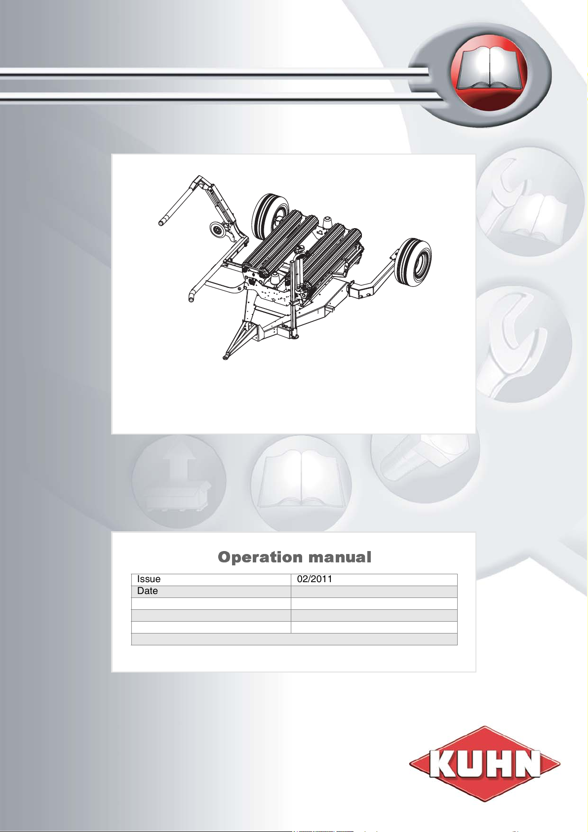
SW1604
Operation manual
Issue 02/2011
Date of printing 2.2011
Language EN
From machine number (PIN) VGTW000001 ->
Reference number ZNA066EN
Original instructions
Page 2

Identification of the machine
To support you as soon as possible your dealer requires several details of your machine.
Please enter the information here.
Designation
PIN
Software version
Assembled
options
Address of
the dealer
SW1604
VGTW..........
Address of the
manufacturer
KUHN-GELDROP B.V.
Nuenenseweg 165
NL-5667 KP Geldrop
The Netherlands
Phone +31 40 2893300
KUHN is continually striving to improve its products and, therefore, reserves the right to make improvements or changes when it becomes practical
to do so, without incurring any obligations to make changes or additions to the equipment sold before.
Copyright 2011 KUHN-GELDROP B.V.
Page 3

BG
ÀɤȠ ɬȠɜa pɔƸȠɜȠȾcɬɜȠ e ɩoɥyɱɟɧɨ ɧɚ ɟɡɢɤ, ɤɨɣɬɨ ɧɟ ɦɨԓɟ ɞɚ ɛɴɞɟ ɪɚɡɛɪɚɧ ɨɬ ɨɩɟɪɚɬɨɪɚ ɧɚ
ɦɚɲɢɧɚɬɚ, ɫɜɴɪԓɟɬɟ ɫɟ ɫ ɜɚɲɢɹ ɞɢɥɴɪ.
CS
Pokud obdr_íte tento návod v jazyce, kterému pracovník obsluhy stroje nerozumí, spojte se s
Vašim prodejcem.
DA
Hvis du har modtaget manualen på et sprog, som operatøren af maskinen ikke forstår, skal du
kontakte forhandleren.
DE
Sollten Sie diese Betriebsanleitung in einer Sprache erhalten haben, die der Bediener dieser
Maschine nicht versteht, kontaktieren Sie bitte Ihren Händler.
EL
EȐv ĮȣIJȩ IJo EȖȤİȚȡȓįȚȠ OįȘȖȚȫv XȡȒıȘȢ, İȓvĮȚ ıİ ȖȜȫııĮ ʌȠȣ įİv ȝʌoȡİȓ vĮ
įȚĮȕĮıIJİȓ Įʌȩ
IJov ȤİȚȡıIJȒ IJoȣ ȝȘȤĮvȒȝĮIJoȢ, ʌĮȡĮțĮȜȠȪȝİ vĮĮʌİȣșȣvșİȚIJİ ıIJov IJoʌȚțȩ ıĮȢ ĮvIJȚʌȡȩıȦʌo.
EN
If this manual is received in a language which cannot be understood by the operator of the
machine, contact your dealer.
ES Si recibe este manual en un idioma que no pueda ser entendido por el usuario de la máquina,
póngase en contacto con su proveedor.
ET
Kui käesolev juhend saadakse keeles, millest masinajuht ei saa aru, siis pöörduge edasimüüja
poole
FI
Jos käyttöohjeen kieli on sellainen, jota koneenkäyttäjä ei ymmärrä, on otettava yhteys
jälleenmyyjään
FR
Si vous recevez ce manuel dans une langue que l’opérateur de la machine ne comprend pas,
veuillez contacter votre concessionnaire.
GA
Má fhaightear an lámhleabhar seo i dteanga nach dtuigeann oibreoir an mheaisín, téigh i
dteagmháil le do cheannaí.
HR
Ako je ovaj priruþnik dostavljen na jeziku koji rukovatelj stroja ne razumije, kontaktirajte Vašeg
prodavaþa.
HU
Ha ez a gépkönyv olyan nyelven készült, amelyet a gép kezelĘ
je nem ért, vegye fel a kapcsolatot
a forgalmazóval
IS
Ef handbókin er á tungumáli sem notandinn skilur ekki, skal hafa samband við söluaðila.
IT
Se l’utente della macchina riceve il presente manuale in una lingua che non comprende,
suggeriamo di contattare il rivenditore.
Page 4

LT
Jei šƳ vadovą gavote kalba, kurios mašinos operatorius nesupranta, kreipkitơs Ƴ platintoją.
LV
Ja saĖemtâ rokasgrâmata ir maÿînas operatoram nesaprotamâ valodâ, sazinieties ar tirgotâju.
MT
Jekk dan il-manwal jiƥi rƛevut f’lingwa li ma tkunx tista’ tinftiehem mill-operatur tal-magna,
ikkuntattja lill-aƥent tiegƫek
NL
Als u deze handleiding heeft ontvangen in een taal die voor de bediener van de machine niet
begrijpelijk is, raadpleeg uw dealer.
NO
Kontakt forhandleren hvis denne bruksanvisningen er på et språk som maskinoperatøren ikke
forstår.
PT
Se este manual for recebido num idioma que não seja entendido pelo operador da alfaia,
contacte o seu concessionário.
PL Ja saĖemtâ rokasgrâmata ir maÿînas operatoram nesaprotamâ valodâ, sazinieties ar tirgotâju.
RO Dacă prezentul manual este primit într-o limbă care nu poate fi înĠeleasă de către operatorul
maúinii, contactaĠi distribuitorul dumneavoastră.
RU
ȿɟɥɢ ɨɩɟɪɚɬɨɪ ɩɨɥɭɱɢɥ ɪɭɤɨɜɨɞɟɫɬɜɨ ɧɚ ɹɡɵɤɟ, ɤɨɬɨɪɵɣ ɨɧ ɧɟ ɩɨɧɢɦɚɟɬ, ɧɟɨɛɯɨɞɢɦɨ
ɨɛɪɚɬɢɬɖɫɹ ɤ ɞɢɥɟɪɭ.
SK
Ak dostanete túto príruþku v jazyku, ktorému operátor stroja nerozumie, spojte sa so svojím
predajcom.
SL
ýe ta priroþnik prejmete v jeziku, ki ga upravljavec stroja ne razume, se obrnite na svojega
trgovca.
SV
Kontakta återförsäljaren om denna manual tagits emot på ett språk, som inte förstås av
maskinoperatören.
Page 5

Table of contents
Preface .............................................................7
Target group of this operation manual 7
Training 7
Symbols used 8
Safety instructions .........................................9
For your safety 9
Safety decals 10
Who is allowed to operate the machine? 13
General 13
Hitching the machine 15
Hydraulics 16
Road transport 17
Operation 19
Unhitching the machine 21
Maintenance 22
Further prescriptions 23
Warranty and responsibility 23
Familiarize yourself with the machine ........ 24
General 24
Product description 24
Main components overview 25
Technical specifications 26
Control systems 29
Delivery and assembly .................................32
Check the scope of delivery 32
Hitching the machine ...................................33
Safety 33
General 33
Checklist 33
Hitching 34
Mechanical connections 35
Electronic connections 36
Hydraulic connections 37
Preparation for use .......................................39
Safety 39
Preparations 39
Support rollers adjustment 41
Pre-stretcher adjustment 42
Film installation 43
Loading arm disc adjustment 44
Loading arm adjustment 44
Checklist 44
Table of contents
Road transport .............................................. 45
Safety 45
General conditions 46
Empty the wrapping table 46
Wrapping table horizontal 47
Wrapping table in transport
position 47
Loading arm in transport position 48
Adjustable wheels in transport position 49
Hydraulic adjustable wheels[+] in
transport position 50
Checklist 50
Preparations at the field .............................. 51
Safety 51
Change settings 51
Set into operating mode 51
Wrapping table horizontal 52
Wrapping table in operating position 52
Loading arm in operating position 53
Adjustable wheels in operating position 54
Hydraulic adjustable wheels[+] in
operating position 54
Checklist 55
Operation ...................................................... 56
Safety 56
Required film wraps 57
Start position 58
Loading a bale 58
Wrapping procedure 60
Wrap and bale counter ................................. 63
General 63
Wrap and bale counter box 63
Parameters 64
Parameter settings 64
Electronic control system ...........................66
General 66
Control panel 66
Parameter settings 69
Cleaning and care ........................................ 79
Safety 79
Caution 79
Cleaning 80
Parking and storage ..................................... 81
Safety 81
Unhitching the machine 81
After the season 81
5
Page 6

Table of contents
Maintenance ..................................................82
Safety 82
General 85
Oil and lubricants specifications 85
Maintenance table 86
Complete machine 88
Bolted connections 89
Torques for bolted connections 90
Film wrapper 91
Film cutter 92
Hydraulic components 93
Wrapping table 94
Loading arm 97
Drawbar 98
Axles, wheels and tyres 99
Sensors 102
Sensor overview 103
Diagrams and schemes 104
Optional equipment ....................................105
General 105
Film roll holders 105
Film break set 106
Gear kit pre-stretcher 106
Remote control 106
Wheel chocks 106
Drop mat 107
Counterweights 107
Troubleshooting ........................................108
Safety 108
Error messages 109
Film Cutter 113
Pre-stretcher 114
Loading arm 114
Hydraulics 114
Film Roll 115
Bale 115
Adjustments 116
Disposal of the machine ............................120
Index ............................................................121
EC Declaration of Conformity ................... 123
6
Page 7

Preface
Preface
Target group of
this operation
manu al
Trainin g
This operation manual is directed at trained farmers and individuals
who are otherwise qualified to perform agricultural activities and who
have received instruction to handle the machine.
For your safety
You must familiarize yourself with the contents of this operation
manual before assembly or initial operation of the machine. In this
way, operating and work safety are optimized. The operation manual
is an integral part of the machine and must always be kept to hand.
This will allow:
• Accidents to be avoided.
• The warranty conditions to be met.
• A well-functioning machine in good working order.
Your dealer will give you instruction about operation and care of the
machine.
Employer information
All personnel has to be regularly instructed how to operate the
machine. At least once a year, in accordance with the regulations of
the national organization for Health and Safety at Work. Untrained or
unauthorized individuals are not allowed to use this machine.
You are personally responsible for the safe operation and
maintenance of the machine. Always ensure that all personnel who
operate or maintain the machine are familiar with the operation and
maintenance instructions and the relevant safety instructions given in
this operation manual .
7
Page 8

Preface
Symbols used
In this operation manual the following symbols and terms are used:
• A dot accompanies each item in a list.
> A triangle indicates operating functions which have to be
performed.
An arrow indicates a cross-reference to another section of this
manual.
[+] A plus sign indicates an accessory, which is not included in the
standard version.
Next to these symbols, pictographs are used to help you locate other
sections of this manual.
N
OTE
The term “Note“ indicates tips and notes on operation.
The warning triangle indicates important safety instructions. Failure to
observe these safety instructions can result in:
• Serious faults in the correct operation of the machine.
• Damage to the machine.
• Personal injury or accidents.
0
The wrench indicates tips during assemby or adjustments.
A star indicates examples that assist comprehension of the
instructions.
8
Page 9

Safety instructions
Safety instructions
For your safety
This chapter contains general safety instructions. Each chapter of the
operation manual contains additional specific safety instructions
which are not described in this chapter. Observe the safety
instructions:
• In the importance of your own safety.
• In the importance of the safety of others.
• To ensure the safety of the machine.
Numerous risks can result from incorrect handling of agricultural
machines. Therefore, always work with special care and never under
pressure.
Employer information
At regular intervals, inform those who work with the machine about
these safety instructions and the statutory regulations.
9
Page 10
Safety instructions
TR2021
TR1604
TR2021
TR2055TR2014
TR1604
TR1596
TR1612
TR1604
TR1608
TR1586
TR1608
TR1600
TR1610
TR1602
TR1612
TR2055
TR1614
TR1612
TR1612
TR1606
TR1614
TR1608
TR 1586
TR 1600
TR1606
TR 1602
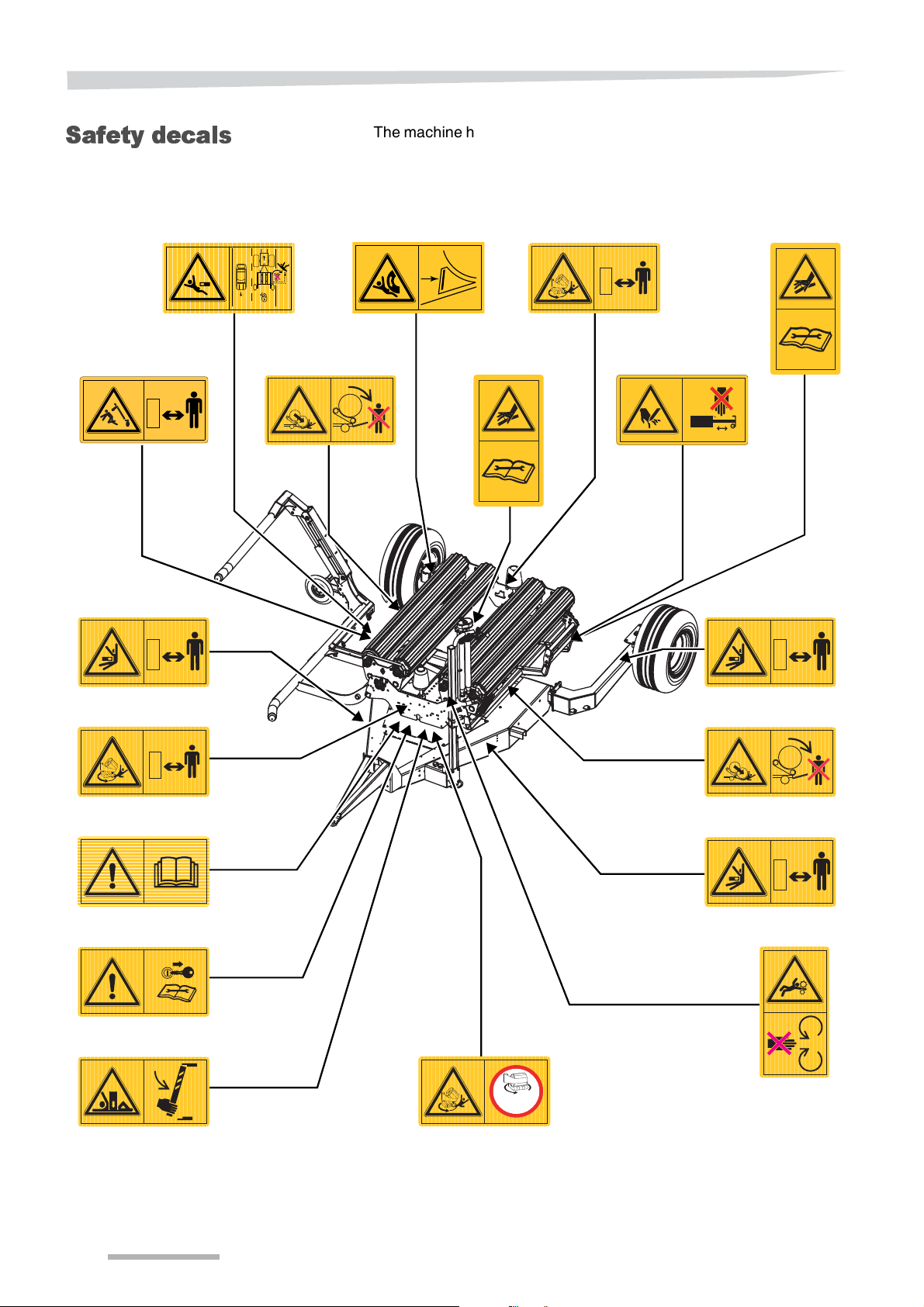
Safety decals
The machine has safety decals for indicating attention to dangers. The
labels may not be removed. Keep all safety decals clean and legible.
In case safety decals are damaged, perished or lost, order new decals
as spare parts and affix them on the machine.
TR1608
TR 1596
TR 2055
TR1604
TR2014
TR 2055
Max
30
TR1612
TR1612
/
min
TR1610
10
Page 11
Safety instructions
TR1606
TR1614
TR1604
TR2014
TR1608
TR 1596
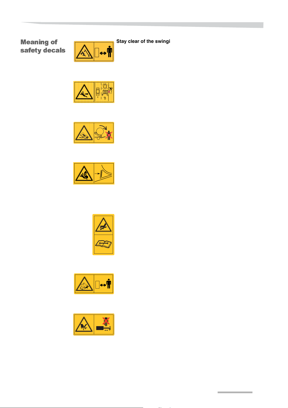
Meaning of
safety decals
Stay clear of the swinging area of the loading arm
Remain a safe distance from the loading arm area. You may get hit by
the loading arm when moving. This could otherwise result in serious
personal injuries.
Apply safety lock before transport
Use the safety lock to secure the loading arm before transporting the
machine on public roads. A lowered loading arm may hit or grab other
road users. Fatal injuires may occur.
Never stay behind the machine during bale ejection
Stand at a safe distance from the bale ejection. The ejected bale can
roll on under its own weight and the speed of area. A rolling bale may
result in damages and serious or fatal injuries
Use wheel chocks before the machine has to be uncoupled or has
to be parked/stored.
Always use wheel chocks if the machine has to be uncoupled or is
parked/stored, to avoid inadvertently rolling away. A non secured
machine can cause serious or deadly injuries and heavy material
damages.
Hydraulic oil under pressure.
Even when the tractor hydraulics are switched off, there is still a
remaining hydraulic oil pressure. Comply with all safety and
maintanance instruction as described in this manual. Escaping oil can
cause injuries and burns.
TR 2055
Keep a safe distance from the wrapping table.
Always remain a safe distance from a rotating wrapping table. You
may get hit by a runaway bale, with serious or deadly injuries as a
result.
Stay clear of the film cutter area
Stay clear of the film cutter area during operating. Cutting danger,
serious personal injuries can occur.
11
Page 12
Safety instructions
TR1612
TR1610
30
Max
/
min
TR 1602
TR 1600
TR 1586
TR2021
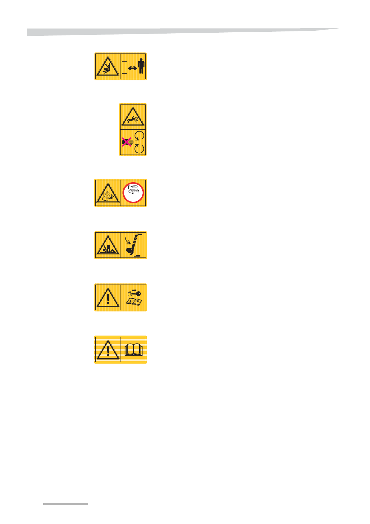
Keep a safe distance from the wrapping table area.
Always keep at a safe distance from the wrapping table area. You may
get hit or squeezed by the machine. Serious or deadly injuries can
occur.
Avoid the pre-stretcher area
Remain a safe distance from the pre-stretcher rollers. Hands and
cloths can be grabbed by the rollers. Serious injuries can occur.
Do not exceed the table rotation speed of 30 rpm.
By exceeding the rotation speed of 30 rpm the bale may come off from
the wrapping table due to extreme high centrifugal forces. A runaway
bale may cause heavy machine damages or fatal personal injuries.
Use the table safety bar
Prior to any maintenance, repairs and adjustmens to a tilted wrapping
table, install the safety bar. A non-secured table can cause serious or
deadly injuries.
Switch off the tractor engine
Carry out all maintenance, repair and adjusting jobs only when the
machine is at a standstill. Switch off electric control systems, hydraulics
and the tractor engine and remove the ignition key. Otherwise serious
or fatal injuries can occur.
Read the operation manual
The machine may only be commissioned once the operation manual
has been read and fully understood. This applies in particular to the
safety instructions.
12
Page 13

Safety instructions
Who i s a llo w e d to
operate the
mach in e?
General
Only qualified personnel
Only qualified personnel who have been informed about the dangers
associated with handling the machine are permitted to operate,
service or repair the machine. This knowledge can be gained by
agricultural training, technical training or intensive instruction.
Safety is your responsibility
Ensure you are always in compliance with the safety regulations. Most
accidents can be avoided by observing the safety instructions.
Use a suitable tractor
Ensure that the tractor meets the listed minimum requirements of the
machine. And ensure that the tractor is capable for safely operating
the machine for all your specific conditions.
»Tractor requirements«, see page 28.
Prescribed workwear
Do not wear loose, baggy clothing to avoid being caught by rotating
parts. Wear workwear and protective clothing as prescribed by the
trade’s mutual indemnity association. Otherwise there is a high risk of
serious or fatal injury.
Oils, lubricants and chemicals
Observe all safety instructions and directions for use for oils,
lubricants and chemicals (like paint, cleaning agents, solvents etc.), as
mentioned on the original packaging or chemical cards.
Fire hazard
Ensure the machine is always clean and remove any remaining crop
to avoid fire hazards.
Fire extinguisher
Equip the machine with a multipurpose ABC fire extinguisher with a
capacity of at least 10 kg. Always use a fire extinguisher which is
approved by the relevant authorities.
Proper operating condition
Ensure that the machine and your tractor are always in a proper
operating condition. Always work with a clean machine, remove any
dirt before operation. Observe the information and technical data in
the operation manual of your tractor.
Running in enclosed space
A machine connected and coupled to the tractor may never be used
in enclosed spaces. Combustion engine exhaust fumes are
dangerous, and may cause asphyxiation.
Never work on a running machine
Never work on the machine while it is running. Objects or personnel
can be caught, drawn in or crushed. Fatal injuries can occur.
13
Page 14

Safety instructions
Do not modify the machine
No modifications whatsoever may be made to the machine.
Unauthorized modifications can impair safety and effect the life time of
the machine. It even renders the manufacturer’s guarantee null and
void and frees the manufacturer from all liability.
Avoid the area to the rear
Remain a safe distance from the rear area. The ejected bale can roll
under its own weight and the ejected speed. A rolling bale can cause
serious or fatal injuries.
Fire hazards when welding
When welding, be careful of any fire or combustion hazards caused by
sprayed metal and sparks. Work away from flammable objects or cover
them. Seal off gaps and chinks. Ensure there is a suitable fire
extinguisher device and check the working premises; check them again
at the end of the welding process.
14
Page 15

Safety instructions
Hitchi ng th e
machine
Increased risk of injury
While hitching the machine to the tractor there is an increased danger
of injury. Therefore always:
• Secure the tractor and the machine from rolling away.
• Switch off all hydraulic systems.
• Switch off all electronic systems.
• Switch off the tractor engine.
• Remove the ignition key.
• Never stay between the tractor and the machine during hitching.
Failure to comply may cause damage to the machine and even life
threatening injuries.
15
Page 16

Safety instructions
Hydraulics
Hydraulic couplings only pressureless
Only connect hydraulic hoses to the tractor if all hydraulic systems are
pressureless. A pressurized hydraulic system can trigger unforeseen
movements at the machine and may cause serious damage or fatal
injuries.
High pressure in the hydraulic system
The hydraulic system is under high pressure. All pipes, hoses,
couplings and connecting passageways have to be checked for leaks
and other damage on a regular basis. Only use suitable tools when
checking for leaks. Repair any damage immediately. Escaping oil can
cause injuries and burns. Seek medical care immediately when
injuries occur.
»Maintenance«, see page 82.
Searching for hydraulic oil leaks
Never search for leaks by touching hydraulic hoses and hydraulic
connections, even when your hands are protected with a protective
skin cream or oil-resistant gloves. Always use a piece of paper when
looking for leaks.
Due to high pressure and very little holes in case of leakages, the
hydraulic oil will go through protection devices and your skin!
Hydraulic oil may come into your bloodstream, which is
lifethreatening!
16
Page 17

Safety instructions
Road transport
Ensure road safety
If you intend to transport the machine on public roads, the machine
and the combination of tractor and machine have to comply to current
Road Traffic Act’s requirements. This to guarantee your own safety
and the safety of other road users.
For example ensure:
• The license plate, road lighting, warning and protective equipment
is properly installed and functioning. Compliance with the
permissible transport dimensions, weights and axle loads.
• Compliance with the speed limits:
- National and local speed limits.
- Speed limits as indicated in the approval of the machine.
- Never exceed the maximum design speed of 25 km/h, in
case there are no speed limits indicated in the approval or
in case there is no approval.
• Compliance with the brake requirements of the tractor-machine
combination.
Failure to meet the Road Traffic Act’s requirements can result in fatal
accidents.
Tyre pressure and tyre condition
Check the tyres at a regular base. Bad tyres and an incorrect tyre
pressure will reduce the tyre lifetime and can lead to unpredictable
driving charasteristics of the machine.
Block all hydraulic valves
To avoid inadvertently activation of machine components, activate all
mechanical and/or hydraulic valve locks at the machine. Also lock the
hydraulic valves at the tractor, or disconnect the hydraulic hoses for
machine operation from the tractor.
Always switch off the electronic systems.
Disconnect the 12V power supply cable from the tractor.
Carrying people and objects on the machine is prohibited
Neither persons nor objects are allowed to be transported at the
machine at any time. Only parts stored in their dedicated storage
locations are alllowed to be transported at the machine. Riding on the
machine is hazardous and strictly prohibited.
17
Page 18

Safety instructions
No bale on the machine
It is not allowed to transport a bale on the machine. Transporting bales
will affect steering, braking capability and driving performance of the
combination. Traffic accidents with serious damage or fatal injuries
can occur.
Altered driving and braking performance
Driving and braking performances will change when the machine is
attached to the tractor. Take the width and weight of the machine into
account, especially when cornering. A driving style that is not adapted
to altered conditions can cause accidents.
Adapted speed
In the event of bad road conditions and excessive speed, very high
forces can occur that subject can overload the tractor and machine.
Adapt the driving speed according to the road circumstances to avoid
accidents with serious or fatal injuries.
18
Page 19

Safety instructions
Operation
First use only after instruction
It is not allowed to operate the machine until distribution company
employees, company representatives or manufacturer’s employees
have given instruction. If initial operation is performed without
instruction, damage to the machine can be caused by operating errors
and accidents can occur.
Ensure that the machine is in perfect technical condition
Do not operate the machine unless it is in perfect condition. Check all
important components and (let) replace any defective component
before start operating. Defective parts can cause damage to materials
and injuries to persons.
Do not remove protective equipment
The protective equipment should not be removed or by-passed.
Check all protective equipment before operation. Unprotected
machine parts can cause serious or fatal injuries.
Carrying people and objects on the machine is prohibited
Neither persons nor objects are allowed to be transported at the
machine at any time. Only parts stored in their dedicated storage
locations are alllowed to be transported at the machine. Riding on the
machine is hazardous and strictly prohibited.
Make sure the “Danger Zone“ of the machine is free from
persons and objects
Check the “Danger Zone“ of the machine before starting and
continually during operation. The “Danger Zone“ is the aera around
the wrapping table, at least 5 metres from the wrapping table and at
least 10 metres at the back of the machine.
Make sure that the operator has an adequate view at the operating
area. Only start operating if the direct surrounding is free from any
persons and objects, to avoid serious or fatal injuries.
The operator is always responsible to keep persons out of the “Danger
Zone“.
In case the machine is used stationary it is strongly recommended to
mark out the “Danger Zone“ with pegs and mark-out ribbon. This to
avoid persons from entering the “Danger Zone“ by accidence.
Tighten all bolts and nuts
Tighten all bolts and nuts regularly. Bolts and nuts may come loose by
using the machine. Loose or missing bolts and nuts can cause
damages to the machine or accidents.
»Torques for bolted connections«, see page 90.
19
Page 20

Safety instructions
Instructions in case of malfunctions
In case of a malfunction, stop the machine immediately:
• Switch off all hydraulic systems.
• Switch off the electronic systems by disconnecting the 12V power
supply cable.
• Switch off the tractor engine and
• remove the ignition key.
Perhaps the malfunction can be eliminated immediately, otherwise
contact your dealer. Using a faulty machine can cause accidents or
damages.
»Troubleshooting«, see page 108.
Observe the field conditions
Proceed with the utmost caution on hilly terrain or shifting subsoil.
A driving style which is not adapted to conditions can cause accidents
with serious or fatal injuries.
Cornering and turning manoeuvres
Centrifugal forces will occur during cornering. The machine’s centre of
gravity at the rear end of the tractor will be displaced. Be aware of the
turning radius and the moment of inertia.
Bale ejection area
Keep a safe distance to the tailgate area during bale ejection. The
ejected bale can roll on under its own weight and the speed of ejection.
A rolling bale can result in damage or serious or fatal injuries.
20
Page 21

Safety instructions
Unhitching the
machine
Increased risk of injury
An increased risk of injuries occurs when unhitching the machine from
the tractor. Therefore:
• Prevent the tractor and machine from rolling away.
• Switch off all hydraulic systems.
• Switch off the electronic systems by disconnecting the 12V power
supply cable.
• Switch off the tractor engine and remove the ignition key.
• Never stay between tractor and machine during unhitching.
• Take care of a level and secure surface for the machine.
• Take care of a secured support jack.
• Only detach the hydraulic hoses when all hydraulic systems are
pressureless.
In case of negligence heavy or deadly injuries can be the
consequence.
21
Page 22

Safety instructions
Maintenance
Observe the care and maintenance instructions
Observe the prescribed intervals for maintenance, checks and
inspections specified in this manual. If maintenance, checks and
inspections are not complied with, damage to the machine or
accidents can occur.
»Maintenance«,see page 82.
Use genuine parts
Only genuine parts are specially designed and thoroughly tested for
the use at this machine. Only genuine parts will guarantee the
reliability and safety of the machine. Other products can interrupt
functioning of the machine or make the machine unsafe. When using
non-genuine parts the warranty and liability of the manufacturer
reduces to nil and void.
Prevent the machine from inadvertent operating
Before carry out maintenance and repair jobs always:
• Unhitch the machine from the tractor if possible and prevent it from
rolling away.
Otherwise always:
• Switch off all hydraulic systems.
• Switch off the electronic systems by disconnecting the 12V power
supply cable.
• Switch off the tractor engine.
• Remove the ignition key.
• Make sure the tractor and machine are positioned on a firm and
level area, support and prevent them from rolling away.
In case of negligence material damages and serious injuries can
occur.
Turn off electricity supply
Prior to carry out jobs at the electronic system, disconnect it from the
power supply. Charged equipment can cause damage to other
equipment and injuries to persons.
Climbing aids
Use suitable climbing aids only, never use components of the machine
as a climbing aid.
Replace hydraulic hoses every six years
Hydraulic hoses can age without any visible indications, therefore
replace all hydraulic hoses every six years. Defective hydraulic hoses
can cause serious or fatal injuries.
Searching for hydraulic leaks
Never search for leaks by touching hydraulic hoses and hydraulic
connections, even when your hands are protected with a protective
skin cream or oil-resistant gloves. Always use a piece of paper when
searching for leaks.
Due to the high pressure and the very little holes in case of leakage,
the hydraulic oil will go through protection devices and your skin! This
may lead to hydraulic oil in your bloodstream, which is lifethreatening!
22
Page 23

Safety instructions
Caution when cleaning with a high-pressure cleaner
Avoid damage to the machine; bearings, seals and pipe unions may
not be contacted by the high pressure water jets.
No corrosive washing additives
Do not use any corrosive washing additives for cleaning. Bright metal
surfaces can be damaged.
Prior to carry out welding jobs
Unhitch the machine from the tractor if possible and prevent it from
rolling way before start welding. Otherwise always:
• Switch off all hydraulic systems.
• Switch off the electronic systems by disconnecting the 12V power
supply cable.
• Switch off the tractor engine and remove ignition key.
• Disconnect all electronic and hydraulic connections from the
tractor to ensure the safety when carrying out welding jobs at the
attached machine.
In case of negligence material damages and serious injuries can
occur.
Further
prescriptions
Warranty and
responsibility
Tighten bolt connections
Tighten all bolts and nuts that had to be unscrewed for maintenance
and repair jobs. Loose bolts and nuts can cause material damages
and serious personal injuries.
»Torques for bolted connections«, see page 90.
Observe the prescriptions
In addition to the safety instructions above, please also observe the
following:
• Accident prevention regulations.
• Generally recognized safety regulations, occupational health
requirements and road traffic regulations.
• Instructions given in this manual.
• Regulations pertaining to operation, maintenance and repair.
The warranty and manufacturer’s responsibility will no longer be valid
if:
• The safety instructions given in this manual are not obeyed.
• Maintenance and repair is carried out inadequate, incorrect, or not
carried out at all.
• Unqualified or untrained people carry out maintenance and repairs.
• If the machine is overloaded.
• If the machine is used for other purposes those for which it is
intended.
• Unauthorized modifications are made to the machine.
23
Page 24
Familiarize yourself with the machine
Familiarize yourself w ith the machine
General
Produc t
description
Improper use of the
machine
This chapter contains the following information:
• Range of applications and properties.
• Technical specifications.
The machine is a bale wrapper, which is solely intended and designed
for wrapping square and round bales with film material.
Only bales of grass/silage or hay, non-woody or slightly woody plants
(particularly stem crop) may be wrapped with this machine.
The loading arm will pick-up the bale, lift it and put it on the table. The
table start rotating and the bale is wrapped with film. When the
required number of film wraps is reached, the table stops rotating. The
table tilts backwards. When the table reaches its end position the film
cutter clamps and cuts the film, and the bale will be unloaded.
This machine is only designed for the use of agricultural purposes.
Any use whatsoever other than the above mentioned is improper use.
Neither the manufacturer nor the dealer is liable for any damage
resulting from improper use of the machine.
24
Page 25
Familiarize yourself with the machine
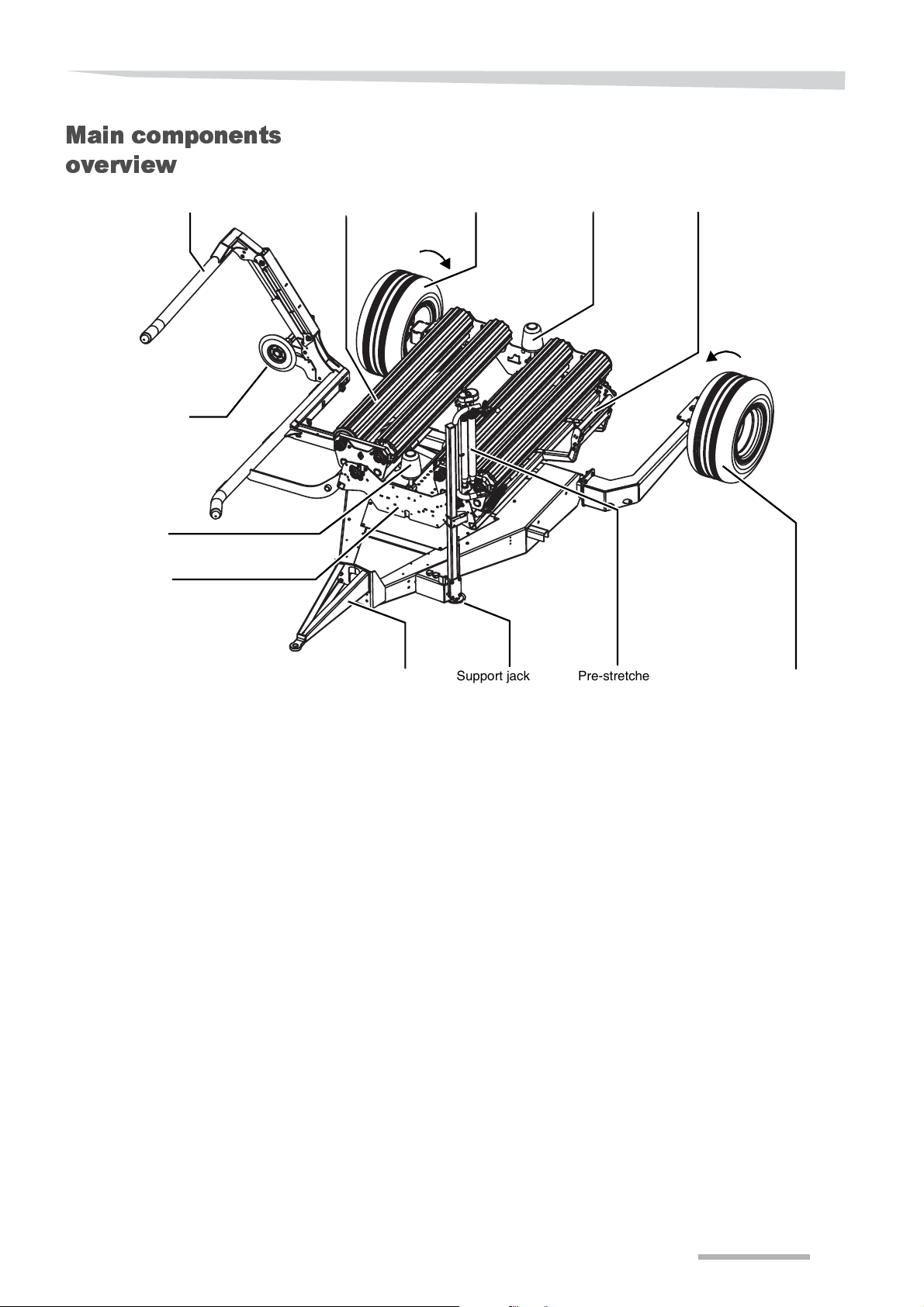
Support jack Pre-stretcher
Film cutterSupport roller
Support roller
Table roller
Drawbar
Loading arm
Wrapping table
Loading arm disc
Adjustable wheel
Adjustable wheel
Main components
overview
25
Page 26
Familiarize yourself with the machine
H
L
TW
OW
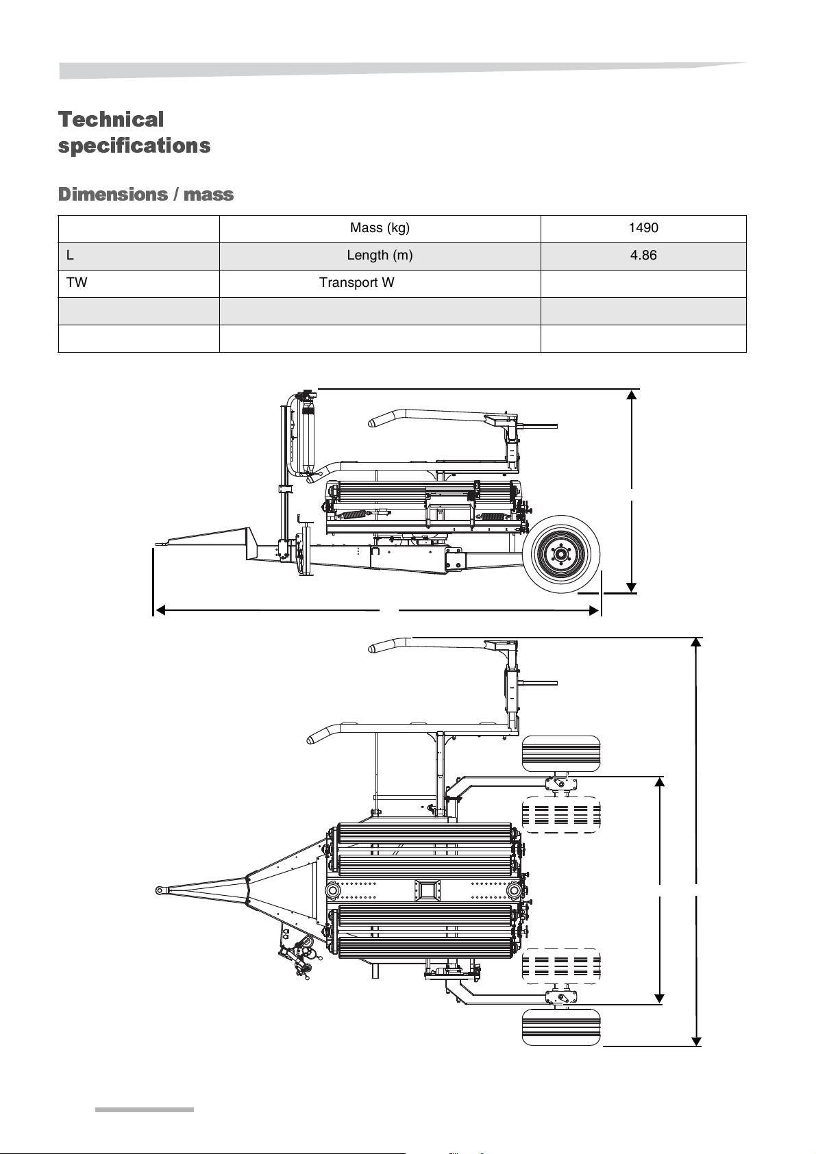
Technical
specifications
Dimensions / mass
Mass (kg) 1490
L Length (m) 4.86
TW Transport Width (m) 2.49
OW Operating Width (m) 4.45
H Height (m) 2.29
26
Page 27
Familiarize yourself with the machine
Maximum
150 cm
Maximum
100 cm
Maximum
90 cm
Machine
specifications
Number of pre-stretchers (for 750 mm film width) 1
Pre-stretcher ratio 21:37
Number of film cutters 1
Maximum table speed (rpm) 30
Tyres 15.0/55-17 10 PR-AW
Technical maximum transport speed 25 km/h
Hitch eye 40 mm standard
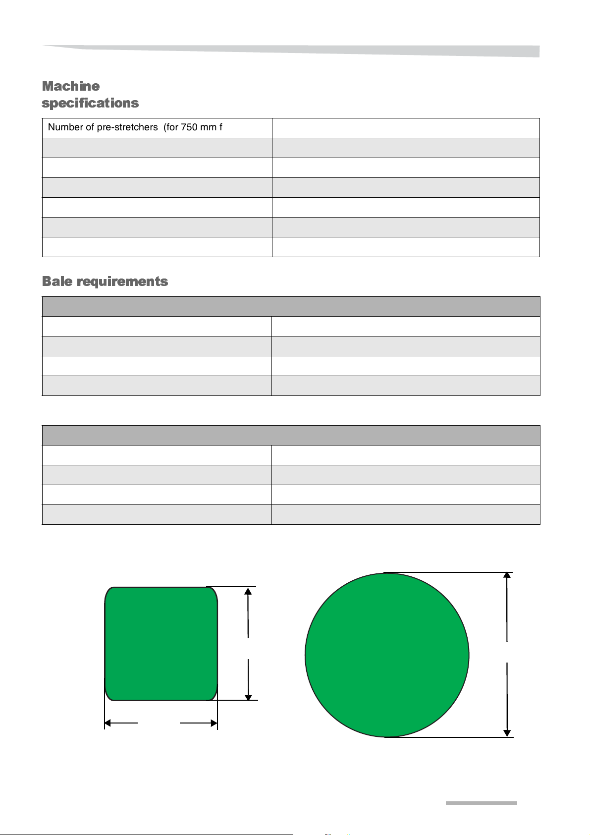
Bale requirements
Square bales
Width (cm) 70-90
Height (cm) 60-100
Maximum length, inclusive bale expansion (cm) 180
Maximum weight (kg) 900
Round bales
Minimum diameter (cm) 100
Maximum diameter (cm) 150
Maximum width (cm) 150
Maximum weight (kg) 900
27
Page 28
Familiarize yourself with the machine
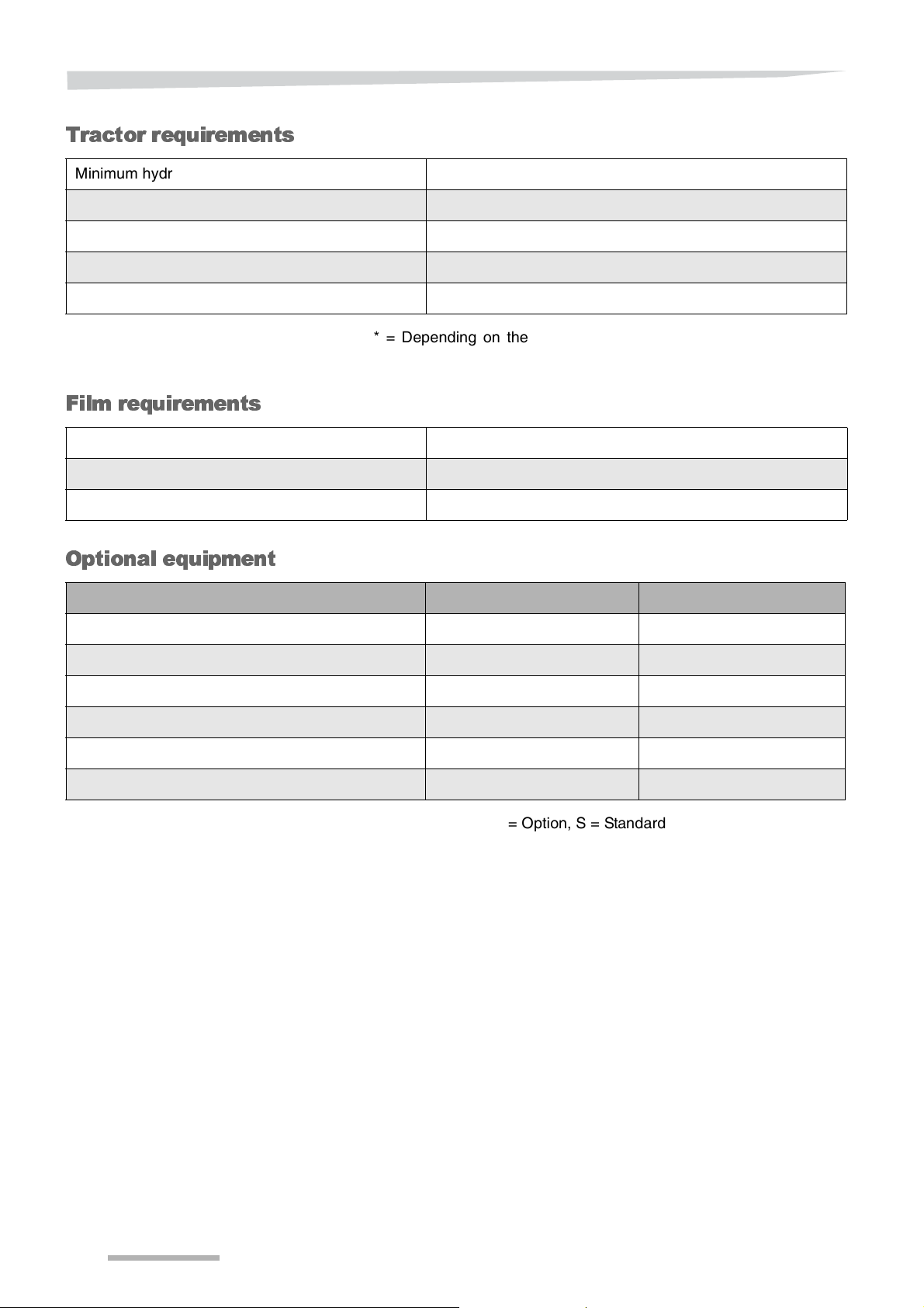
Tractor requirements
Minimum hydraulic oil flow (l/min) 26
Hydraulic oil pressure (bar) 150
Standard hydraulics 1 single acting control valve with pressureless return
Electronic power supply 12 V (DC) connector (DIN 9680)
Lighting power supply* 12 V (DC) connector, 7 pin socket (DIN ISO 1724)
* = Depending on the machine version, road lighting is not always
factory fitted.
Film requirements
Width (mm) 750
Thickness (μm) minimal 25
Quality 3 layer blown
Optional equipment
Cable Control (M) Electronic Control (C)
Automatic stop at end of film / film break - +
Gear kit pre-stretcher + +
Remote control (flashing light included) - +
Drop mat + +
Wheel chock set + +
Counterweights + +
- = Not available, + = Option, S = Standard
28
Page 29
Familiarize yourself with the machine
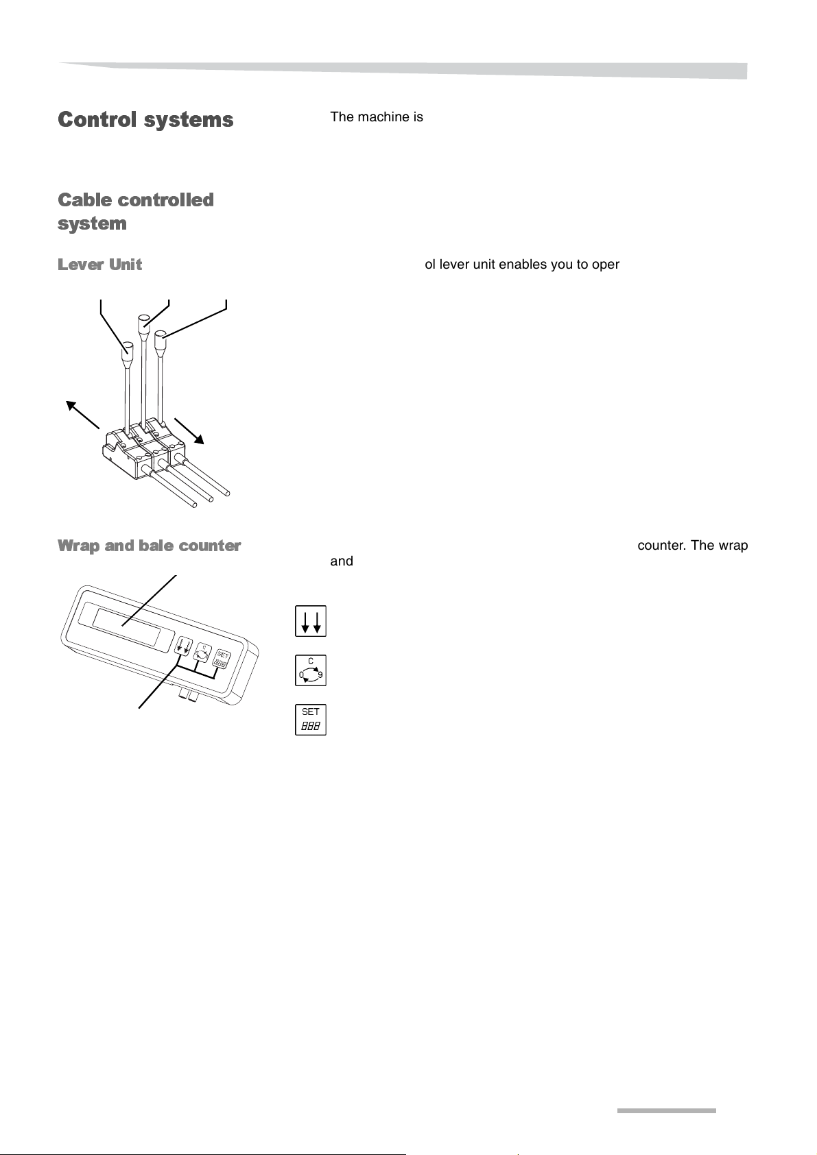
Lever 1 Lever 2 Lever 3
Backwards
Forwards
Buttons
LCD screen
Control systems
Cable controlled
system
Lever Unit
The machine is available with two different control systems:
• Cable controlled (manual) with wrap and bale counter.
• Electronic controlled.
The cable control lever unit enables you to operate the machine from
the tractor cabin.
The unit has three levers:
• Lever 1 to operate the table for unloading bales.
• Lever 2 to operate the table for film wrapping.
• Lever 3 to operate the loading arm.
Wrap and bale counter
The cable controlled version has a wrap and bale counter. The wrap
and bale counter enables supervision and fine-tuning of the bale
wrapping procedure from the tractor cabin.
Actual mode button, to browse and confirm.
Clear button, to (re)set values.
Set button, to select digits or positions.
29
Page 30
Familiarize yourself with the machine
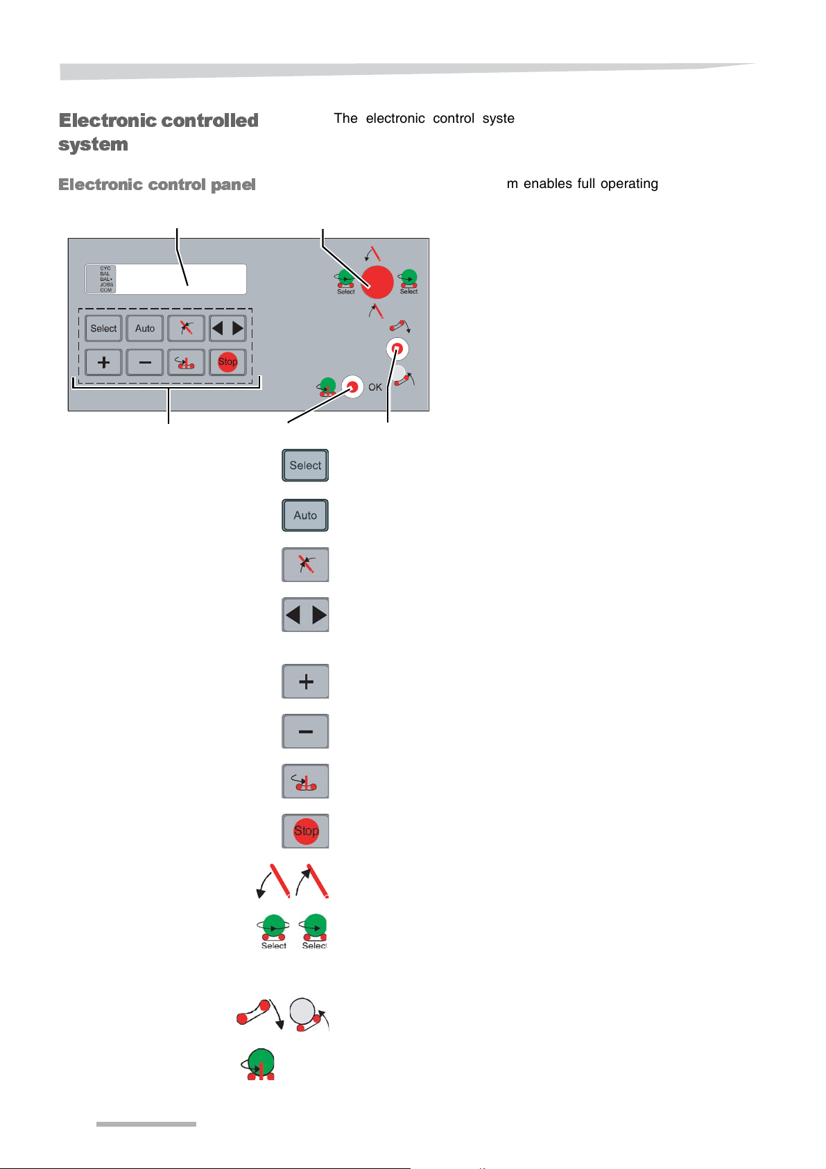
Lower toggle switch
Upper toggle switch
Display
Joystick
Buttons
Electronic controlled
system
Electronic control panel
The electronic control system consists of a control panel and a
machine box.
The electronic control system enables full operating and monitoring
the complete bale wrapping process from the tractor cabin.
Select button
To enter the parameter settings menu.
Auto button
To select the operating mode.
Loading arm neutral position button.
To place the loading arm in the loading position.
Start position button
To place the machine into the start position and to reset the revolution
counter.
Plus button
To increase a value.
Minus button
To decrease a value.
Table in loading position button
To place the table in the loading position.
Stop button
To stop or interrupt a procedure and to select the manual mode.
Joystick
Moving up and down: To lower and raise the loading arm.
Joystick
Moving left and right: To scroll through the parameter menu, to wrap
at low speed and start wrapping at low speed increasing to the normal
speed.
30
Upper toggle switch
To move the table upwards and horizontal position.
Lower toggle switch
OK
To move the table in the unloading position, to start a procedure, to
confirm (OK), to reset counters and to interrupt a process.
Page 31

Familiarize yourself with the machine
Remote control [+]
OK
For the electronic control system a remote control is available as an
accessory.
The remote control enables operating the machine from a distance.
When a button is pressed, the red LED will light up. In case the LED
does not light up, check or replace the 9V battery.
Stop button
To stop or interrupt a procedure and to select the manual mode.
OK button
To confirm (OK) and to interrupt a process.
Manual operation button
Start wrapping at low speed increasing to the normal speed.
Bale unloading button
To move the table upwards to unload a bale.
Table unloading position button
To move the table in the unloading position.
Table horizontal button
To move the table in the horizontal position.
31
Page 32

Delivery and assembly
Delivery and assembly
Check the scope
of delivery
The machine will arrive fully assembled. Check the machine after
delivery for loose or missing parts. In case parts are not assembled
please contact your dealer.
N
OTE
In case parts are missing or the machine got damaged during
transport, please submit a complaint immediately at your dealer,
importer, or the manufacturer.
Check list for parts Quantity
Operating manual 1
Spare part manual 1
Special accessories see delivery note
32
Page 33

Hitching the machine
Hitching the machine
Safety
General
Wear safety shoes
During all work at the machine never bring your feet under the
machine and always wear safety shoes. Wearing safety shoes
prevents and decreases the risk of serious injuries.
»Safety instructions«, see page 9.
Before hitching the machine always:
• Prevent the tractor and machine from rolling away.
• Switch off all hydraulic systems.
• Switch off the tractor engine.
• Remove the ignition key.
• Never stand between the tractor and the machine during hitching.
In case of negligence serious or deadly injuries can occur.
The following steps are described in this section:
• Hitching.
• Adjusting the drawbar.
• Adjusting the support jack.
• Hydraulic connections.
• Electronic connections.
• Checking the machine.
Checklist
The following steps are discribed in this section:
• Position the tractor and the machine on a firm, secure level ground.
• Secure the tractor and machine from rolling away.
• Adjust the drawbar.
• Adjust the drawbar height.
• Couple the drawbar to the tractor.
• Establish the connection of the control panel or the wrap and bale
counter to the machine box.
• Connect the hydraulic hoses.
• Connect the electronic lighting.
• Jack up and secure the support jack.
33
Page 34

Hitching the machine
BoltsNuts
36
69
DrawbarHitch eye Handle
Pin / Spring clip
Handle
Support jack
Hitchi ng
Drawbar settings
Remove the tractor lower links.
Before hitching the machine, remove the tractor lower links to avoid
them touching the drawbar. During turning, the lower links can touch
the drawbar and the machine can turn over. Personal and machine
damages can occur.
Before hitching the machine, the correct height of the hitch eye to the
tractor towing hook has to be determined.
> Place the tractor and machine in line on a firm level, with a distance
of between the towing hook and the hitch eye of about 15 cm.
The drawbar can be mounted for high and low attachment.
Hitch eye height cm
High attachment setting 69
Low attachment setting 36
> Loosen the bolts and nuts.
> Place the drawbar in the required position.
> Place 3 bolts and nuts at the left and the right side.
> Tighten the bolts and nuts with 220 Nm.
Connecting to the
tractor hook
Support jack
adjustment
The drawbar can be placed in 4 different positions:
> Turn the handle counterclockwise to the move the drawbar
upwards (and clockwise to lower the drawbar).
> Check the height of the tractor towing hook.
> Change the drawbar height if required, by placing the drawbar in
low or high attachment.
> Couple the machine to the tractor.
Place the machine in a horizontal position:
> Retract the drawbar support fully, by using the handle.
> Remove the spring clip.
> Remove the pin.
> Slide the support jack in the required position. When attached to
the tractor, this has to be the upper position.
> Place the pin.
> Secure the pin with the spring clip.
34
Page 35

Hitching the machine
Lever 1 Lever 2 Lever 3
Backwards
Forwards
Mechanical
connections
Installation of the cable control lever unit
Take care of enough free space to avoid cables from getting stretched,
twisted or torn. Stretched, twisted and torn cables can lead to
unpredictable movements of the machine which may cause serious
damages and injuries.
Install the lever unit on a support or holder in the tractor cabin.
Take care of the following:
• Ensure that the tractor operator can easily reach the lever unit.
• If possible fit the lever unit at a place in the tractor cabin with a low
vibration level.
• If possible fit the lever unit at a place in the tractor cabin with less
dust.
• Avoid sharp bends in the cables.
> Mount and connect the cable control unit at the tractor.
35
Page 36

Hitching the machine
Blue
Red
Power cable
Battery
Electr on ic
connections
Electronic lighting
Electronic control
systems
Check the cable layout
Take care of enough free space to avoid cables from getting stretched,
twisted or torn. Stretched, twisted and torn cables can lead to
unpredictable movements of the machine that may cause serious
damages and injuries.
Check cables and connections
Before connecting check all electronic cables for damages. After
connecting check the electronic cables for tight connection. Damaged
or incorrect connected plugs can cause unpredictable movements of
the machine which may result in serious damages and injuries.
Connect the 7-pin connector (DIN ISO 1724) to the road lighting
socket at the tractor.
Electronic connections of the electronic control systems
The power must always be supplied by the 3-pin 12 V plug (DIN9680).
Never connect the power cable to a 12 V cigarette lighter plug. Check
the condition of the fuse in the power cable, because of risk of electric
power cuts and malfunctioning.
The wrap and bale counter or the electronic control panel should be
mounted in an easily accessible position in the tractor cabin.
Installation of electronic
control systems
Alternative power cable
IInstall the wrap and bale counter and the electronic control panel at a
support or holder in the tractor cabin and please note following:
• That the tractor operator can easily reach the wrap and bale
counter or the electronic control panel and easily can read the
LCD-screen.
• If possible, fit the wrap and bale counter and the electronic control
panel at a place in the tractor cabin with a low vibration level.
• If possible, fit the wrap and bale counter and the electronic control
panel at a place in the tractor with less dust.
• Protect the wrap and bale counter and the electronic control panel
from direct sunlight and moisture.
Connect the main power cable to the 3-pin 12 V plug (DIN9680).
Connect the machine box to the wrap and bale counter or the
electronic control panel with the 4-pin connector.
For owners of a tractor without a 3-pin 12 V connector (DIN9680), an
alternative cable is provided for the power supply of the wrap and bale
counter or the electronic control panel.
The alternative cable is directly connected to the 12 V battery of the
tractor.
Color Pole
Red / Brown +
Blue -
36
N
OTE
In case your tractor is not provided with a 3-pin 12 V connector
(DIN9680), please contact your tractor dealer.
Page 37

Hitching the machine
Hydraulic
connections
Hydraulic connections only pressureless
Only connect hydraulic hoses to the tractor when both tractor and
machine hydraulics are pressureless. Hydraulics under pressure can
cause accidental movements of the machine with serious damage and
injuries as a result.
Searching for hydraulic oil leaks
Never search for leaks by touching hydraulic hoses and hydraulic
connections, even when your hands are protected with a protective
skin cream or oil-resistant gloves. Always use a piece of paper when
searching for leaks.
Due to high pressure and very little holes in case of leakages, the
hydraulic oil will go through protection devices and your skin! Hydraulic
oil may come into your bloodstream, which is lifethreatening!
Avoid oil mixture
If the machine is used at different tractors, improper oil mixtures can
occur, which may destroy tractor and machine parts.
Avoid entering of dirt into the hydraulic system
The hydraulic system can get seriously damaged by dirt. Personal
injuries or material damage can be caused.
Check hoses and connections
Before connecting, check all hydraulic hoses for damages. After
connecting, check all hydraulic hoses for tight connection. Defective
hydraulic hoses or incorrect positioned hydraulic connectors can
cause unforeseen movements of the machine. Serious damage or
fatal injuries can occur.
Secure tractor hydraulic devices
In transport position, secure the tractor hydraulic control devices
against unintended actuation and lock if possible. Unintended
actuation of the hydraulic device may lead to unexpected movements
of the machine. Fatal injuries and serious damage can be caused.
Check correct position and layout of hydraulic hoses
Hydraulic hoses may not be jammed or under tension. Pay attention
to sufficient play. Twisted or jammed hydraulic hoses can cause
serious injuries and damages to the machine.
Check settings of hydraulic block
Before coupling, check if the hydraulic block is adapted for the
hydraulic system of your tractor. If necessary, adapt the hydraulic
block for:
• Open centre system (standard factory setting).
• Closed centre system.
• Load sensing system.
37
Page 38

Hitching the machine
Blocking plug Main plug
Main plug
Blocking plug
Hydraulic block -
open centre
Hydraulic block -
closed centre
Cable control
Electronic control
The machine is adapted by the manufacturer for tractors with an open
centre hydraulic system.
No adjustment of the hydraulic block is necessary.
When the tractor is provided with a closed centre hydraulic system,
adjust the hydraulic blockas described below
When the machine is provided with cable control, the hydraulic block
has to be adjusted accordingly.
> Switch off the tractor hydraulics.
> Switch off the tractor engine.
> Remove the ignition key.
> Remove the main plug.
> Mount the blocking plug.
> Mount the main plug in the blocking plug.
When the machine is provided with electronic control the hydraulic
block has to be adjusted accordingly.
> Switch off the tractor hydraulics.
> Switch off the tractor engine.
> Remove the ignition key.
Hydraulic block - load
sensing
Hydraulic hoses
> Remove the main plug.
> Mount the blocking plug.
> Mount the main plug.
The machine is standardly adjusted for tractors with an open centre
hydraulic system.
No adjustment of the hydraulic block is necessary.
The oil flow of the tractor must be set to 26 l/min.
> Make sure the tractor hydraulic device is pressureless, the tractor
engine is switched off and the ignition key is removed.
> Connect the yellow marked hydraulic hose to a single acting
control valve with pressureless return.
> Connect the blue marked hydraulic hose to a single acting control
valve with pressureless return.
38
Page 39

Preparation for use
Preparation for use
Safety
Obey safety instructions
Obey the safety instructions at the execution of all work. Any disregard
for safety instructions can lead to serious or fatal injuries.
»Safety instructions«, see page 9.
Wear safety shoes
During all jobs at the machine never bring your feet under the machine
and always wear safety shoes, to decrease the risk of serious injuries.
Switch off the tractor and secure it
Never work at a running machine, make sure that:
> All hydraulic systems are switched off.
> The tractor engine is switched off.
> The ignition key is removed.
> The electronic systems are switched off.
> The tractor is secured from rolling away.
In case of negligence, serious or deadly injuries can occur.
Check all hydraulic connections
Before use, check if all hydraulic connections are fitted correctly to the
correct single acting valves with pressureless return at the tractor.
Incorrect connected hydraulic hoses can cause unpredictable
movements of the machine, which may result in serious or fatal
injuries.
Preparations
Following preparations have to be carried out before taking the
machine into use:
• Table rollers adjustment.
• Support rollers adjustment.
• Pre-stretcher adjustment.
• Film roll installation and adjustment.
39
Page 40

Preparation for use
Chain
tensioner
Spring
Bolts and
nuts
Main bolt
Nuts
Bolts Spocket
Bolts and nutsTable rollers
Nuts
Table rollers
adjustment
To ensure a proper stability of the bale during wrapping, adjust the
table rollers according to the bale dimensions.
Recommended position, depending on the bale diameter:
Round bales
diameter (mm)
- 600 Inner position (800 mm)
1000-1300 700-800-900 Middle position (900 mm)
1400-1500 1000 Outer position (1000 mm)
** = the largest size, width or height.
To adjust the position of the table rollers:
> Loosen the nuts at the chain tensioner.
> Loosen the bolts at the chain tensioner.
> Loosen the chain tensioner main bolt.
> Support the table rollers and remove the spring.
> Remove the bolts and nuts behind the sprocket at the bearing
housing.
> Remove the bolts and nuts at the bearing housing at the end of the
axle.
> Move the table rollers in the required position.
> Place back and fasten the bolts and nuts behind the sprocket
wheel at the bearing housing.
> Place back and fasten the bolts and nuts at the bearing housing at
the end of the axle.
> Place back the spring, and adjust the spring tension in such a way
that the table rollers will just not tilt.
> Place the chain tensioner in the required (tooth) position.
> Fasten the main bolt hand tight.
> Set the correct chain tension (max. 1 cm free play), by using the
chain tensioner nuts.
> Tighten the chain tensioner bolts.
> Tighten the main bolt.
Square bales Recommended
largest width (mm)**
position
40
»Torques for bolted connections«, see page 90.
Page 41

Preparation for use
C C
Support rollers
Support roller
II
II
Linch pin
Suppo rt rolle rs
adjustment
To ensure a proper stability of the bale during wrapping, adjust the
support rollers for small or large bales.
The support roller must be adjusted in such a way, that the bale is in
the middle of the table. When the bale is on the table, the clearance C
on both sides between the bale the support rollers should be
maximum 50 mm.
The support rollers can be placed in several positions for large and
small bales. The bale always have to lay in the middle at the table:
> Remove the linch pins.
> Place the roller in the required position, to adjust clearance C.
> Place and lock the linch pins.
41
Page 42

Preparation for use
Bolts
Centre line of
the bale
Pre-stretcher
Pre-s tre tc h er
adjustment
Adjust the pre-stretcher, in such a way that the centre line of the film
roll matches the centre line of the bale.
> Switch off all hydraulic systems.
> Switch off the electronic systems by disconnecting the 12V power
supply cable.
> Switch off the tractor engine.
> Remove the ignition key.
> Unscrew the bolts one turn.
> Move the entire pre-stretcher up- or downwards, depending on the
bale diameter and the kind of bales to wrap.
The film has to match the centre line of the bale.
> Tighten the bolts.
»Torques for bolted connections«, see page 90.
42
Page 43

Preparation for use
Upper
lever
Hook
Lower
lever
Prestretcher
Spring
clip
Film
Film i ns t al la tio n
Loading the film roll
Before installing a film roll:
> Switch off all hydraulic systems.
> Switch off the electronic systems by disconnecting the 12V power
supply cable.
> Switch off the tractor engine.
> Remove the ignition key.
Stay out of the pre-stretcher rollers
Stay out of the pre-stretcher rollers, because hands can be squeezed.
Injuries can occur.
> Move the lower lever to turn the film holder and secure with the
hook.
> Remove the spring clip and lift the upper lever.
> Place a film roll and take care of the correct direction of rotation of
the film roll.
> Lower the upper lever.
> Secure the lever by installing the spring clip
> Guide the film between the rollers as shown in the picture.
> Move the lower lever to release the pre-stretcher from the hook.
43
Page 44

Preparation for use
BoltSpring clipSliding tube
Loading arm disc
adjustment
Loading arm
adjustment
Checklist
The loading arm disc has to be placed in such away that a bale has to
be placed in the middle of the wrapping table.
To adjust the loading arm disc:
> Remove the spring clip.
> Remove the bolt.
> Set the sliding tube in the such a position that the bale will be
placed in the middle of the wrapping table.
> Place back the bolt and secure the bolt with the spring clip.
»Loading a bale«, see page 58.
The loading arm cannot be adjusted, only the position of the loading
arm down sensor and the loading arm field transport position sensor
can be set.
»Loading arm down sensor«, see page 118.
»Loading arm field transport position sensor«, see page 118.
> Run the tractor hydraulics at idle
• Check that all components are operating correctly.
• Check the oil circulation.
• Check for unusual noises.
> Switch off all hydraulic systems.
• Check that the components are securely tightened.
»Torques for bolted connections«, see page 90.
During the running-in period, special maintenance has to be carried
out.
»Maintenance table«, page 86.
44
Page 45

Road transport
Road transport
Safety
Before road transport will take place, please read the following safety
instructions. The compliance is mandatory and helps you to avoid
accidents.
Observe safety instructions
Observe the safety instructions for carrying out all kind of jobs. Any
disregard for safety instructions may lead to serious or fatal injuries.
»Safety instructions«, see page 9.
Switch off all electronic controls and the hydraulic circuit
Always switch off the electronic systems by disconnecting the 12V
power supply cable, and switch off all hydraulic systems. Inadvertently
operating will be prevented this way, otherwise material damages and
fatal injuries can occur.
Make sure the machine is clean before road transportation
Before transportation by road, make sure that the machine is clear and
clean from heavy dirt, remaining crop and soil. Crop, dirt or soil that
drops on the road, can cause slippery road conditions. Ensure that all
lighting equipment is free from remaining crop and dirt. Clean the
machine to avoid to traffic accidents.
Block all hydraulic valves
To avoid inadvertently activation of machine components, activate all
machanical and/or hydraulic valve locks at the machine. Also lock the
hydraulic valves at the tractor, or disconnect the hydraulic hoses for
machine operation from the tractor.
Do not transport bales
Never transport a bale at the machine, this affects steering, braking
capabilities and driving performances of the tractor and machine
combination. Personal or machine damages can occur.
Install and close all protective covers and doors
All protective covers and doors have to be installed, closed and secured
during road transportation. Material damages and personal injuries can
be caused.
Carrying people and objects on the machine is prohibited
Neither persons nor objects are allowed to be transported at the
machine at any time. Only parts stored in their dedicated storage
locations are alllowed to be transported at the machine. Riding on the
machine is hazardous and strictly prohibited.
45
Page 46

Road transport
Lever 1 Lever 2 Lever 3
Backwards
Forwards
General
conditions
Empty the
wrapping table
Cable control
You have to put the machine into the transport position before road
transport may take place.
Next steps are necessary:
• Empty the wrapping table.
• Place the wrapping table into transport position.
• Place the loading arm in transport position and lock.
• Install, close and secure all protective covers.
• Switch off the electronic systems by disconnecting the 12V power
supply cable from the tractor.
• Switch off all hydraulic systems.
• Close all hydraulic valves.
• Place the wheels into the transport position.
• Check wheels and tyres.
Before road transport may take place, the wrapping table has to be
empty.
To empty the wrapping table:
> Use lever 2 to move the table in the position that the rollers are
perpendicular to the direction of travel with the film cutter at the
front of the machine (tractor side).
> Move lever 1 backwards to unload the bale.
Electronic control
46
To empty the wrapping table:
> Move the lower toggle switch to the left to move the table in the
unloading position.
> Move the upper toggle switch down to unload the bale.
Page 47

Road transport
Lever 1 Lever 2 Lever 3
Backwards
Forwards
Lever 1 Lever 2 Lever 3
Backwards
Forwards
Wrapping table
horizontal
Cable control
Electronic control
Place the table into horizontal position before road transport may take
place.
> Move lever 1 forwards to move the wrapping table into horizontal
position.
> Move the upper toggle switch up to move the wrapping table into
horizontal position.
Wrapping table in
transport position
Cable control
Electronic control
Place the table into transport position before road transport may take
place.
• Move lever 2 forward to place the wrapping table in a position that
the table rollers are parallel to the direction of travel, with the film
cutter at the left side of the machine.
> Press the start button to place the machine in the start or transport
position.
47
Page 48

Road transport
Lever 1 Lever 2 Lever 3
Backwards
Forwards
Safety clip Safety pin
Second hole
Locking pin
Loading arm in
transport position
Cable control
Place the loading arm in the transport position before road transport
may take place.
> Move lever 3 backwards to lift the loading arm.
> Install the locking pin in the second hole as shown in the picture.
> Install the safety pin.
> Secure the safety clip.
48
Page 49

Road transport
Safety clip Safety pin
Second hole
Locking pin
Locking pinSpring clip
Special wrench
Bolt
Electronic control
> Move the joystick down to lift the loading arm.
> Install the locking pin in the second hole as shown in the picture.
> Install the safety pin.
> Secure the safety clip.
Adjustable wheels
in transport
position
To place the wheels into the transport position:
• Remove the spring clip.
• Remove the locking pin.
• Use the special wrench to rotate the wheels to the inside of the
machine.
• Place the locking pin.
• Place and secure the spring clip.
Check your wheels and tyres always before road transport may take
place.
»Axles, wheels and tyres«, see page 99.
49
Page 50

Road transport
Nut
Bolt
Hydraulic
adjustable
wheel s[+ ] in
transport position
Check the wh eels for
correct position
To place the wheels into the transport position:
> Open the hydraulic valve at the front of the machine.
> Use the hydraulic valve at the tractor to operate the hydraulic
cylinders to move the wheels to the inner side of the machine.
> Close the hydraulic valve at the front of the machine to avoid
inadvertent operating of the cylinders during road transport.
Check that the position of the wheels is exactly parallel to the direction
of travel. Adjust the position of the wheels if necessary:
> Loosen the nut at the largest bolt.
> Adapt the wheel position by adjusting the largest bolt.
> Thighten the nut.
»Torques for bolted connections«, see page 90.
Checklist
Prior to transport the machine on public roads, check if all conditions
of this checklist are met:
• All protective covers are installed, closed and secured?
• All hydraulic systems are switched off?
• All electronic systems are switched off by disconnecting the 12V
power supply cable?
• Hydraulic valves are closed?
• Remaining crop and dirt is removed?
• Lighting equipment is clean, connected and functioning?
• License plate, warning and protective equipment is present and
clean?
• Wrapping table is empty, is horizontal and in transport position?
• Wheels are in transport position and locked?
• The wheels and tyres are in a proper condition?
• Cables, hoses and tubes are routed in such a way, that they cannot
get stuck, not get tensioned or interfere with the tractor wheels
during cornering.
50
Page 51

Preparations at the field
Preparations at the fi eld
Safety
Obey the safety instructions
Obey the safety instructions at the execution of all work. Any disregard
for safety instructions can lead to serious or fatal injuries
»Safety instructions«, see page 9.
Wear safety shoes
During all jobs at or with the machine never bring your feet under the
machine and always wear safety shoes, to decrease the risk of
serious injuries.
Never work at a running machine.
Always make sure that:
> All hydraulic systems are switched off.
> The tractor engine is switched off.
> Ignition key is removed.
> The electronic systems are switched off by disconnecting the 12V
power supply cable from the tractor.
> The tractor is secured from rolling away.
In case of negligence, serious or deadly injuries can occur.
Secure the machine
Secure the machine from inadvertent moving and rolling away, the use
of wheel chocks [+] is recommended.
The machine must have a level, secure position. Unsecured or
unsupported machines can lead to serious or fatal accidents.
Change settings
Set into operating
mode
Electronic control
Only adapt the machine settings in the operating mode as described
in the sections:
• Set the machine into operating mode.
• Checklist prior to wrapping.
To set the machine in the operating mode:
• Switch on the electronic control system or the bale and wrap
counter by connecting the 12V power supply cable.
• Swtich on the hydraulic systems.
• Set the table fully horizontal.
• Place the wrapping table into the bale loading position.
• Place the loading arm in the operating mode.
• Place the wheels in the operating mode.
• Load a film in the pre-stretcher.
The machine has to be set into start position, by placing several
components in start position one by one. Only the electronic controlled
version can be set into start position by one button;
> Press the start button to position the machine in the start position.
51
Page 52

Preparations at the field
Lever 1 Lever 2 Lever 3
Backwards
Forwards
Lever 1 Lever 2 Lever 3
Backwards
Forwards
Wrapping table
horizontal
Cable control
Electronic control
Place the table into horizontal position before operation may take
place.
> Move lever 1 forwards to move the wrapping table into horizontal
position.
> Move the upper toggle switch up to move the wrapping table into
horizontal position.
Wrapping table in
operating position
Cable control
Electronic control
Place the table into operating position.
> Move lever 2 forward to place the wrapping table in such a way that
the table rollers are paralell to the direction of travel, with the film
cutter at the left side of the machine.
> Press the start button to place the machine in the start position.
52
Page 53

Preparations at the field
Safety clip Safety pin
First hole
Locking pin
Lever 1 Lever 2 Lever 3
Backwards
Forwards
Loading arm in
operating position
Place the loading arm in the start position.
> Install the locking pin in the first hole as shown in the picture.
> Install the safety pin.
> Secure the safety clip.
Cable control
Electronic control
> Move lever 3 forwards to lower the loading arm in the start position.
> Press the loading arm neutral position button to place the loading
arm in the start position or
> Move the joystick up, to lower the loading arm in the start position.
53
Page 54

Preparations at the field
BoltSpring clipLocking pin
Special wrench
Smallest Bolt Nut
Adjustable wheels
in operating
position
Hydraulic
adjustable
wheel s[+ ] in
operating position
To place the wheels into the operating position:
• Remove the spring clip.
• Remove the locking pin.
• Use the special wrench to rotate the wheels to the outer side of the
machine.
• Place the locking pin.
• Place and secure the spring clip.
To place the wheels into the operating position:
> Open the hydraulic valve at the front of the machine.
> Use the hydraulic valve at the tractor to operate the hydraulic
cylinders to move the wheels to the outer side of the machine.
> Close the hydraulic valve at the front of the machine to avoid
inadvertent operating of the cylinders during operation.
Check the wh eels for
correct position
54
Check that the position of the wheels is exactly parallel to the direction
of travel. Adjust the position of the wheels if necessary:
> Loosen the nut at the smallest bolt.
> Adapt the wheel position by adjusting the smallest bolt.
> Thighten the nut.
»Torques for bolted connections«, see page 90.
Page 55

Preparations at the field
Checklist
Before start wrapping, check if:
• All prescibed maintenance is carried out.
»Maintenance«, see page 82.
• The electronic systems are switched on by connecting the 12V
power supply.
• The hydraulic systems are switched on.
• The wrapping table is in the operating position?
• The loading arm is in the operating position?
• The wheels are in operating position?
Ensure that the machine is set for the size of the bales to wrap, also
check:
»Table rollers adjustment«, see page 40.
»Support rollers adjustment«, see page 41.
»Loading arm disc adjustment«, see page 44.
»Pre-stretcher adjustment«, see page 42.
55
Page 56

Operation
Operat ion
Safety
Obey the safety instructions
Obey the safety instructions at the execution of all work. Any disregard
for safety instructions can lead to serious or fatal injuries.
»Safety instructions«, see page 9.
Carrying people and objects on the machine is prohibited
Neither persons nor objects are allowed to be transported at the
machine at any time. Only parts stored in their dedicated storage
locations are alllowed to be transported at the machine. Riding on the
machine is hazardous and strictly prohibited.
Take care of a clear view at the machine especially when using
the remote control [+].
Always take care of a clear view at the machine and monitor the
machine during wrapping, especially when the remote control is used.
So the machine can be stopped immediately in case of emergency or
troubles. Otherwise fatal injuries and material damages can occur.
Never leave the receiving area of the remote control with the
remote controller [+].
In case the receiving area is left with the remote controller [+], the
machine can never be stopped in time in case of emergency or troubles.
Fatal injuries and material damages can occur.
Make sure the “Danger Zone“ of the machine is free from
persons and objects
Check the “Danger Zone“ of the machine before starting and
continually during operation. The “Danger Zone“ is the aera around
the wrapping table, at least 5 metres from the wrapping table and at
least 10 metres at the back of the machine.
Make sure that the operator has an adequate view of the operating
area. Only start operating if the direct surrounding is free from any
persons and objects to avoid serious or fatal injuries.
The operator is always responsible to keep persons out of the “Danger
Zone“.
56
In case the machin is used stationary it is strongly recommended to
mark out the “Danger Zone“ with pegs and mark-out ribbon. This to
avoid persons from entering the “Danger Zone“ by accidence.
Note the contour of the terrain
Pay even more attention when working on a slope. Avoid slopes on
which the combination (tractor and machine) could slip away or
overturn. Unload the bale in such a way that it can never roll away.
Serious or fatal injuries can occur.
Do not unload bales while the wheels are in transport position.
Place the wheels always in the operating postion before start
operating. Unloading bales on the wheels, while driving may cause
heavy machine damages.
Page 57

Operation
Circumference
Required film
wraps
Determination of
table revolutions
Calculation of
table revolutions
The number of bale revolutions in relation to the number of table
revolutions determines the amount of film layers the bale is wrapped
in. For grass a minimum of 6 layers is recommended, 4 layers may be
sufficient for short term storage at low temperature. It is recommended
to increase the number of layers if the bale consists of hard and stem
material.
You can choose a recommended number of film wraps, or you can
determine the number of film wraps yourself.
The settings in the table below are recommendations which will allow
a correct coverage under most circumstances. The operator is always
responsible for the correct coverage of the bale. Therefore regularly:
• Check the coverage of the bale
• Adjust the settings or parameters if necessary.
> Count the number of the table revolutions to cover the bale just
completely with film.
> Add 1 to this number.
> Multiply this with 2, for 4 layers, with 3 for 6 layers, or 4 for 8 layers
etcetera.
The table drive is set to give 2+2+2... layers overlap, using 750 mm
film.
> Determine the circumference of the bale (cm) as shown in the
picture at the left.
> Divide this value by 66.
> Round off to the nearest integer above.
> Add 2 to this value.
> Multiply this with 2, for 4 layers, with 3 for 6 layers, or 4 for 8 layers
etcetera.
Recomme nded film
wraps for round b ales
The recommended number of table revolutions in relation to the bale
diameter and the required number of film layers..
Bale diameter (cm) 4 layers 6 layers
120 16 24
150 20 30
57
Page 58

Operation
OK
X
OK
OK OK
Start position
Loading a bale
The start position is reached when:
• The loading arm is completely lowered.
• The wrapping table is horizontal
• The table rollers are parallel to the direction of travel, with the film
cutter at the left side of the machine.
Before loading a bale at the wrapping table, check if the table rollers
and the loading arm disc are set for the correct bale dimensions.
• »Table rollers adjustment«, see page 40.
• »Loading arm disc adjustment«, see page 44.
Always place a bale on the table rollers, as described below.
Incorrect loaded bales may come off during wrapping. Deadly injuries
and heavy machine damages can occur.
Grab the bale at the right manner according to the pictures at the left.
Distance X should be approximately 10 cm.
Always load a bale in the middle of the wrapping table.
A bale may never touch the support rollers. Place the bale in the correct
position before start wrapping. If the bale is not loaded by the loading
arm in the middle of the wrapping table, check and adjust the support
rollers and the loading arm disc.
»Support rollers adjustment«, see page 41.
»Loading arm disc adjustment«, see page 44.
Place the bale in such a way at the table rollers that they tilt to the middle,
as shown in the pictures at the left.
58
Page 59

Operation
If one of the table rollers does not tilt to the middle, check and adjust
the spring tension.
»Table rollers adjustment«, see page 40.
If both table rollers do not tilt to the middle, check and adjust the spring
tension of both rollers.
»Table rollers adjustment«, see page 40.
59
Page 60

Operation
Lever 1 Lever 2 Lever 3
Backwards
Forwards
Wrapping
procedure
Cable control
The wrapping procedure depends on the kind of control of the
machine:
• cable control
• electronic control
Start position: Machine in the start position.
Set the required number of film wraps:
»Parameter settings«, see page 64.
> Drive to the bale.
> Place the loading arm around the bale.
> Move lever 3 backwards, the loading arm clamps the bale and lifts
it.
> Move lever 3 forwards, to load the bale at the table and lower the
loading arm in the start position.
> Move lever 2 (slowly) forwards to start wrapping at low speed.
> Move lever 2 further forwards to increase the wrapping speed, do
not exceed the maximum speed of 30 rpm.
N
OTE
After the first lap, the magnetic valve will be actived and lever 2 will be
kept in forward position. When the machine stops, the lever moves to
its neutral position.
After the last but one number of film wraps, the buzzer sounds.
The wrapping table stops in the last lap itself. The stop position can be
set by parameter F.
»Parameter settings«, see page 64.
> Use lever 2 to move the table in the position that the rollers are
perpendicular to the direction of travel with the film cutter at the
front of the machine (tractor side).
> Move lever 1 backwards to unload the bale.
> Move lever 1 forwards to move the table into horizontal position.
> Move lever 2 forwards to move the table in the loading position.
> Drive to the next bale and repeat this procedure.
N
OTE
You may also move the table just beyond the position in which the
rollers are perpendicular to the direction of travel with the film cutter at
the front of the machine (tractor side).
> Move lever 2 backwards to rotate the table against the lock.
> Move lever 1 backwards to unload the bale.
> Move lever 1 forwards to move the table into horizontal position.
> Move lever 2 forwards to move the table in the loading position.
> Drive to the next bale and repeat this procedure.
60
Page 61

Operation
Electronic control
Manual mode
The electronic control system can be used in the following operating
modes:
• manual mode
• automatic mode
Start position: Machine in the start position.
Set the required number of film wraps.
»Parameter settings«, see page 69.
In the manual mode each process step has to be executed manually.
> Drive to the bale.
> Place the loading arm around the bale.
> Press the stop button to select the manual mode
> Move the joystick down, the loading arm clamps the bale and lifts it.
> Move the joystick upward to load the bale on the table and to lower
the loading arm.
> Move the joystick to the right to start wrapping at low speed. As
long as the joystick is kept to the right, wrapping continues at low
speed. Release the joystick to stop wrapping.
or
> Move the joystick to the left to start wrapping at low speed. After a
few seconds, the wrapping speed will increase to its normal speed.
As long as the joystick is kept to the leftt, wrapping continues at
normal speed. Release the joystick to stop wrapping.
N
OTE
The time the table rotates at low speed can be set by parameter T5.
»Parameter settings«, see page 69.
> Move the lower toggle switch to the left to place the wrapping table
in the unload position.
> Move the upper toggle switch down to unload the bale.
> Move the upper toggle switch up to move the table in horizontal
position.
N
OTE
• In case the procedure is stopped or interrupted you can always
switch to the automatic mode by pressing the auto button.
• In the manual mode, the machine will not stop when the required
number of film wraps is reached when you keep the joystick to the
right (wrapping). After the last but one number of film wraps, the
buzzer sounds. Release the joystick to stop wrapping.
61
Page 62

Operation
Automatic mode
OK
OK
OK
OK
In the automatic mode bale loading, the complete wrapping process
and bale unloading can be executed automatically. Depending on the
parameter settings, some steps have to be confirmed by using the
lower toggle switch, before wrapping will continue.
> Drive to the bale.
> Place the loading arm around the bale.
> Move the lower toggle switch to the right (OK) to start the wrapping
procedure. The bale will be loaded, wrapped and unloaded
automatically.
or
> Move the lower toggle switch to the right (OK) to confirm each step,
depending on the parameter settings.
In case the procedure has to be stopped:
> Press the stop button.
To continue an interrupted process:
> Move the lower toggle switch to the right (OK). The process will
start from the position the machine was stopped.
N
OTE
• During wrapping you can drive slowly to the next bale, place the
loading arm around the bale and tip the joystick down. The loading
arm clamps the bale and lifts the bale to the field transport position.
Move the joystick up to lower the loading arm a little if needed.
• In case the procedure is stopped or interrupted the machine
always switches to the manual mode.
62
Page 63

Wrap and bale counter
Buttons
LCD screen
Wrap and bale counter
General
Wrap and bale
counter box
Control box front
The cable controlled machine is equipped with a wrap and bale
counter. This counter monitors the wrapping process of the bale.
Furthermore the buzzer sounds when the pre-set number of film
wraps has been reached and the machine stops (Auto-stop function).
The wrap and bale counter contol panel enables supervision of the
bale wrapping procedure from the tractor cabin. Especially the
following functions can be monitored:
• Number of film wraps laps.
• Day bale counter.
• Total bale counter.
• Final lap cycle.
Buttons
Actual mode button
• Browse through parameters.
• Confirm a choice.
Clear button
• Change a value.
• Reset a value.
Set button
• Select a digit or position.
63
Page 64

Wrap and bale counter
Parameters
Parameter
settings
Cyc
The parameters can be changed if required.
> Press the actual mode button to select a parameter.
> Press the set button to select a digit.
> Press the clear button to set or reset the digit. Press the button
shortly to raise the value with 1, keep the button pressed to reset.
> Press the actual mode button to confirm.
By setting or changing parameters you can fine-tune the wrapping
process.
In the “Cycle” mode the number of film wraps can be read out or set.
Value Recommended value
2 - 99 »Required film wraps«, see page 57
> Select the Cycle mode by pressing the actual mode button until the
indicator appears behind “Cyc”.
> Keep the set button pressed until the first digit flashes.
Bal
> Press the clear button to set the digit. Every time this button is
pressed the value raises with 1.
> Press the set button for the next digit.
> Press the clear button to set the digit.
> Press the actual mode button twice to confirm.
The bale day counter displays the number of wrapped bales since last
reset. To (re)set this counter.
Value
0 - 99999
> Select the day-counter by pressing the actual mode button until the
indicator appears behind “Bal”.
> Keep the set button pressed until the first digit flashes.
> Press the clear button to set the counter. Every time this button is
pressed the value raises with 1.
> Press the set button for the next digit.
64
> PPress the clear button to set the digit.
> Press the actual mode button to confirm.
Page 65

Wrap and bale counter
Bal+
F.
0
The total bale counter displays the number of bales wrapped since the
machine is in use. This counter can not be (re)set.
Value
0 - 99999
> Select the total bale counter mode by pressing the actual mode
button until the indicator appears behind “Bal+”.
Final lap “number of wraps“.
In the final lap of the set number of film wraps, you can set the time in
which the table keeps rotating at operating speed before it stops.
Value (sec)
0.00 - 1.99
In case 0.00 is set: the table stops rotating immediately before the last
but one table lap.
In case 1.10 is set: the table rotates for 1.10 second at operating
speed in its final lap before it stops.
> Select the Cycle mode by pressing the actual mode button until the
indicator appears behind “Cyc”.
> Keep the set button pressed until the first digit flashes.
> Press the actual mode button to select the F. mode.
> Keep the set button pressed until the second digit flashes.
> Press the clear button to set the second digit. Every time this button
is pressed the value raises with 1.
> Keep the set button pressed until the next digit flashes.
> Repeat this procedure for the other digits.
65
Page 66

Electronic control system
Lower toggle
switch
Upper toggle
switch
Display
Joystick
Buttons
Electronic control system
General
Control panel
Control panel
The electronic control system offers the possibility to fine-tune the
wrapping process. The system also provides error indicating
functions.
The electronic control system excists of a control panel and a machine
box. An optional remote control [+] is availabe
The control panel enables supervision of the total bale wrapping
procedure from the tractor cabin. The main functions are:
• Automatic or manual control of the film wrapping process.
• Fine-tune the film wrapping process by (pre-)settings of
parameters.
• Wrap and bale counting.
Buttons
Select button
• To enter the parameter settings menu.
• To reset the counters.
Auto button
• To select the automatic mode.
Loading arm neuetral position button
• To move the loading arm in the start position.
Start position button
• To place the machine in the start position.
• To reset the revolution counter
Plus button
• To increase a value.
Minus button
• To decrease a value.
66
Page 67

Electronic control system
OK
Table in loading posistion button
• To place the table in the loading position.
Stop button
• To stop or interrupt a procedure.
• To select the manual mode.
Joystick
Moving up:
> To lower the loading arm.
Moving down:
> To lift the loading arm.
Moving to the left:
• Hold to start wrapping at low speed increasing to normal speed.
• Move to scroll through menus.
Moving to the right:
• Hold to wrap at low speed.
• Move to scroll through menus.
Upper toggle switch
Moving up:
• Hold to move the table into horizontal position.
Moving down:
• To unload a bale.
Lower toggle switch
Left:
• Move to place the table in the unloading position.
Right:
• Move to start a procedure.
• Move to confirm (OK)
• Move to interrupt a procedure.
• Move to reset the revolution counter.
Film cutter open
> Keep the plus button pressed and move the upper toggle switch
upwards to open the film cutter.
Wrapping table backwards
> Keep the minus button pressed and move the joystick to the right,
the wrapping table rotates backwards. (Clockwise).
67
Page 68

Electronic control system
Remote Control
OK
For the electtronic control system a remote control is available as an
accessory. The remote control enables operating the machine from a
distance.
When a button is pressed, the red LED will light up. In case the LED
does not light up, check or replace the 9V battery.
Stop button
• To stop or interrupt a procedure.
• To select the manual mode.
The function of this button is the same as the stop button on the
control panel.
OK button
• To confirm (OK)
• To interrupt a process.
The function of this button is the same as when the lower toggle switch
on the control panel is moved to the right.
Manual operation button
• To start wrapping at low speed increasing to normal speed.
As long as this button is pressed, the machine will keep on
operating. Release this button to stop the machine.
The function of this button is the same as when the joystick on the
control panel is moved to the left.
N
Bale unloading button
• To unload a bale.
The function of this button is the same as when the upper toggle
switch on the control panel is moved to the right.
Table unloading position button
• To move the table in the unloading position.
The function of this button is the same as when the lower toggle switch
on the control panel is moved to the left.
Table horizontal button
• To move the table in the horizontal position.
The function of this button is the same as when the upper toggle
switch on the control panel is moved to the left.
OTE
:
In this manual the machine is described as operated with the control
panel, instead of the remote control.
68
Page 69

Electronic control system
Parameter
settings
CYC
By changing parameters, the wrapping process can be fine-tuned or
adapted to the users’ preferences.
> Press the select button to enter the parameter settings menu.
> Move the joystick to the left to go to the previous parameter or to
the right to go to next parameter.
> Use the minus or plus button to change the value.
> Move the joystick to the left to go to the previous parameter or to
the right to go to next parameter or
> Press the auto button to store the settings and to leave the
parameter settings menu.
In the cycle menu the number of film wraps laps can be set.
Value Recommended value
1 - 100 »Required film wraps«, see page 57
> Press the select button to enter the parameter settings menu. The
value starts flashing.
> Use the minus or plus button to change the value.
BAL
OK
> Move the joystick to the left to go to the previous parameter or to
the right to go to next parameter or
> Press the auto button to leave the parameter settings menu.
The day bale counter displays the number of wrapped bales since last
rese. To reset this value:
> Press the select button to enter the parameter settings menu.
> Use the joystick to go to the day bale counter menu, the value
starts flashing.
> Move the lower toggle switch to the right (OK) to reset the counter.
The job counter will increment with 1.
»JOBS«, see page 70.
> Move the joystick to the left to go to the previous parameter or to
the right to go to next parameter or
> Press the auto button to leave the parameter settings menu.
69
Page 70

Electronic control system
BAL+
JOBS
OK
The total bale counter displays the total number of bales wrapped
since the machine is in use. This value can not be reset.
> Press the select button to enter the parameter settings menu.
> Use the joystick to go to the total bale counter.
> Move the joystick to the left to go to the previous parameter or to
the right to go to next parameter or
> Press the auto button to leave the parameter settings menu.
The job counter displays the number of jobs done.
> Press the select button to enter the parameter settings menu.
> Use the joystick to go to the job counter menu.
> Move the lower toggle switch to the right (OK) to reset the job
counter.
> Move the joystick to the left to go to the previous parameter or to
the right to go to next parameter or
> Press the auto button to leave the parameter settings menu.
Buzzer (A.)
In the buzzer menu the buzzer can be activated or de-activated.
> Press the select button to enter the parameter settings menu.
> Use the joystick to go to the buzzer counter menu, the value starts
flashing.
> Use the minus or plus button to change the setting.
Value Function
On Buzzer activated
Off Buzzer de-activated
> Move the joystick to the left to go to the previous parameter or to
the right to go to next parameter or
> Press the auto button to leave the parameter settings menu.
70
Page 71

Electronic control system
Bale loading (A1)
Automatic wrapping
(A2)
Bale loading can be included or excluded from the total procedure.
Value Function
0 Bale loading disabled
1 Bale loading enabled.
n case bale loading is disabled, bales have to be loaded on the table
with another tractor.
> Press the select button to enter the parameter settings menu.
> Use the joystick to go to the bale loading menu, the value starts
flashing.
> Use the minus or plus button to change the value.
> Move the joystick to the left to go to the previous parameter or to
the right to go to next parameter or
> Press the auto button to leave the parameter settings menu.
Automatic wrapping can be activated in the wrapping procedure;
when bale loading is finished the machine will start wrapping
automatically. This function is only applicable if “Bale loading (A1)“ is
switched on (1).
Value Function
0 Automatic wrapping de-activated
1 Automatic wrapping activated
In case automatic wrapping is de-activated in the wrapping procedure,
wrapping has to be activated by moving the lower toggle switch to the
right (OK).
> Press the select button to enter the parameter settings menu.
> Use the joystick to go to the automatic wrapping menu, the value
starts flashing.
> Use the minus or plus button to change the value.
> Move the joystick to the left to go to the previous parameter or to
the right to go to next parameter or
> Press the auto button to leave the parameter settings menu.
71
Page 72

Electronic control system
Bale unloading (A 3)
Automatic bale
unloading (A4)
Bale unloading can be switched off.
Value Function
0 Bale unloading switched off.
1 Bale unloading switched on.
n case bale unloading is switched off, the machine will not unload any
bale. Bales have to be unloaded with another tractor.
> Press the select button to enter the parameter settings menu.
> Use the joystick to go to the bale unloading menu, the value starts
flashing.
> Use the minus or plus button to change the value.
> Move the joystick to the left to go to the previous parameter or to
the right to go to next parameter or
> Press the auto button to leave the parameter settings menu.
Automatic bale unloading can be activated in the wrapping procedure;
when wrapping is finished the bale will be unloaded automatically. This
function is only applicable if “Bale unloading (A3)“ is switched on (1).
Value Function
0 Automatic bale unloading de-activated.
1 Automatic bale unloading activated.
n case automatic bale unloading is de-activated during wrapping, bale
unloading has to be activated by moving the lower toggle switch to the
right (OK).
> Press the select button to enter the parameter settings menu.
> Use the joystick to go to the automatic bale unloading menu, the
value starts flashing.
> Use the minus or plus button to change the value.
> Move the joystick to the left to go to the previous parameter or to
the right to go to next parameter or
> Press the auto button to leave the parameter settings menu.
72
Page 73

Electronic control system
Table in loading
position(A6)
Film break sensor [+]
(A7)
The wrapping table can be set to move to the loading position after bale
unloading automatically.
Value Function
0 Table not automatically to the loading position
1 Table automatically to the loading position.
> Press the select button to enter the parameter settings menu.
> Use the joystick to go to the table in loading position menu, the
value starts flashing.
> Use the minus or plus button to change the value.
> Move the joystick to the left to go to the previous parameter or to
the right to go to next parameter or
> Press the auto button to leave the parameter settings menu.
In this menu you can change the settings for the film break sensor.
Value Function
0 The machine is not equipped with a film break sensor
1 The machine is equipped with a film break sensor
> Press the select button to enter the parameter settings menu.
> Use the joystick to go to the film break sensor menu, the value
starts flashing.
> Use the minus or plus button to change the value.
> Move the joystick to the left to go to the previous parameter or to
the right to go to next parameter or
> Press the auto button to leave the parameter settings menu.
73
Page 74

Electronic control system
Flashing light (t1)
Sensor time out (t2)
In case the machine is equipped with an optional remote control, you
can set the time the flashing light starts, before wrapping starts (in
automatic mode).
> Press the select button to enter the parameter settings menu.
> Use the joystick to go to the flashing light menu, the value starts
flashing.
> Use the minus or plus button to change the value, each step is 0,1
sec.
> Move the joystick to the left to go to the previous parameter or to
the right to go to next parameter or
> Press the auto button to leave the parameter settings menu.
N
OTE
In case the machine has no flashing light, set this value to 0.0.
Otherwise the machine waits for the set time before it starts wrapping.
Due to a sensor or cable failure, some signals from the sensors may
never reach the electronic control system. To prevent the system from
waiting for a signal which never comes, a time-out period can be set.
In case of a time-out an error code appears in the display and you will
hear the buzzer.
»Error messages«, see page 109.
Loading arm upwards
(t3)
> Press the select button to enter the parameter settings menu.
> Use the joystick to go to the sensor time out menu, the value starts
flashing.
> Use the minus or plus button to change the value, each step is 1
sec.
> Move the joystick to the left to go to the previous parameter or to
the right to go to next parameter or
> Press the auto button to leave the parameter settings menu.
In this menu you can set the time in which the loading arm clamps and
lifts to its top position.
> Press the select button to enter the parameter settings menu.
> Use the joystick to go to the loading arm upwards menu, the value
starts flashing.
> Use the minus or plus button to change the value, each step is 1
sec.
> Move the joystick to the left to go to the previous parameter or to
the right to go to next parameter or
> Press the auto button to leave the parameter settings menu.
74
Page 75

Electronic control system
Loading arm time
delay (t4)
Slow motion start
(t5)
The time the loading arm continues moving down, after it passes the
loading arm down sensor, can be set in this menu.
> Press the select button to enter the parameter settings menu.
> Use the joystick to go to the loading arm time delay menu, the
value starts flashing.
> Use the minus or plus button to change the value, each step is 0,1
sec.
> Move the joystick to the left to go to the previous parameter or to
the right to go to next parameter or
> Press the auto button to leave the parameter settings menu.
In this menu you can set the time that the table rotates at low speed
before it increases to normal speed after starting a wrapping
procedure.
> Press the select button to enter the parameter settings menu.
> Use the joystick to go to the slow motion start menu, the value
starts flashing.
> Use the minus or plus button to change the value, each step is 0,1
sec.
> Move the joystick to the left to go to the previous parameter or to
the right to go to next parameter or
> Press the auto button to leave the parameter settings menu.
Table slow down (t6)
The moment the table slows down, to half speed in the last lap, can be
set. This time is the time after passing the table sensor.
> Press the select button to enter the parameter settings menu.
> Use the joystick to go to the table slow down menu, the value starts
flashing.
> Use the minus or plus button to change the value, each step is 0,1
sec.
> Move the joystick to the left to go to the previous parameter or to
the right to go to next parameter or
> Press the auto button to leave the parameter settings menu.
75
Page 76

Electronic control system
Table half speed (t7)
Table braking (t8)
The time the table rotates at half speed in the last lap can be set. After
rotating at half speed the table will be brought to a standstill.
> Press the select button to enter the parameter settings menu.
> Use the joystick to go to the table half speed menu, the value starts
flashing.
> Use the minus or plus button to change the value, each step is 0,1
sec.
> Move the joystick to the left to go to the previous parameter or to
the right to go to next parameter or
> Press the auto button to leave the parameter settings menu.
In this menu you can set the time in which the table brakes, before it
rotates to the bale unloading position.
> Press the select button to enter the parameter settings menu.
> Use the joystick to go to the table braking menu, the value starts
flashing.
> Use the minus or plus button to change the value, each step is 0,1
sec.
> Move the joystick to the left to go to the previous parameter or to
the right to go to next parameter or
> Press the auto button to leave the parameter settings menu.
Table tilting
backwards (t9)
The time in which the table tilts backwards for bale unloading can be
set in this menu.
> Press the select button to enter the parameter settings menu.
> Use the joystick to go to the table tilting backwards menu, the value
starts flashing.
> Use the minus or plus button to change the value, each step is 1
sec.
> Move the joystick to the left to go to the previous parameter or to
the right to go to next parameter or
> Press the auto button to leave the parameter settings menu.
76
Page 77

Electronic control system
Table in unloading
position (t10)
Table horizontal time
delay (t11)
In this menu you can set the time which the table stays in the
unloading position.
> Press the select button to enter the parameter settings menu.
> Use the joystick to go to the table in unloading position menu, the
value starts flashing.
> Use the minus or plus button to change the value, each step is 0,1
sec.
> Move the joystick to the left to go to the previous parameter or to
the right to go to next parameter or
> Press the auto button to leave the parameter settings menu.
In this menu you can set the time stays horizontal after bale unloading,
before a new process can be started.
> Press the select button to enter the parameter settings menu.
> Use the joystick to go to the slow motion start menu, the value
starts flashing.
> Use the minus or plus button to change the value, each step is 0,1
sec.
> Move the joystick to the left to go to the previous parameter or to
the right to go to next parameter or
> Press the auto button to leave the parameter settings menu.
No function (t12)
Pulse interval film
break sensor (t14)
No function.
In this menu the maximum time between to pulses of the film break
sensor can be set. In case this time is exceeded, a film break will be
detected.
This function is only applicable in case a film break sensor is installed.
> Press the select button to enter the parameter settings menu.
> Use the joystick to go to the pulse interval film break sensor menu,
the value starts flashing.
> Use the minus or plus button to change the value, each step is 0,1
sec.
> Move the joystick to the left to go to the previous parameter or to
the right to go to next parameter or
> Press the auto button to leave the parameter settings menu.
77
Page 78

Electronic control system
Table rotating
clockwise (t21)
Film cutter closed
(n1)
When the table stops before bale unloading it rotates clockwise
(reverse to the operating direction) for a while against the locking
plate, just before the bale will be unloaded. In this menu you can set
the time the table rotates clockwise.
> Press the select button to enter the parameter settings menu.
> Use the joystick to go to the table rotating clokcwise menu, the
value starts flashing.
> Use the minus or plus button to change the value, each step is 1
sec.
> Move the joystick to the left to go to the previous parameter or to
the right to go to next parameter or
> Press the auto button to leave the parameter settings menu.
When the wrapping procedure is started, the film cutter keeps closed
for some rotations to retain the film. In this menu you can set this
number of rotations.
> Press the select button to enter the parameter settings menu.
> Use the joystick to go to the film cutter closed menu, the value
starts flashing.
> Use the minus or plus button to change the value, each step is 1
sec.
> Move the joystick to the left to go to the previous parameter or to
the right to go to next parameter or
> Press the auto button to leave the parameter settings menu.
78
Page 79

Cleaning and care
Safety barPin
Cleaning and care
Safety
Observe the safety instructions
Definitely observe all safety instructions during all maintenance and
repair jobs. In case of negligence of the safety instructions serious or
deadly accidents can occur.
»Safety instructions«, see page 9.
Prevent the machine from inadvertent operating.
Before carrying out maintenance and repair jobs always:
• Unhitch the machine from the tractor if possible and prevent it from
rolling away.
• Disconnect all hydraulic hoses.
• Disconnect all eletronic cables.
»Unhitching the machine«, see page 81.
Otherwise always:
• Switch off all hydraulic systems.
• Switch off the electronic systems by disconnecting the 12V power
supply cable.
• Switch off the tractor engine and remove the ignition key.
• Make sure the tractor and machine are positioned on a firm and
level surface, support and prevent them from rolling away.
In case of negligence material damages and serious injuries can occur.
Caution
Always lock a tilted wrapping table with the safety bar
If it is needed to raise the wrapping table to get acces to components
for cleaning, repair or maintenance, it is obliged to use the safety bar
to lock the wrapping table. Otherwise serious or deadly accidents can
occur.
Place the top of the safety bar behind the pin as shown at the picture
at the left.
Do not clean bearings and hydraulic parts with high pressure
Be careful when cleaning with a high-pressure cleaner. Bearings,
seals, hydraulic parts and bolted joints are not waterproof. To avoid
machine damages, prevent bearings, seals, hydraulic parts and bolted
joints from water permeation.
Bright metal parts will get degreased and may start rusting. After every
cleaning, lubricate the bearings and grease bright metal parts.
No corrosive washing additives
Do not use any corrosive washing additives for cleaning. Bright metal
surfaces can be damaged.
79
Page 80

Cleaning and care
Cleaning
Pre-stretcher
roller(s)
After cleaning
After every use of the machine:
> Empty and clean the machine of all accumulated crop and dirt.
> Clean all lighting equipment, and the license plate from dirt.
Cleaning can be done with a high-pressure cleaner. Avoid bearings,
seals, hydraulic parts and bolted joins from water permeation.
Keep the pre-stretcher roller(s) clean; remove dust, crop and dirt.
> Use methylated spirit or similar to clean the rollers
After cleaning with the high-pressure cleaner
> Grease all bearings according to the maintenance instructions.
»Maintenance table«, see page 86.
> Cover the film cutter knives with an oil film. Only use approved
biodegradable oil, like rape oil.
80
Page 81

Parking and storage
Pin / Spring clip
Handle
support jack
Parking and storage
Safety
Unhitching the
machine
Obey the safety instructions
Obey the safety instructions at the execution of all work. Ignoring the
safety information can lead to serious or deadly injuries.
»Safety instructions«, see page 9.
The machine is not a toy
Store the machine in an area away from human activity. Never allow
children to play on or around the parked machine. Metal edges and
parts of the machine can lead to serious injuries.
> Place the machine on a dry, firm and level ground
> Secure the tractor from rolling away
> Disconnect the hydraulic connections and store them in the holder.
> Disconnect the road lighting plug and store it in the holder.
> Disconnect the 12 V power supply of the wrap and bale turner and
the electronic control panel from the tractor.
> If required remove the wrap and bale counter of the electronic
control panel from the tractor.
> Remove the spring clip and the pin.
> Lower the support jack fully.
> Install the pin and the spring clip.
> Correct the drawbar height by turning the handle.
> Unhitch the machine from the tractor hook.
After the season
Recommendation
• Store the wrap and bale counter and the electronic control panel in
a dry and dust free room, free from rodents, insects and martens.
At the end of the season or when the machine will be stored for a
longer period, carry out next jobs:
• Remove the film roll.
• Thoroughly clean the machine.
»Cleaning and care«, page 79.
• Carry out the prescribed maintenance jobs.
»Maintenance table«, see page 86.
• Repair or replace all damaged parts.
• Repaint any paint damages.
> Cover all bright metal parts with an oil film. Only use approved
biodegradable oil, like rape oil.
• Prevent the machine from rolling away.
81
Page 82

Maintenance
Maintenance
Safety
For all maintenance jobs:
Observe the safety instructions
Definitely observe all safety instructions during all maintenance and
repair jobs. In case of negligence of the safety instructions serious or
deadly accidents can occur.
»Safety instructions«, see page 9.
Searching for hydraulic oil leaks.
Never search for leaks by touching hydraulic hoses and hydraulic
connections, even when your hands are protected with a protective
skin cream or oil-resistant gloves. Always use a piece of paper when
looking for leaks.
Due to high pressure and very little holes in case of leakage, the
hydraulic oil will go through protection devices and your skin!
Hydraulic oil may come into your bloodstream, which is
lifethreatening!
Wear safety shoes
During all jobs at the machine, never bring your feet under the
machine and always wear safety shoes, to decrease the risk of
serious injuries.
Conditions for maintenance jobs
Only carry out maintenance jobs if you have the required expertise
and suitable tools. The absence of technical knowledge or unsuitable
tools can cause accidents or damages.
Genuine parts
Only genuine parts are specially designed and thoroughly tested for
use at this machine. The use of genuine parts will guarantee the
reliability and safety of the machine. Other products can interrupt
functioning of the machine or will make the machine unsafe. When
using non-genuine parts the warranty and liability of the manufacturer
reduces to nil and void.
Prevent the machine from inadvertent operating.
Before carrying out maintenance and repair jobs always:
• Unhitch the machine from the tractor if possible and prevent it from
rolling away.
• Disconnect all hydraulic hoses.
• Disconnect all eletronic cables.
»Unhitching the machine«, see page 81.
Otherwise always:
• Switch off all hydraulic systems.
• Switch off the electronic systems by disconnecting the 12V power
supply cable from the tractor.
• Switch off the tractor engine and remove the ignition key.
• Make sure the tractor and machine are positioned on a firm and
level surface, support and prevent them from rolling away.
In case of negligence material damages and serious injuries can occur.
82
Page 83

Maintenance
Safety barPin
For some maintenance jobs it is necessary to switch on hydraulic and/
or electronic power, in this case this is mentioned separately.
Always apply the rules below to prevent the machine from
inadvertently operating:
• Stop the electronic control systems from operating in the automatic
mode.
• Switch off the hydraulic power, if electronic power is needed.
• Switch off the electronic power by disconnecting the 12V power
supply cable from the tractor, if hydraulic power is needed.
Always lock a tilted wrapping table with the safety bar
If it is needed to raise the wrapping table to get acces to components
for cleaning, repair or maintenance, it is obliged to use the safety bar
to lock the wrapping table. Otherwise serious or deadly accidents can
occur.
> Place the top of the safety bar behind the pin as shown at the
picture at the left.
Prior to carry out welding jobs
Unhitch the machine from the tractor if possible and prevent it from
rolling way before start welding. Otherwise always:
• Switch off all hydraulic systems.
• Switch off the electronic control system by disconnecting the 12V
power supply cable.
• Switch off the tractor engine and remove the ignition key.
• Disconnect all electronic and hydraulic connections from the
tractor to ensure the safety when carrying out welding jobs at the
attached machine.
In case of negligence material damages and serious injuries can
occur.
Climbing aids
Use suitable climbing aids only, never use components of the machine
as a climbing aid.
83
Page 84

Maintenance
Protection measures
Additives in oil and lubricants may have harmful effects to health. Be
always aware of the safety instructions, warnings and cautions
mentioned at the original package of the oil and lubricants.
Additives in oil and lubricants can have, under circumstances, harmful
effects to health. Because an indication according to the danger order
is not necessary, therefore pay attention to:
Avoid skin contact
Avoid skin contact with oil and lubricants. Always use a protective skin
cream or oil-resistant gloves. Skin contact can lead to skin diseases.
Discard contaminated cleaning cloths
Discard all oil contaminated cleaning cloths immediately. Oils may
cause damages to your health.
N
OTE
• Collect wasted oil, lubricants and oil contaminated cloths, and
dispose them according to local and national environmental
regulations.
• In case skin damages occur caused by oil or lubricants, contact a
doctor immediately.
84
Page 85

Maintenance
General
Directions
Direction Description
Left Counterclockwise
Right Clockwise
Rotation around a horizontal axis As seen at right angles to the direction of travel from left to right
Rotation around a vertical axis As seen from top to bottom
Maintenance term s
Task Explanation
Grease Apply grease to the sliding surface by using a brush
At all maintenance tasks, secure the machine in the operating
position. In case the transport position is required, this is mentioned
separately.
Direction specifications (left, right, front, rear) are always meant in
relation to direction of travel.
In the table below you will find some short explanations of the most
common maintenance tasks.
Lubricate One or two presses with a grease gun, unless stated otherwise.
Oil Apply an oil film to the sliding face
Replenish Fill up fluids, oil or lubricants to the indicated maximum level.
Replace Remove a part and install a new part. Drain fluids, oils or lubricants
and replenish to the indicated maximum level.
Check Check the condition of parts and components, and replace if
necessary. Check the levels of all fluids, oils and lubricants,
replenish to the indicated maximum level if necessary.
Oil and lubricants
specifications
Lubricant Specifications
Oil Class NLGI2, K2k in accordance with DIN51825
Grease Multipurpose
85
Page 86

Maintenance
Maintenance table
»Complete machine«
»Complete machine«
»Safety decals«
»Flashing light[+]«
»Road lighting«
»Road lighting«
»Bolted connections«
»Bolts and nuts«
»Drawbar bolts and nuts«
»Wheel nuts«
»Film wrapper«
»Pre-stretcher rollers«
»Pre-stretcher rollers«
»Pre-stretcher gears«
»Film cutter«
»Film cutter cylinder«
»Film cutter knive«
»Film cutter knive«
»Sliding tube«
»Hydraulic components«
»Hydraulic hoses«
»Hydraulic hoses«
»Hydraulic block - oil filter«
Before carry out maintenance or repairs always:
• Empty the wrapping table.
• Clean the machine.
»Cleaning and care«, see page 79.
• Obey all safety instructions.
»Safety instructions«, see page 9.
»Safety«, see page 82.
• Obey all protection measures.
• »Protection measures«, see page 84
.
Oil
Check
Tighten
Replace / Change
After the first 5 hour
Every 10 hours
After the first 10 hours
Every 50 hours
road transport
Every 150 hours
Before operation and/or
Grease
Every 2 years
After operation
At the start of each seson
At the end of each season
Every 6 years
Lubricate
• • • •
••• •
• • •
•• •
• • • • •
• • • •
•• •
• • • •
• • • •
•• •• •
• • • •
• • • •
•• •
• • •
•• • •
• • •
••
• •
Clean
Page
88
88
88
88
88
89
89
89
91
91
91
92
92
92
92
93
93
93
86
Page 87

Maintenance
»Wrapping table«
»Drive chains«
»Drive chains«
»Table roller drive chains«
»Table roller drive chains«
»Table roller bearings«
»Table gears«
»Table hinges«
»Table cylinder«
»Spring tensioner«
»Loading arm«
»Loading arm hinges«
»Loading arm cylinders«
»Loading arm disc«
»Drawbar«
»Hitch eye«
»Drawbar support«
»Axles, wheels and tyres«
»Axles«
»Wheel hub bearing«
»Rims«
»Tyres«
»Sensors«
»Table rotation/unload position
sensor«
»Loading arm down sensor«
»Loading arm field transport posi-
tion sensor«
»Table horizontal sensor«
»Film break sensor [+]«
»Infra red receiver [+]«
Oil
Grease
Lubricate
After the first 5 hour
After the first 10 hours
Every 10 hours
Every 50 hours
Every 2 years
road transport
Before operation and/or
After operation
At the start of each seson
At the end of each season
Every 150 hours
Every 6 years
• • • •
•• • •
• • • •
•• • •
• • • •
•• • •
• • • •
•• • •
• • •
• • • • •
•• • ••
• • •
• •
•••
• • •
••
• •
••• •
• • •
•• •
• • •
•• •
• • •
•• •
Page
Check
Tighten
Clean
Replace / Change
94
94
94
94
95
95
95
96
96
97
97
97
98
98
99
100
100
101
102
102
102
102
102
102
87
Page 88

Maintenance
Comp le te machine
Safety decals
Flashing light[+]
Clean the machine always:
• After operation.
• At the start of each season.
• At the end of each season.
• Before storage.
»Cleaning and care«, see page 79.
»Parking and storage«, see page 81.
Keep all safety decals clean and legible. In case safety decals are
damaged, perished or lost, order new decals as spare parts and affix
them to the machine.
»Safety decals«, see page 10.
Always clean the machine before checking the safety decals.
»Cleaning and care«, see page 79.
Check the safety decals:
• After operation.
• At the start of each season.
• At the end of each season.
Check the flashing light for proper working:
• Before operation.
• At the start of each season.
Repair a defect flashing light immediately.
Road lighting
Check road lighting for proper working:
• Before operation.
• At the start of each season.
Repair defect road lighting immediately.
Clean all lighting equipment and the license plate:
• Before operation.
• After operation.
• At the start of each season.
• At the end of each season.
88
Page 89

Maintenance
BoltsNuts
Bolted
connections
Bolts and nuts
Drawbar bolts and
nuts
Replace a missing or broken bolt or nut, always by a genuine part.
Standard bolts and nuts may look the same, but can have different
qualities and properties. Non-genuine parts may change the
properties of the machine, and may make the machine unsafe.
Material damages or serious injuries can occur.
Always use a suitable torque wrench to tighten bolts and nuts.
Always check for missing bolts and nuts, install new bolts and nuts if
necessary.
Tighten all bolts and nuts:
• After the first 5 operating hours.
• After the first 10 operating hours.
• Every 150 operating hours.
• At the start of each new season.
• After a bolt or nut has been unscrewed.
»Torques for bolted connections«, see page 90.
Tighten the drawbar bolts and nuts:
• After the first 5 operating hours.
• After the first 10 operating hours.
• Every 10 operating hours.
• At the start of each new season.
• After a bolt or nut has been unscrewed and has been placed back/
replaced.
• Thighten the bolts and nuts to 220 Nm.
Wheel nuts
Thighten all wheel nuts:
• After the first 10 operating hours.
• Every 150 operating hours.
• At the start of each new season.
• After a wheel has been removed and placed back.
Thighten the wheel nuts to 220 Nm.
89
Page 90

Maintenance
Torques for bolted
connections
All bolted connections have to be tightened according to this table,
unless stated otherwise. All bolts used at this machine have a
minimum quality of 8.8 (mentioned at the bolt head).
Thread Torque value Size of
jaw*
8.8 10.9 12.9
Nm mm
M3 1.3 1.8 2.1 6
M4 2.9 4.1 1.9 7
M5 5.7 8.1 9.7 8
M6 9.9 14 17 10
M8 24 34 41 13
M10 48 68 81 17 (15)
M12 85 120 145 19 (17)
M14 135 190 225 22 (19)
M16 210 290 350 24 (22)
M18 290 400 480 27
M20 400 570 680 30
M20 x 1.5 - 640 - 30
M22 550 770 920 32
M24 700 980 1180 36
M27 1040 1460 1750 41
M30 1410 1980 2350 46
M33 1910 2700 3200 50
M36 2450 2550 3060 55
M39 3200 4500 5400 60
* Values in brackets: spanner size for locking bolts and nuts with
toothed flange.
N
OTE
• The values listed apply to dry or slightly lubricated connections.
• Do not use galvanized (plated) bolts and nuts without grease.
• When using a stiff grease, reduce the value in the table with 10%.
• When using (self-)locking bolts and nuts increase the value in the
table with 10%.
90
Page 91

Film wrapper
Rollers
Cover
Knobs
Maintenance
Pre-stretcher rollers
Pre-stretcher gears
Check the pre-stretcher rollers for rotating smoothly (check by hand):
• After the first 10 operating hours.
• Every 50 operating hours.
• At the start of the season.
Clean the pre-stretcher rollers:
• After the first 10 operating hours.
• Every 50 operating hours.
• At the start of each season.
• After operation.
»Cleaning and care«, see page 79.
Grease the pre-stretcher gears:
• After the first 10 operating hours.
• Every 50 operating hours.
• At the start of each season.
The pre-stretcher gears are protected by a cover.
> Unscrew the knobs.
> Remove the cover.
> Grease the pre-stretcher gears with use of a brush.
> Place back the cover.
> Place back and tighten the knobs.
91
Page 92

Maintenance
Film cutter cylinder
Film
cutter
knive
Sliding
tube
Film c u tt er
Film cutter cylinder
Film cutter knive
Check the flim cutter cylinder for wear, play and leakage:
• After the first 10 operating hours (leakage only).
• Every 50 operating hours.
• At the start of each season.
Clear the film cutter knive from dirt and remaining crop:
• After operation.
• At the start of each season.
Check the condition of the film cutter knive:
> Before operation
> At the start of eacht season.
Replace a dull of damaged knife
»Replace the knife«, see page 118.
Sliding tube
Grease the sliding tube:
• After the first 10 operating hours.
• Every 10 operating hours.
• At the start of each season.
• After cleaning with a high pressure cleaner.
92
Page 93

Maintenance
Hydraulic
components
Hydraulic hoses
Hydraulic oil under pressure
Before carry out any maintenance, always make the hydraulic system
pressureless. Oil under pressure may cause serious or deadly
accidents.
Always comply with all safety warnings and safety instructions
»Safety instructions«, see page 9.
»Safety«,see page 82.
Protection measures.
Always use a protective skin cream or oil-resistant gloves when
working with hydraulics.
»Protection measures«,see page 84.
Always check all hydraulic hoses and hydraulic connections for
damages and leakages:
• Before operating the machine.
• At the start of each season.
• After replacing a hydraulic component.
»Searching for hydraulic oil leaks.«,see page 82.
Hydraulic hoses age without any visible indication, therefore replace
all hydraulic hoses:
• Every six years.
Hydraulic block - o il
filter
Only the electronic controlled version is equipped with an hydraulic oil
filter. This filter is situated near the hydraulic valve block.
Replace the filter element:
• Every 2 years.
93
Page 94

Maintenance
Chain
tensioner
Nuts
Bolts
Bolt Locking plate
Wrapping table
Drive chains
Both drive chains should have a little play (approximately 1 cm), check
the chain tension:
• After the first 10 operating hours.
• Every 50 operating hours.
• At the start of each season.
Correct the chain tension if necessary:
• Loosen both nuts and set the chain tension.
• Tighten the nuts.
»Torques for bolted connections«, see page 90.
In case the chain tensioner is at the end of its range:
• Loosen the bolts of the chain tensioner.
• Place the tensioner in an other (tooth) position.
• Thighten the chain tensioner bolts.
• Loosen both nuts and set the chain tension.
• Tighten the nuts.
»Torques for bolted connections«, see page 90.
Oil both drive chains:
• After the first 10 operating hours.
• Every 50 operating hours.
• At the start of each season.
• After cleaning with a high pressure cleaner.
Table roller drive
chains
Both table roller drive chains should have approximately 1 cm free
play, check the chain tension:
• After the first 10 operating hours.
• Every 50 operating hours.
• At the start of each season.
Correct the chain tension if necessary:
• Loosen the bolt.
• Pull the locking plate a little.
• Move the sprocket up or down to adjust the chain tension.
• Place the locking plate.
• Tighten the bolt.
»Torques for bolted connections«, see page 90.
Oil both roller drive chains:
• After the first 10 operating hours.
• Every 50 operating hours.
• At the start of each season.
• After cleaning with a high pressure cleaner.
94
Page 95

Maintenance
Lubrication points
Table gears
Lubrication point
Table roller bearings
Table gears
Use a grease gun to press grease into the lubrication points:
> After the first 10 operating hours.
> Every 50 working hours.
> At the start of each season.
> After cleaning with a high pressure cleaner.
Use a grease gun to press grease into the lubrication points:
> After the first 10 operating hours.
> Every 50 working hours.
> At the start of each season.
> After cleaning with a high pressure cleaner.
Table hinges
Use a grease gun to press grease into the lubrication points at both
sides of the machine:
> After the first 10 operating hours.
> Every 50 working hours.
> At the start of each season.
> After cleaning with a high pressure cleaner.
95
Page 96

Maintenance
Table cylinder
Lubrication point
Table cylinder
Spring tensioner
Check the table cylinder for wear, play and leakage:
• After the first 10 operating hours (leakage only).
• Every 50 operating hours.
• At the start of each season.
• After cleaning with a high pressure cleaner (leakage only).
Use a grease gun to press grease into the lubrication point:
> Every 150 working hours.
> At the start of each season.
> After cleaning with a high pressure cleaner.
96
Page 97

Loading arm
Lubrication points
Lubrication points
Lubrication points
Lubrication points
Sliding tube
Maintenance
Loading arm hinges
Loading arm
cylinders
Use a grease gun to press grease into the lubrication points:
• After the first 10 operating hours.
• Every 50 operating hours.
• At the start of each season.
• After cleaning with a high pressure cleaner.
Check the hinges on wear and play:
• Every 50 operating hours.
• At the start of each season.
Check the loading arm cylinders for wear, play and leakage:
• After the first 10 operating hours (leakage only).
• Every 50 operating hours.
• At the start of each season.
• After cleaning with a high pressure cleaner (leakage only).
Loading arm disc
Use a brush to lubricate the sliding tube:
• At the start of each season.
• At the end of each season.
• After cleaning with a high pressure cleaner.
97
Page 98

Maintenance
Sliding face
Drawbar
Hitch eye
Drawbar support
Check the hitch eye for damages and wear:
• Every 50 operating hours.
• At the start of each season.
Use a grease gun to press grease into the lubrication points:
• Every 150 operating hours.
• At the start of each season.
• After cleaning with a high pressure cleaner.
Grease the support contact face with use of a brush:
• Every 150 operating hours.
• At the start of each season.
• After cleaning with a high pressure cleaner.
98
Page 99

Maintenance
Lubrication point
Lubrication points
Lubrication point
Axles, wheels and
tyres
Axles
Adjustable wheels
Repairs only by professionals
Mounting and replacing wheels and tyres requires sufficient
knowledges and the availability of special tools and equipment.
Serious personal injuries or machine damages can occur.
Tyre dimensions
Do not fit tyres with dimensions other than prescribed. Personal
injuires or machine damages can occur.
Secure the machine
When carrying out maintenance jobs at the axles, wheels and tyres
make sure that the machine:
• Is safely placed at a firm level ground, use the drawbar support.
• Is secured from rolling away. It is recommended to use wheel
chocks[+].
Check the axles for damages and cracks:
• Before operation and road transport.
• At the start of each season.
Use a grease gun to press grease into the lubrication points:
• After the first 10 operating hours.
• Every 50 operating hours.
• At the start of each season.
• After cleaning with a high pressure cleaner.
Hydraulic adjustable
wheels[+]
Use a grease gun to press grease into the lubrication points:
• After the first 10 operating hours.
• Every 50 operating hours.
• At the start of each season.
• After cleaning with a high pressure cleaner.
99
Page 100

Maintenance
Wheel hub bearing
Wheels
Rims
Wheel nuts
Let your dealer change the grease in the wheel hub bearings:
• At the start of each season
or
• At least once a year.
Let your dealer check for play of the wheel hub bearings:
• At the start of each season
or
• at least once a year.
Check the rims for damages and cracks:
• Before operation and road transport.
• At the start of each season.
In case of damages and cracks, let your dealer replace the rim.
Thigthen the wheel nuts regularly.
»Wheel nuts«, see page 89.
100
 Loading...