

KUHN MOUNTED MINOTOR 3050, SEMI-MOUNTED MINOTOR 3050, BELT-DRIVEN MINOTOR 3060 Operator's Manual
Page 1
OPERA TOR’S MANUAL
SILAGE LOADER / STRAW BLOWER / DISTRIBUTOR
MOUNTED MINOTOR 3050
SEMI-MOUNTED MINOTOR 3050
BEL T -DRIVEN MINOTOR 3060
PLEASE READ CAREFULL Y BEFORE USING THE MACHINE
AN067A GB 02-2008
1
Page 2

IMPORTANT INFORMATION
The KUHN machine that you have just purchased has undergone a full range of inspections throughout
the manufacturing process. If you should encounter a fault in spite of all the care given to the manufacture of your machine, please contact your dealer who will solve the problem with the assistance of our
after-sales service.
To enable us to satisfy your requirements, please provide the information below when you call us. It
will only take you a few minutes to fill in this page when your machine is delivered but it will save you
a lot of time in the event of a problem.
1- GENERAL DATA
Note the machine references here.
KUHN
MINOTOR
Type of machine Sequence number in the series Date commissioned
2 - OPTIONAL EQUIPMENT
Tick the boxes corresponding to the options fitted to your machine.
Slip clutch and overrun wide angle PTO shaft Narrow wheels for abrasive ground
Self contained hydraulic system Mixing hopper
Anti-clogging for rectangular bales
Manufacturer’s address: KUHN-AUDUREAU S.A., B.P . 19, F 85260 LA COPECHAGNIERE
2
Page 3

TABLE OF CONTENTS
MESSAGE TO THE USER __________________________________________ 4
SAFETY INSTRUCTIONS __________________________________________ 5 - 10
SAFETY LABELS ________________________________________________ 12
LIGHTING EQUIPMENT ___________________________________________ 14
DESCRIPTION OF THE MOUNTED MINOTOR 3050 __________________ 16
DESCRIPTION OF THE SEMI-MOUNTED MINOTOR 3050
AND THE BELT-DRIVEN MINOTOR 3060 _____________________________ 18
TECHNICAL SPECIFICATIONS ______________________________________ 20
DESCRIPTION OF THE CONTROLS _________________________________ 24
Mounted/Semi-Mounted MINOTOR 3050 Remote Control Cables ____________ 2 4
Minotor 3060 Remote Control Cables __________________________________ 27
STARTING UP ___________________________________________________ 30
Hitching _________________________________________________________ 30
Adjusting the Position of the Controls ___________________________________ 33
Transmission ______________________________________________________ 34
Connections _____________________________________________________ 35
Preliminary Checks _________________________________________________ 3 7
No-Load Tests _____________________________________________________ 38
Unhitching ________________________________________________________ 38
OPERATION _____________________________________________________ 39
Silage Loading ____________________________________________________ 39
Loading Bales _____________________________________________________ 40
Transport _________________________________________________________ 41
Distribution from a Mounted/Semi-Mounted MINOTOR 3050 _________________ 41
Distribution from a Belt-Driven MINOTOR 3060 ___________________________ 45
Using a Belt-Driven Beater Bar_________________________________________ 46
OPTIONS ________________________________________________________ 47
Free Wheel wide angle PTO shat _____________________________________ 48
Mixing Hopper + Electronic Proportioning Device __________________________ 48
Tyres _____________________________________________________________ 49
Anti-Clogging Kit for Rectangular Bales __________________________________ 50
Hydraulic Unit ______________________________________________________ 51
MAINTENANCE __________________________________________________ 54
Conveyor Chain Tension _____________________________________________ 55
Maintenance Schedule ______________________________________________ 56
Oil Change ________________________________________________________ 57
Storage ___________________________________________________________ 57
TROUBLESHOOTING GUIDE ______________________________________ 58
WARRANTY ______________________________________________________ 61
3
Page 4

DEAR OWNER,
In buying a KUHN machine you have chosen wisely . Into it have gone years of thought, research and
improvements. You will find, as have thousands of owners all over the world, that you have the best
that engineering skill and actual field testing can produce. You have purchased a dependable machine, but only by proper care and operation can you expect to receive the performance and long
service built into it.
This manual contains all the necessary information for you to receive full efficiency from your machine. The performance you get from this machine is largely dependent upon how well you read and
understand this manual and apply this knowledge. This is a simple machine but in which causes for
trouble are often overlooked even though apparent. These troubles are normally shown in poor work,
though they are largely due to natural wear of parts not being in original adjustment conditions. Therefore,
please DO NOT ASSUME THA T YOU KNOW HOW TO OPERA TE AND MAINT AIN YOUR MACHINE
before reading this manual carefully .
KEEP THIS MANUAL AV AILABLE FOR REFERENCE.
Y our KUHN dealer will instruct you on the general operation of your machine. He want s you to get the
best performance possible and will be glad to answer any special questions that may arise regarding
the operation of the KUHN machine.
Your KUHN dealer can offer a complete range of genuine KUHN service parts.
These parts are manufactured and carefully inspected in the same factory that builds the machine to
assure high quality and accurate fitting of any necessary replacements.
ABOUT IMPROVEMENTS
KUHN is continually striving to improve its products and, therefore, reserves the right to make
improvements or changes when it becomes practical to do so, without incurring any obligations to
make changes or additions to the equipment sold previously .
4
Page 5

SAFETY
The symbol above is used throughout this manual each time recommendations are made concerning
your safety , the safety of others, or the good operation of the machine.
These recommendations must be made known to all machine operators.
DESIGNATED USE OF THE MACHINE
MINOTOR 3050 and MINOTOR 3060 silage loader/distributor/straw blower machines must only be
used for the jobs for which they have been designed.
- Silage loading, loading of round or rectangular bales, transport, distribution of forage and straw
blowing for bedding down.
The manufacturer can not be held liable for any damage resulting from using the machine in ways
other than those specified by the manufacturer.
Any use other than the designated operation is at the risk and responsibility of the operator .
Designated use of the machine also means :
- following operation, maintenance and repair recommendations given by the manufacturer ;
- using only genuine spare parts, equipment and accessories as designated by the manufacturer.
MINOTOR 3050 and MINOTOR 3060 silage loader/distributor/straw blower must only be used, serviced
and repaired by skilled persons who are familiar with the characteristics and operating modes of the
machine. These persons must also be aware of the dangers to which they are exposed.
The operator must imperatively respect current legislation concerning :
- accident prevention,
- work safety,
- public traffic circulation.
All safety advice indicated on the machine must be strictly observed.
The manufacturer cannot be held liable for any damage resulting from machine modifications carried
out by the operator himself or by a third party without previous written agreement from the manufacturer.
GENERAL SAFETY RECOMMENDATIONS
Before operating the machine, always ensure that tractor and machine conform with work safety and
road traffic regulations.
5
Page 6

GENERAL POINTS
1. In addition to the instructions contained in this manual, comply with safety and accident prevention
legislation.
2. Warnings affixed to the machine provide indications on safety measures to be applied and help to
avoid accidents.
3. When driving on public roads, follow the Highway Code in your country.
4. Before starting work, the user must familiarise himself with the machine’s operating controls and
their respective functions. Once work has begun, it will be too late.
5. The user must avoid wearing loose clothing which may get caught up in a moving part.
6. The use of a tractor with a safety cab is recommended.
7. Before switching on the machine and starting work, check around the machine (beware of
children!).Make sure that you have sufficient visibility! Keep people and animals away from the
danger area of the machine (risk of projection!).The machine must be used by one person only .
8. It is strictly prohibited to use the machine to carry persons or animals whilst in operation or transit.
9. The machine must only be hitched to the tractor at the points provided in accordance with the
safety standards in force.
10. When hitching and unhitching the machine, put the stand or stands in the correct position and the
loading device in the inoperative position (arm lowered, grab retracted).
1 1 . Take great care when hitching the machine to the tractor and when uncoupling it.
12. Before hitching the machine, make sure that there is sufficient ballast on the front axle of the
tractor. Ballast should be added to the special supports according to the tractor manufacturer ’s
instructions. The front axle load must be not be less than 20% of the unladen tractor weight.
13. Do not exceed the maximum axle weight and the gross vehicle weight rating.
14. Do not exceed the maximum vehicle gauge allowed on public roads.
15. Before entering public roads, make sure that all guards and signalling devices (lights, reflectors,
etc.) required by law are fitted and working properly .
16. All remote controls (cords, cables, linkages, etc.) must be positioned such that they cannot
accidentally set off an operation which may lead to a risk of accident or damage.
17. Before entering public roads, put the machine into the transport position in accordance with the
manufacturer’s instructions (arm and grab retracted, body in the transport position, delivery chute
and cover folded back).
18. Never leave the driver’s position while the tractor is running.
19. You should always adapt your speed and driving to the track, road or land. Avoid sudden changes
of direction in all circumstances.
6
Page 7

20. Beware! Before operating the loading device (arm and grab), unfolding the cover or raising the
body , make sure that there can be no accidental contact with a power line.
21. Beware! Never stand by the delivery chute while the machine is in operation.
22. Beware! Make sure that the cover is in place before recycling (risk of projections).
23. BEWARE! NEVER PASS BETWEEN THE BEATER BARS TO ACCESS THE TURBINE.
24. BEWARE! WHEN CLEARING A BLOCKAGE, PROTECTIVE GLOVES MUST BE WORN AND
APPROPRIATE TOOLS USED.
25. If cut or injured on contact with the products contained in the machine, disinfect immediately in
order to avoid risks of infection.
26. Steering accuracy, tractor adhesion, roadholding and effective braking are affected by factors
such as the weight and nature of the towed machine, ballasting of the front axle and state of the
land or road. It is therefore essential to apply the degree of care appropriate to each particular
situation.
27. Be extra careful in bends and remember to take account of the overhang, length, height and
weight of the machine.
28. Before using the machine, make sure that the guards are fitted and in good conditions. Damaged
guards must be replaced immediately.
29. Before using the machine, check all screws and nuts particularly those holding the tools (teeth,
forks, blades, knives, conveyor slats, etc.). Tighten up if necessary. Also check drive chain and
conveyor chain tension. T ighten up if necessary. Check the condition of the cover .
30. Do not stand in the working area of the machine.
31. Beware! Crushing and shear zones may exist on remote controlled components, particularly
hydraulically or pneumatically-assisted ones.
32. Before getting down from the tractor or before any operations on the machine, switch off the
engine, remove the key from the ignition and wait until all moving parts are at a standstill.
33. Do not stand between the tractor and the machine until the parking brake has been applied and /
or chocks placed under the wheels.
34. Before working on the machine, make sure that it cannot be started up accidentally.
35. Do not use the loading components (arm, grab, etc.) as lifting gear. Do not stand on these
components.
36. The maximal authorized speed for the machine and the tractor is 25 km/h.
7
Page 8

HITCHING
1. On hitching or unhitching the machine from the tractor , put the hydraulic lift control lever in such a
position that the lift cannot be activated accidentally.
2. Beware! There is a risk of crushing and shearing in the three-point lifting zone.
3. Only use the tractor hook, yoke or eyebolt to hitch the machine to the tractor .
4. Never hitch the machine to the hole-type drawbar or to the swinging drawbar of the tractor when
taking onto the road.
5. Set the body to the recommended transport height (see table of specifications).
DRIVING COMPONENTS
(PTO and universal drive shafts)
1. Read the operating instructions supplied with the drive assembly carefully.
2. Only use the universal drive shafts supplied with the machine or recommended by the manufacturer .
3. PTO and universal drive shaft guards must always be fitted and in good condition.
4. Make sure the universal drive shaft tubes overlap correctly, in both the working and transport
position.
5. Before connecting or disconnecting a universal drive shaft, disengage the PTO, switch off the
engine any remove the key from the ignition.
6. If the primary universal drive shaft is fitted with an overload clutch or a free wheel, it is essential
that they are mounted onto the PTO of the machine.
7. Always make sure that the universal drive shafts are mounted and locked correctly.
8. Make sure that the universal drive shaft guards are prevented from rotating by the special chains.
9. Before engaging the PTO, make sure that the speed setting and direction of rotation comply with
the manufacturer’s instructions.
10. Before engaging the PTO, make sure that there are no persons or animals near the machine.
1 1 . Never engage the PTO with the tractor engine switched off.
12. Disengage the PTO whenever the universal drive shaft angle limits indicated by the manufacturer
are in danger of being exceeded.
13. Beware! After disengaging the PTO, moving parts continue to rotate for a few seconds. Keep
away until they have stopped.
14. On unhitching the machine, rest the universal drive shafts on the special supports.
8
Page 9

15. When the universal drive shaft has been disconnected from the tractor PTO, refit the protective
cap.
16. Any damaged PTO and universal drive shaft guards must be replaced immediately.
17. Beware! Only use the machine with a PTO speed of 540 rpm.
18. Pay attention not to damage the drive assembly during lifting operations..
HYDRAULIC CIRCUIT
1. Beware! The hydraulic circuit is under pressure.
2. On fitting the hydraulic motors and rams, make sure that the circuits are connected correctly
according to the manufacturer’s instructions.
3. Check the hydraulic hoses regularly! Damaged or worn hoses must be replaced immediately.
When replacing hydraulic hoses, make sure that only hoses with the characteristics and quality
specified by the manufacturer of the machine are used.
4. When tracing a leak, take appropriate precautions to avoid an accident.
5. Any liquid under pressure, especially hydraulic fluid, can pierce the skin and cause serious injury .
In case of injury, seek medical advice immediately. There is a risk of infection.
6. Before carrying out any operations on the hydraulic circuit, lower the machine, fully retract the
arm and grab ram rods, switch off the engine and circuit pressure and remove the key from the
ignition.
7. Never change the order of commands or the direction of movements on the hydraulic circuit.
8. In the case of an auxiliary unit, the gear selector lever must be in neutral.
9. Check that all safety valves on the body lift rams are working properly.
ELECTRICAL CIRCUIT
Before connecting up the machine’s electrical circuit :
- check the state of the electrical circuit (harnesses, fuses and lighting);
- check the state and cleanness of the power socket.
TYRES
1. Before carrying out any operations on the tyres, make sure the trailer is perfectly stable and
cannot move accidentally (fit chocks).
2. Wheels and tyres must only be fitted, removed and repaired by persons with the expertise required
to do so and possessing the appropriate regulatory tools.
3. Check tyre pressure regularly . Inflate to the pressure indicated by the manufacturer.
4. Check wheel nut tightness regularly.
9
Page 10

SERVICING
1. BEFORE CARRYING OUT ANY MAINTENANCE, SERVICING OR REPAIR WORK OR WHEN
INVESTIGATING THE CAUSE OF A FAILURE OR MALFUNCTION, THE PTO MUST BE
DISENGAGED, THE ENGINE SWITCHED OFF, THE IGNITION KEY REMOVED AND THE
MACHINE RESTING ON THE GROUND.
2. Check regularly that screws and nuts are tight. Tighten if necessary.
3. Before proceeding with any maintenance work on a machine in the raised position, prop up the
machine with an appropriate support.
4. WHEN CLEARING A BLOCKAGE OR REPLACING A WORKING PART, WEAR PROTECTIVE
GLOVES AND ONLY USE APPROPRIA TE TOOLS.
5. BEWARE! NEVER PASS BETWEEN THE BEATER BARS TO ACCESS THE TURBINE.
6. T o avoid environmental contamination, it is forbidden to throw away or dump any type of oil, grease
or filter . Hand them over to specialist recovery firms.
7. Before carrying out any operations on the electrical circuit, disconnect the power source.
8. Any protective devices liable to wear should be checked regularly. Replace them immediately if
they are damaged.
9. Spare parts must comply with the standards and specifications laid down by the manufacturer.
Only use Kuhn original spare parts.
10. Before carrying out any electrical welding work on the tractor or towed machine, disconnect the
cables from the alternator and battery. Place the ground as near as possible to the part to be
welded.
11. Repairs affecting components under tension or pressure (springs, pressure accumulators, etc.)
require appropriate skills and regulatory tools. They must therefore only be carried out by qualified
personnel.
10
Page 11

NOTES
11
Page 12
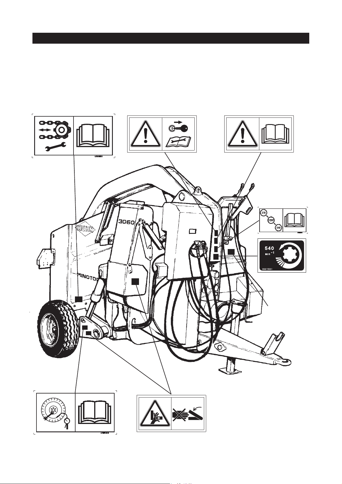
LABELS RELATING TO SAFETY
Adhesive labels have been placed on your machine as represented below . Their object is to contribute
to your safety and to that of others as well as to the correct operation of the machine. Read their
contents and check their location. Read the labels, as well as the instructions contained in the user
manual, with the operator of the machine.
Keep the labels clean and legible. Replace them when they become damaged.
12
Manufacturer’s
identification
plate
Page 13
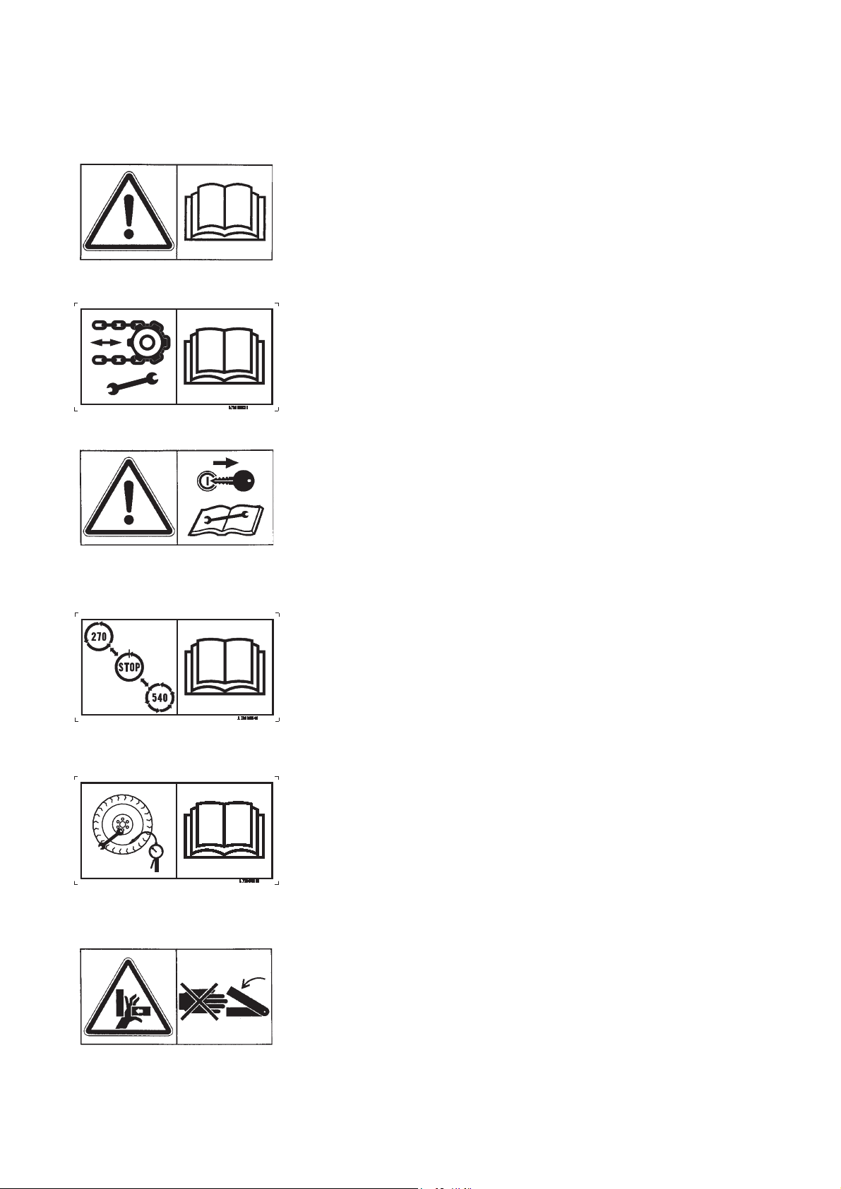
BEFORE COMMISSIONING THE MACHINE, READ THE
INSTRUCTION MANUAL AND THE RULES OF SAFETY
CHECK CHAIN TENSION REGULARL Y
BEFORE CARRYING OUT ANY MAINTENANCE ON THE
MACHINE, SWITCH OFF THE TRACTOR ENGINE, REMOVE
THE KEY FROM THE IGNITION AND WAIT UNTIL ALL MOVING
PARTS HAVE STOPPED
COMPULSORY.
STOP COMPLETELY TO CHANGE SPEED
CHECK REGULARL Y THE TYRES PRESSURE AND THAT
WHEEL NUTS ARE TIGHT
AL WA YS KEEP YOUR HAND AW AY FROM THE CRUSHING
AREA UNTIL ALL MOVING PARTS ARE A T A COMPLETE
STANDSTILL
13
Page 14

LIGHTING EQUIPMENT
MINOTOR 3050 - MINOTOR 3060
Lighting equipment is fitted as standard on the machines in accordance with current legislation.
The equipment includes:
- 1 LH tail light (A)
- 1 RH tail light (B)
- 2 reflective triangles (C)
C
A
C
B
14
Page 15

NOTES
15
Page 16
DESCRIPTION OF MOUNTED MINOTOR 3050
7
10
9
8
3
1
11
4
6
2
5
16
12
Page 17

1- BODY
111
ATHENOR 756011111
1
2- DELIVERY CHUTE
3- CONTROL UNIT
4- DRIVE UNIT
5- TURBINE
6- PROTECTIVE BOWL
7- ARM
8- GRAB
9- ARM RAM
10- GRAB RAM
11- CONVEYOR SPEED INDICATOR
12- THREE-POINT LINKAGE
111
17
Page 18
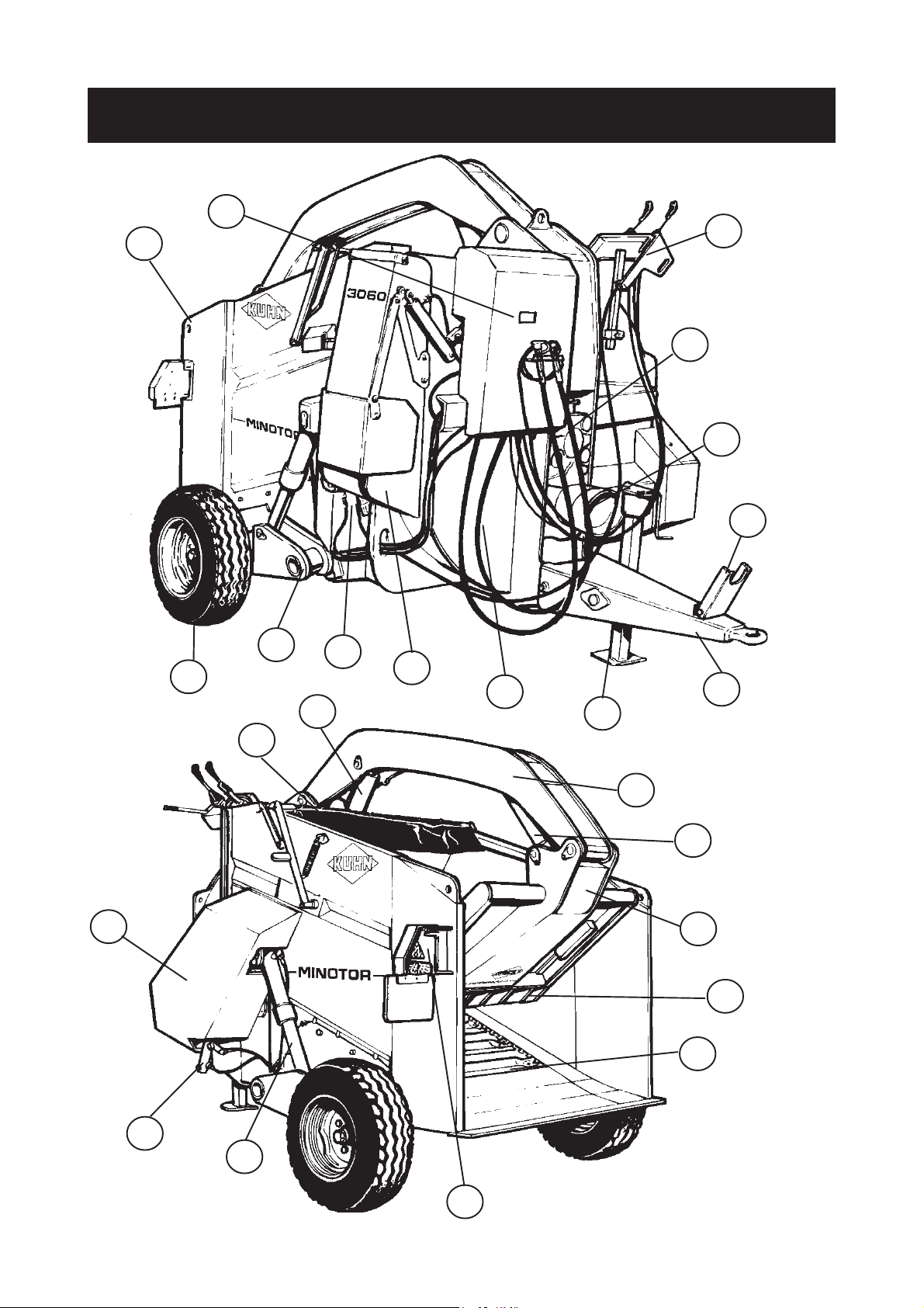
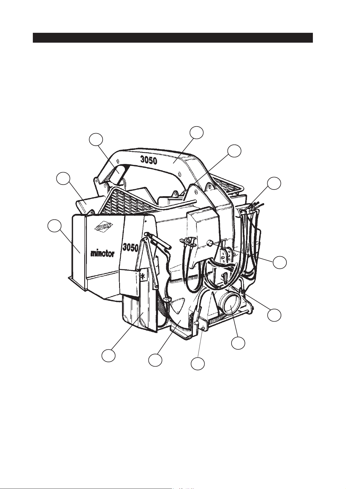
DESCRIPTION OF SEMI-MOUNTED MINOTOR 3050
AND BELT-DRIVEN MINOTOR 3060
24
1
7
8
12
9
22
3
2
16
13
4
10
6
5
21
14
17
15
20
19
23
18
11
18
Page 19

1 - BODY
2 - WHEEL
3 - AXLE
4 - DELIVERY CHUTE
5 - PARKING STAND
6 - TOW BAR
7 - CONTROL UNIT
8 - DRIVE UNIT
9 - DRIVE SHAFT SUPPORT
10 - TURBINE
11 - TAIL LIGHTS
12 - PROTECTIVE BOWL
13 - CONVEYOR REDUCTION GEAR
14 - ARM
15 - GRAB
16 - ARM RAM
17 - GRAB RAM
18 - BODY RAM
19 - CONVEYOR
20 - GRAB SCRAPER
21 - PROTECTIVE COVER ON BELT-DRIVEN MINOTOR 3060
22 - TRANSMISSION COVER ON BEL T -DRIVEN MINOTOR 3060
23 - CLUTCH RAM ON BEL T -DRIVEN MINOT OR 3060
24 - CONVEYOR SPEED INDICATOR
19
Page 20

TECHNICAL SPECIFICATIONS
0
MOUNTED MINOTOR 3050
Mounted silage loader / straw-blower / distributor with hydraulic axle.
Hydraulic drive on the loading device and distribution / spreading system.
REF. DEFINI TI O N MO UNTED MI NO T OR 305
A Overall width, chute c los ed m 1,94
A1 Overall width, chute opened m 2,67
B Overall length, machine on ground m 2,82
C Overall heig ht , m a c h ine o n groun d m 2,1 5
Max . height requirem ent
D* Machi ne on grou nd m 3,69
E Lateral overhang, chut e side m 1,15
F Lateral overhang, left -hand side m 0,78
G Inte rnal l en gt h of hopp er m 1,75
H Internal widt h of hopper m 1,35
I Internal d ep t h of hopper m 1, 0 5
J Mi nimum co upli ng heig ht m 0, 325
Maximal advisable silage loading
K
height, machine on ground
Spreading height
L* Min. m 0,52
Max. m 1,00
Max imum advised recovery at the
M
heap
Unlade n we ig ht in w ork i ng o rder kg 1525
Capacity m3 2,5
Payload kg 1275
Lifting power required kg 4500
M in. po wer req ui red hp/k w 50 - 36
Trac tor pressure required bar Min. 150 - Max. 180
Tract or output min. l/min 30 at required pressure
m3,5
m0,50
Tract or output max. l/min 60 at required pressure
* Depending on the tractor (take account of the lifting height)
OPTIONAL EQUIPMENT
- Anti-clogging kit for rectangular bales
- Category 2/3 lower link
20
Page 21

21
Page 22

TECHNICAL SPECIFICATIONS
SEMI-MOUNTED MINOTOR 3050, SEMI-MOUNTED MINOTOR 3050 WITH MIXING
HOPPER AND BELT-DRIVEN MINOTOR 3060
Semi-mounted silage loader , straw blower and distributor with hydraulic axle.
Hydraulic drive on the loading device and distribution/spreading system.
REF. DEFINITION 3050 TR 3050 TR TM 3060
A O verall wi dth, c h ut e cl osed m 2. 24 2.2 4 2.24
A1 Overall width, chut e opened m 3.38 3.38 3. 38
B Overall length, machi ne on ground m 3.75 4.36 3.75
C Ove ral l hei g ht, m ac h i ne on gro und m 2. 15 2.1 5 2.15
Ma x . he ig ht req ui rem e nt
D1* Machi ne on ground m 3.70 3.70 3.70
D2* Ax le at it s highest m 4.42 4.42 4.42
E L at era l overhang, chute si de m 1 . 15 1.1 5 1.15
F Latera l overhang, l eft -h a nd s i de m 1 . 08 1.0 8 1.08
G Internal l ength of hopper m 1.95 1.95 1.95
H Int ernal widt h of hopper m 1. 35 1.35 1.35
I Internal depth of hopper m 1. 40 1.40 1.40
J Mi ni m u m c o u pling hei gh t m 0. 235 0. 235 0.2 35
Maxim al advisable sil age loading
K
height, mac hine on ground
m 3.50 3.50 3.50
Spreading height
L* Min. m 0.55 0.55 0.55
Max. m 1.15 1.15 1.15
M Maximum advised recovery at t he heap m 0. 50 0.50 0.50
N Gauge width m 1.90 1.90 1.90
O Wheelbase m 2.85 2.85 2.85
Normal transportation height m 0.50 0.50 0.50
Unladen weight in working order kg 2220 2330 2260
Gross weight kg 3470 3580 3510
Capacity m3 3 3 3
Payload kg 1250 1250 1250
Tyres 10.75x 15 12 P R 10.75x 15 12 PR 10.75x15 12 PR
Tyre pressure bar 5.25 5.25 5, 25
Min. power required hp/kw 50 - 36 50 - 36 60 - 44
Trac t or pres s ure required bar 150 - 180 150 - 180 150 - 180
Tractor out p ut min. l/min 30 35 35
Tractor out p ut max. l/min 60 60 60
* Depending on tractor (take account of lifting height)
The optional mixing hopper and hydraulic unit are factory-fitted on the semi-mounted MINOTOR 3050
only .
Options - Free wheel homokinetic transmission - Heavy-duty wheels: 7.50x15 16 PR
- Anti-clogging kit for rectangular bales - Narrow wheels: 7.50x16 10 PR
- Electronic proportioning device on mixing hopper
22
Page 23

23
Page 24

DESCRIPTION OF THE CONTROLS
REMOTE CONTROL CABLES
MOUNTED / SEMI-MOUNTED MINOTOR 3050
A
E
RAISING / LOWERING THE MACHINE BODY (SEMI-MOUNTED 3050)
Lever A
The movements are made by pressing the switch on the control handle.
Push lever up to lower the body .
Pull lever down to raise the body .
D
F
B
C
RAISING / LOWERING THE DELIVERY CHUTE
Lever A
Push lever up to point the chute upwards.
Pull lever down to point the chute downwards.
CONVEYOR AND BEATER BAR OPERATION
Lever A
Turn lever to the lef t to run the conveyor and beater bar forwards.
Turn lever to the right to run the conveyor and beater bar in reverse.
24
Page 25

RAISING/LOWERING THE ARM
Lever B
Push the lever up to raise the arm.
Pull the lever down to lower the arm.
OPENING/CLOSING THE GRAB
Lever B
Turn lever to the left to open the grab out of the body.
Turn lever to the right to bring the grab in towards the body.
CHANGING THE TURBINE SPEED
Lever C
Push the lever for a turbine speed of 270 min-1. This speed is used for silage distribution.
Pull the lever for a turbine speed of 540 min-1. This speed is used for straw blowing.
ADJUSTING THE CONVEYOR SPEED
Switch D
Turn switch C to the left to increase the conveyor speed.
Turn switch C to the right to reduce the conveyor speed.
The conveyor speed increases on a scale from 0 to 10. The current speed is indicated on the front of
the machine.
ON MACHINES EQUIPPED WITH A MINERALS HOPPER
Switch F
Push the switch up to stop the hopper.
Push the switch down to run the hopper.
Switch E
Push the switch to the left to increase the auger speed.
Push the switch to the right to reduce the auger speed.
The auger speed increases on a scale from 0 to 10. The current speed is indicated on the front of the
machine.
The injection auger runs only when the mixing device runs.
25
Page 26
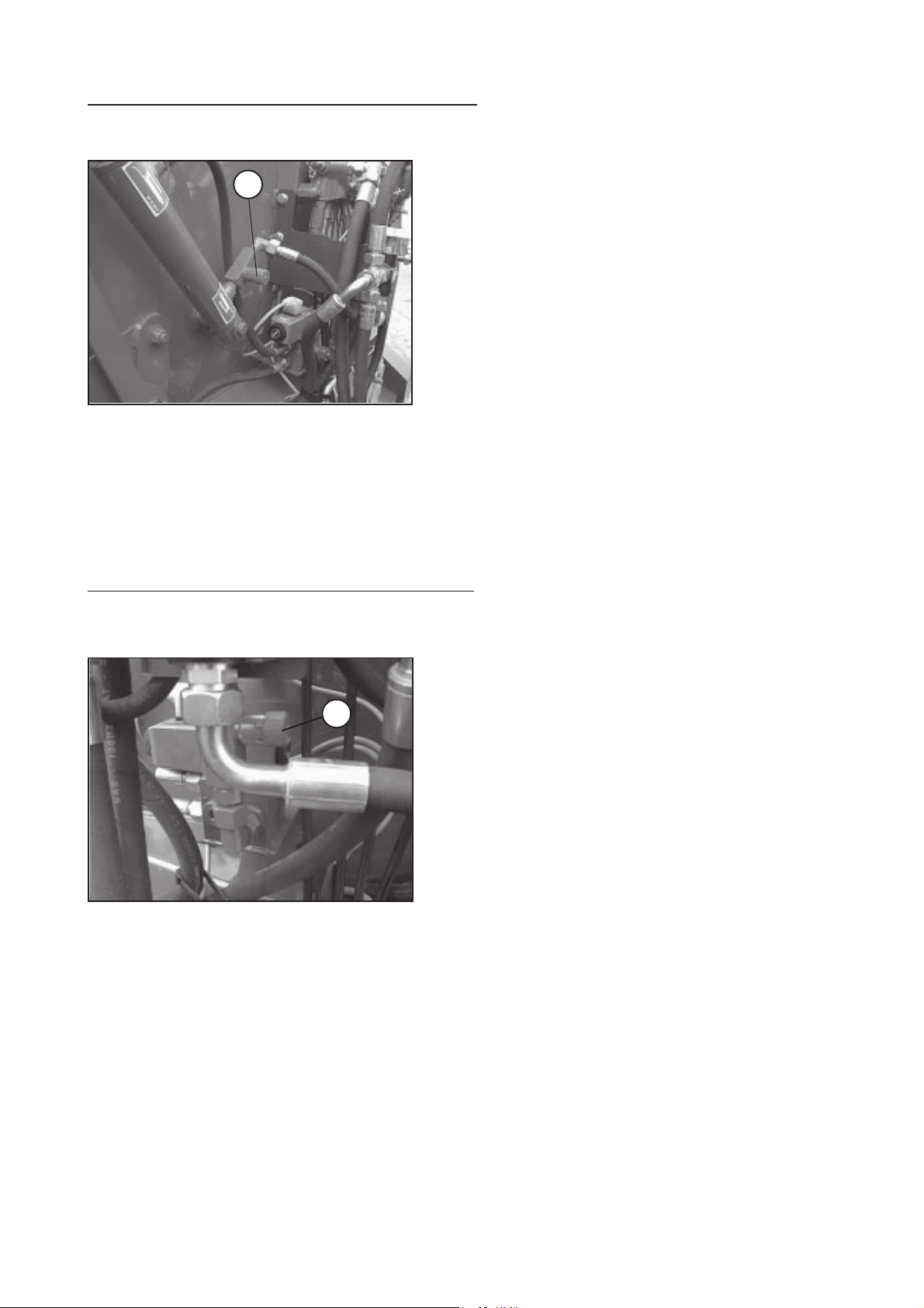
ADJUSTING THE DELIVERY CHUTE SPEED
The speed of chute movement is adjusted by a flow
limiter (1) on the ram.
1
T o adjust, unlock the limiter (Allen key n° 2) then select
the speed by turning the knobs.
Tighten the knob to reduce the speed of chute
movement.
Slacken the knob to increase the speed of chute
movement.
Beware! If chute movement is too slow, a blockage
may occur when the conveyor is running.
ADJUSTING THE BODY LOWERING SPEED
The body lowering speed is adjusted by a flow limiter
(2).
2
T o adjust, unlock the limiter (Allen key n° 2) then select
the speed by turning the knobs.
By tightening the knob, the body is lowered more slowly .
By slackening it, the body is lowered more quickly .
Beware! Lowering the body too quickly can prevent
correct chute operation.
26
Page 27

BELT-DRIVEN MINOTOR 3060
A
D
ENGAGING AND DISENGAGING THE BEATER BAR
Lever A
Pull lever down to engage the beater bar .
Push lever up to disengage the beater bar.
RAISING / LOWERING THE MACHINE BODY
E
B
C
Lever A
The movements are made by pressing the switch on the control handle.
Turn lever to the left to lower the body.
Turn lever to the right to raise the body.
RAISING / LOWERING THE DELIVERY CHUTE
Lever A
Turn lever to the left to point the chute upwards.
Turn lever to the right to point the chute downwards.
27
Page 28

RAISING / LOWERING THE ARM
Lever B
Push the lever up to raise the arm.
Pull the lever down to lower the arm.
OPENING / CLOSING THE GRAB
Lever B
Turn lever B to the left to open the grab out of the body.
Turn lever B to the right to bring the grab in towards the body.
CHANGING THE TURBINE SPEED
Lever C
Push the lever for a turbine speed of 270 min-1. This speed is used for silage distribution.
Pull the lever for a turbine speed of 540 min-1. This speed is used for straw blowing.
CONVEYOR OPERATION
Switch D
Turn switch to the lef t to run the conveyor forwards, only if the beater bar is engaged.
Turn switch to the right to run the conveyor in reverse.
ADJUSTING THE CONVEYOR SPEED
Switch E
Turn switch to the lef t to increase the conveyor speed.
Turn switch to the right to reduce the conveyor speed.
The conveyor speed increases on a scale from 0 to 10. The current speed is indicated on the front of
the machine.
28
Page 29

ADJUSTING THE DELIVERY CHUTE SPEED
1
The speed of chute movement is adjusted by a flow
limiter (1) on the ram. To adjust, unlock the limiter
(Allen key n° 2) then select the speed by turning the
knobs. T ighten the knob to reduce the speed of chute
movement. Slacken the knob to increase the speed
of chute movement.
Beware! If chute movement is too slow, a blockage
may occur when the conveyor is running.
ADJUSTING THE BODY LOWERING SPEED
The body lowering speed is adjusted by a flow limiter
(2).
2
To adjust, unlock the limiter (Allen key n° 2) then select
the speed by turning the knobs.
By tightening the knob, the body is lowered more slowly .
By slackening it, the body is lowered more quickly .
Beware! Lowering the body too quickly can prevent
correct chute operation.
ADJUSTING THE ENGAGEMENT/DISENGAGEMENT RAM SPEED
The ram speed is adjusted by a flow limiter (1) located
at the entrance to the small chamber.
To adjust, unlock the limiter (Allen key n° 2) then select
1
the speed by turning the knob.
By tightening the knob, the ram moves more slowly and
by slackening it, it is moved more quickly .
Beware! Setting the ram speed too high can lead to
excessive vibration.
29
Page 30

STARTING UP
HITCHING
Before hitching the machine, make sure that there is sufficient ballast on the
front axle of the tractor.
Ballast should be added to the special supports according to the tractor
manufacturer’s instructions. The front axle load must be not be less than
20% of the unladen tractor weight.
Semi-mounted Machine
For road transport, hitch the machine on to the tractor eye bolt – cf. Fig. 1
. Using the parking stand, set the towing eye to the same height as the eye bolt.
. Back up the tractor, then lift the parking stand to hitch the machine to the tractor.
. Lock the hitch with the special device.
For use on the farm, hitch the machine to the tractor lifting system – cf. Fig. 2
. Fit the drawbar (1) onto the lifting arms.
. Lock the drawbar (1) with 10 mm clips (2) (not supplied).
. Back up the tractor until the towing eye is lined up with the pin hole in the drawbar.
. Insert a 150 mm long, 28 mm dia. retaining pin (not supplied).
. Once the machine is coupled up, stabilise the drawbar laterally with the special devices provided
(bar, chain, chocks, etc.).
Fig. 1
Switch off the tractor engine before carrying out any operations between the
machine and the tractor.
30
Fig. 2
Page 31

Mounted Machine
The Minotor can be attached to all tractors with a standardised three-point lift. It is equipped as
standard with a category 2 linkage, complete with a 28 mm dia. trunnion drawbar, 825 mm long
between the ball joints.
- Position the drawbar on the lifting arms.
- Secure the drawbar with the special pins (photo 1).
1
- With the machine firmly resting on the ground, back up the tractor until the bar locks into the machine
linkage. The lock should have returned to its initial position (photo 2).
31
2
Page 32

- When the tractor engine has been coupled up, adjust the upper link length so that the machine is
resting firmly on the ground (photo 3).
- Insert the upper link pin (photo 3) and fit the locking pin.
3
- Once the machine is hitched to the tractor, stabilise the three-point linkage laterally with the special
device (bars, chains, shims, etc.) (photo 4).
32
4
Page 33

ADJUSTING THE POSITION OF THE CONTROLS
Remote control cables
There are two types of control unit mounting:
. Mounting the unit on the machine.
This is designed for mounting the control unit when the machine is uncoupled from the tractor .
. Mounting the unit on the tractor
The machine is supplied with a control unit bracket for self-assembly. It is best fitted on the
lower crossbar in the rear opening of the cab (see photos below).
Make sure that the remote control cables cannot be damaged by tractor and
machine manoeuvres.
Electric control unit
The user may choose the location for the unit.
33
Page 34

TRANSMISSION
Working Parts (PTO and universal drive shafts)
Carefully read the instructions supplied with the transmission.
1. Only use universal drive shafts supplied with the machine or recommended by the manufacturer .
2. The PTO and universal drive shaft guards must always be fitted and in good condition.
3. Make sure that there is correct tube overlap on the universal drive shafts, both in the working
position and the transport position. Adjust the length of the tubes if necessary.
4. Before connecting or disconnecting a universal drive shaft, disengage the PTO, switch off the
engine and remove the key from the ignition.
5. Always make sure that the universal drive shafts are properly fitted and secured.
6. Make sure that the universal drive shaft guards are prevented from rotating by the special chains.
7. Before engaging the PTO, make sure that the speed setting and direction of rotation comply with
the manufacturer’s instructions.
8. Before engaging the PTO, make sure that there are no persons or animals near the machine.
9. Never engage the PTO with the tractor engine switched off.
10. Disengage the PTO whenever the universal drive shaft angle limits indicated by the manufacturer
are in danger of being exceeded.
11. Beware! After disengaging the PTO, moving parts continue to rotate for a few seconds. Keep
away until they have stopped.
12. On unhitching the machine, rest the universal drive shafts on the special supports.
13. When the universal drive shaft has been disconnected from the tractor PTO, refit the protective
cap.
14. Any damaged PTO and universal drive shaft guards must be replaced immediately.
15. Beware! Only use the machine with a PTO speed of 540 min
-1
.
16. Any action on the lift function may damage the transmission.
17. Check that the overload clutch is working properly. After a period of inactivity, disassemble and
clean the clutch (see the transmission instructions supplied with the machine).
34
Page 35

UNIVERSAL DRIVE
- At maximum extension, there must be a tube overlap of A = 330 mm (Fig. 4).
Fig. 4 Fig. 5
- At maximum overlap (with the drive shaft compressed), there must be a safety gap of B = 20 mm to
prevent the tubes striking the jaws (Fig. 4).
- If the above conditions are not met, shorten the guards (1) and the tubes (2) by the same length (X)
(Fig. 5).
- Round off and clean the tubes and grease the inside of the outer tube.
- Always make sure that the universal drive shafts are properly fitted and secured.
- Any damaged PTO and universal drive shaft guards must be replaced immediately.
Make sure that the drive guards are properly fitted and prevented from rotating
by the special chains. Replace any damaged guards immediately.
Consult the operating and maintenance instructions enclosed with the drive
shaft.
CONNECTIONS
Hydraulic
(Machines not equipped with an auxiliary unit)
The machine requires a double-acting hydraulic distributor with an independent lift function. The
machine’s hydraulic circuit operates at a maximum pressure of 180 bar.
The pressure hose is equipped with a female push-pull coupler (ISO 7241).
The return hose is equipped with a female push-pull coupler (ISO 7241).
Connect the distributor supply hoses to the tractor. The pressure hose (P) is identified by a white
arrow on a red background, with the arrow pointing away from the tractor towards the distributor. The
return hose (T) is identified by a white arrow on a blue background, with the arrow pointing away from
the distributor towards the tractor.
35
Page 36

The hydraulic connection to the tractor may be made in one of three ways:
1. Single-acting distributor pressure and direct return to tank.
2. Double-acting distributor pressure and return to second orifice of the same distributor (beware
of direction of oil flow)
3. Pressure on line to be followed from tractor distributor and return to tank.
Connect the hoses. Make sure that the hoses cannot catch while in operation.
If the machine distributor is connected to the original tractor distributor , activate the relevant handle on
the tractor distributor to pressurise the hydraulic circuit (beware of direction of oil flow).
LIGHTING
Keep all lighting clean and in good working order. Rep air them immediately.
Before taking out onto public roads, check that all lighting is in good working
order.
Plug the lighting equipment into the standardised 7-pin socket at the rear of the tractor .
CONTROL HARNESS SUPPLY
- Machine with remote control cables.
- The electric power cable (2) is not supplied mounted.
- Connect this cable to the + and - terminals on your tractor battery
1
2
If you use a second tractor, ask for a second power cable (2) – part n° A7040064.
For a constant, even power supply to the machine, the electric power cable must be connected to the
battery. The power cable socket (2) is best fitted onto the lower crossbar in the rear opening of the
cab.
4
(brown wire to + and blue wire to -).
- Then connect the socket (1) to the power cable (2) to activate
the controls. The power cable is equipped with a 15 Amp fuse
(4) – part n° A7040915.
When mounting the power cable on the tractor, pay attention to the routing of the wire. Beware of
shearing, burning on the exhaust pipe, etc.
36
Page 37

ADJUSTING THE DELIVERY CHUTE
- The MINOTOR delivery chute can now be set to two positions:
1. A wide opening for the distribution of fibrous products
(long hay , round bales of haylage, etc.) (photo 1).
2. A narrow opening for the distribution of fine-cut
products and straw blowing (photo 2).
1
The chute opening can therefore be selected according
to the products to be distributed. This is done using the
elbowed connecting rod when the chute is slightly open.
PRELIMINARY CHECKS
. Hydraulic and electrical connections. Make sure that the pressure and return hoses are
properly connected
. Machine securely hitched to tractor
. No loose components
. Hydraulic hoses
. Chain tension.
. Choice of turbine speed.
. Drive shaft length.
. Oil level in turbine drive unit.
. Oil level in conveyor drive unit.
2
. Oil tank level and condition of oil filter (on optional auxiliary unit).
37
Page 38

NO-LOAD TESTS
Do not stand in the working area of the machine.
Before starting up, the user must familiarise himself with the machine’s
operating controls and their respective functions. Once work has begun, it
will be too late.
Before starting up the machine, check around the machine (beware of
children!). Make sure that you have sufficient visibility .
Keep people and animals away from the danger area of the machine.
In the case of a “free wheel” PTO shaft, the turbine may continue to run for
around two minutes after the PTO has come to a complete standstill.
- Test each control in both directions: arm, grab, beater bars, turbine, chute, axle and cover.
- Check the hydraulic circuit for leaks.
- Test the lighting and signalling system (side lights, brake light s and turn-signal indicators).
UNHITCHING
- Before unhitching the machine, bring the grab inside the body and lower the arm completely (ram
rods fully retracted).
- Lay the machine on the ground so that it is stable (adjust the parking stand if necessary).
- Before unhitching the machine, switch off the tractor engine and remove the key from the ignition.
- Uncouple the hydraulic pressure and return hoses and the electrical connections.
- Apply the machine’s parking brake.
- Remove the hitch safety cable.
- Unhitch the machine.
38
Page 39

MACHINE OPERATION
Read carefully before starting up the machine.
The machine must be used by one person only.
Before starting up the machine and beginning work, check around the machine
(beware of children!). Make sure that you have sufficient visibility.
Keep people away from the danger area of the machine.
Beware! When operating the loading components (arm, grab, machine body)
and mixing components (cover), make sure that there can be no accidental
contact with a power line.
Never stand behind the machine during product mixing.
Never stand beside the distribution chute while the machine is in operation.
Before starting up, check that the machine is in good condition, the tension of
the chains is correct, the components are properly greased and the screws
are tight.
Before commencing any manoeuvres in reverse gear or operating the loading
gear, sound the horn twice.
1. SILAGE LOADING
Approaching the Silo (Fig. 1 showing an ALTOR 7560)
- Hitch the machine to the tractor (see “Starting Up” section).
- Raise the arm and grab for good visibility .
- Lower the machine as closely as possible to the ground in order to secure it to the silo with its heel
plate.
- Reverse the machine into the silo. Do not try to back your way into the silo by force.
- In the case of a clamp silo, position the machine slightly aslant in order to load as closely as possible
to the wall.
39
Page 40

Loading (Fig. 2 showing an ALTOR 7560)
1. Lower the machine. It should rest on its ground plate at the front and on its shoe at the rear.
2. Start up the hydraulic circuit on the tractor and bring up to nominal speed.
3. From the cab or platform, position the grab so as to take around 50 cm of product. Make sure that
the cutting angle of the grab is correct. Never attempt to cut into the silo with the grab flat.
4. Always begin cutting the silo from the top, never from the bottom (risk of collapse).
5. Swing the grab gently back and forth while lowering the arm slowly. This will bring the grab down
evenly without upsetting the silo.
6. Once the grab is lowered, bring it back inside the machine body to fill it properly. Raise the arm
with the grab closed and repeat operations 3, 4, 5 and 6 until the machine body is full. Do not
overpack the product.
The kinematics of the arm/grab assembly provides a vertical cutting face and good pick-up from the
floor of the silo.
When loading is complete, bring the grab into the rear door position without overpacking the product.
2. LOADING BALES
Approaching the Bale
- Hitch the machine to the tractor (see “Starting Up”
section).
- Raise the arm and grab for good visibility.
- Remove the twine before loading the bale.
The operator must be standing outside the machine
with the engine off.
- Back the machine up to the bale and position the
machine heel plate as close as possible to the
ground (Fig. 3).
- Position the bale in the direction that it will be unrolled.
- More even distribution and straw blowing is obtained
in this way (Fig. 4).
Loading the bale
- Envelop the bale by fully extending the grab and
bringing down the arm until it comes into contact
with the bale.
- Maintain pressure on the arm while backing up slowly .
- When the bale has entered the machine body,
complete loading by combining grab and arm
movements (Fig. 4).
- For even straw spreading, the bale must remain in
contact with the beater bar .
FIG. 3
FIG. 4
40
Page 41

3. TRANSPORT
It is strictly prohibited to use the machine to carry persons or animals whilst in
operation or transit.
Observe the maximum vehicle gauge for transport on public roads.
Before entering public roads, make sure that all guards and signalling devices
required by law are fitted and working properly .
Before entering public roads, put the machine into the transport position in
accordance with the manufacturer’s instructions (see Technical
Specifications).
You should always adapt your speed and driving to the track, road or land.
Avoid sudden changes of direction in all circumstances.
Steering accuracy, tractor adhesion, roadholding and effective braking are
affected by factors such as the weight of the towed machine, ballasting of the
front axles and state of the land or road.
Disengage the PTO and wait until the fan comes to a complete standstill (up
to 2 mins.).
4. DISTRIBUTION
MOUNTED AND SEMI-MOUNTED MINOTOR 3050 / MINOTOR 3060
Before getting down from the tractor or before any operations on the machine,
lay the machine on the ground, switch off the engine, remove the key from the
ignition and wait until all moving parts are at a standstill.
Always start up the PTO before running the conveyor/beater bar and always
stop the conveyor/beater bar before disengaging the PTO. Failure to comply
with this procedure will result in a blockage.
Always start the beater bar with the conveyor speed control set to zero.
- Set the fan speed according to the product to be distributed:
. 270 min-1 for silage
. 540 min-1 for straw
- Adjust the tractor engine speed according to the required distribution distance.
41
Page 42

Silage distribution
- The turbine should be set to 270 min
-1
.
- Engage the tractor PTO.
- Start up the tractor hydraulics and bring up to nominal speed.
- Position the chute so that the silage is correctly channelled towards the floor or a manger.
- Release the grab slightly to ensure that the product is not packed too tightly .
- Product output is adjusted by:
. the tractor engine speed (which determines the hydraulic output and PTO speed),
. the forward speed of the tractor,
. the forward speed of the conveyor (to adjust, refer to “Description of Controls”).
- To distribute silage, start up the beater bar and conveyor (refer to “Description of Controls”).
- To stop distribution for a moment (posts, various obstacles, etc.), stop the beater bar and conveyor
rotation.
- At regular intervals, bring the silage on to the conveyor by pulling in the grab.
- When distribution is over, bring in the arm and grab completely . Close the delivery chute, disengage
the tractor PTO and switch off the engine.
Should the beater bar jam, switch the beater bar and conveyor into reverse in short bursts to free. It
may occasionally be necessary to hold the switch for a few seconds to shift back the mass of silage
inside the body .
Beware of the direction of rotation of the beater bar and conveyor .
A loaded machine running too long in reverse may be seriously damaged.
Never attempt to clear the product by hand or with a tool (fork, etc.) while the
machine is running.
Never climb on the machine or work inside the body while the machine is
running.
Beware! Blades, conveyors and other parts in contact with the product may
wear out quickly .
Any part which, through wear , is in danger of coming away and getting mixed
up with the feed must be replaced immediately .
42
Page 43

Straw bedding
-1
- The fan should be set to 540 min
.
- Engage the tractor PTO.
- Start up the tractor hydraulics and bring up to nominal speed.
- Position the chute so that the straw is projected where required.
- For even spreading, the bale must remain in permanent contact with the beater bar without over-
jamming it with the claw. Raise the machine slightly at the rear to prevent the bale from being
projected back by the rotation of the beater bar .
- The product output is adjusted by:
. the tractor engine speed (which determines the hydraulic output and the speed of rotation of
the PTO),
. the forward speed of the tractor,
. the forward speed of the conveyor (to adjust, refer to “Description of Controls”).
- To distribute the product, start up the beater bar and conveyor (refer to “Description of Controls”).
- T o stop distribution instantaneously (posts, various obst acles, etc.), stop the beater bar and conveyor
rotation.
- At regular intervals, bring the bale into contact with the beater bar by pulling in the grab.
In the event of a beater bar blockage, switch the beater bar into reverse in short bursts to free.
Beware of the direction of rotation of the beater bar and conveyor .
A loaded machine running too long in reverse may be seriously damaged.
Never attempt to clear the product by hand or with a tool (fork, etc.) while the
machine is running.
Never climb on the machine or work inside the body while the machine is
running.
Beware! Blades, conveyors and other parts in contact with the product may
wear out quickly .
Any part which, through wear , is in danger of coming away and getting mixed
up with the feed must be replaced immediately.
43
Page 44

Note: Should the turbine or beater bar become jammed, use the hook mounted inside the housing
on the left-hand side of the machine (see photo below) to pull out the jammed product at
the distribution chute or beater bar , then use a lever to ensure that the turbine can rot ate
freely.
44
Page 45

BELT-DRIVEN MINOTOR 3060
Always start the PTO before engaging the belt drive and always disengage
the belt drive before stopping the PTO. Failure to comply with this procedure
will result in a blockage.
Always start the beater bar with the conveyor speed set to zero.
Always check that the fan is set to 270 min
-1
for silage and haylage and 540
min-1 for straw.
When distributing haylage, it is preferable for the bale to be loaded in
the direction that it will be unrolled.
- The MINOTOR 3060 is equipped with a limit of travel sensor for the belt clutch ram (see photo 3).
This sensor is located under the large side casing just behind the tension spring. It is tripped when
the clutch ram is fully engaged. At this point, the conveyor can be started up in forward motion.
There are several advantages to this design:
- The conveyor only runs forwards when the belt is
fully engaged
⇒⇒
⇒ no risk of beater bar blockage.
⇒⇒
- The conveyor can run in reverse, however, even if
the sensor has not tripped (the beater bar does not
rotate)
⇒⇒
⇒ the body can be safely emptied out of the
⇒⇒
back.
- The conveyor control switch has a latched position
in forward operation which, together with the limit of
travel sensor, makes it possible to use just the lefthand beater bar lever
3
can therefore be left at any time in the latched position
⇒⇒
⇒ the conveyor control switch
⇒⇒
in order to start up the conveyor at the same time as
the beater bar, as on the Minotor 3050 TR with a
hydraulic beater bar .
- The protective cover is only used at the end of distribution. The cover must not be unfolded, therefore,
when the product to be distributed (grass silage, round bales of hay, haylage or straw) is too
voluminous (a round bale must be able to rotate freely).
- In the course of distribution, the machine body may be raised or lowered to:
- keep round bales up against the beater bar when the product is easy (hay, straw, fine-cut
haylage, etc.);
- facilitate bale rotation with tougher products. An approximate height of 50 cm between the
sill wear plate and the ground is recommended (bales of rough-cut haylage, etc.).
45
Page 46

ADJUSTING THE LIMIT OF TRAVEL SENSOR
CLUTCH CONNECTING ROD
A5250636
POSITION SWITCH ADJUSTMENT
STOP
M4X40 HEX SOCKET HD SCREW
POSITION SWITCH
A7040714
- In the engaged position: 2 mm
clearance between stop and switch
in “full in” position.
M4 NUT
USING A BELT-DRIVEN BEATER BAR
1. Check that there is no pressure on the silage or bale against the beater bar. If this is the case,
release the grab slightly from the bale.
2. A height of approximately 50 cm between the sill wear plate and the ground is recommended.
3). Set the delivery chute according to the product to be distributed (refer to “Starting Up”).
4. Select the turbine speed.
5. Start the PTO.
6. Check that the conveyor forward speed is set to zero.
7. Engage the beater bar .
8. Latch the conveyor switch in forward motion (see previous page).
9. Select the conveyor speed (depending on the tractor output and the nature of the bale).
10. In the course of distribution, the grab can be moved slightly forward to keep the product in contact
with the beater bar .
1 1. Unfold the cover at the end of distribution if product is being projected out of the machine.
12. At the end of distribution, disengage the beater bar, bring the arm and grab fully in, stop the PTO,
close the chute and switch off the engine.
46
Page 47

OPTIONS
t
The optional equipment listed in the table below is available for the machines.
OPTIONS 3050 P 3050 TR 3050 TR / TM 3060 Be l
Free wheel wide angle PTO shaft
Narrow wheels 7.50 x 16 10 PR
Heavy-duty wheels 7.50 x 15 16 PR
Auxiliary hydra u lic unit
Anti-clogging kit for rectangular bales
Mixing hopper
Electronic proportioning device
XX X
XX X
XX X
XX X
XX
X
X
The optional mixing hopper and auxiliary hydraulic unit are factory-mounted only .
Before fitting any optional item of equipment to a machine, observe these few rules :
- Check that the equipment received is the equipment actually ordered.
- Carefully read the assembly and operating instructions supplied with the option.
Beware!
WHEN CLEARING A BLOCKAGE OR REPLACING A WORKING PART,
WEAR PROTECTIVE GLOVES AND ONLY USE APPROPRIATE TOOLS.
To fit the options, you will need to use a variety of handling equipment and
tools. Refer to the safety instructions for such equipment before use.
The machine must be unhitched from the tractor before assembling an option.
Before assembling an optional device with the machine or one of the machine’s
loading components in the raised position, prop up the machine or the
component with an appropriate support.
If lifting gear (block and tackle, elevator, etc.) is used to handle the machine,
only use the specially provided lifting hooks shown by a pictogram.
47
Page 48

FREE WHEEL HOMOKINETIC TRANSMISSION
PTO shaft assembly providing a greater angle of deflection and free rotation of the turbine.
Please read the manual supplied with the transmission carefully .
MIXING HOPPER
ELECTRONIC PROPORTIONING DEVICE
Mineral distributor which may be equipped with a proportioning unit.
Please read the manuals supplied with the hopper and proportioning device
carefully.
48
Page 49

TYRES
Before carrying out any operations on the tyres, make sure that the trailer is
perfectly stable and cannot move accidentally (fit chocks).
Wheels and tyres should only be fitted, removed and repaired by persons with
the necessary knowledge and the appropriate statutory tools to do the job.
Check tyre pressure regularly. Observe the pressure levels recommended
by the manufacturer.
Check regularly that all wheel nuts are tight.
TYRES AVAILABLE FOR THE MINOTOR 3050 TR AND TR/TM AND 3060 WITH BELT
DRIVE
Standard tyres: 10x75x15 12 PR
Pressure: 5.25 bar
Max. load per tyre: 2030 kg
Narrow tyres: 7.50x16 10 PR
Pressure: 5.5 bar
Max. load per tyre: 1600 kg
Heavy duty tyres: 7.50x15 16 PR
Pressure: 9.5 bar
Max. load per tyre: 2220 kg
49
Page 50

ANTI-CLOGGING KIT FOR RECTANGULAR BALES
Device regulating the input of straw into the turbine.
DESCRIPTION
- Three anti-clogging regulators
- Six M10 washers
- Six HM 10 x 20 screws
FITTING
- The three regulators (A) are mounted inside the machine body, just above the beater bar . Riveted
nuts are already in place to take the M10 screws. Tighten the screws.
50
Page 51

HYDRAULIC UNIT
Hydraulic unit designed to provide sufficient hydraulic power to ensure correct machine operation.
DESCRIPTION
- Auxiliary hydraulic unit.
- Driven by tractor PTO.
- 38 cm³ pump
- 37 litre tank with filter and level gauge
- Circuit protected by valve calibrated to 180 bar.
- Recommended oil: Shell HYDRAU PW (ISO 46 type).
OPERATION
- Before starting up a machine equipped with a hydraulic unit, check the oil level in the tank.
- T o avoid environmental contamination, it is forbidden to throw away or dump any type of oil, grease
or filter . Hand them over to specialist firms.
- Connect the transmission to the tractor PTO and to the pump step-up gear drive shaft. Lock on.
- Beware! The machine must be driven at the nominal PTO speed of 540 min-1.
- Never couple the universal drive shaft to the 1000 min-1 PTO on the tractor.
- Start up the tractor . Gradually engage the PT O. The pump rotates. T ry the various machine controls.
Check the pump flanges and the various hydraulic connections on the unit for leaks.
- With the aid of the speed control lever, the unit may be used in three ways:
. at neutral, therefore without running the turbine, for all loading operations;
. with a turbine speed of 270 min
. with a turbine speed of 540 min-1.
-1
51
Page 52

MAINTENANCE
- Comply with the safety instructions relating to machine maintenance.
- Periodically check the oil level in the tank (level gauge - ref. 9).
The oil level should not be below the top 1/3 of the gauge.
- Change the hydraulic oil after the first 500 hours of work.
We recommend an ISO 46-grade hydraulic oil (e.g. Shell HYDRAU PW).
- Thereafter, the oil must be changed after every 2000 hours of work (drain plug - ref. 10; 22 mm
wrench and filler cap - ref. 7).
- Tank capacity: 37 litres.
- Change the filter element after 50 hours and then every 500 hours (ref. 6).
Part number: A4079006.
- Unscrew the cap (5).
- Take hold of the filter handle and extract the filter + bowl assembly. To remove the filter, turn
90° anticlockwise and extract it from its cartridge. Clean the bowl.
- Insert a new filter and lock into position by turning it 90° clockwise.
- Screw in the plug and make sure that the seal is correctly repositioned to prevent leaks.
52
Page 53

53
Page 54

MAINTENANCE
BEFORE CARRYING OUT ANY MAINTENANCE, SERVICING OR REPAIR
WORK OR WHEN INVESTIGATING THE CAUSE OF A FAILURE OR
MALFUNCTION, YOU MUST SWITCH OFF THE ENGINE, LA Y THE MACHINE
DOWN, REMOVE THE IGNITION KEY AND WAIT FOR THE MOVING P ARTS
TO COME TO A COMPLETE STANDSTILL.
Before proceeding with any maintenance work on a machine in the raised
position, prop up the machine with an appropriate support.
When replacing a working part or operating on sectional beater bars, wear
protective gloves and only use appropriate tools.
Beware! Never pass between the beater bars and regulators to access the
turbine.
To avoid environmental contamination, it is forbidden to throw away or dump
any type of oil, grease or filter. Hand them over to collection firms.
Before carrying out any operations on the electrical circuit, disconnect the
power source (tractor charging circuit or battery).
Any protective devices liable to wear should be checked regularly. Replace
them immediately if they are damaged.
Spare parts must comply with the standards and specifications laid down by
the manufacturer. Only use Kuhn spare parts.
Before carrying out any electrical welding work on the tractor or towed machine,
disconnect the cables from the alternator and battery .
Check the tightness of screws and nuts regularly. Tighten up if necessary.
SPECIAL MAINTENANCE FOR THE MINOTOR 3060
- General maintenance on the MINOTOR 3060 is identical to the MINOTOR 3050.
- The belt drive does not require any particular attention, except at the greasing points.
- Never upset the tension spring adjustment as this could cause belt damage.
- Do not clean the belts with a high-pressure jet.
54
Page 55

CONVEYOR CHAIN TENSION
To be checked every 100 hours. If the sag exceeds 150 mm, tighten up the chains.
To tighten the chains:
- Open the door (1) with the two levers (2) (Photo 1).
- Loosen the check nuts (3) with a 30 mm wrench (Photo 2).
- Tighten the assembly with the nuts (4) using a 30 mm wrench.
- Tighten the check nuts (3) with a 30 mm wrench.
- Close the door.
- Never fully tighten the chains. Always leave at least 50 mm of sag (Figure 1).
Figure 1
1
2
1
3
4
2
55
Page 56

y
MAINTENANCE SCHEDULE
Beware! The schedule indicated below has been calculated for normal conditions of use. If the working
conditions prove more difficult, grease more often.
Every
After Every Every After Every Every 2000
After 50 50 100 500 500 1500 hours
1 hour hours hours hours hours hours hours or ever
Tighten wheel bolts (100 N.m) X X
Tighten drawbar eyebolts X X
Grease arm joint: X X
Grease grab joint: X X
Grease axle joint: X X
Grease chute rams: X X
Grease arm ram: X X
Grease grab r am: X X
year
Grease axle rams: X X
Grease beater bar bearing: X X
Grease clutch ram (3060) : X X
Grease drive shaft bearing (3060): X X
Grease clutch rod (3060): X X
Gr ease conveyor (2 outside, 2 inside machine) X X
Grease parki ng stand X X
Change conveyor reduction gear oil: X X
Change gearbox oil: X X
Change hydraulic unit oil: X X
Change hydraulic unit filter cartr i dge X X
Check conveyor chain tension X X
Check conveyor reduc tion gear oil level X X
Check gearbox oil level X X
PTO shaft : For the maintenance period, refer to the instructions supplied with the PTO shaft.
56
Page 57
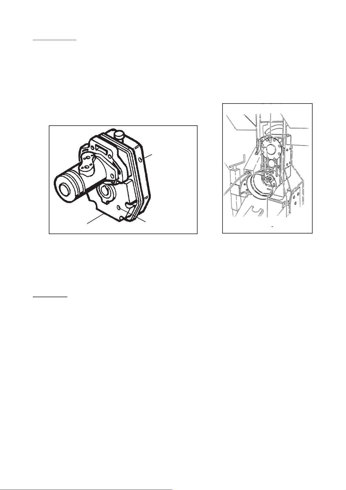
OIL CHANGE
The oil needs to be changed in:
- the conveyor reduction gear unit, quantity 0.5 litres (Figure 1)
- the gearbox, quantity 5 litres (Figure 2).
Change the oil after the first 50 hours of work, then every 1500 hours thereafter .
Check the oil level regularly to prevent abnormal damage to the units.
Fill
Remplissage
Fill plug
Vidange
Drain
Figure 1
Level
Niveau
Drain plug
Fig. 1
Level gauge
plug
Remember! The oil in the optional hydraulic unit also needs to be changed (refer to the OPTIONS
section).
STORAGE
- If the machine is not to be used for a long period, prepare it for storage:
- Clean the body (inside, outside and underside), arm, grab and cover with a jet spray . Remove any
product build-up. If necessary, repaint any surface in danger of rusting. Grease the underbody.
- When using a pressure washer, beware of sensitive components (ram joint s, electrical connections,
belt , etc...).
- Grease the ram rods to protect them from moisture and dust.
- Grease the drive chains.
- Clean all greasing points and joints. Grease.
- Wherever possible, store your machine in a sheltered area, on blocks, to isolate it from ground
damp.
- Check tyre pressure and wheel bolt tightness.
57
Page 58

TROUBLESHOOTING GUIDE
PROBLEMS P OSSIBLE CAUSES W HAT TO DO
Loading difficulties
Insufficient grab power Hy draulic problem . Check that the hy draulic connec tion
between the tractor and the mac hine
is correct (press ure and return).
. As k y our dealer to chec k the hydraulic
pres sure (180 bars) and the pump flow
(30 l/m in.). The return press ure mus t
be at leas t 8 bar at the nom inal tractor
engine speed.
Distribution difficulties
Im poss ible to dis tribute: Turbine jam m ed . S witch off the tractor engine and
. Turbine fails to rotate, overload disengage the trac tor P TO (see the
clutch slipping Safety Precautions sec tion).
. Check that product hasn’t built up in the
turbine. If this is the cas e, use the hook
m ounted ins ide the housing on the lefthand side of the m achine to pull out the
jamm ed product at the dis tribution chute
or beater bar, then use a lever to ensure
that the turbine c an rotate freely . Onc e
released, run the turbine em pty for a few
sec onds until it reac hes its normal
working speed.
The turbine rotates, the convey or Conveyor set to 0 . Set convey or s peed to appropriate m ark
and beater bar m ove forw ards (s ee Des cription of Controls s ection).
but no product appears
Beater bar jam m ed . Decom press the product inside the body
with the grab.
. Sw itch the c onvey or briefly to reverse
and then back to forw ard m otion.
Insufficient beater bar . S ee “W hat to do” to resolve the hydraulic
and convey or pow er problem in the s ection on loading
difficulties.
58
Page 59

PROBLEMS POSSIBLE CAUSES WHAT TO DO
Machine empty or nearly
Turbine rattling when PTO engaged Clutch slipping . Gradually engage the PTO to a suitable
intermittently speed. If your machine is equipped with
with a free wheel transmission and your
tractor with a hydraulic PTO clutch, refer
to your dealer (problem with progressive
clutch rate irrespective of tractor engine
speed).
Chute movement too slow or Flow limiters not open . Adjust flow limiters (see Description
impossible enough of Controls section).
. Stop conveyor to manoeuvre chute.
empty and discharge
conveyor running
Chute movement too quick Flow limiters open too . Adjust flow limiters (see Description
far of Controls section).
Conveyor not running forwards Ram limit of travel . Check that the clutch ram is fully
(Minotor 3060) sensor not tripped extended.
. Check the limit of travel sensor.
. Conveyor speed above zero.
59
Page 60

NOTES
60
Page 61

GENERAL CONDITIONS OF WARRANTY
KUHN-AUDUREAU S.A., B.P . 19, 85260 LA COPECHAGNIERE, FRANCE (hereinafter referred to as
the Company) hereby certifies in accordance with the provisions stated below to each original purchaser
of new equipment manufactured by Kuhn-Audureau that said equipment is, at the time of delivery to
the user, guaranteed against all construction faults and manufacturing defects, provided that the
equipment in question is used and maintained in accordance with the instructions contained in the
accompanying manual.
This warranty covers our equipment for a period of one year from the date of delivery or for 500 hours
of operation, whichever is the shorter.
The date of the invoice to the final purchaser and the return of the warranty card by the dealer to the
Company , with the signature of the dealer and the purchaser, will indicate delivery of the equipment.
The warranty is limited to a money-back guarantee or to the repair at our factory and by our Engineering
Departments of parts which are recognised to be faulty in terms of material or craftsmanship.
))
) The following exceptions shall apply however:
))
- Parts included in the composition of machines but which are not manufactured by Kuhn-Audureau, such as
tyres, transmission assemblies, overload clutches, hydraulic rams, hydraulic distributors, etc., are not covered
by the Kuhn-Audureau warranty but by the respective manufacturer’s warranty.
- Claims relating to such parts will be handled in the same way as if they were Kuhn-Audureau parts. However
compensation will depend on the warranty agreement of the manufacturer concerned, insofar as the latter
acknowledges the validity of the claim. Obviously the warranty does not apply if the faults are due to normal wear
and tear, deterioration or accidents resulting from negligence or inadequate supervision, misuse, lack of
maintenance and/or if the machine has been damaged in an accident, lent or used for a purpose other than the
one intended by the Company .
- Obviously the warranty does not apply if the faults are due to normal wear and tear, deterioration resulting from
negligence or inadequate supervision, misuse, lack of maintenance and/or if repairs have not been carried out by
an approved dealer.
- The warranty is void if alterations have been made to the machine without the express agreement of the Company
or if anything other than OEM parts have been fitted to machine sold by the Company and/or if repairs have not
been carried out by an approved dealer or distributor.
- The Company cannot be held responsible for damage suffered by the machine or its accessories during transport
and handling by any carrier, even out side the legal warranty period. Machines, machine parts or accessories are
carried at the risk of the addressee.
- The Company will not be responsible in the case of a claim or injury involving the owner or a third party, or for the
resulting liability .
- Similarly, the Company cannot be held to pay any compensation whatsoever for the loss of a harvest or any
damages whatsoever due to a flaw , latent defect or breakdown of the machine.
))
) The User is responsible for and shall bear all costs relating to:
))
- routine servicing of the equipment, including lubrication, supervision and maintenance of oil levels, minor
adjustments, etc.;
- the labour required to remove and replace a faulty part or parts and, if necessary , adjustments of the corresponding
new part or parts;
- the dealer’s call-out charge;
- the transport of machines, machine parts or accessories to the place of repair and the return of the elements in
question to the place of use;
- wear parts, such as belts, tyres, bed chains, knives, teeth, overload clutches, etc., which are not covered by the
warranty .
61
Page 62

))
) The warranty is subject to strict compliance with the following provisions:
))
- Commissioning of the equipment by the dealer in accordance with our instructions.
- Return of the warranty certificate duly signed by the dealer and user on commissioning.
- Claims shall only be made on a Kuhn-Audureau claim form and sent by the dealer to the Company within a
period of one month of the date of the incident.
- The claim form shall be completed in a legible manner by the dealer and must include the following information:
. the dealer’s name, address and customer code
. the purchaser’s name and address
. exact type of machine
. serial number of the machine
. date of delivery to the purchaser
. date of incident
. number of hours of use
. power of tractor used
. detailed description and presumed cause of the incident
. quantities, references and names of the damaged parts
. date and number of the invoice for replacement parts.
- Damaged parts are to be returned by the dealer to the Company for examination together with the duplicate of
the claim form. Transport costs relating to the return of said parts are to be met by the sender.
- The machine must be serviced and used in accordance with the instruction manual. Only the quantity and grade
of lubricants recommended by the Company must be used.
- The safety measures mentioned in the instruction manual and on the machine itself must be observed and all
protective elements and guards, of any nature whatsoever, must be inspected regularly and kept in perfect
condition.
- The Company’s decision, irrespective of the subject of the warranty claim, is final and the purchaser agrees to
accept it.
- If the warranty claim is rejected, the dealer has two weeks from the date of receipt of our letter of notification in
which to request the return of the damaged parts. Once this period has elapsed, they will automatically be
destroyed.
))
) Further conditions: limits of application and responsibility
))
- The warranty cannot be assigned or transferred to any person without the Company’s prior written consent.
- Our approved dealers have neither the right nor the power under any circumstances to make any decision, either
expressly or tacitly , on behalf of the Company.
- The technical assistance provided by the Company or its agents with regard to the repair or operation of equipment
does not involve the Company’s responsibility in any way and shall not under any circumstances introduce a
novation or waiver to the conditions of this warranty .
- The Company reserves the right to modify its machines without notice. It will not however be responsible for
applying such changes to machines already sold or in service.
- Furthermore, due to the constant evolution of technology, no guarantee can be given with regard to the description
of equipment provided in any literature issued by the Company .
- This warranty is exclusive of any other express or implicit responsibility of the Company, either legal or by
agreement. The responsibilities of the Company may not under any circumstances exceed those defined
hereinbefore.
62
Page 63

THIS EQUIPMENT COMPLIES WITH THE
LABOUR CODE
The manufacturer declines all responsibility should use of the equipment not comply with
the recommendations contained in this manual.
The user shall observe health and safety rules and
Agricultural Insurance Fund recommendations.
Our safety rules and advice are not restrictive.
63
Page 64

KUHN-AUDUREAU
BP 19 - F 85260 LA COPECHAGNIERE (FRANCE)
TEL +33 (0)2 51 41 47 00 - F AX +33 (0)2 51 41 30 41
www.kuhnsa.com
info@kuhnsa.com
As it is our policy to make constant improvements to our products,
the characteristics contained in this manual, which are correct on the date
of publication, may be changed at any time without notice
or contestation.
All apparatus in the Kuhn-Audureau range comply with the standards of
the French Ministry of Labour laid down in decree n° 86594 of 14 March 1986
and the departmental order of 14 March 1986.
64
 Loading...