

Page 1

Complementary instructions
GC003AGB D
Control box
RPB
GC003AGB D
- English - 08-2010
Page 2

Page 3

Control box
RPB
$Dear Owner
In buying a Kuhn machine you have chosen wisely. Into it have gone years of thought, research and
improvement. You will find, as have thousands of owners all over the world, that you have the best that
engineering skill and actual field testing can produce. You have purchased a dependable machine, but only
through proper care and operation can you expect to receive the performance and long service built into it.
This manual contains all the necessary information for you to receive full efficiency from your machine. The
performance you get from this machine is largely dependent on how well you read and understand th is manual
and apply this knowledge. Please DO NOT ASSUME YOU KNOW HOW TO OPERATE AND MAINTAIN YOUR
MACHINE before reading this manual carefully. KEEP THIS MANUAL AVAILABLE FOR REFERENCE. Pass
it on to the next owner if you re-sell the machine.
Your KUHN dealer can offer a complete line of genuine KUHN service parts. These parts ar e manufactured and
carefully inspected in the same factory that builds the machine to assure high quality and accurate fitting of any
necessary replacements.
About improvements
We are continually striving to improve our products. It therefore reserves the right to make improvements or
changes when it becomes practical to do so, without incurring any obligations to make changes or additions to
the equipment sold previously.
Dear Owner
1
Page 4

Control box
RPB
$Contents
Dear Owner.....................................................................................................................1
Contents..........................................................................................................................2
Control box identification..............................................................................................4
Front view..........................................................................................................................................4
Manufacturers' marking.................... ... .... ... ... ... ... .... ... ............................................. ... .... ... ... ...........5
Optional equipment..........................................................................................................................6
Safety...............................................................................................................................7
Description of symbols used in this document.............................................................................7
Safety instructions...........................................................................................................................8
General description......................................................................................................10
Description and glossary...............................................................................................................10
Technical specifications............. ... ... ... .... ... ... ... ... .... ............................................. ... ... .... ... ............11
Description of control elements....................................................................................................12
Access and menu navigation.............. .... ... ... ... ... .... ... ... ... .... ... ............................................. ... ......14
Menu tree structure........................................................................................................................16
Assembly and fitting....................................................................................................17
Tractor requirements .....................................................................................................................17
Description of the connection.......................................................................................................17
Positioning and parking.................................................................................................................18
Putting into service......................................................................................................19
Switches on the control box..........................................................................................................19
Standby mode.................................................................................................................................19
2
Contents
Page 5

Control box
Configuration ............................................................................................................... 20
Adjustments before first use.........................................................................................................21
Preliminary adjustments at work..................................................................................................24
Machine use ................................................................................................................. 40
Tank.................................................................................................................................................40
Operating data................................................................................................................................42
Spraying start.................................... ... ... ... .... ... .......................................... ... ... .... ... ... ...................43
Information......................................................................................................................................46
Unfolding/folding of the boom arms ............................................................................................47
Application rate adjustment................ ... ... .... ................................................................................49
AUTO/MAN mode ...........................................................................................................................50
RPB
Opening/shut-off of the spraying sections..................................................................................51
"Menu" key ........................ ... ... ... .... ... ... ... ... .............................................. ......................................57
Optional equipment.....................................................................................................59
Work spotlights and flashing light ...............................................................................................59
Maintenance and storage............................................................................................ 60
Maintenance....................................................................................................................................60
Storage............................................................................................................................................60
Trouble shooting guide...............................................................................................61
Alarms.............................................................................................................................................62
Diagnosis........................................................................................................................................64
Description of fuses.......................................................................................................................65
Factory counters............................................................................................................................70
Version............................................................................................................................................71
Appendix ......................................................................................................................72
Configuration..................................................................................................................................72
Limited warranty..........................................................................................................80
Contents
3
Page 6

1. Front view
Control box
RPB
$Control box identification
4
Control box identification
Page 7
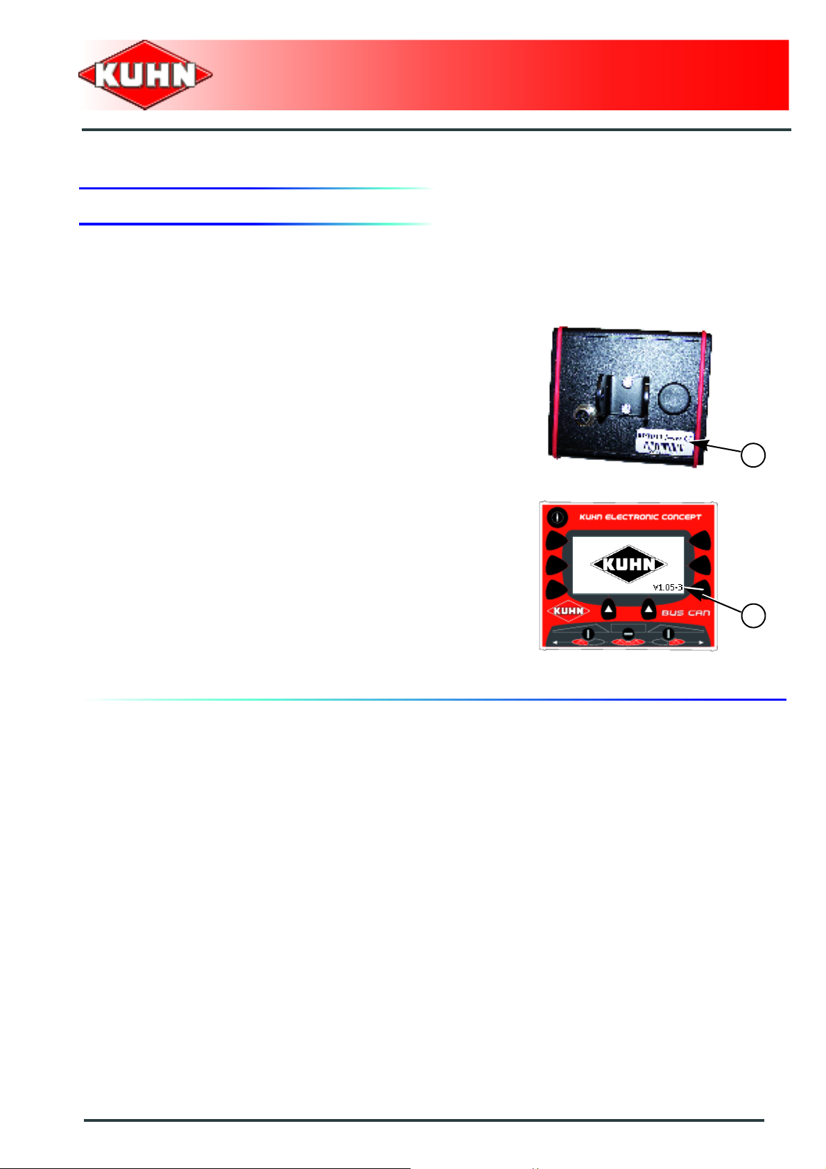
2. Manufacturers' marking
Please note the serial number of your equipment.
This information is to be indicated to the de aler for all
spare parts orders.
- Serial no. (1):
Control box
RPB
1
When switched on, the control box displays the following
information:
- Control box version (1):
1
Control box identification
5
Page 8

3. Optional equipment
All equipments listed below are not always
compatible between each other or with your
machine.
See machine corresponding to a specific
configuration.
Check with your authorized KUHN dealer the
equipment compatibility with your machine.
Prior to using optional equipment, it is necessary
to define the parameters.
See concerned section in the "Configuration"
chapter.
Control box
RPB
Tick box corresponding to the equipment fitted on your
machine:
Working headlights
Flashing light
6
Control box identification
Page 9

$Safety
1. Description of symbols used in this document
This symbol indicates a potentially hazardous situation
that if not avoided, could result in serious bodily injury.
Control box
RPB
This symbol is used to identify special instructions or
procedures which, if not followed strictly, could result in
machinery damage.
This symbol is used to communicate technical
information of particular interest.
Safety
7
Page 10

2. Safety instructions
Introduction
The operator must follow the safety instructions in this
manual and in the machine's operator's manual as well
as respect the warnings posted on the machine. The
operator is also obliged to respect current legislation
concerning accident prevention, work safety and public
traffic circulation.
Read and follow the safety instructions
Before using the control box, carefully read all safety
instructions in this manual.
Before starting work, the operator must be familiar with
all machine controls, handling devices and their
functions. It is too late to learn once work has been
started!
Never let anyone operate the machine who is not trained
to do so.
Should you have any difficulties in understanding certain
parts in this manual, please contact your KUHN dealer.
Control box
RPB
Precautions to take before using the
control box
Place the control box so that it cannot interfere with other
tractor controls and be activated inadvertently.
Before switching the control box on, check that nobody
is within the machine pivoting area: switching on the
control box can activate functions on the machine.
8
Safety
Page 11

Precautions to take when using the control box
Do not operate the control box while a person is carrying
out work on the machine.
Switch off control box before carrying out any
maintenance or repair work on the machine.
Precautions when driving
Before transporting the machine on public road s, make
sure no function of the control box or of the control
accessories can be switched on inadvertently. Make
sure tractor valves and power take-off are deactivated
and not inadvertently engaged.
Control box
RPB
Safety
9
Page 12

$General description
1. Description and glossary
0
4
Control box
RPB
3
2
1
5
1 : Machine wiring harness 5-pin connector
2 : Control box mounting
3 : Keyboard with 8 function buttons and 1 On/Off button
4 : Screen
5 : Spraying opening and shut-off switches
10
General description
Page 13

2. Technical specifications
Dimensions:
Control box
RPB
Length
Width
Depth
Operating temperature from -20°C à +60°C
Storage temperature up to +85°C
Voltage input 12 V
Screen 120x 64 pixels
Connector Machine wiring harness 5-pin connector
Wiring harness CAN BUS
125 mm (4.9 ’’)
110 mm (4.3 ’’)
95 mm (3.7 ’’)
General description
11
Page 14

3. Description of control elements
Description of the controls
0
1
Control box
RPB
3
2
3
3
3
4
5
3
6
1 : Start/Stop: Control box
2 : Screen
3 : Selection key
4 : Switch: Left sequential opening/closing of the spraying sections
5 : Switch: Main opening/closing of the spraying sections
6 : Switch: Right sequential opening/closing of the spraying sections
3
3
3
12
General description
Page 15
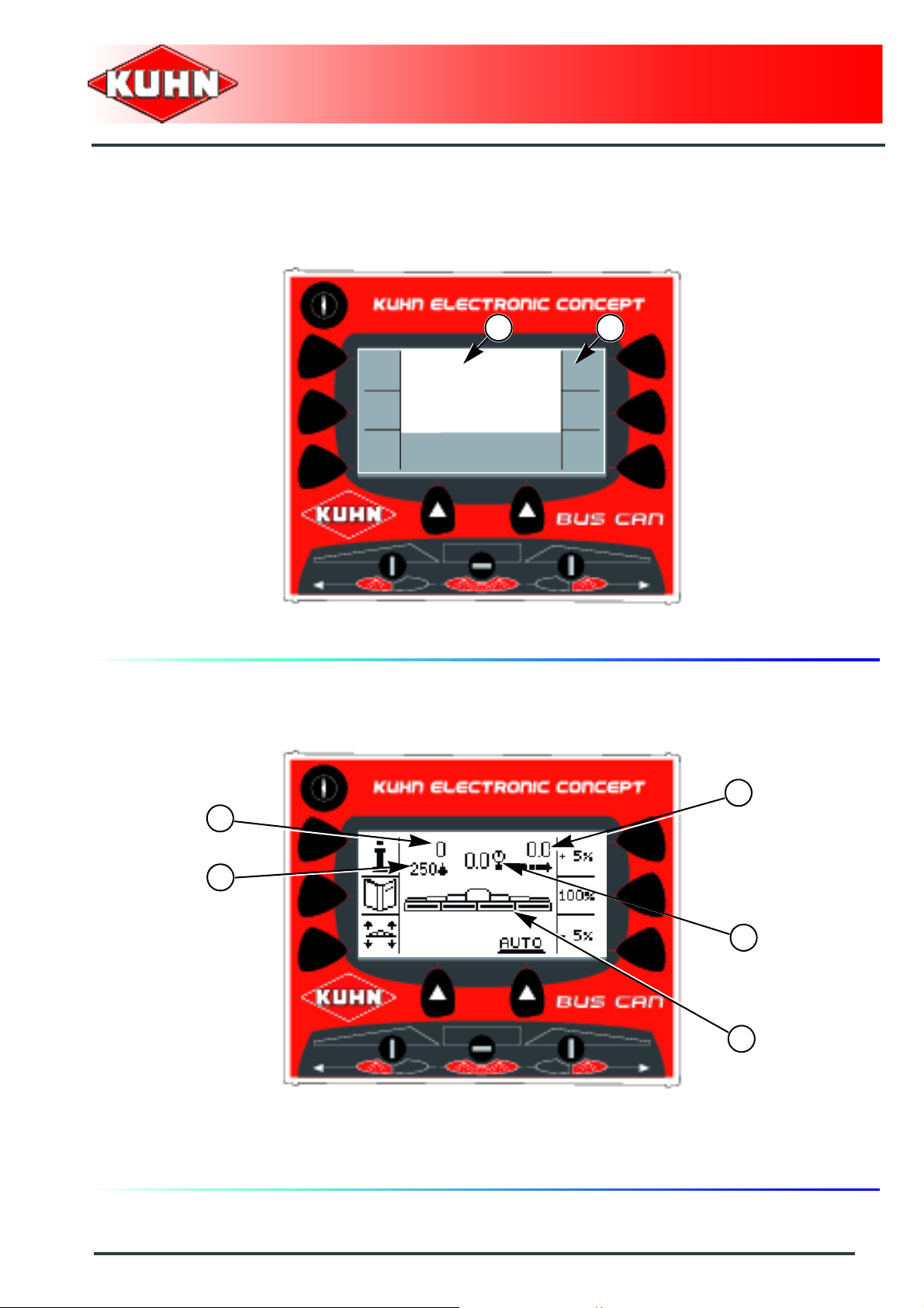
Description of screen zones
0
Control box
RPB
1
2
1 : Menu and data display 2 : Selection key display
Work screen description
0
5
2
1
3
4
1 : Programmed application rate 2 : Measured application rate
3 : Pressure 4 : Spraying sections
5 : Groundspeed
General description
13
Page 16

4. Access and menu navigation
Navigation keys
Control box
RPB
To navigate in the menus,use the following keys:
- Menu line change key (1).
- Selection validation key (2).
- Key to return to the previous menu (3).
Menu display (1).
1
2
1
3
1
The RPB control box features circular menus.
14
General description
Page 17

Entry and modification of a value
- Press keys (1) and (2) to select the parameter to
modify:
• Move the cursor upwards (1).
• Move the cursor downwards (2).
Control box
RPB
1
3
- Press key (3) to modify parameter.
Numerical value:
- Press keys (1) or (2) to modify the value:
• Increment a value (1).
• Decrement a value (2).
• Value reset ( 3).
- Validate (4).
or
- Cancel the modification (5).
Alphabetical value:
- Press keys (1) or (2) to select the value to modify:
• Move the cursor to the right (1).
• Move the cursor to the left (2).
2
1
3
4
2
3
5
5
- Press keys (3) or (4) to modify the value:
• Increment a value (3).
• Decrement a value (4).
• Value reset ( 5).
- Validate (6).
or
- Cancel the modification (7).
6
4
2
General description
7
1
15
Page 18
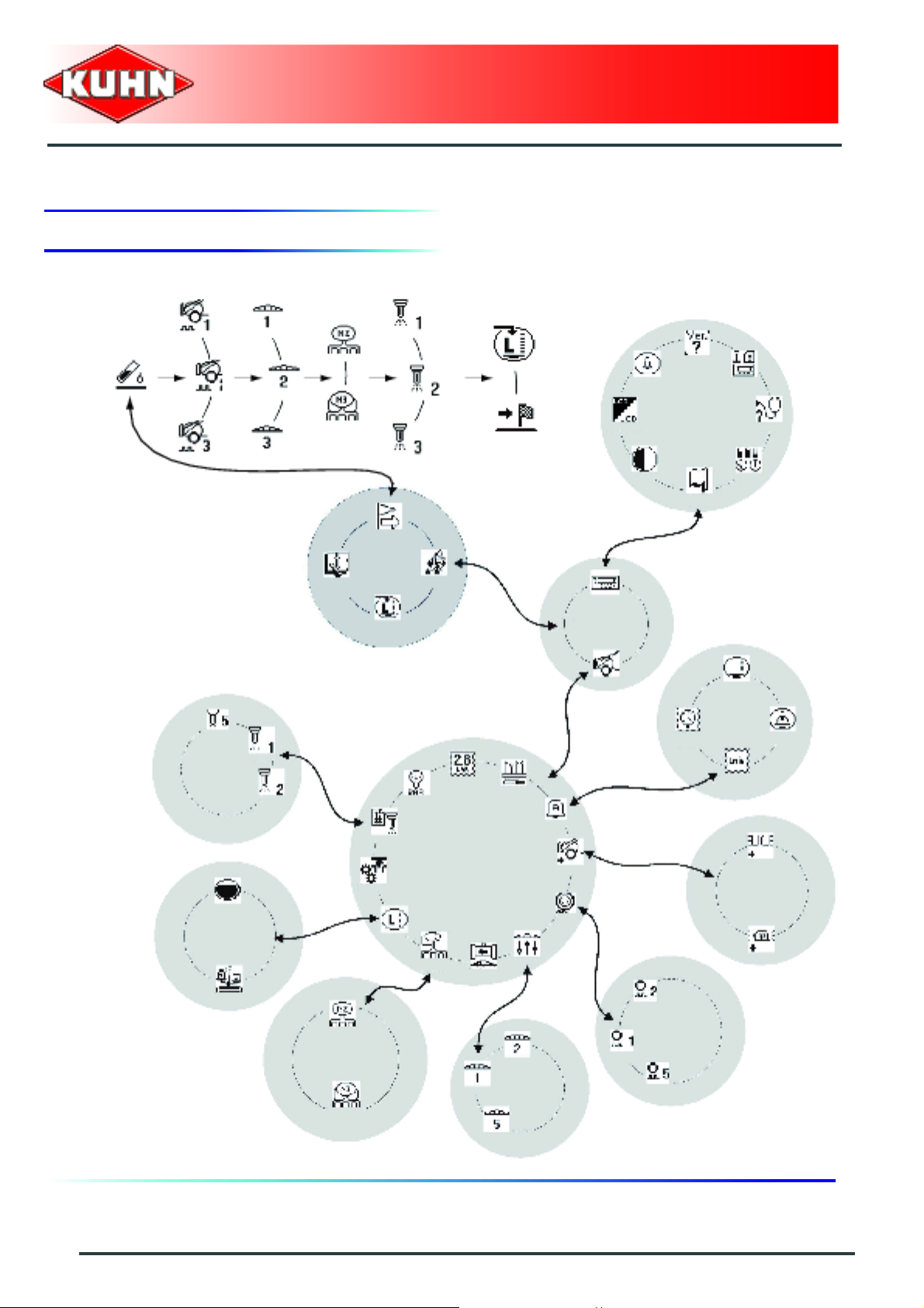
5. Menu tree structure
Control box
RPB
Terminal
Nozzles
Tank
Main menu
Settings
Alarms
Sprayer
Optional equipment
16
General description
Wheels
Circulation
Booms
Page 19

$Assembly and fitting
1. Tractor requirements
The tractor must supply a voltage comprised between
11 V and 14 V.
2. Description of the connection
Control box
RPB
Never connect battery charger or perform
welding tasks without having previously
disconnected the control box.
- Connect the machine 3-pin power plug (1).
- Connect machine CAN BUS wiring harness connector
(2) to the control box.
For increased safety, it is recommended to use the
harness supplied with the machine..
Check that the connectors are in a good
condition and clean.
2
1
- Connect the wiring harness directly to the battery
terminals respecting the polarities.
Assembly and fitting
17
Page 20

3. Positioning and parking
The control box must be easily accessible
from the tractor cab.
The control box must be fitted in a dry place,
safe from bad weather.
Control box mounting
The control box is placed in the tractor cabin on support
(1) to mount.
Control box
RPB
1
Control box removal
Disconnect and store control box in a dry and clean
place.
18
Assembly and fitting
Page 21

$Putting into service
1. Switches on the control box
Control box
RPB
- Press key (1) to switch the control box on.
- Press key (1) for 2 seconds to switch the control box
off.
2. Standby mode
The control box RPB switches to the standby mode
when not used for a few minutes.
- Press on a key to exit the standby mode.
1
Putting into service
19
Page 22

$Configuration
The configuration modification must be
made by your KUHN authorized dealer.
-
Control box
RPB
Main menu
Starting from the main menu:
- Press key (1) to access the "Settings" menu.
- Press key (1) to enter the password.
Settings
1
1
Password: 7
- Press 7 time on key (1).
- Press the button (2) to confirm.
To note user settings, refer to the section
"Appendix".
20
Configuration
1
2
Page 23

1. Adjustments before first use
Control box
RPB
Main menu
As from the "Configuration" menu:
- Press key (1) to access the "Terminal" menu.
- Press on the button (2).
Setting the language
- Press key (1) to access the menu.
- Press key (2) to change the language.
There are 4 different languages available to navigate in
the control box menus. By default, French and English
are always present.
Configuration
Terminal
2
1
1
2
FR: French
GB: English
ES: Spanish
DE: German
RO: Rumanian
DK: Danish
SK: Slovak
PL: Polish
LT: Lithuanian
JP: Japanese
RU: Russian
Configuration
21
Page 24

Setting contrast
- Press key (1) to access the menu.
- Press key (2) to modify the contrast.
Setting back-lighting
- Press key (1) to access the menu.
- Press key (2) to switch from one mode to the other.
No: White text on black background.
Yes: Black text on white background.
Control box
RPB
1
2
1
2
Beep keys
- Press key (1) to access the menu.
- Press key (2) to switch from one mode to the other.
No: No noise.
Beep: Low noise.
Buzzer: Loud noise.
1
2
22
Configuration
Page 25

System
- Press key (1) to access the menu.
- Press on the button (2).
Speed simulator:
The stimulator allows stationary spraying.
- Press key (1) to modify parameter.
Yes: Activated.
No: Deactivated.
Control box
RPB
2
1
1
When starting to move, the speed simulator is
automatically deactivated.
Configuration
23
Page 26
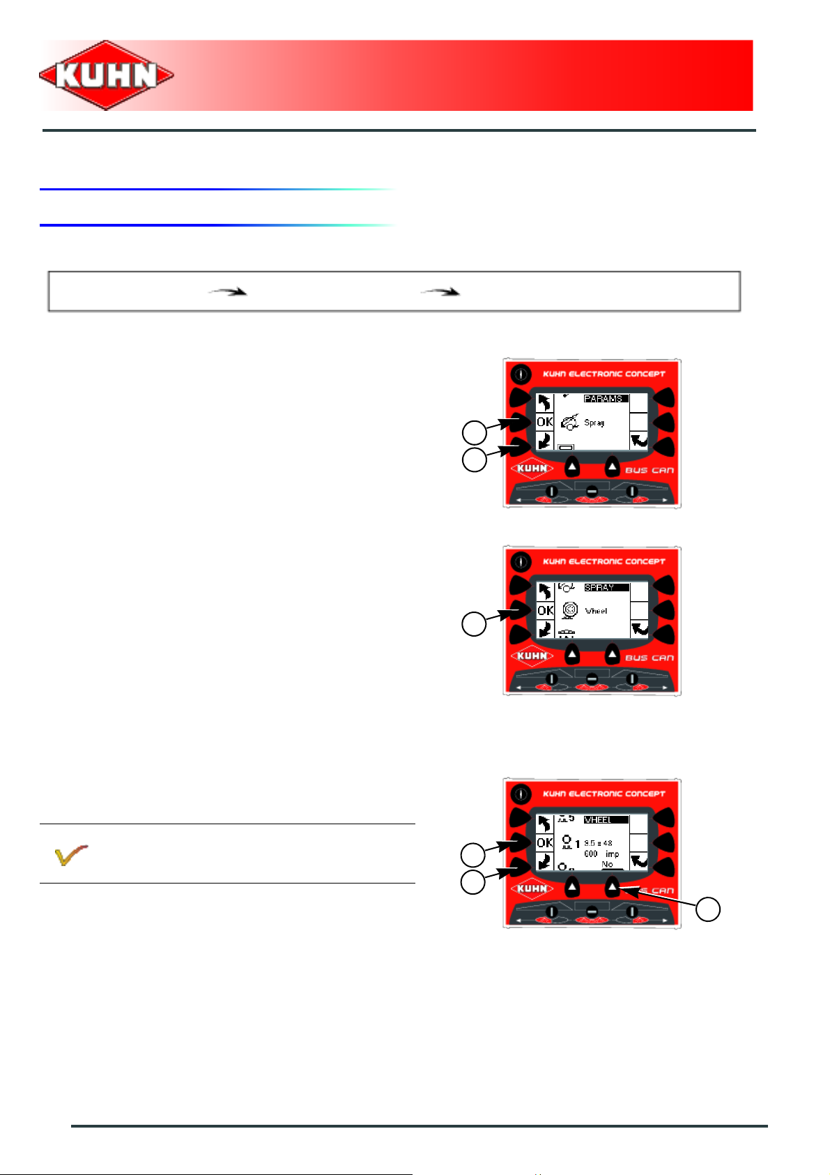
2. Preliminary adjustments at work
Control box
RPB
Main menu
As from the "Configuration" menu:
- Press key (1) to access "Sprayer" menu.
- Press on the button (2).
Wheel
- Press on the button (1).
The control box can save up to 5 different configurations.
All configurations are factory preset. All configurations
can be modified.
Configuration
Sprayer
2
1
1
Activate / deactivate a configuration:
- Press key (1) to select a configuration.
- Press key (2) to switch from one mode to the other.
No: Configuration deactivated.
Yes: Configuration activated.
- Press on the button (3).
24
Configuration
3
1
2
Page 27

Modifying a configuration:
- Press key (1) to access the parameters to modify.
Control box
RPB
Type:
- Press key (2) to modify parameter.
Number of pulses:
- Press key (2) to modify parameter.
Automatic calibration:
When used for the first time, the equipment must be
calibrated.
- Press key (3) to start the automatic calibration.
- Follow screen instructions.
2
3
1
Configuration
25
Page 28

Boom
- Press on the button (1).
The control box can save up to 5 different configurations.
All configurations are factory preset. All configurations
can be modified.
Activate / deactivate a configuration:
- Press key (1) to select a configuration.
- Press key (2) to switch from one mode to the other.
Control box
RPB
1
No: Configuration deactivated.
Yes: Configuration activated.
- Press on the button (3).
Modifying a configuration:
- Press key (1) to access the parameters to modify.
Name:
- Press key (2) to modify parameter.
Width:
- Press key (2) to modify parameter.
Number of nozzles:
- Press key (2) to modify parameter.
The control box enables managing up to 7
sections.
Section 1 corresponds to the section most to the
left of the boom.
3
1
2
2
1
26
Configuration
Page 29
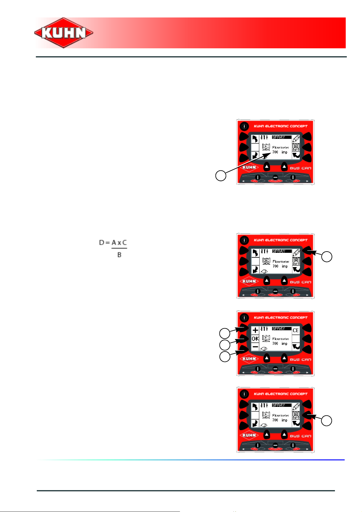
Spraying flowmeter
When used for the first time, the equipment must be
calibrated.
Manual calibration:
- Note the flowmeter coefficient (1) = A.
- Switch to stationary spraying mode.
- Go to manual mode.
- Adjust pressure to 3 bars (44 psi).
- Place a test tube underneath the nozzle.
- Reset counters.
- Open spraying.
- Wait for 10 seconds.
- Shut-off spraying.
- Measure the volume collected in the test tube.
- Multiply the volume collected in the test tube by the
number of nozzles on the boom = B.
- Note the volume displayed by the control box = C.
- Calculate the new coefficient value = D:
Control box
RPB
1
- Press key (1) to modify parameter.
- Pres on keys (1) and (2) to adjust the value.
- Press the button (3) to confirm.
Automatic calibration:
- Press key (1) to start the automatic calibration.
- Follow screen instructions.
1
1
3
2
1
Configuration
27
Page 30
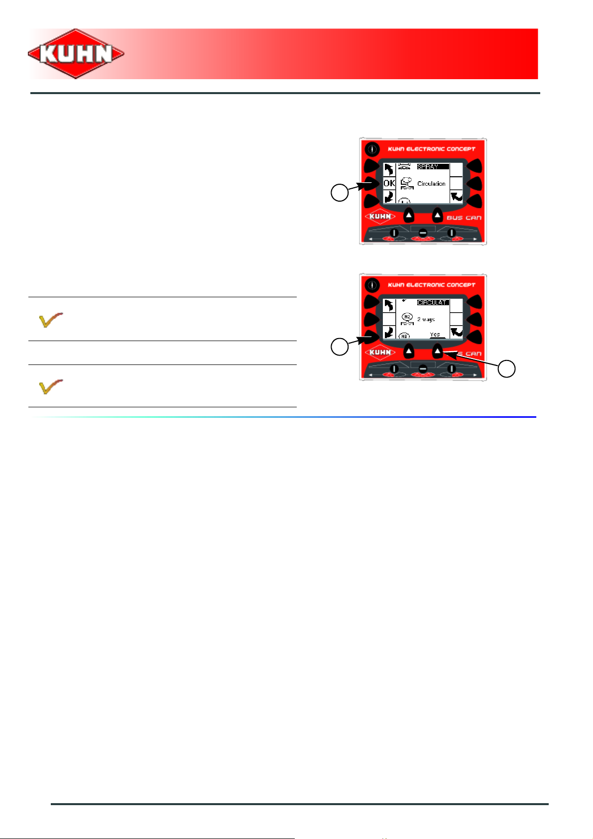
Circulation
- Press on the button (1).
Activate / deactivate a configuration:
- Press key (1) to select a configuration.
- 2-way standard circulation (N2).
- 3-way standard circulation (N3).
Refer to the machine operator's manual.
- Press key (2) to switch from one mode to the other.
Control box
RPB
1
1
No: Configuration deactivated.
Yes: Configuration activated.
2
28
Configuration
Page 31
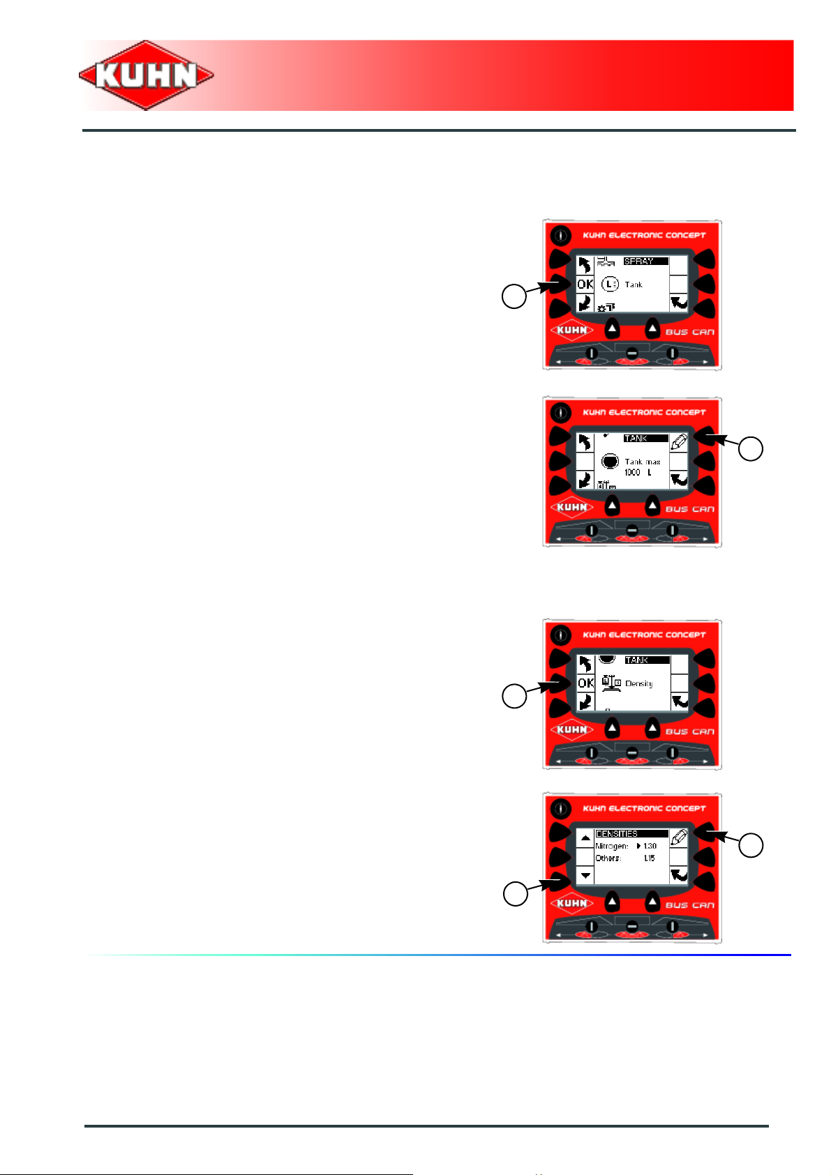
Tank
- Press on the button (1).
Body capacity:
Control box
RPB
1
- Press key (1) to modify parameter.
Density:
- Press on the button (1).
- Press key (1) to access the parameters to modify.
- Press key (2) to modify parameter.
1
1
2
1
Configuration
29
Page 32

Regulation
- Press on the button (1).
- Press key (1) to access the parameters to modify.
Control box
RPB
1
Pump coefficient:
This parameter allows filtering the pump flow variations.
The more the pump flow is varies, the more the
coefficient must be high. The more the pump flow is
stable, the more the coefficient must be low.
- Press key (2) to modify parameter.
Regulation coefficient:
This parameter allows adjusting the regulation speed
according to the regulation valve used. The slower the
valve opening/shut-off, the lower the coefficient must be
set. The faster the valve opens/closes, the higher the
coefficient must be set.
- Press key (2) to modify parameter.
2
1
2
30
Configuration
Page 33

Application rate adjustment:
This parameter allows defining the application rate
adjustment rate:
• 5% or 10% or 15% or 20% or 25%.
- Press key (2) to modify parameter.
Control box
RPB
2
Management of the minimum pressure:
Press key (2) to modify parameter.
No: During work at low speed, the application
rate adjustment is obtained by reducing the
pressure. The pressure goes below the
minimum nozzle working pressure. The spraying
is not even.
Yes: During work at low speed, the regulation
does not go below the minimum nozzle working
pressure. This regulation leads to an
overdosage.
Valve opening time:
This parameter indicates the time taken by the regulation
valve to fully open / close.
- Press key (2) to modify parameter.
2
2
Configuration
31
Page 34

Nozzles
- Press on the button (1).
Control box
RPB
Always calibrate the nozzles using water.
The control box can save up to 5 different configurations.
All configurations are factory preset. All configurations
can be modified.
Activate / deactivate a configuration:
- Press key (1) to select a configuration.
- Press key (2) to switch from one mode to the other.
No: Configuration deactivated.
Yes: Configuration activated.
- Press on the button (3).
Modifying a configuration:
- Press key (1) to access the parameters to modify.
1
3
1
2
Name:
- Press key (2) to modify parameter.
Flow to 3 bar (43.5 psi):
- Press key (2) to modify parameter.
Maximum pressure:
- Press key (2) to modify parameter.
MINIMUM operating pressure:
- Press key (2) to modify parameter.
2
1
32
Configuration
Page 35

Pressure sensor
- Press key (1) to switch from one mode to the other.
No: Sensor off.
Yes: Sensor on.
- Press on the button (2).
We recommend not to modify the initial
setting.
Automatic calibration:
The machine is calibrated at the factory.
Control box
RPB
2
1
For models fitted with a DPI control box:
- Turn off control box DPI.
- Press key (1) to start the automatic calibration.
- Follow screen instructions.
Pressure display
- Press key (1) to switch from one mode to the other.
No: Display deactivated.
Yes: Display activated.
1
1
Configuration
33
Page 36

Hydraulics
- Press key (1) to switch from one mode to the other.
No: For models without 3-function electro-
hydraulic valve
and
For models fitted with a solenoid valve
block.
Yes: For models fitted with a 3-function electro-
hydraulic selector.
For models fitted with a solenoid valve block:
The machine is fitted with a CH10 control box
that groups the hydraulic functions.
- Control box connection CH10.
The control box CH10 functioning and setting
are discribed in the complementary instructions
supplied.
Control box
RPB
1
34
Configuration
Page 37

Alarms
- Press on the button (1).
Flow alarm
This alarm indicates that the preset flow setting is not
reached.
- Press key (1) to switch from one mode to the other.
No: Alarm deactivated.
Beep: Alarm activated. Low noise.
Buzzer: Alarm activated. Loud noise.
Control box
RPB
1
2
- Press on the button (2).
- Press key (1) to modify parameter.
Trip: Time before the alarm is activated.
1
1
Configuration
35
Page 38

Pressure alarm
The alarm indicates the pressure is below/over the set
limit.
Refer to the nozzle configuration.
- Press key (1) to switch from one mode to the other.
No: Alarm deactivated.
Beep: Alarm activated. Low noise.
Buzzer: Alarm activated. Loud noise.
Control box
RPB
2
- Press on the button (2).
- Press key (1) to modify parameter.
Trip: Time before the alarm is activated.
-
1
1
36
Configuration
Page 39

Tank low level prewarning alarm
The alarm indicates that the tank level is below the set
limit.
- Press key (1) to switch from one mode to the other.
No: Alarm deactivated.
Beep: Alarm activated. Low noise.
Buzzer: Alarm activated. Loud noise.
- Press on the button (2).
Control box
RPB
2
1
- Press key (1) to modify parameter.
Trip: Tank level below which the alarm is
activated.
1
Configuration
37
Page 40

Tank low level alarm
The alarm indicates that the tank level is below the set
limit.
- Press key (1) to switch from one mode to the other.
No: Alarm deactivated.
Beep: Alarm activated. Low noise.
Buzzer: Alarm activated. Loud noise.
- Press on the button (2).
- Press key (1) to modify parameter.
Trip: Tank level below which the alarm is
activated.
Control box
RPB
2
1
1
38
Configuration
Page 41

Optional equipment
Do not activate optional equipment that is
not installed.
- Press on the button (1).
Control box
RPB
1
Flashing light
- Press key (1) to switch from one mode to the other.
No: Equipment not installed.
Yes: Equipment installed.
Working headlights
- Press key (1) to switch from one mode to the other.
No: Equipment not installed.
Yes: Equipment installed.
1
1
Configuration
39
Page 42
1. Tank
Control box
RPB
$Machine use
Refer to the machine operator's manual.
Main menu
Starting from the main menu:
- Press key (1) to access "Tank" menu.
The control box displays the following information:
- Tank rest.
Density
- Press key (1) to switch from one mode to the other.
Tank
1
1
40
Machine use
Page 43
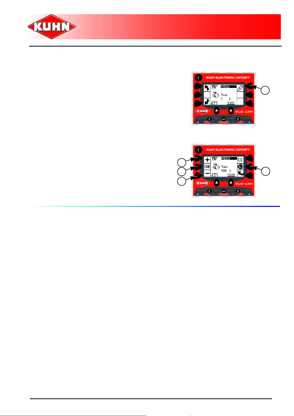
Filling
- Fill the tank.
- Press key (1) to modify parameter.
Full filling:
- Press on the button (1).
or
Control box
RPB
1
Partial filling:
- Pres on keys (2) and (3) to adjust the value.
- Press the button (4) to confirm.
2
4
1
3
Machine use
41
Page 44

2. Operating data
Control box
RPB
Main menu
Starting from the main menu:
- Press key (1) to access "Counters" menu.
- Press on the button (2).
The control box displays the following information:
- Partial volume.
- Partial area.
- Partial distance.
- Total volume.
- Total area.
- Total distance.
- Press key (1) to select the counter.
- Press key (2) to modify parameter.
Operating data
2
1
2
- Press key (1) for counter reset.
Press key (1) during 3 seconds to reset the
counters.
- Press the button 2 to confirm.
42
Machine use
1
1
2
Page 45

3. Spraying start
Control box
RPB
Main menu
Starting from the main menu:
- Press key (1) to access the "Spraying start" menu.
- Press on the button (2).
According to the configuration, the choices offered are
different:
- If several configurations are activated, the control box
offers a list of choices.
- If only one configuration is activated, the control box
selects automatically the configuration activated.
- If no configuration is activated, an error message is
displayed. Check the control box configuration.
Spraying start
2
1
Ap.rate:
- Press key (1) to modify parameter.
- Press the button (2) to confirm.
1
2
Machine use
43
Page 46

Wheel:
- Press key (1) to select a configuration.
- Press the button (2) to confirm.
Boom:
- Press key (1) to select a configuration.
- Press the button (2) to confirm.
Control box
RPB
2
1
2
1
Circulation:
- Press key (1) to select a configuration.
- Press the button (2) to confirm.
Nozzle:
- Press key (1) to select a configuration.
- Press the button (2) to confirm.
Activate the pressure display to display the list of
nozzles activated. See concerned section in the
"Configuration" chapter.
2
1
2
1
44
Machine use
Page 47

Operating data:
- Press key (1) to select the counter.
- Press key (2) to modify parameter.
- Press key (1) for counter reset.
Press key (1) during 3 seconds to reset the
counters.
Control box
RPB
2
1
1
- Press the button (2) to confirm.
The control box displays the work screen.
2
Machine use
45
Page 48

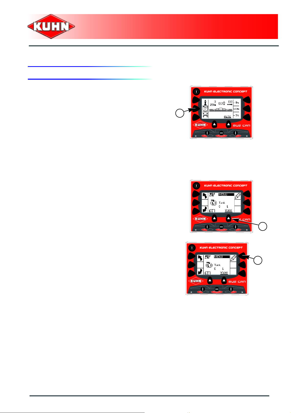
4. Information
To display the information screen:
- Press on the button (1).
The control box displays the following information:
•Flow.
• Partial area.
• The number of litres spread.
• Tank rest.
The control box automatically redisplays the work screen
after 10 seconds.
Control box
RPB
1
For a continuous information screen display:
- Press for approximately 3 seconds on key (1)
To redisplay the work screen:
- Press key (1) a second time.
46
Machine use
Page 49

5. Unfolding/folding of the boom arms
Check that nobody is within the machine
pivoting area. If there is someone, make su re
the person moves away.
If a speed exceeding 4 km/h is detected, the
control box switches into the slope corrector
mode.
For models fitted with a solenoid valve
block
Control box
RPB
The machine is fitted with a CH10 control box that
groups the hydraulic functions.
Refer to control box operator's manual.
For models fitted with a 3-function electro-
hydraulic selector
The boom activators provide following hydraulic
functions:
- Slope corrector (1).
- Unfolding/folding of the central arms (2).
- Unfolding / folding of the outer arms (3).
At startup, the slope corrector mode is automatically
activated.
Machine use
47
Page 50

Unfold the booms:
Unfold the central arms:
- Press on the button (1).
- Shift the tractor hydraulic valve.
Unfold the outer arms:
- Press on the button (1).
- Shift the tractor hydraulic valve.
- Press on the button (1).
The boom is unfolded.
Control box
RPB
1
1
Fold the booms:
Fold the outer arms:
- Press on the button (1).
- Shift the tractor hydraulic valve.
Fold the central arms:
- Press on the button (1).
- Shift the tractor hydraulic valve.
- Press on the button (1).
The boom is folded.
1
1
48
Machine use
Page 51

6. Application rate adjustment
To adjust the application rate adjustment rate,
see concerned section in the "Configuration"
section.
Control box
RPB
- Press key (1) to increase the programmed application
rate.
- Press key (2) to reduce the programmed application
rate.
To revert to the initial application rate, press key (1).
1
2
1
Machine use
49
Page 52

7. AUTO/MAN mode
- Press key (1) to switch from one mode to the other.
Automatic mode:
- The control box opens/closes the flow regulation valve
to maintain the programmed application rate.
Manual mode:
- Press keys (1) and (2) to open / shut the flow
regulation valve and adjust the spraying pressure.
Control box
RPB
1
1
2
50
Machine use
Page 53
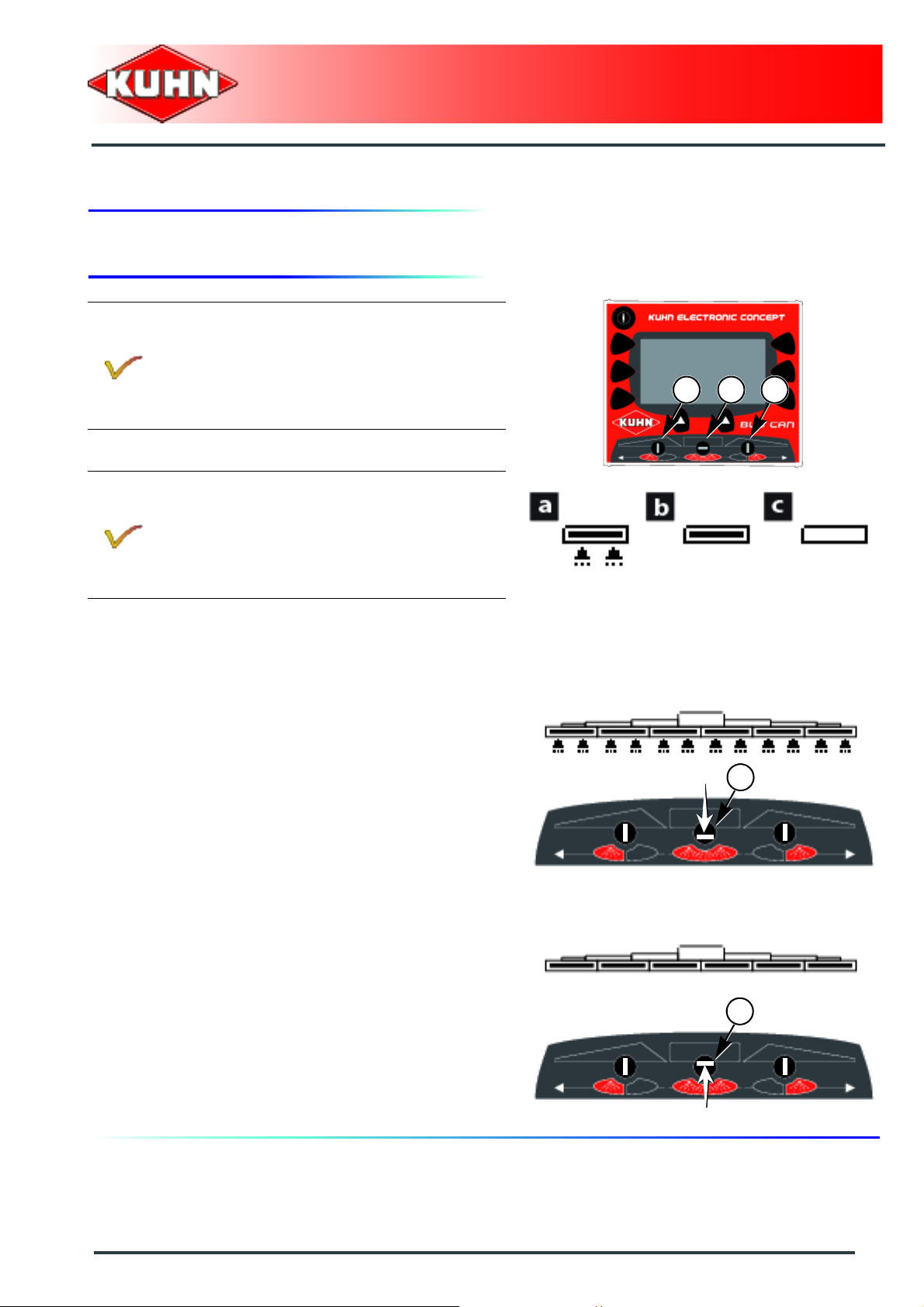
8. Opening/shut-off of the spraying sections
Switch (1): Left sequential opening/closing of the
spraying sections.
Switch (2): Main opening/closing of the spraying
sections.
Switch (3): Right sequential opening/closing of
the spraying sections.
Display a: Spraying open. Spraying section
open.
Display b: Spraying shut-off. Spraying section
open.
Display c: Spraying shut-off. Spraying section
shut off.
Control box
RPB
1 2 3
Spraying opening / shut-off
Spraying main opening:
- Operate switch (1) downwards.
Spraying main shut-off:
- Operate switch (1) upwards.
1
1
Machine use
51
Page 54

Main opening/closing of the spraying
sections
Control box
RPB
Main opening of the spraying sections:
- Operate and maintain switch (1) downwards during 2
seconds.
Main shut-off of the spraying sections:
- Operate and maintain switch (1) upwards during 2
seconds.
1
1
52
Machine use
Page 55

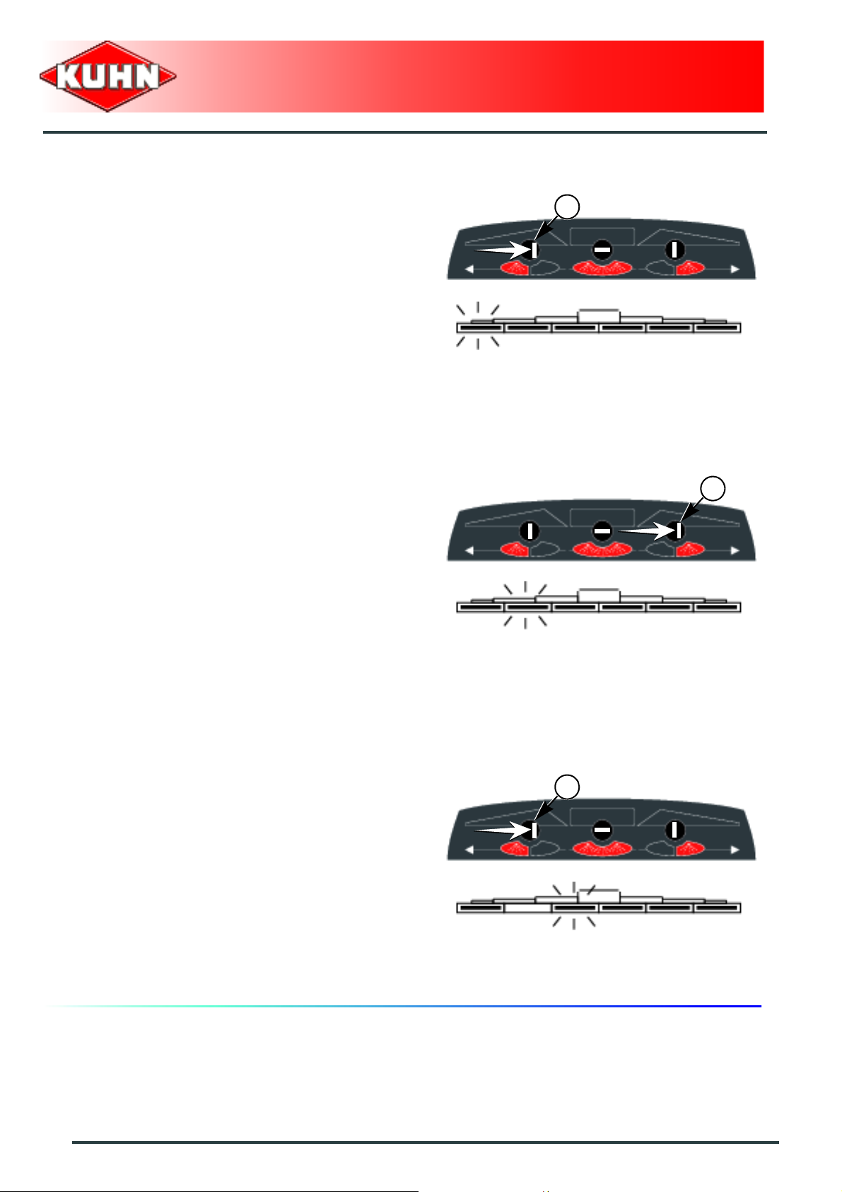
Sequential opening/closing of the spraying sections
Control box
RPB
Left sequential opening of the spraying sections:
- Operate switch (1) to the right.
- Repeat procedure for each section.
Left sequential shutting of the spraying sections:
- Operate switch (1) to the right.
- Repeat procedure for each section.
1
1
Machine use
53
Page 56

Control box
RPB
Right sequential opening of the spraying sections:
- Operate switch (1) to the left.
- Repeat procedure for each section .
Right sequential shutting of the spraying sections:
- Operate switch (1) to the left.
- Repeat procedure for each section .
1
1
54
Machine use
Page 57

Partial opening / shutting of the spraying sections
Section preselection to the right:
- Operate and maintain switch (1) to the left during 2
seconds.
Control box
RPB
1
Open the section:
- Operate switch (1) to the left.
Shut-off the section:
- Operate switch (1) to the left.
1
1
Machine use
55
Page 58
Section preselection to the left:
- Operate and maintain switch (1) to the right during 2
seconds.
Control box
RPB
1
Open the section:
- Operate switch (1) to the right.
Shut-off the section:
- Operate switch (1) to the right.
1
1
56
Machine use
Page 59
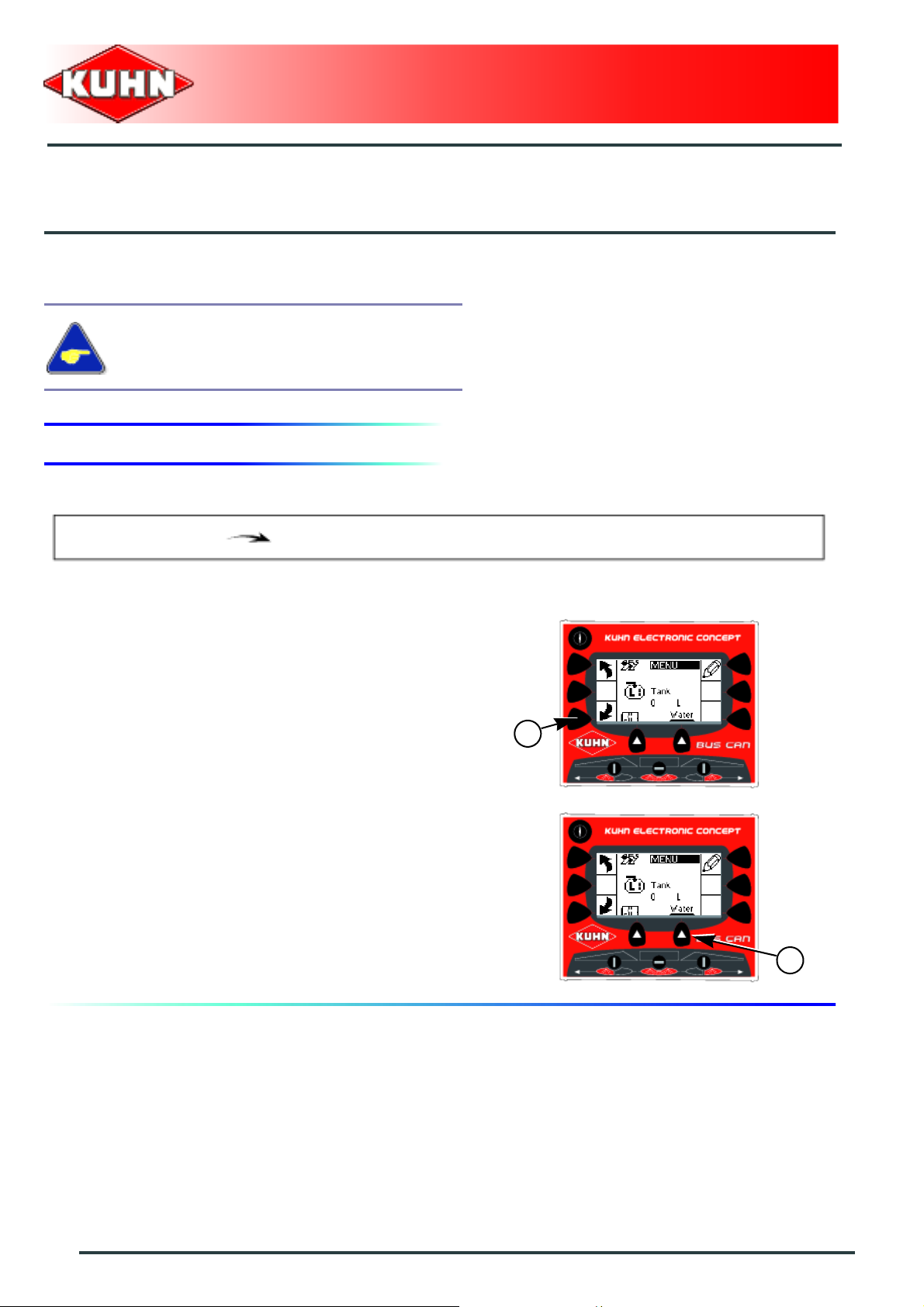
9. "Menu" key
To display the "Menu" screen:
- Press on the button (1).
Tank
The control box displays the following information:
- Tank rest.
Control box
RPB
1
Density
- Press key (1) to switch from one mode to the other.
Filling
- Fill the tank.
- Press key (1) to modify parameter.
1
1
Machine use
57
Page 60

Full filling:
- Press on the button (1).
or
Partial filling:
- Pres on keys (2) and (3) to adjust the value.
- Press the button (4) to confirm.
Work end
- Press on the button (1).
Control box
RPB
2
4
3
1
1
58
Machine use
Page 61

$Optional equipment
1. Work spotlights and flashing light
The work spotlights and flashing light can be
switched on simultaneously.
Working headlights
- Press key (1) to switch from one mode to the other.
Control box
RPB
Display a: Work lights off.
Display b: Work lights on.
Flashing light
- Press key (1) to switch from one mode to the other.
Display a: Flashing light off.
Display b: Flashing light on.
1
1
Optional equipment
59
Page 62
$Maintenance and storage
1. Maintenance
When cleaning the machine, never point the
water jet on the control box.
The control box does not require any particular
maintenance, in the case of a breakdown or a
malfunction call your KUHN technician.
Control box
RPB
2. Storage
At the end of each season
- Store control box in a dry place free of dust.
At the start of each season
- Re-read the operators' manual.
60
Maintenance and storage
Page 63

$Trouble shooting guide
Problem Cause Remedy
Check plug voltage (12V).
Check if the electrical power
The control box does not
come on and controls no
functions.
The speed is incorrect.
Over or underdosage. Incorrect control box setting.
Faulty electric power supply.
The control box is faulty
Faulty sensor.
Incorrect sensor adjustment.
cable of the control box is
connected.
Refer to the section
"Assembly and fitting".
Contact you KUHN
authorized dealer.
Verify speed sensor and
wiring function.
Immediately replace worn or
damaged parts with genuine
KUHN parts.
Carry out the calibration.
See concerned section in the
"Configuration" chapter.
See concerned section in the
"Configuration" chapter.
Contact you KUHN
authorized dealer.
Control box
RPB
Trouble shooting guide
61
Page 64

1. Alarms
To configurate the alarms, see section in the
"Settings" chapter.
If several alarms are activated simultaneously,
the alarm messages are displayed successively.
Flow alarm
This alarm indicates that the preset flow setting is not
reached.
Control box
RPB
Maximum flow alarm
The control box displays an alarm message.
2 "beeps" sound.
Remedy:
- Reduce the pump flow.
or
- Reduce ground speed.
Minimum flow alarm
The control box displays an alarm message.
2 "beeps" sound.
Remedy:
- Increase the pump flow.
or
- Increase forward speed.
62
Trouble shooting guide
Page 65

Pressure alarm
The alarm indicates the pressure is below/over the set
limit.
Maximum pressure alarm
The control box displays an alarm message.
2 "beeps" sound.
Remedy:
- Check the type of nozzle. Replace if necessary.
or
- Reduce ground speed.
Minimum pressure alarm
The control box displays an alarm message.
2 "beeps" sound.
Control box
RPB
Remedy:
- Increase the pump flow.
or
- Increase forward speed.
Tank low level alarm
The alarm indicates that the tank level is below the set
limit.
Tank low level prewarning alarm
The control box displays an alarm message.
2 x 3 "beeps" sound.
Tank low level alarm
The control box displays an alarm message.
5 "beeps" sound.
Trouble shooting guide
63
Page 66

2. Diagnosis
Control box
RPB
Main menu
As from the "Terminal" menu:
- Press key (1) to access the "Diagnosis" menu.
- Press on the button (2).
or
As from any screen:
- Simultaneously press keys (1) and (2) for
approximately 3 seconds.
Configuration
Terminal
2
1
Diagnosis
11
The diagnosis menu enables controlling the machine's
electric system (Battery voltage, Sensors...).
64
Trouble shooting guide
Page 67

3. Description of fuses
Prior to any maintenance or repair on the
junction box, disconnect the machine and
tractor power supply.
Never replace damaged fuse by a fuse of
higher value.
Keep fuses safe from rain and humidity.
The cards are made up of 4 tie-point blocks:
- (1) Signalling.
- (2) Outputs.
- (3) Sensors.
-(4) BUS CAN.
Control box
RPB
4
3
2
The terminal blocks have 3 levels:
(1) High.
(2) Middle.
(3) Low.
1
1
3
2
Trouble shooting guide
65
Page 68

Housing: Powered valves
Outputs:
Gy H: Relay control.
Gy M: +12V Flashing light.
1H: Filling stop valve 1M: Filling stop valve +
2H: Main stop valve 2M: Main stop valve +
3H: Flow regulation valve 3M: Flow regulation valve +
4H: Section valve 1 4M: Section valve 1 +
5H: Section valve 2 5M: Section valve 2 +
6H: Section valve 3 6M: Section valve 3 +
7H: Section valve 4 7M: Section valve 4 +
8H: Section valve 5 8M: Section valve 5 +
9H: Section valve 6 9M: Section valve 6 +
10H: Section valve 7 10M: Section valve 7 +
11H: Section valve 8 11M: Section valve 8 +
12H: Section valve 9 - / Options.
12M: Section valve 9 + / Options.
13H: Section valve 10 - / Options.
13M: Section valve 10 + / Options.
14H: Section valve 11 - / Options.
14M: Section valve 11 + / Options.
15H: Function selector central arms.
15M: Function selector outer arms.
Control box
RPB
4
3
2
1
From 1B to 15B: Ground.
Fuse:
Fuse (1): Flashing light.
Fuse (2): Sensors.
Fuse (3): BUS CAN.
Fuse (4): Supply.
66
Trouble shooting guide
Page 69

Sensors:
1M: Signal frequency: Wheel.
2M: Signal frequency: Flowmeter.
3M: Signal frequency: Return flowmeter.
4M: Signal frequency: Filling flowmeter.
5M: Analog signal: Pressure sensor.
6M: Analog signal: Electronic gauge.
7M: Reserved.
8M: Reserved.
From 1H to 8H: +12V.
From 1B to 8B: Ground.
Control box
RPB
BUS CAN:
Harness connection:
From 1H to 4H.
or
From 1M to 4M.
or
From 1B to 4B.
1: +12V.
2: CAN HIGH.
3: CAN LOW.
4: Ground.
Blue
Brown
White
Black
Trouble shooting guide
67
Page 70

Housing: Solenoid valve block
Outputs:
Gy H: Relay control.
Gy M: +12V Flashing light.
1H: Reserved.
1M: Reserved.
2H: Reserved.
2M: Reserved.
3H: On / Off.
3M: Automatic / Manual.
4H: Left outer arm opening.
4M: Left outer arm closing.
5H: Opening central arms.
5M: Closing central arms.
6H: Right outer arm opening.
6M: Right outer arm closing.
7H: Auxiliary down.
7M: Auxiliary up.
8H: Locking.
8M: Unlocking.
9H: Lowering left variable geometry.
9M: Raising left variable geometry.
10H: Lowering right variable geometry.
10M: Raising right variable geometry.
11H: Lowering height.
11M: Raising height.
12H: Slope left.
12M: Slope right.
13H: Drawbar left.
13M: Drawbar right.
14H: Reserved.
14M: Reserved.
15H: Reserved.
15M: BYPASS valve.
Control box
RPB
Supply
Outputs Sensors BUS CAN
Signalling
From 1B to 15B: Ground.
68
Trouble shooting guide
Page 71

Sensors:
1M: Signal frequency: Wheel.
2M: Analog signal: Gauge.
3M: Analog signal: Follower axle/Self-steering axle:
Front.
4M: Analog signal: Follower axle/Self-steering axle:
Rear.
5M: Reserved.
6M: Analog signal: Height.
7M: Reserved.
8M: Signal frequency: Reverse.
From 1H to 8H: +12V.
From 1B to 8B: Ground.
Control box
RPB
BUS CAN:
Harness connection:
From 1H to 4H.
or
From 1M to 4M.
or
From 1B to 4B.
1: +12V.
2: CAN HIGH.
3: CAN LOW.
4: Ground.
Blue
Brown
White
Black
Trouble shooting guide
69
Page 72

4. Factory counters
Control box
RPB
Main menu
As from the "Terminal" menu:
- Press key (1) to access "Counters" menu.
- Press on the button (2).
The control box displays the following information:
- Total area.
- Total volume.
These counters cannot be deleted.
Configuration
Terminal
2
1
Operating data
70
Trouble shooting guide
Page 73

5. Version
Control box
RPB
Main menu
As from the "Terminal" menu:
- Press key (1) to access the "Version" menu.
The control box displays the following information:
- Control box version.
Configuration
Terminal
1
Version
Trouble shooting guide
71
Page 74
1. Configuration
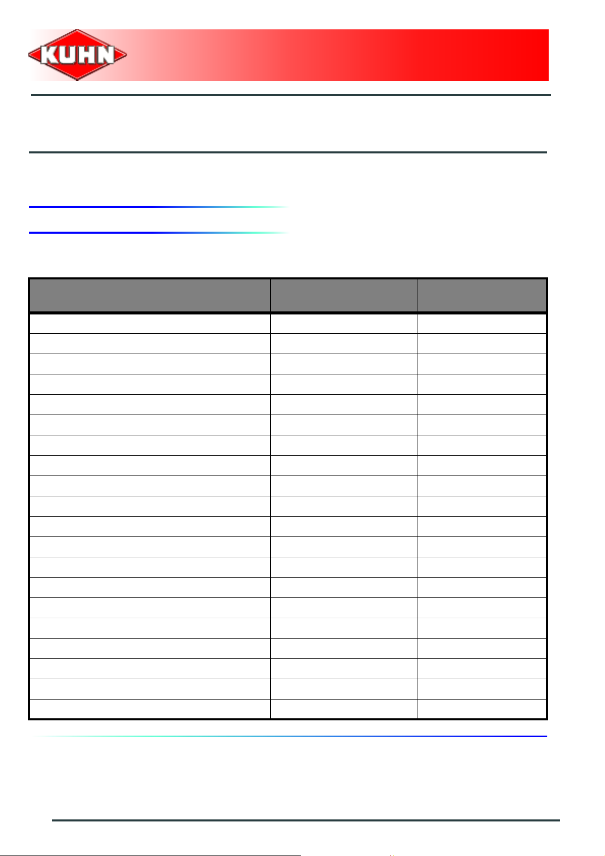
Wheels
Wheel 1
Status No
Control box
RPB
$Appendix
Factory settings User settings
Wheel 2
Wheel 3
Wheel 4
Wheel 5
Type 9.5 x 48
Number of pulses 600
Status Yes
Type 12.4 x 46
Number of pulses 585
Status No
Type 11.2 x 48
Number of pulses 577
Status No
Type 11.2 x 54
Number of pulses 528
72
Status No
Type 13.6 x 38
Number of pulses 646
Appendix
Page 75
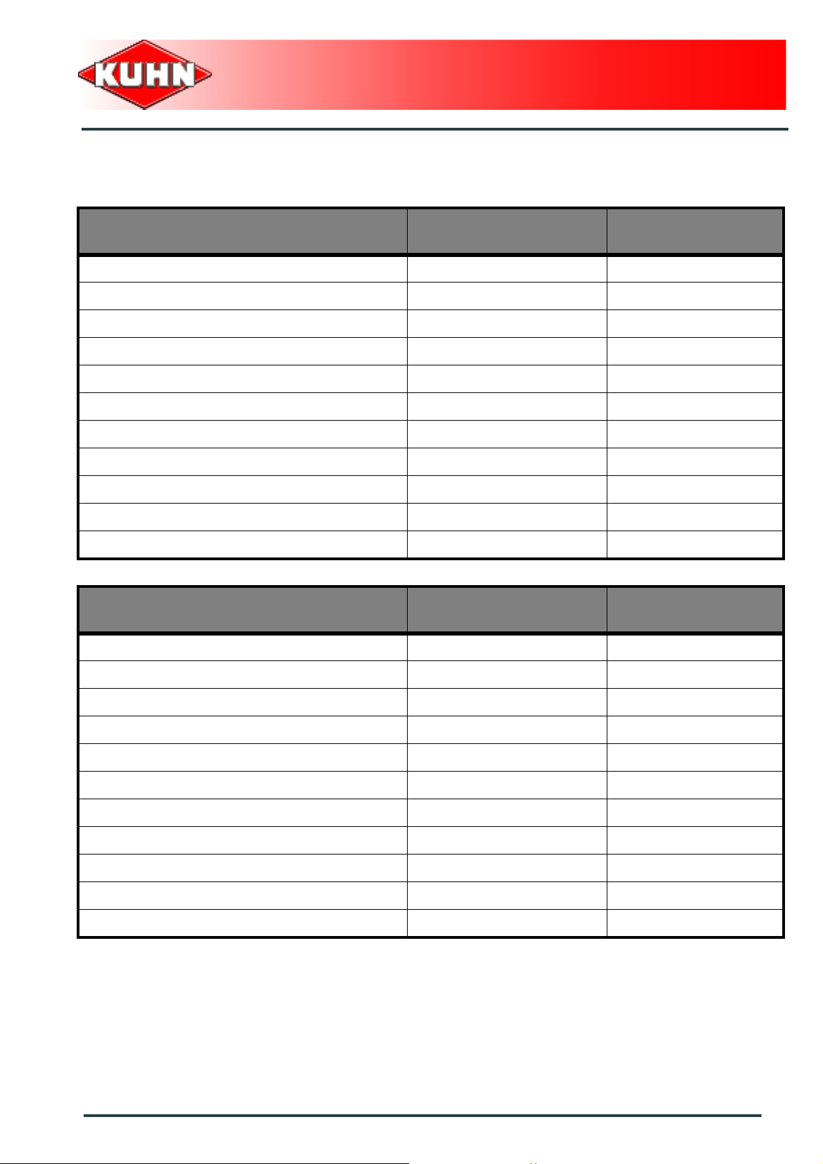
Booms
Boom 1
Control box
RPB
Factory settings User settings
Status No
Name Boom 1
Width 0.5 m (1’8’’)
Number of nozzles section 1 10
Number of nozzles section 2 11
Number of nozzles section 3 11
Number of nozzles section 4 10
Boom 2
Number of nozzles section 5 0
Number of nozzles section 6 0
Number of nozzles section 7 0
Factory settings User settings
Status No
Name Boom 2
Width 1.0 m (3’3’’)
Number of nozzles section 1 2
Number of nozzles section 2 0
Number of nozzles section 3 0
Number of nozzles section 4 0
Number of nozzles section 5 0
Number of nozzles section 6 0
Number of nozzles section 7 0
Appendix
73
Page 76

Boom 3
Control box
RPB
Factory settings User settings
Status No
Name Boom 3
Width 1.0 m (3’3’’)
Number of nozzles section 1 1
Number of nozzles section 2 1
Number of nozzles section 3 0
Number of nozzles section 4 0
Number of nozzles section 5 0
Number of nozzles section 6 0
Boom 4
Number of nozzles section 7 0
Factory settings User settings
Status No
Name Boom 4
Width 2.0 m (6’7’’)
Number of nozzles section 1 2
Number of nozzles section 2 2
Number of nozzles section 3 0
Number of nozzles section 4 0
Number of nozzles section 5 0
Number of nozzles section 6 0
Number of nozzles section 7 0
74
Appendix
Page 77
Boom 5
Control box
RPB
Factory settings User settings
Status No
Name Boom 5
Width 5.0 m (16’5’’)
Number of nozzles section 1 3
Number of nozzles section 2 2
Number of nozzles section 3 2
Number of nozzles section 4 3
Number of nozzles section 5 0
Number of nozzles section 6 0
Number of nozzles section 7 0
Spraying flowmeter
Factory settings User settings
Number of pulses 680
Circulation
Factory settings User settings
2-way standard circulation (N2)
Status No
3-way standard circulation (N3)
Status No
Appendix
75
Page 78
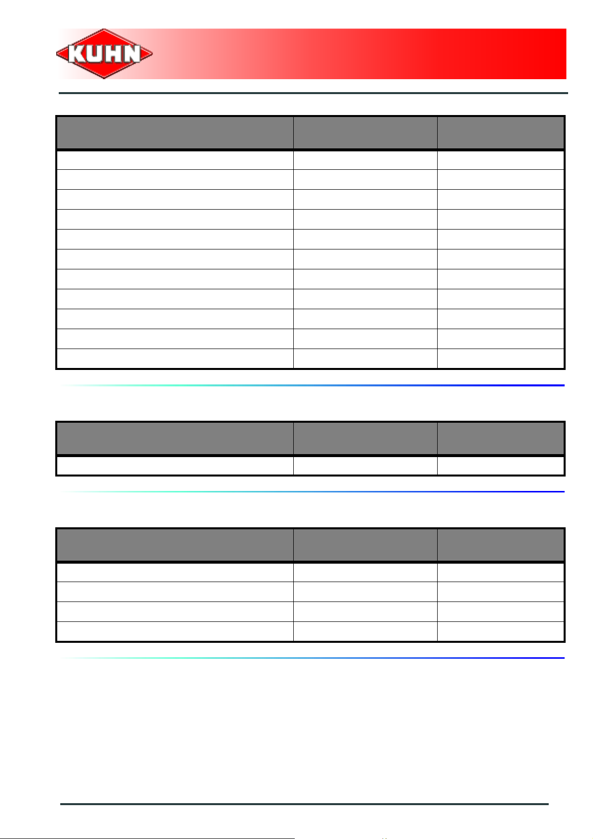
Tank
Factory settings User settings
Capacity 1000 L (264 US gal)
Density
Nitrogen 1.30
Others 1.15
Regulation
Factory settings User settings
Control box
RPB
Pump coefficient 200
Regulation coefficient 20
Application rate adjustment 5%
Management of the minimum pressure No
Valve opening time 9 s
Nozzles
Factory settings User settings
Nozzle 1
Status Yes
Name Orange
-1
Flow to 3 bar (43.5 psi) 0.4 L/min
Maximum pressure 7 bar (102 psi)
MINIMUM operating pressure 1.5 bar (22 psi)
(0.11 US gal/min-1)
76
Appendix
Page 79

Nozzle 2
Nozzle 3
Factory settings User settings
Status No
Name Green
Flow to 3 bar (43.5 psi) 0.6 L/min
Maximum pressure 7 bar (102 psi)
MINIMUM operating pressure 1.5 bar (22 psi)
Status No
Name Yellow
Flow to 3 bar (43.5 psi) 0.8 L/min
-1
(0.16 US gal/min-1)
-1
(0.21 US gal/min-1)
Control box
RPB
Nozzle 4
Nozzle 5
Maximum pressure 7 bar (102 psi)
MINIMUM operating pressure 1.5 bar (22 psi)
Status No
Name Lilac
Flow to 3 bar (43.5 psi) 1 L/min
-1
(0.26 US gal/min-1)
Maximum pressure 7 bar (102 psi)
MINIMUM operating pressure 1.5 bar (22 psi)
Status No
Name Blue
Flow to 3 bar (43.5 psi) 1.2 L/min
-1
(0.32 US gal/min-1)
Maximum pressure 7 bar (102 psi)
MINIMUM operating pressure 1.5 bar (22 psi)
Appendix
77
Page 80

Pressure sensor
Factory settings User settings
Status No
Pressure display
Factory settings User settings
Status No
Control box
RPB
Hydraulic functions
Factory settings User settings
Status No
78
Appendix
Page 81

Alarms
Flow alarm
Status Beep
Trip 5 s
Pressure alarm
Status Beep
Trip 5 s
Tank low level prewarning alarm
Status Beep
Control box
RPB
Factory settings User settings
Trip 0 L (0 US gal)
Tank low level alarm
Status Beep
Trip 0 L (0 US gal)
Optional equipment
Working headlights
Status No
Flashing light
Status No
Factory settings User settings
Appendix
79
Page 82

$Limited warranty
Control box
RPB
80
Limited warranty
Page 83

Control box
RPB
Limited warranty
81
Page 84

 Loading...