

Page 1

Complementary instructions
RC007BGB B
Control box
Software version: 3.70
Quantron S
RC007BGB B
- English - 11-2009
Page 2

Page 3

Control box
Quantron S
$Dear Owner
In buying a Kuhn machine you have chosen wisely. Into it have gone years of thought, research and
improvement. You will find, as have thousands of owners all over the world, that you have the best that
engineering skill and actual field testing can produce. You have purchased a dependable machine, but only
through proper care and operation can you expect to receive the performance and long service built into it.
This manual contains all the necessary information for you to receive full efficiency from your machine. The
performance you get from this machine is largely dependent on how well you read and understand this manual
and apply this knowledge. Please DO NOT ASSUME YOU KNOW HOW TO OPERATE AND MAINTAIN YOUR
MACHINE before reading this manual carefully. KEEP THIS MANUAL AVAILABLE FOR REFERENCE. Pass
it on to the next owner if you re-sell the machine.
Your KUHN dealer can offer a complete line of genuine KUHN service parts. These parts are manufactured and
carefully inspected in the same factory that builds the machine to assure high quality and accurate fitting of any
necessary replacements.
About improvements
We are continually striving to improve our products. It therefore reserves the right to make improvements or
changes when it becomes practical to do so, without incurring any obligations to make changes or additions to
the equipment sold previously.
Designated use of the machine
The Quantron S control box is exclusively designed for monitoring the application rate of Kuhn seed drills. Any
use outside this application is not permitted.
The intended use of the machine includes following all operation, maintenance and repair recommendations
given by the manufacturer, and using only genuine spare parts, equipment and accessories, as recommended
by the manufacturer.
The control box must only be operated, maintained and repaired by qualified persons who are familiar with the
machine's specifications and operation as well as safety regulations and procedures for preventing accidents.
The user must conform with the safety regulations given in this manual and the warnings located on the
machine. He must also respect general rules in terms of accident prevention, occupational medicine and road
regulations.
The manufacturer is not held liable for any damage or accidents resulting from control box modifications carried
out by the operator himself or any third party.
Dear Owner
1
Page 4

Control box
Quantron S
$Contents
Dear Owner .....................................................................................................................1
Contents..........................................................................................................................2
Control box identification..............................................................................................5
Front view..........................................................................................................................................5
Manufacturers' marking...................................................................................................................6
Safety...............................................................................................................................7
Description of symbols used in this document.............................................................................7
Safety instructions ...........................................................................................................................8
General description......................................................................................................10
Description......................................................................................................................................10
Technical specifications ................................................................................................................ 11
Description of control elements....................................................................................................12
Menu structure................................................................................................................................ 14
Assembly and fitting ....................................................................................................15
Tractor requirements......................................................................................................................15
Electrical connection .....................................................................................................................15
Control box connection .................................................................................................................16
Putting into service ......................................................................................................17
Switches on the control box..........................................................................................................17
2
Access and menu navigation........................................................................................................18
Basic adjustments..........................................................................................................................19
Contents
Page 5

Control box
Quantron S
Machine use ................................................................................................................. 24
Adjustments before first use......................................................................................................... 24
Calibration of forward speed......................................................................................................... 25
Preliminary adjustments at work ..................................................................................................27
Stationary calibration test ............................................................................................................. 31
Modification of the parameters .....................................................................................................37
Flow test with regards to an area .................................................................................................39
Sowing a seed already stored.......................................................................................................41
Deleting a seed............................................................................................................................... 42
Functioning during work............................................................................................. 43
Distribution stop/start.................................................................................................................... 43
Hydraulic valve bank...................................................................................................................... 46
Tramlining rhythm adjustment...................................................................................................... 47
Operating data ................................................................................................................................ 48
Variation of the seed rate............................................................................................................... 50
Daily counters................................................................................................................................. 51
System/Test.................................................................................................................. 52
Sensor check.................................................................................................................................. 52
Alarm configuration ....................................................................................................................... 54
Service: Machine configuration ................................................................................. 55
Service ............................................................................................................................................ 55
Machine options............................................................................................................................. 56
Contents
3
Page 6

Control box
Quantron S
Alarm messages...........................................................................................................58
Alarm signification .........................................................................................................................58
Deleting a breakdown or an alarm ................................................................................................60
Trouble shooting guide................................................................................................61
Maintenance and storage ............................................................................................63
Connecting diagrams...................................................................................................64
Limited warranty...........................................................................................................69
4
Contents
Page 7
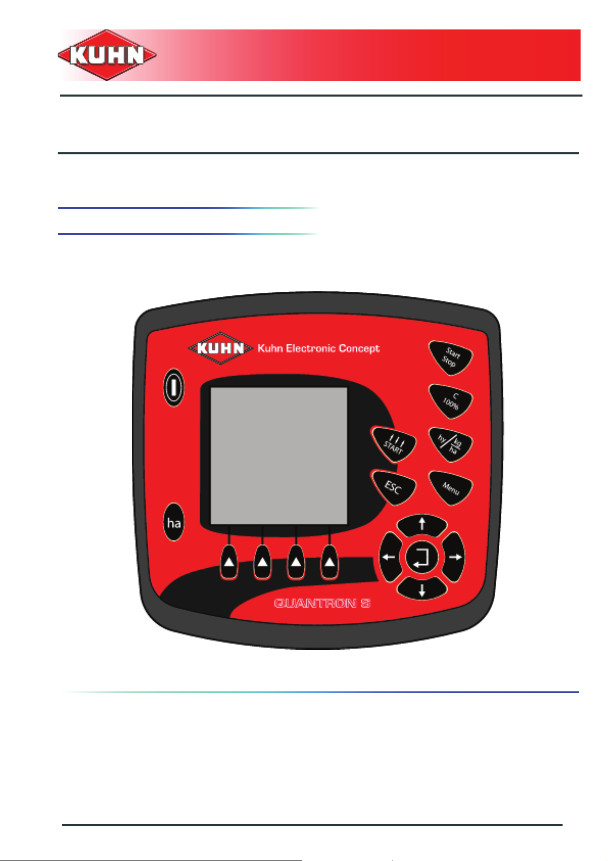
1. Front view
Control box
Quantron S
$Control box identification
Control box identification
5
Page 8

2. Manufacturers' marking
Please write below the type and serial number of the
machine.
This information is to be indicated to the dealer for all
spare parts orders.
Type: QUANTRON S
Serial no.:
Software version:
Control box
Quantron S
6
Control box identification
Page 9
$Safety
1. Description of symbols used in this
document
This symbol indicates a potentially hazardous situation
that if not avoided, could result in serious bodily injury.
Control box
Quantron S
This symbol is used to identify special instructions or
procedures which, if not followed strictly, could result in
machinery damage.
This symbol is used to communicate technical
information of particular interest.
Safety
7
Page 10

Control box
Quantron S
2. Safety instructions
Introduction
The operator must follow the safety instructions in this manual and in the machine's operator's manual as well
as respect the warnings posted on the machine.
Any use other than the designated operation is at the risk and responsibility of the operator.
The manufacturer is not held liable for any damage or accident resulting from machine modifications carried out
by the operator himself or by a third party without previous written agreement from the manufacturer.
8
Safety
Page 11

Read and follow the safety instructions
Before using the control box, carefully read all safety
instructions in this manual. The operator must be familiar
with all machine controls and their respective functions.
It is too late to learn once work has been started!
Never let anyone operate the machine who is not trained
to do so.
Should you have any difficulties in understanding certain
parts in this manual, please contact your KUHN dealer.
Precautions to take before using the
control box
Place the control box so that it cannot interfere with other
tractor controls and be activated inadvertently.
Before switching the control box on, check that nobody
is within the machine pivoting area: switching on the
control box can activate functions on the machine.
Control box
Quantron S
Precautions to take when using the control
box
Do not operate the control box while a person is carrying
out work on the machine.
Switch off control box before carrying out any
maintenance or repair work on the machine.
Precautions when driving
Before transporting the machine on public roads, make
sure no function of the control box or of the control
accessories can be switched on inadvertently.
Safety
9
Page 12
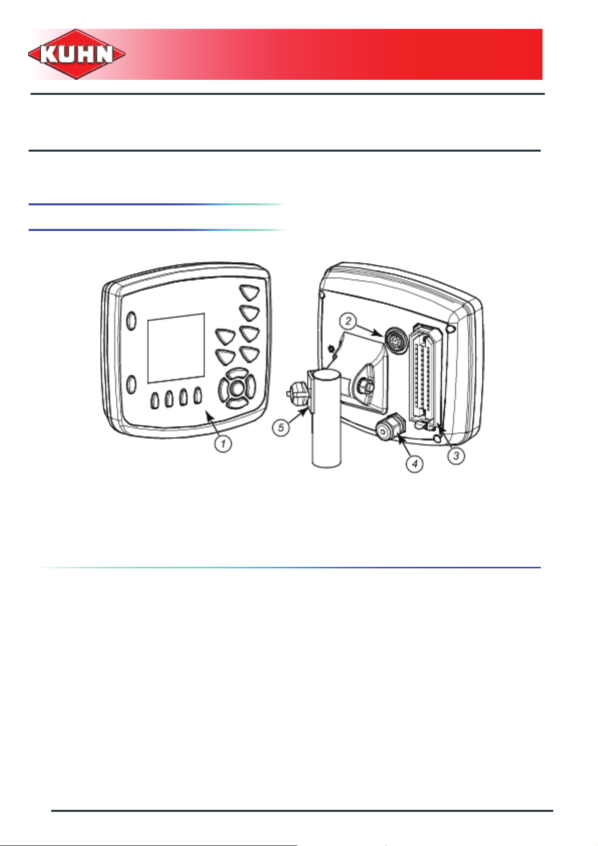
1. Description
0
Control box
Quantron S
$General description
1 : Area of use
2 : Connection pin for data transfer
3 : 39-pin connector: machine wiring harness connection
4 : Power circuit
5 : Holder: 2 x M8
10
General description
Page 13

2. Technical specifications
Operating temperature from -10°C to +60°C
Storage temperature up to +85 °C
Voltage input 12V, range from 10 V to 16 V
Shockproof plastic box, IP65 protection
classification
Screen 160x 160 pixels
CE certification
Control box
Quantron S
22 mm tube holder
Buzzer
Voltage
Maximum intensity
Sound level
Sound frequency
12 V
standby: 250 mA, in service: 15 A
120 dB
from 1.5 to 4 kHz
General description
11
Page 14
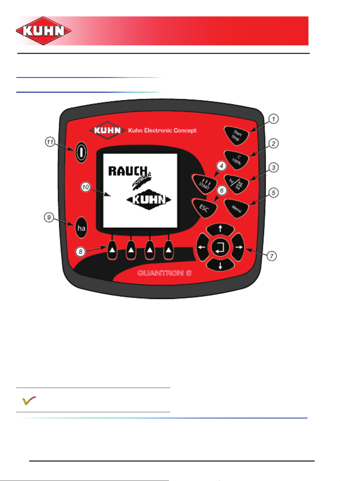
3. Description of control elements
Control box
Quantron S
0
1 : Distribution stop/start 2 : Delete / rollback
3 : Switch between the display of the application
rate and the display of the hydraulic valve bank
4 : Rollback to the tramlining counter
position
functions
5 : Access to the general menu 6 : ESC key
7 : Navigating keys with confirmation key 8 : F1 to F4 function keys
9 : Daily counters 10 : Display
11 : On/Off switch 0
When used in MANUAL mode, key Start/Stop is
not operational.
12
General description
Page 15
Display
The screen displays information relative to the current
machine status, with the possibility to select of modify
the values.
The main information relative to the machine's use are
displayed during work.
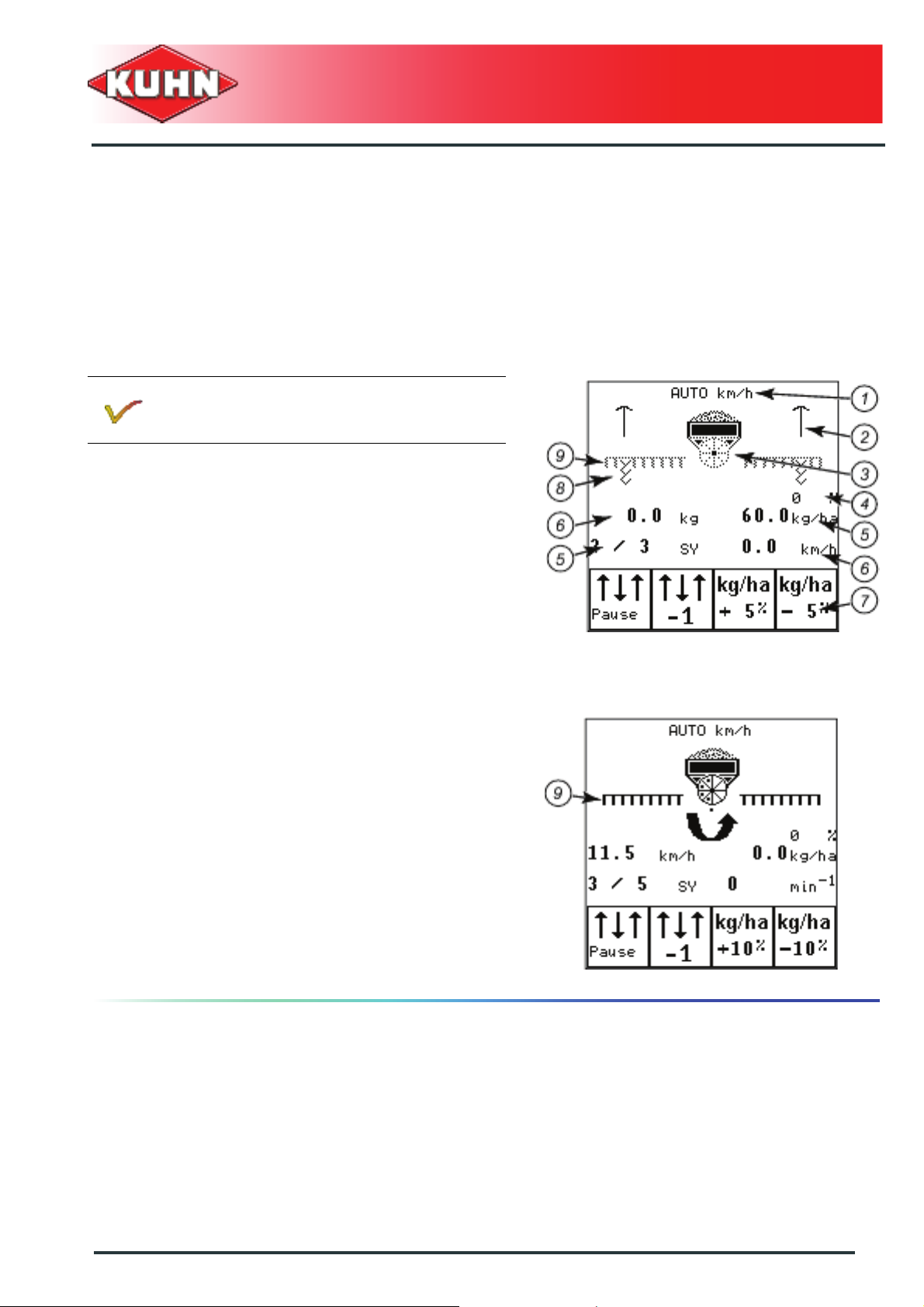
Description of screen zones
The precise definition of the work screen
varies according to the currently set
adjustments.
Meaning of symbols:
- Mode selection (1): Definition of the work mode used.
• AUTO km/h uses the speed signal of the radar or
the wheel impulse sensor.
• Man Km/h: Using the manual mode
The manual working mode can be used for ex. if the
speed sensor is faulty.
- Markers (2)
- Metering unit and hopper (3)
- Application rate adjustment (4)
- Screen areas that can be parameterized at will (6)
- The 2 other zones (5) always display the tramlining
rhythm and the seed application rate.
- Function area (7): the symbols displayed depend on
the machine configuration
• Access to these functions by selecting the function
placed below
- The tramlining (8): The paths for tramlining are being
made.
- Coulter bar (9):
• The work screen shows the coulter bar in a dotted
line. This symbol indicates that the coulter bar is
lowered but not sowing.
• The work screen shows the coulter bar in bold. The
coulter bar is in working position and sowing.
• The coulter bar does not appear on the screen. The
coulter bar is raised.
Control box
Quantron S
General description
13
Page 16
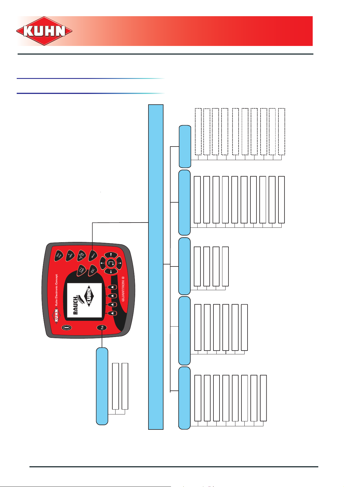
4. Menu structure
Control box
Quantron S
Main menu
Info
Low level sensor
Mach. width (m)
Languages
Choose new file Brightness / Contrast
Create new file
Hydraul. Block
DOSING mode
Tramlining actuat.
Test / Diagnosis
Display configurat.
Delete file
Delete all files
Signal tramlin.
Date
Time
Traml. width
Calibration flap
Data transmission
Total data counter
Alarm configuration
Imp./100 m.
Service
Alarm configuration
14
General description
Trip counter
Area test
Delete trip counter
Seed settings Hopper configuration Field data System / Test
Tramline rythm
Blower speed
Seed list factor
Tramlining
Seed list privat
Seed name
+/- appl. Rate (%)
Working mode
Machine (km/h)
Appl. (kg/ha)
Workingsp. (km/h)
Fine seed slide
Calibration start
Opening (mm)
Page 17
$Assembly and fitting
1. Tractor requirements
Before connecting the control box, make sure the tractor
complies with these conditions:
- Minimum voltage: 12 V: must be ensured even if
several systems are in service (Air conditioning,
Lighting).
Control box
Quantron S
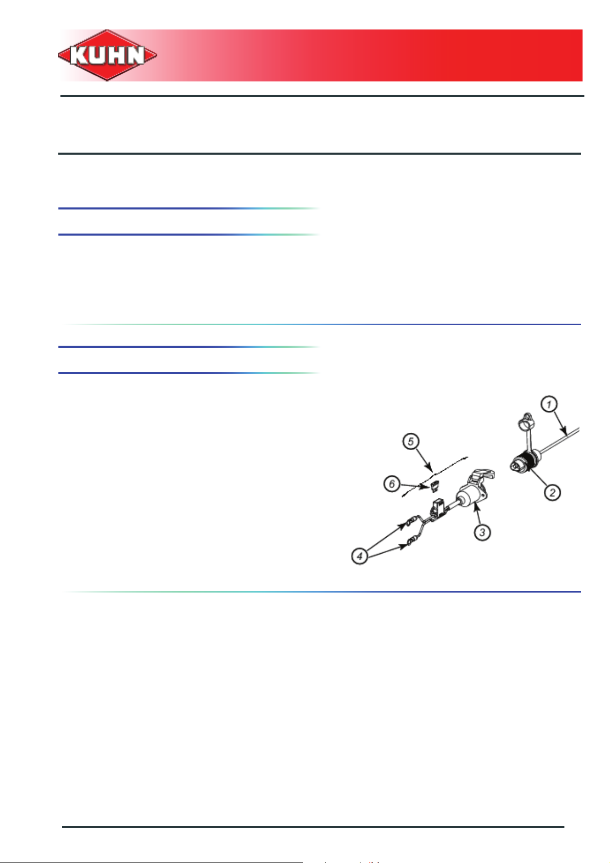
2. Electrical connection
The control box kit comprises:
- A wiring harness (1) pre-assembled on the box with a
male connector (2).
Electrical power supply
An electric power supply cable for another tractor can be
ordered under code 83233002.
The cable is connected by the Kuhn dealer to the plus
lugs (brown) and the tractor battery earth (blue).
For a regular and constant electricity supply for the
machines' controls, connect the electricity power cable
directly to the battery.
Assembly and fitting
15
Page 18

On tractor's fitted as standard with a 3-pin
plug, check the wire polarity to avoid causing
damage to the control box
- Make sure to avoid friction or crushing areas when
installing the power cable.
Control box power supply is from the tractor 3-pin
auxiliary power supply.
3. Control box connection
Carry out following tasks in the given order:
- Fit the control box in a position where the driver can
see it in the tractor cab.
- Connect the machines' 39-pin cable.
- Connect the control box to the power supply (See
chapter Electrical power supply).
Control box
Quantron S
The Quantron S control box is factory set for
the machine supplied.
Only connect the supplied control box to the
concerned machine.
16
Assembly and fitting
Page 19
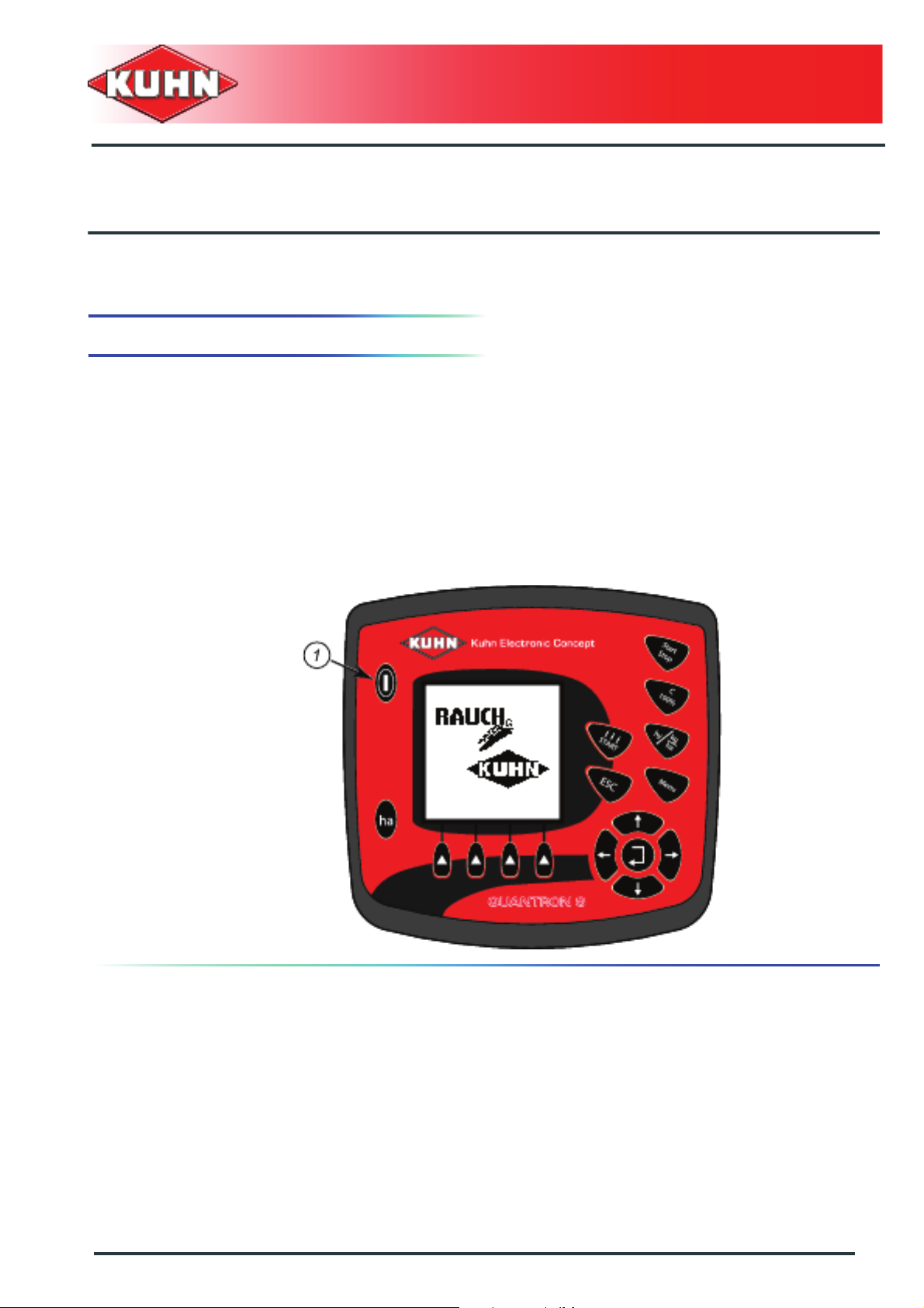
$Putting into service
1. Switches on the control box
Preconditions:
- The control box is properly connected to the tractor.
- Minimum voltage: 12 V
- Press Quantron S control box Start/Stop button (1).
- The start screen appears after a few seconds.
- A start menu is displayed during a few seconds.
- Then the work screen appears.
Control box
Quantron S
Putting into service
17
Page 20
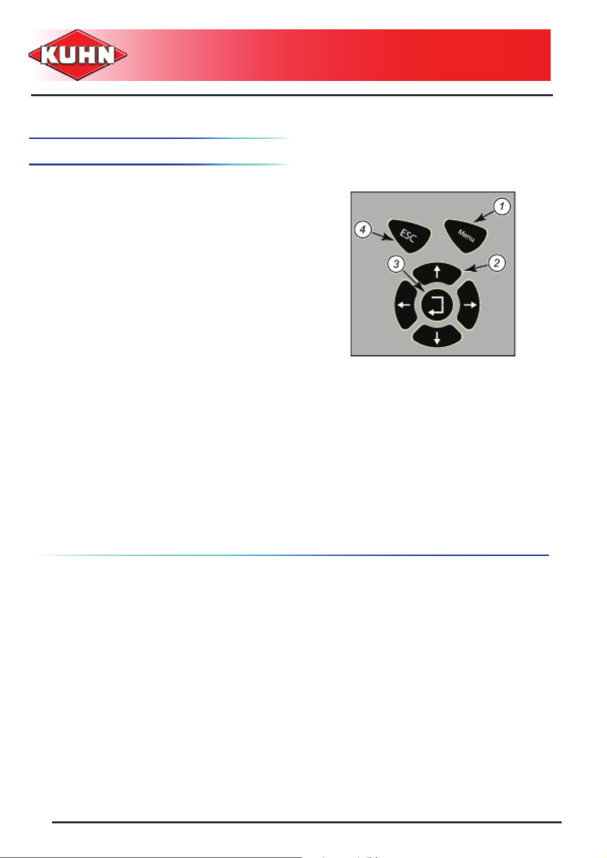
2. Access and menu navigation
MENU key (1)
- From the work screen, is used to access the menu
(see menu tree structure).
- From the menu, is used to return directly to the work
screen.
Warning: a value which was being changed will not be
recorded.
Displays current operations (2)
- "Up" or "+" key
• Used to select the previous line in the menu
• Used to increase a value being changed
- "Down" or "-" key
• Used to select the next line in the menu
• Used to decrease a value being changed
Control box
Quantron S
ENTER key (3)
• Used to select a submenu
• Used to record a modified value and return to the
previous screen
ESC key (4)
- Used to return to the previous screen
Warning: a value which was being changed will not be
recorded.
18
Putting into service
Page 21
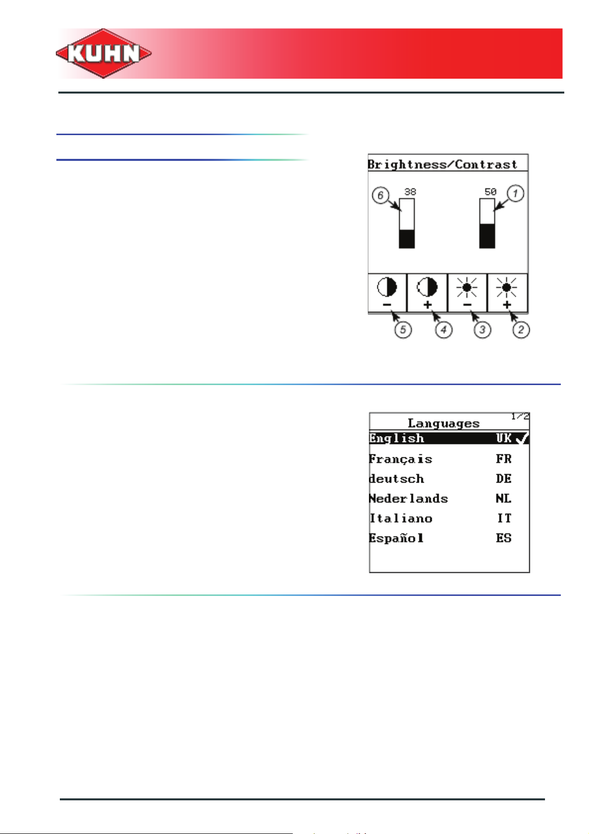
3. Basic adjustments
Basic adjustments are set in the "System/Test" menu.
Brightness/Contrast
- Press on the button «F3 (-)» (3), to reduce the
brightness (1).
- Press on the button «F4 (+)» (2), to increase the
brightness (1).
- Press on the button «F1 (-)» (5) to reduce contrast (6).
- Press on the button «F2 (+)» (4) to increase
contrast (6).
Control box
Quantron S
Language
There are 12 different languages available to navigate in
the control box menus.
- Select the "Language" submenu.
Page 1 out of two appears on the screen.
The other languages are listed on page 2/2.
- Move downwards using the arrow key until page 2/2
appears.
- Choose country language.
- Confirm your choice by pressing Enter key.
The control box comes ON again. The menus are
displayed in the new language.
Putting into service
19
Page 22
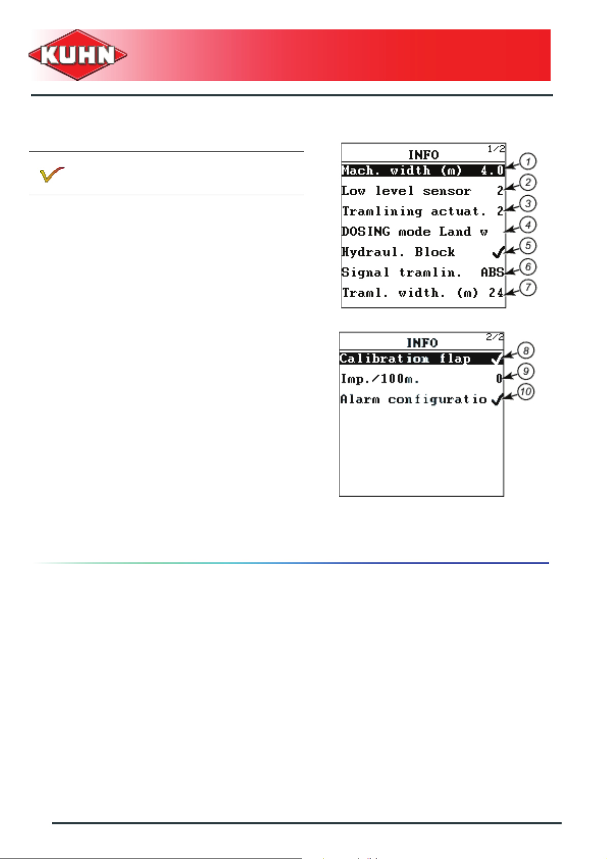
Info
This menu is only used for information purposes.
The menu shows how the machine is equipped.
- 1: Width of seed drill (m)
- 2: Number of low level sensors mounted (1 or 2)
- 3: 2 Cylinder for tramlining: The machine is fitted with
a second cylinder for tramlining.
• Symmetrical and asymmetrical rythms are possible.
- 4: Metering unit drive:
• Electrical drive
• Hydraulic drive
• Mecanical drive through a skeleton wheel
A check mark at the end of the line indicates that this
option is mounted.
- 5: Hydraulic valve bank: The control box is connected
to the hydraulic valve bank.
- 6: Signal for tramlining:
• ABS: The sensor on the chassis or on the coulter
bar counts the impulses for the tramlining counting
• SPR: The side marker sensor controls the tramlining
counting
- 7: The tramlining (m): Treatment width
- 8: Metering unit hatch sensor
- 9: Programmed impulses per 100 m length
(Calibration of forward speed)
- 10: Alarm configuration: A check mark on each line
end means that all alarms are ON.
Control box
Quantron S
20
Putting into service
Page 23
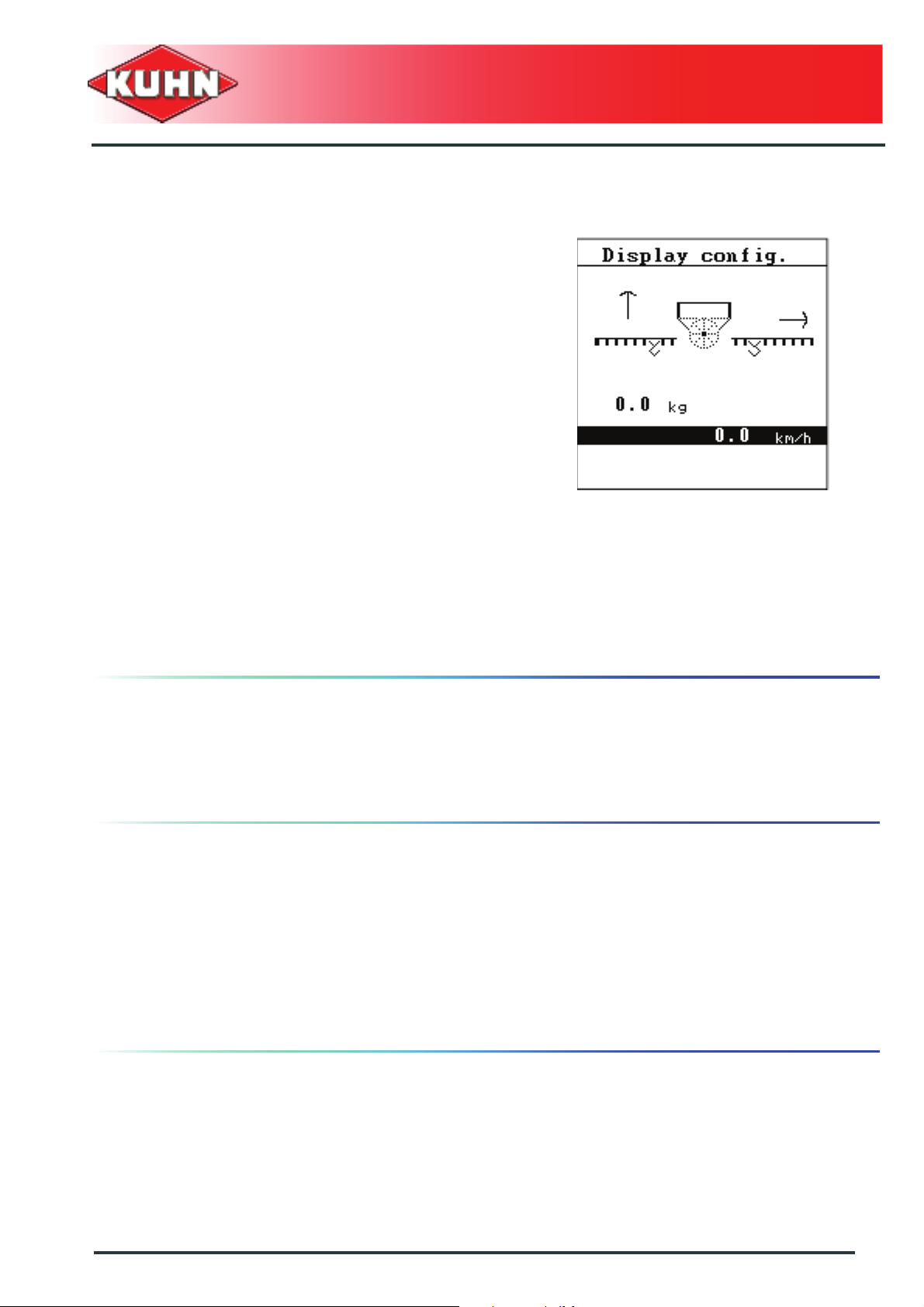
Display configuration
The screen has 2 free display areas. Following values
can be displayed:
- Working speed (Km/h)
- Blower speed
- Metering unit "opening position"
-Time
-Area
- Quantity sown "kg trip"
- Distance covered "m-trip"
- Metering unit rotation speed (min-1)
- As from the "System - Test" menu, select the "display
config" submenu.
- Select the screen area to modify.
- Validate using Enter key.
The list with the functions available appears on the
screen.
- Select the required function that will have to appear.
- Confirm your choice by pressing Enter key.
The screen will now display the required function.
Control box
Quantron S
Date/Time
The date and time are factory set.
If necessary, these parameters can be modified in the
"System - Test" menu.
Field data
This menu, accessible under "System - Test", displays
the following data:
- Quantity sown (independently from the seed variety)
- Area sown (2)
- Number of work hours
- Surface covered
Data displayed cannot be modified or deleted.
Putting into service
21
Page 24

Specific functions
Text entry (Example: seed name)
Some menus enable creating a name.
0
Control box
Quantron S
1 : Entry area 2 : Fully deleting a name
3 : Keys for navigating in the letter area 4 : Key for confirming the letter entry
5 : Function key (OK) for confirming the selected
name and return to the previous menu
6 : Navigation keys in the name entry
area
7 : Area with letters available for printing (depends
on the language)
22
Putting into service
Page 25

Modifying a letter:
- Select the letter in area (1) and position the cursor
using keys (6).
- Using arrow keys (3), move the cursor on the letter
selected in the letter area (7).
- Press Enter key.
The selected letter is positioned in the name creation
area. The cursor moves to the right of one space.
- Repeat procedure until name is completed.
- Press on function OK (5).
The text is memorized in the control box. The screen
displays the previous menu.
Replacing a letter:
An isolated letter can be replaced by another. Deleting
an isolated letter is not possible.
Fully deleting a name:
- Press on the button C/100%.
- Press on function OK.
Control box
Quantron S
Entering values using the arrow keys
Certain menus enable entering numerical values
(Example: Volume).
To move cursor (1), use right and left arrow keys.
Enter the required digit using the vertical arrows:
- Upward arrow: Increasing the selected value.
- Downward arrow: Reducing the value selected.
- Confirm entry by pressing Enter key.
Software updating
Software updating can only be performed by
authorized persons.
Putting into service
23
Page 26

$Machine use
1. Adjustments before first use
Read the operators' manual before using the
machine.
- Make sure that all requested options are set on the
machine.
Proceed with the various pre-controls and adjustments
indicated in the operators' manual.
- Couple the machine to the tractor.
- Check if the electrical power cable of the control box
is connected.
- Check the connection between the machine 39-pin
wiring harness and the control box.
- Switch on the control box.
Control box
Quantron S
- Starting from the "main menu", select "hopper
configuration".
- Select the "Machine km/h" submenu.
- Check machine name.
24
Machine use
Page 27

2. Calibration of forward speed
Factors such as spinning or soil condition can influence
the forward speed measuring and consequently the
application rate.
- Calibrate the speed sensor for 100m to take sowing
conditions into account.
The speed sensor calibration is based on the count of
the sensor impulses over a distance of 100 m.
- Starting from the "main menu", select "hopper
configuration".
- Select the "Machine km/h" submenu.
The speed signal can come from the tractor, the radar
sensor or a wheel sensor.
- Select the speed source:
• F2 (4): Tractor radar
Connect the speed plug wiring harness on one end to the
7-pin plug on the rear of the control box and the other to
the tractor 8-pin plug (DIN9684-1,ISO11786).
Part no. 2056323
• F1 (5): Drill radar or Wheel mounted impulse sensor
When driven mechanically, the travel speed is
indicated by the metering unit sensor.
- Press on function F1 (5).
Control box
Quantron S
Do NOT press F2 (4) if the metering unit is
mechanically driven.
Machine use
25
Page 28

If the number of impulses is known, it can be entered
by hand.
- Select the "Machine km/h" submenu.
- select Imp/100m (2).
- Press Enter key.
- Enter the number of impulses. See chapter Entering
values using the arrow keys.
• Average value for VENTA NC 3000/4000 (Wheel
diameter 400 mm): 970 Imp/100 m
• Average value for MEGANT: 1000 Imp/100 m
• Average value for MODULINER and Radar:
900 Imp/100 m
• Average value for the front hopper; For machines
with serial number as from 11612:
13260 Imp/100 m
- Press Enter key.
If the number of impulses is unknown, proceed with
calibration.
Control box
Quantron S
The calibration must be carried out in the field.
Reference trip: 100 m
- Select the "Machine km/h" submenu.
- Press on function F4 (Auto).
The calibration screen appears.
At the beginning of the reference trip:
- Press key F1 below START (3).
The counter is reset. The control box is ready to count
the impulses.
- Cover 100 m.
At the end of the reference trip:
- Stop moving forward with the tractor.
- Press key F4 below STOP (2).
The number of pulses is displayed on the screen (1).
- Press Enter key.
The new number of impulses is memorized. The screen
displays the previous menu.
26
Machine use
Page 29

3. Preliminary adjustments at work
Working mode
Drilling can be carried out in MANUAL or AUTOMATIC
mode.
The normal working mode is the AUTOMATIC mode.
The manual working mode can be used for ex.
if the speed sensor is faulty.
- Starting from the "main menu", select "hopper
configuration".
- Select the "working mode" submenu.
- Select the required working mode.
- Press Enter key.
Control box
Quantron S
Application rate adjustment
During work, the application rate can be adjusted in
percentage (in addition or deduction) if the conditions
require it (soil condition,...) (See chapter Metering unit
display).
Setting the adjustment rate
This function is only accessible on hydraulically
or electrically driven machines.
The 100% basis is the opening value for the metering
unit.
- Starting from the "main menu", select "hopper
configuration".
- Select the "+/- appl." submenu.
- Enter the percentage rate for adjusting the
application rate during work. See chapter Variation of
the seed rate.
- Press Enter key.
Machine use
27
Page 30

Adjusting the blower alarm limit values
- Starting from the "main menu", select "hopper
configuration".
- Select the "blower speed" submenu.
- Select value (1).
- Press Enter key.
- Indicate the minimum speed alarm value (see table for
values).
- Press Enter key.
- Select value (2).
- Press Enter key.
- Indicate the maximum speed alarm value (see table
for values).
It is very important to maintain the correct blower
rotational speed.
- According to the seed drill type, values are different!.
Control box
Quantron S
Normal use speeds
Minimum
speed
LC 302-452 3600 4500 4250
NC
3000/4000
Small grain
Large grain
Moduliner-
Solo
TF 702
Small grain
Large grain 2800 3500 3200
MEGANT 2800 3500 3200
Respect the indicated values. In case of
excessive speed, there are risks of damaging
the machine.
2700 3300 3000
3500 4500 4200
2800 3500 3200
2000 2800 2500
Maximum
speed
Nominal
speed
28
Machine use
Page 31

Tramlining rhythm
Setting the tramlining rhythm according to the wheel
track and the treatment width.
- Starting from the "main menu", select "hopper
configuration".
- Press Enter key.
- Selecting the "tramlining" sub-menu.
- Press Enter key.
- Select the "Trav.alley rhythm" submenu (1).
- Enter the treatment width.
- Validate using Enter key.
The screen displays the previous menu.
The control box displays the various rhythm possibilities.
If the machine is only fitted with one
tramlining control cylinder: only symmetrical
rhythms are possible.
Control box
Quantron S
Example 1
With a treatment width of 28 m, the control box
calculates the SY 7 rhythm (2).
Drilling starts with the rhythm in position 4 (3).
- Drilling start with the total seed drill width (4).
The field edge can be to the right or left
when using odd symmetrical rythms
(SY3,SY5,SY7,SY9,SY11).
If the drilling start is made with the total seed drill
width, the field edge can be to the right or left.
Example 2: Symmetrical rhythm
With a treatment width of 24 m, the control box
calculates the SY 6 rhythm (2).
Drilling starts with the rhythm in position 3 (3).
- Shut-off the left half-width at the beginning of the
field (4).
The field edge can be to the right or left
when using odd symmetrical rythms
(SY3,SY5,SY7,SY9,SY11).
If the drilling start is made with the total seed drill
width, the field edge can be to the right or left.
Machine use
29
Page 32

Example 3: Asymmetrical rhythms
- Press on function F2 (6).
- With a treatment width of 24 m, the control box
calculates the AS 6 rhythm (2)
Drilling starts with the rhythm in position 4 (3).
Select the field edge side to start drilling using
keys F3, F4 (5).
- Drilling start with the total seed drill width (4).
Control box
Quantron S
Tramlining
This menu is established to set the tramlining.
On headlands, the counting for the tramlining is only
possible if a continuous signal from the sensor is
emitted.
• Press Enter key.
• Indicate the time delay required after which the
tramlining counting is accepted.
Choice of where the signal comes from:
• ABS (3): The sensor on the chassis or on the coulter
bar counts the impulses for the tramlining counting.
A time delay of 2 to 5 is recommended.
-
• SPR (2): The side marker sensor controls the
tramlining counting.
The time delay can be set to 0.
- (4): Choice of tramlining correction on working screen.
See chapter Tramlining rhythm adjustment.
30
Machine use
Page 33

4. Stationary calibration test
Before loading the seeds and carrying out the
flow test, set the metering unit in the position
adapted to the seed variety (small or large
seeds).
Select type of seed
- As from the "main menu", select the "seed settings"
submenu.
- Select "Seed list Factory " sub-menu (1).
- Press Enter key.
A list comprising 14 seeds is stored in
alphabetical order.
Control box
Quantron S
- Select the required seed variety.
If the required seed is not included in the Factory
list, select a seed with similar specifications
(Seed weight, Volume).
For small and large seed mix (ex. oat and grass
mix) to seed at low application rate,
we recommend to use the Grass seed < 25kg in
the Factory list.
For maize, select a variety with a high Thousand
Grain Weight. Required application rate:
minimum 22 kg/ha.
- Press Enter key.
The selected seed will be saved in the "PRIVATE" list.
The screen displays the previous menu.
The control box indicates the required metering
unit outlet or small seed slide position.
- For small seeds, the "small seed" slide must be
positioned by hand in the metering unit (3).
Values relative to this seed variety are stored in the
"PRIVATE" list.
Machine use
31
Page 34

- If needed, change the seed name.
• Select the name line (2).
• Press Enter key.
We recommend to rename the seed to
differentiate the various seeds stored.
Control box
Quantron S
32
Machine use
Page 35

Volume
- Select the "Appl. (kg/ha)" submenu.
- Press Enter key.
- Enter the required application rate using
the arrow keys. See chapter Entering values using the
arrow keys, Page 23.
- Confirm entry by pressing Enter key.
Working speed
Control box
Quantron S
- Select the "working (km/h)" submenu.
- Indicate the planned working speed.
- Press Enter key.
This entry is not possible if the metering unit is
mechanically driven.
Machine use
33
Page 36

Carry out the calibration test
The metering unit opening is set to determine the density
of seeds sown.
Carry out regular calibration tests to check that
the seed drill is properly adjusted.
Carry out the calibration test with the
machine lowered, the power take-off
disengaged and the tractor stopped.
Carry out the calibration test:
• Before drilling
• If the seed quality is modified (humidity, dust,
impurities)
• When the seed variety is changed
Control box
Quantron S
- Move browser down to position yourself on the "Test
start" sub-menu.
- Press Enter key.
- Open the seed drill metering unit to the value
indicated.
- Position a container under the metering unit to collect
the seeds.
- Press Enter key.
34
Machine use
Page 37

- Shortly rotate the metering unit in order to fill the cells.
- Press on the button Start/Stop.
On machine driven hydraulically or electrically,
the metering unit will automatically rotate by one
turn to fill the cells.
- Empty the container and reinstall it underneath the
metering unit.
- Press Enter key.
- Press on the button Start/Stop.
- Rotate metering unit by at least 30 turns.
If necessary, the test can be stopped (e.g. to
empty the container before it overflows), and
resumed using Start/Stop key.
• After 30 metering unit rotations, a short sound alarm
will resound. This minimum quantity is required to
accept the calibration test.
The minimum quantity is reached. The seed flow can be
stopped.
Control box
Quantron S
Wheat: Rotate metering unit by at least 50 turns.
Rape: Rotate metering unit by at least 100 turns.
The screen displays:
• Number of metering unit rotations
• Distribution cylinder rotation speed
• The number of metering unit rotations required
to simulate the application rate corresponding to
1/10 ha
- Press on the button Start/Stop.
- Press Enter key.
- weigh the seeds collected during the test.
- Input collected weight.
- Press Enter key.
Machine use
35
Page 38

The control box calculates the new opening required and
displays it on the screen.
- Adapt metering unit opening according to the value
displayed on the screen (See corresponding manual).
In most cases, it is not necessary to adjust the
metering unit opening, as the electric or
hydraulic drive adjusts the rotation speed.
- Press Enter key.
- Shut-off the calibration flap.
- Press Enter key.
Control box
Quantron S
The calibration test is accepted. Settings will be stored in
the Private list under the saved name.
- Press Enter key.
The machine is ready for work.
If a new calibration test is required, repeat
procedure with the new metering unit opening.
36
Machine use
Page 39

Proceed with a new calibration test
After presetting the metering unit opening, run a
calibration test to know the exact density of
seeds.
- Select the "Seed settings" sub-menu.
- Press Enter key.
- Move browser down to position the cursor on the
"Optimize and calibrate" sub-menu.
- Follow screen instructions.
- Proceed with a new calibration test. See chapter
Carry out the calibration test, Page 34.
Control box
Quantron S
5. Modification of the parameters
A modification of the planned application rate or work
speed of an already calibrated seed requires
confirmation.
- Select values to modify and validate each
modification.
- Select the "Seed settings" sub-menu.
- Press Enter key.
Machine use
37
Page 40

The screen displays:
• Metering unit "opening position"
• Required small seed slide position
• Minimum and maximum application rate values
• Minimum and maximum travel speed values
Accept
- If the possible working zones (outlined values) are
convenient, confirm by selecting "Accept".
- Press Enter key.
The regulation adapts the application rate or speed
modification by means of the drive speed. The new
opening is identical to the former one.
Optimizing the working zone
Control box
Quantron S
If the working zones (outlined values) must be optimized,
there are two possibilities.
Optimize
- Select "Optimize".
- Press Enter key:
• The control box calculates the new opening
required and displays it on the screen.
• According to the application rate or travel speed
modification, the control box will suggest a new
optimized working zone.
- Adapt metering unit opening according to the value
displayed on the screen (See corresponding manual).
- Press Enter key.
38
Machine use
Page 41

The calibration test is accepted. Settings will be stored in
the Private list under the saved name.
- Press Enter key.
- The machine is ready for work.
Optimize and test
- Select "Optimize and test".
- Press Enter key.
• The control box calculates the new opening
required and displays it on the screen.
• According to the application rate or travel speed
modification, the control box will suggest a new
optimized working zone.
- Proceed with a new calibration test. See chapter
Carry out the calibration test, Page 34.
Control box
Quantron S
6. Flow test with regards to an area
For this function, a seed flow for a set area can be
simulated.
- Press on the button ha.
- Select "Area test" sub-menu.
- Press Enter key.
Machine use
39
Page 42

- Choose test area using the corresponding key.
• Example: F2 for 1/10 ha
- Position a container under the metering unit to collect
the seeds.
- Press Enter key.
- Press on the button Start/Stop.
If necessary, the test can be stopped (e.g. to
empty the container before it overflows), and
resumed using Start/Stop key.
Control box
Quantron S
The metering unit rotates until the set theoretical area
is reached.
The metering unit stops automatically.
- Weigh the container and deduct the container weight
(tare) in order to know the quantity collected for the
area of reference used.
- Compare the collected seed quantity with the
instructions in the "Seed settings" menu.
If the quantity collected varies with regards to
the required application rate, proceed with a new
calibration test.
- Press Enter key.
- Shut-off the calibration flap.
- Press Enter key.
40
Machine use
Page 43

7. Sowing a seed already stored
When selecting a seed already stored, the screen
displays the latest values stored.
- As from the "main menu", select the "seed settings"
submenu.
- Select the "Seed list privat" sub-menu (1).
- Press Enter key.
- Select the required seed variety.
The screen indicates the values stored with this seed:
• Dose per hectare
• Work speed in km/h
• Required small seed slide position
- Select the "Seed settings" sub-menu.
- Press Enter key.
Control box
Quantron S
The screen displays:
• Metering unit "opening position"
• Required small seed slide position
• Minimum and maximum application rate values
• Minimum and maximum travel speed values
Accept
- If the possible working zones (outlined values) are
convenient, confirm by selecting "Accept".
- Press Enter key.
If the working zones (outlined values)must be optimized,
there are two possibilities:
• Optimize
• Optimize and test
See chapter Modification of the parameters, Page 37.
Machine use
41
Page 44

8. Deleting a seed
A seed stored in the "Seed list privat" can be deleted in
the following cases:
• The "Seed list privat" is full.
• The seed will no longer be sown.
- As from the "main menu", select the "seed settings"
submenu.
- Select the "Seed list privat" sub-menu.
- Press Enter key.
- Using the browser, select the seed to delete.
- Press on function F2 (1).
The seed will be deleted.
Control box
Quantron S
42
Machine use
Page 45

$Functioning during work
1. Distribution stop/start
- Lower the marker and the coulter bar.
Sowing start
- Start metering unit in the following situations:
• Sowing start
• Power on.
- Press on the button Start/Stop.
The metering unit will run for 6 seconds in a premetering
function.
If the tractor starts to move forward during these
6 seconds, the machine will automatically switch into
work application rate.
If the tractor moves forward at a speed of less than
1,5 km/h, the application rate is stopped.
Control box
Quantron S
The metering unit only starts if following
conditions are met:
- The machine is in working position
- The blower rotates
- The calibration flap is closed.
- The low level sensor indicates the
presence of seed inside the hopper.
- The minimum blower speed is exceeded
(1,5 km/h).
Impulse mode
In automatic mode, the metering unit automatically stops
when lifting and starts when lowering the drill.
The metering function on the headlands is controlled by
the working position sensor (ABS).
Functioning during work
43
Page 46

Drilling in field corners
To maintain the seed quality in the corners, use the
premetering function.
- Press 2 times Start/Stop key.
The metering unit will run for 6 seconds in a premetering
function.
Move forward with the tractor while premetering is
running.
Momentary drilling stop
- Press button Start/Stop in the following situations:
• At the end of work
• Filling the hopper.
Press Start/Stop button when seeding should
start again.
Control box
Quantron S
Using the manual mode
In the manual mode (MAN km/h), the premetering is
impossible. The programmed speed is the reference
speed.
Respect the reference speed during work.
Otherwise over and underdosing will occur.
- Press on the button Start/Stop.
44
Functioning during work
Page 47

Stopping tramlining temporarily
The button "Pause" avoids that the counting is continued
whilst going around an obstacle.
Condition: the working screen must be displayed.
- Press key F1 (1) (REST).
If the seed drill is fitted with a circuit selector:
- Press on the button hy: The screen displays the
hydraulic selector functions.
- Press on function F3 (1) : Confirm the marker lift
function.
- After goind round the obstacle, press key F3
Lower marker and coulter bar.
Control box
Quantron S
- Press key F1 (2) (REST).
The tramlining counting will continue. Quantity and
distance counting will carry on.
Functioning during work
45
Page 48

2. Hydraulic valve bank
Functions available For Speedliner
3000/4000/6000.
- Press on the button hy: The screen displays the
hydraulic selector functions.
Functions not activated:
• (1): The side markers can be controlled by the
tractors' hydraulic outlet.
• (2): The preparation tools can be lowered or raised
using the tractors' hydraulic valve
Control box
Quantron S
Functions activated (Black background):
• Roller pressure (1)
• Hydraulic roll folding (2)
46
Functioning during work
Page 49

Functions available for the BTFR coulter
bar
- Press on the button hy: The screen displays the
hydraulic selector functions.
• (1): Side marker control
• (2): Coulter bar control
White background: Functions not activated
Black background: Markers (1) and coulter bar (2) can
be operated.
Control box
Quantron S
3. Tramlining rhythm adjustment
The tramlining rhythm can be modified by hand if
necessary.
Condition: the working screen must be displayed.
- Use key F2 (1) until correct rhythm position is
obtained.
The correction direction for the tramlining is adjustable in
the menu "tramlining" under "Machine Configuration".
See chapter Tramlining.
Functioning during work
47
Page 50

4. Operating data
This menu is used for saving data of 200 fields.
- As from the "Main menu", select the "Field data"
menu.
Data can be saved either in field file already saved
(resuming work that had been stopped) or by creating a
new file.
Creating a new file (2)
- Select "Create new file".
- Press Enter key.
- Enter the field name in the allocated space.
The field name can be entered freely. See chapter
Text entry.
The number of letters is limited to 40.
Page 1 out of two appears on the screen.
Control box
Quantron S
Selecting a file (1)
Values saved in a file are not deleted, but completed with
new values.
- Select "Choose new file" submenu (2).
- Press Enter key.
The screen displays the field names saved in
alphabetical order.
- Select the required field.
- Press Enter key.
Page 1 out of two appears on the screen.
48
Functioning during work
Page 51

Starting field data
0
1 : Display of the number of files still available
2 : Submenu used for starting the field data
3 : Identification area
4 : Values saved
5 : Display of date and time of drilling start
6 : Display of date and time of drilling end
7 : Display of the seed name used
8 : Submenu used to delete values saved in a file
- Select the "Field data start" submenu (1).
- Press Enter key.
The data recording starts.
The working screen displays the cassette symbol during
the field file recording (9).
Control box
Quantron S
Stopping the recording
- As from the "Field data" menu, enter the file currently
used.
- Select the "Field data stop" submenu.
- Press Enter key.
The file recording is stopped.
Functioning during work
49
Page 52

Deleting one or several files
Deleting a file:
- As from the "Field data" menu, select the "Delete file
data" submenu.
- Press Enter key.
- Select the file to delete in the list
- Delete the file by pressing Enter key.
The screen displays the previous menu.
Deleting all files
- As from the "Field data" menu, select the "Delete all
files" submenu.
- Press Enter key.
A buzzer sounds. An alarm message appears.
- Validate using START key.
- Press on the button ESC: all files will be deleted.
Control box
Quantron S
5. Variation of the seed rate
During work, the application rate can be adjusted using
keys F3/F4. See chapter Application rate adjustment.
Key C/100% cancels the adjustment and the normal
application rate restarts.
Use during work:
- Press on function F3: The normal applicartion rate is
increased by the programmed adjustment rate.
- Press on function F4: The normal applicartion rate is
decreased by the programmed adjustment rate.
• The applied variation of seed rate is indicated above
the seed rate (1).
50
Functioning during work
Page 53

6. Daily counters
- Press on the button ha.
The screen displays:
- Quantity sown (independently from the seed
variety) (1)
- Area sown (2)
- Surface covered (3)
since the last reset.
Deleting the daily counter (4)
- Move browser downwards to select the "Delete trip
counter" sub-menu.
- Press Enter key.
All daily counter values are reset.
- Press on the button ha.
Deleting the daily counter values does not affect the
field data files.
Control box
Quantron S
Functioning during work
51
Page 54

$System/Test
1. Sensor check
The "Test/diagnosis" menu monitors and indicates the
status of the machine sensors or actors.
This menu is only used for information purposes.
- As from the "System - Test" menu, select the "Test diagnosis" menu.
- To choose the desired function.
Control box
Quantron S
The list of sensors depends from the machine
equipment. Following sensors are controlled by the
control box.
- Blower sensor/Working position sensor
- Metering unit sensor,
- Metering unit hatch sensor:
• Sensor is deactivated: The calibration flap is closed
- Low level sensors (UP/DOWN)
- The power supply
- Tramlining: Position of tramlining motor (Left, Right)
-Markers
• Sensor is deactivated: Markerarm is lifted
- Power harrow sensor
• Sensor is deactivated: Power harrow rotating. The
sensor controls the rotation of the power harrow.
- Electric motor
52
System/Test
Page 55

Example: Metering unit
0
1 : Sensor short circuit (Function not switched on)
2 : Wire cut
3/4 :
Sensor function area
3 : Sensor is deactivated
4 : Sensor is activated
Control box
Quantron S
Example: Electric motor
- Press on the button F1 (2) and keep it pressed down.
When the electric motor rotates, the power supply is
represented by the black bar.
System/Test
53
Page 56

2. Alarm configuration
The submenu Alarm configuration allows to deactivate
following sensors if they are broken. The machine can
continue to work.
• Blower
• Calibration flap
• Low level sensors (UP/DOWN)
• Power harrow sensor
Only the sensors which are mounted and
stored in the menu "Machine options" are shown
on the screen. See chapter Service: Machine
configuration
- Uncheck the box corresponding to the faulty sensor:
Press Enter key.
Control box
Quantron S
Replace broken sensors as soon as possible.
Reactivate the required alarm configuration.
54
System/Test
Page 57

$Service: Machine configuration
1. Service
The configuration of the control box through the
"Service" menu is required in following situations:
• New options are mounted on the machine.
• Old or broken equipment are removed.
• The control box is used on several machines.
The "Service" menu under "System-tests" requires a
password to avoid accidental changes of factory
settings.
Control box
Quantron S
Contact your authorised Kuhn dealer to get
the password.
- (1): The Quantron S control box is factory set for the
machine supplied.
- (2): This menu is reserved and accessible only by a
KUHN technician.
- (3): Access to factory settings menu
• Press Enter key.
• Save: The options installed by the user are stored.
The factory adjustments will be rewritten. The
previous machine settings will no longer be
possible
• Recreate: The previous programmed machine
settings can be reinstalled.
- (4): The values stored in the total counters are reset.
Service: Machine configuration
55
Page 58

2. Machine options
Check the equipments mounted on the drill,
before changing values in the menu
"Machine options".
Wrong entries may influence the working
quality and even provoke damage the
machine.
Contact your authorised Kuhn dealer to get
the password.
(1) Identification area: Check machine name.
- Press Enter key.
- Enter new designation.
(2): Width of seed drill (m)
- Press Enter key.
- Enter machine width.
(3): Number of low level sensors mounted
- Press Enter key.
- Enter number of sensors.
(4): One or two tramlining motors are mounted
• Press Enter button to select one of the 2 possible
values.
(5): Power harrow sensor
• A check mark at the end of the line indicates that this
option is mounted.
(6): Not used
(7): Metering unit drive:
- Press successively key Enter to select the functioning
mode.
• Electrical drive
• Hydraulic drive
• Mecanical drive through a skeleton wheel
Control box
Quantron S
56
Service: Machine configuration
Page 59

Move downwards using the arrow key until page 2/2
appears.
(1) Check width of mounted metering unit.
- There are 2 values possible: 150 mm or 200 mm.
- Press Enter button to select one of the 2 possible
values.
A check mark at the end of the line indicates that this
option is mounted.
(2): Hydraulic valve bank: The control box is connected
to the hydraulic valve bank.
(3): Metering unit hatch sensor
(4): Side marker sensors
(5): Enter the serial number of the machine connected to
the control box.
(6): Programming the theoretical number of pulses
(without slippage) of the metering unit sensor for a travel
of 100 m. This value is only used with seed drills fitted
with a mechanically driven metering unit
- Enter value depending on machine type:
Control box
Quantron S
VENTA EC
VENTA LC
SPEEDLINER
Radar
Working
width (m)
impulse/100m
(Distribution
sensor)
3750
3 750
3,5 875
4 1000
4,5 1125
3 1290
41280
6 1290
Service: Machine configuration
57
Page 60

$Alarm messages
When an anomaly is detected, an alarm screen is
displayed and a permanent buzzer sounds.
1. Alarm signification
Control box
Quantron S
Nr. Error messages
1 Fault in metering unit!
2
3
4 Volume outside limits
5
Maximum application rate reached!!
Forward speed or metering volume too high
Minimum application rate reached!
Forward speed or metering volume too low
Description
• Possible causes
• The metering unit does not rotate
although the machine is lowered.
Alarm only possible on machines driven by an
electric or hydraulic motor
• The maximum motor speed has been
reached.
Alarm only possible on machines driven by an
electric or hydraulic motor
• Forward speed or metering volume too
low.
• The quantity collected does not reach or
exceeds by 20 % the theoretical value to
collect.
Only on machine with a low level sensor
• Hopper empty
6
7
58
Alarm messages
Data is deleted!
Delete = START
Abort = ESC
Only on machine with 2 low level sensors
• Right hopper empty
Alarm message for preventing inadvertent
deleting of all data
Page 61

Control box
Quantron S
Nr. Error messages
8
9 Blower speed too high
1
0
1
1
1
2
1
3
Forward speed or metering volume too high
1
4
1
5
1
6
Blower speed too low
Pre-metering stopped
Data transfer error
No RS232 connection
Desired weight outside limits
max. 20 km/h
Calibration flap not closed
Memory full
Deletion of a private table
Description
• Possible causes
Only on machine with 2 low level sensors
• Left hopper empty
• The blower exceeds the maximum
authorized speed value.
The alarm disappears automatically if the
speed decreases below the maximum
authorized speed value.
• The blower does not reach the minimum
authorized speed value.
The alarm automatically disappears when the
speed exceeds the minimum authorized
speed value.
Alarm only possible on machines driven by an
electric or hydraulic motor:
• The pre-metering is activated by pressing
the start/stop key but the blower has not
reached the minimum authorized speed
value.
Alarm only possible on machines driven by an
electric or hydraulic motor:
• The pre-metering is stopped and there
was no forward signal sent before 5
seconds.
• A fault has occured during the data
transfer towards/as from the control box
• The maximum and minimum alarm values
depend on the seed variety.
• The speed value is hoo high for calibration
test.
• The flap is still in calibration test position
and the blower is rotating.
• The maximum number of 46 seed
adjustment charts has been reached.
Alarm messages
59
Page 62

2. Deleting a breakdown or an alarm
An alarm on the screen is simultaneously combined with
a sound alarm.
Deleting an alarm
Look for the cause, and do what is needed.
Refer to the seed drill operator's manual.
- Press on the button C/100%.
The alarm disappears.
Control box
Quantron S
60
Alarm messages
Page 63

$Trouble shooting guide
-
Problem Cause Remedy
The electric or hydraulic drive
rotates non stop during the
calibration test.
The electric or hydraulic drive
does not rotate during
calibration test.
Irregular rotation of the electric
or hydraulic drive
The control box does not receive
the rotation sensor signal.
The stored machine options are
incorrect (Mechanical metering
unit drive).
The rotations pulses are not
properly picked up.
Sowing has been stopped.
The hopper is empty
- Verify the distance between the sensor
and the tips of the metal teeth on the
pinion.
- Replace sensor.
- check current settings using INFO
menu.
- Check control box programming.
- Adapt if necessary.
- Verify the distance between the sensor
and the tips of the metal teeth on the
pinion.
- Press on the button Start/Stop.
- Start sowing using key Start/Stop after
having started the control box.
- Reconfigure alarm condition of the
seed level sensors.
Control box
Quantron S
When sowing, the metering
unit electric or hydraulic drive
does not start.
The electric or hydraulic motor
continues rotating when
turning round.
Incorrect speed is memorized - Adjust blower speed.
- If the blower sensor is faulty, do not
Faulty blower rotation sensor
Coulter bar or power harrow not
lowered
Calibration flap not closed - Shut-off the calibration flap.
No speed signal
Faulty speed sensor
Faulty work position sensor
forget to deactivate it in the "diagnostic
menu".
- Check work position sensor on the
frame or coulter bar.
- Check speed signal source.
- The speed signal can come from the
tractor, the radar sensor or a wheel
sensor.
- Select the "Machine km/h" submenu.
- Select the speed source.
- The manual working mode can be
used for ex. if the speed sensor is
faulty.
- Check work position sensor on the
frame or coulter bar.
Trouble shooting guide
61
Page 64

Problem Cause Remedy
- Check the power connection
The pre-emergence marker
solenoid valve does not
function.
The tramlining rhythm is not
counted.
Bad connection
The PAUSE key has been
activated.
The marker manoeuvre does not
affect the tramlining counting.
Faulty side marker sensor
- Connect wire marked L of wiring
harness Y to the solenoid valve.
- The wire marked R of wiring harness Y
must be connected to a second
solenoid valve for special rhythms.
- Press key F1 (REST).
- The pulses for tramlining are sent by
the wrong sensors.
- In the "tramlining" sub-menu of the
"Hopper configuration" menu, activate
counter on SPR (markers).
- Test the sensors using the diagnosis
menu.
Control box
Quantron S
62
Trouble shooting guide
Page 65

$Maintenance and storage
The control box does not require any particular
maintenance, in the case of a breakdown or a
malfunction call your KUHN technician.
For any welding operation on the machine,
disconnect the electricity supply of the
machine and the tractor (battery and
alternator).
When cleaning the machine, never point the
water jet on the control box.
Control box
Quantron S
Maintenance and storage
63
Page 66

E-M otor
R2055972
Control box
Quantron S
$Connecting diagrams
Sponrad
Landwheel
R2056714
Kabel
R2056569
Roue squelette
L= Links- gauche - left
Wire
Câble
N
Allgemein – En général – Generally
O
R = Rechts – droit - right
MEGANT
VENTA NC
R2055842
Aktuator rechts
Actuator right
OPTION
Kabel
R2055838
Vérin électrique droit
Wire
Câble
Hy-Bloc
Hy-Block
R2055148
Traceur de prélevée
Vorauf laufma rkierung
Pre-emergence marker
E-Drive
Moteur électr ique
R2055148
Trémie
Hopper
Bloc hydraulique
Fullstand
R2055637
N
OPTION
O
DAT
VAM
HYD
LMR
FMR
KMH
R2055844
FML
GEB
SPL
SPR
DOS
LML
ABS
DOK
KEG
O
N
Wire
Kab el
Câble
R2055838
R2055848
64
Connecting diagrams
Geblä se
R2055639
Trémie
Doseur
Turbine
Fan unit
R2055638
R2055639
Dosiereinheit
Metering system
R2055639
Spuranreißer
Side markers
Arbeitsstellung
Traceurs latéraux
Hopper
Fullstand
R2055637
Frame position
Position chassis
R2055842
Aktuator links
Vérin électrique G
Injektor
Injector
Injecteur
Actuator left
R2055639
Kreiselegge
R2055639
Power ha rrow
Herse rotative
Page 67

E-M otor
R2055972
Control box
Quantron S
Bloc
Hy-Bloc
Hy-Block
hydraulique
R2055148
Sponrad
Landwheel
R2055639
Roue squelette
Trémie
Hopper
Fullstand
R2055637
E-Drive
Moteur électr ique
R2055848
EC 3000
OPTION
R2055639
Arbe itsste llung
Frame position
Position chassis
SPEEDLINER
Wire
Kabel
Câble
R2055838
N
O
HYD
ABS
DAT
LMR
KMH
R2055047
SPL
R2055639
Spuranreißer
Side markers
Traceurs laté raux
R2055845
KEG -
FML6 -
FML2 -
VAM
KEG +
FML7 -
FML8 -
SPL -
VAM -
SPR -
SPL +
SPR +
FML3 -
FML4 -
SPR
FML5 -
FML5 +
FML6 +
FML7 +
FML8 +
VAMR +
R2055846
FML1 +
FML2 +
FML3 +
FML4 +
VAML +
FML1 -
LML
GEB
DOK
DOS
L= Links- gauche - left
R = Rechts – droit - right
Gebläse
R2055639
Allgem ein – En général – Generally
R2055047
Trémie
Turbine
Fan unit
R2055638
Injektor
Doseur
Injecteur
R2055639
Dosiereinheit
Me terin g system
Hopper
Injector
Fullstand
R2055637
R2055148
Vorauflaufmarkierung
Traceur de prélevée
Pre-emergence marker
R2055639
Spuranreißer
Side ma rkers
Traceurs latéraux
Connecting diagrams
65
Page 68

R2055839
Kab el fü r Prop Ve ntil
Control box
Quantron S
Bloc
Hy-Bloc
Hy-Block
hydraulique
R2055148
R2055639
Arbe itsste llung
Frame position
Position chassis
Trémie
Hopper
Fullstand
R2055637
Wire for p rop. valve
Câble pour valve prop.
RADAR
DICKEY-JOHN
R2055848
MODULINER 1
SPEEDLINER 1
OPTION
SPL
R2055639
Spuranreißer
HYD
Side markers
Traceurs latéraux
N
Adapter
Adaptateur
R2055841
O
DAT
LMR
KMH
R2055047
ABS
R2055845
KEG -
FML6 -
FMR2-
VAM
KEG +
FML7 -
FML8 -
SPL -
VAM -
SPR -
SPL +
FMR3-
FMR4-
SPR +
SPR
FML5 -
FML5 +
FML6 +
FML7 +
FML8 +
VAMR +
FMR1+
FMR2+
R2055846
LML
GEB
DOK
DOS
FMR1-
FMR3+
FMR4+
VAML +
66
Connecting diagrams
Gebläse
R2055639
L= Links- gauche - left
R = Rechts – droit - right
Allgem ein – En général – General ly
Trémie
Turbine
Fan unit
R2055638
Injektor
Doseur
Injecteur
R2055639
Dosiereinheit
Me terin g system
Hopper
Injector
Fullstand
R2055637
R2055047
R2055148
Vorauflaufmarkierung
Traceur de prélevée
Pre-emergence marker
R2055639
Spuranreißer
Side ma rkers
Traceurs latéraux
Page 69

R2055839
Kabel für Prop Ventil
Control box
Quantron S
R2055639
Spuranreißer
Side markers
R2055047
FMR3+
FMR4+
FMR3 -
FMR4 -
SPR -
SPR +
FMR1+
FMR2+
R2055847
FMR1 -
FMR2 -
Trémie
Hopper
Fullstand
R2055637
Wire f or pr op. va lve
Câble pour valve prop.
Adaptateur
R2055841
RADAR
DICKEY-JOHN
N
Adapter
O
R2055848
R2055148
OPTION
Bloc
Hy-Bloc
Hy-Block
hydraulique
R2055639
Arbeit sste llun g
Frame position
Position chassis
R2055047
Traceurs latéraux
SPR
DAT
Geblä se
R2055639
LMR
KMH
HYD
ABS
VAM
R2055845
R2055047
LML
R2055638
Dosiereinheit
DOK
DOS
Trémie
Doseur
R2055639
Met ering system
Hopper
Injektor
Injector
Injecteur
Fullstand
R2055637
GEB
Turbine
Fan unit
FML3 +
FML1 +
R2055847
R2055148
Voraufla ufma rkierung
FML4 +
FML2 +
Traceur de prélevée
Pre-emergence marker
FML3 -
FML4 -
SPL -
SPL +
FML1 -
FML2 -
SPL
L= Links- gauche - left
R = Rechts – droit - right
All gemein – En général – General ly
R2055639
Spuranreißer
Side markers
Traceurs latéraux
67
SPEEDLINER 2
R2055047
MODULINER 2
Connecting diagrams
Page 70

Fullstand
R2055637
Control box
Quantron S
Sponrad
Landwheel
R2056714
Roue squelette
Trémie
Hopper
Hy-Block
R2055148
Bloc
Hy-Bloc
hydraulique
E-Drive
E-M otor
R20564 30
Moteur électr ique
R2055848
OPTION
VENTA TF + BTF
Adapter
Adaptateur
R2056723
N
O
DAT
LMR
KMH
R2055047
R2055639
SPL
R2056041
KEG -
FML5 -
FML5 +
FML6 +
FML7 +
FML8 +
VAMR +
KEG +
FML6 -
FML7 -
FML8 -
HYD
Spuranreißer
Side ma rkers
Traceurs latéraux
68
Connecting diagrams
GEB
Gebläse
R2055639
SPL -
VAM -
SPR -
FMR1-
FMR1+
FMR2+
FMR3+
R2055846
DOS
Turbine
Doseur
Fan u nit
R2055638
R2055637
Dosiereinheit
Me terin g system
DOK
LML
Trémie
Hopper
Fullstand
ABS
R2055639
Arbe itsste llung
L= Links- gauche - left
R = Rechts – droit - right
Allgem ein – En général – General ly
Frame position
Positio n cha ssis
R2055047
FMR2-
FMR4+
VAML +
VAM
R2055148
Traceur de prélevée
Vorauflaufmarkierung
SPL +
FMR3-
FMR4-
SPR +
SPR
R2055639
Spuranreißer
Side ma rkers
Traceurs latéraux
Pre-emergence marker
Page 71

$Limited warranty
Control box
Quantron S
Limited warranty
69
Page 72

Control box
Quantron S
70
Limited warranty
Page 73

Page 74

Page 75

Page 76

 Loading...