

Page 1
PZ 320C
Operatio n ma nual
Issue 04/2009
Date of printing 7.2009
Language EN
From machinenumber (PIN) VGLP000010
Serial number (PSN) 01LP01
Reference number ZNA032EN
Page 2

Identifica ti on of the m achine
To support you as soon as possible your dealer requires several details of your machine.
Please enter the information here.
Designation
PIN
Software version
Assembled
options
Dealer's address
PZ 320C
VGLP.................................
Manufacturer's
address
KUHN-GELDROP B.V., retains all copyrights and rights of usage. The contents of this operating manual are subject to change without notice. All
rights reserved. The right to technical revision is reserved.
KUHN-GELDROP B.V.
Nuenenseweg 165
5667 KP Geldrop
The Netherlands
Phone +31 40 2893300
Page 3

Table of contents
Preface..............................................................4
Target group of this operation manual 4
Symbols used 5
Safety instructions ..........................................6
For your safety 6
Safety decals at the machine 7
Who is allowed to operate the machine? 10
General 10
Hitching the machine 11
Weight and ballasting determination 12
Hydraulics 15
Road transport 16
Working with the machine 17
Unhitching the machine 19
Care and maintenance 20
Further prescriptions 21
Warranty 22
Table of contents
Preparation at the field ................................. 40
Safety 40
Performing settings 40
Prior to mowing 40
Placing into working position 41
Cutting height adjustment 42
Ground pressure 43
Conditioner 44
Use at the field............................................... 46
Safety 46
Using the machine 46
Pto 46
Driving speed 47
Safety device 47
Headland driving 48
Incline driving 48
End of working 49
Acquaintance with the machine...................23
Destination of the machine 23
Characteristics of the machine 23
Description of the components 24
Technical specifications 25
Delivery and preparation ..............................27
Checking the delivery 27
Hitching the machine ....................................28
Safety 28
General 28
Lower link pins 29
Hitching to the 3-point hitch 30
Coupling the pto drive shaft 31
Connections 32
Preparation for use........................................34
Safety 34
General 35
Top and lower link adjustment 35
Hitching frame height 36
Running 36
Check at beginning of the season 36
Cleaning and caring ...................................... 50
Safety 50
Cleaning 50
After cleaning 50
Caring 50
Storing the machine...................................... 51
Safety 51
General 51
Unhitching and securing of the machine 51
Maintenance................................................... 53
Safety 53
General 55
Attaching elements 58
Tightening torques 59
Pto drive shaft 60
Lubrication 62
Blades 64
Moving / renewing blade holders 65
Gearboxes 67
Optional equipment....................................... 72
General 72
Road transport...............................................37
Safety 37
Before road transport 37
Placing into transport position 38
Road transport 39
Troubleshooting ............................................ 73
General 73
Disposal of the machine ...............................74
EC Declaration of conformity....................... 75
Index ............................................................... 76
3
Page 4

Preface
Preface
Target group of
this operation
manual
This operation manual is meant for those concerned with the control,
use and maintenance of the machine. It contains all data required for
a safe handling, use and maintenance of the machine.
For your safety
Before starting to adjust and use your machine, familiarise yourself
with this operation manual. By doing so your safety and the best
performance are assured. It is very important to read this manual
carefully before using the machine and to keep it handy. In this way,
you will
• avoid accidents
• respect the warranty conditions
• always have a functional machine in perfect working order
For the employer
All personnel are to be trained in the use of the machine regularly (at
least once a year) in accordance with employers’ liability insurance
association guidelines. Untrained or unauthorised individuals are not
permitted to use the machinery.
You are responsible for the safe operation and maintenance of your
machine. You must ensure that you and anyone else who is going to
operate, maintain or work around the unit be familiar with the
operating and maintenance procedures and related safety information
contained in this manual.
4
Page 5

Preface
Symbols used
In this operation manual the following symbols and terms are used:
• A bullet stands at enumerations
> A triangle stands at steps, which you must do
→ An arrow shows cross-references at other text passages
[+] The plus sign shows that it involves optional equipment, which
does not belong to the standard model.
Besides these symbols, pictograms are used, which will help you with
locating of text passages:
TIPThe word “Tip“ shows tips and advices to the use.
The triangle refers to danger at assembling or (adjusting) work.
The key refers to tips at assembling or adjusting work.
0
The star shows examples, which are needed for a better
understanding.
5
Page 6

Safety instructions
Safety instructions
For your safety
This chapter contains all general safety instructions. Subject-specific
safety instructions are located per chapter. Take care of the safety
instructions
• because of your own safety
• because of the safety of your fellow man
• to guarantee the machine safety
When handling agricultural machinery, wrong behaviour can lead to a
lot of danger. Therefore work with special care and never under
pressure of time.
For the employer
Inform the one who works with this machine frequently about these
safety instructions and according to the legal regulations.
6
Page 7
Safety instructions
Safety decals at
the machine
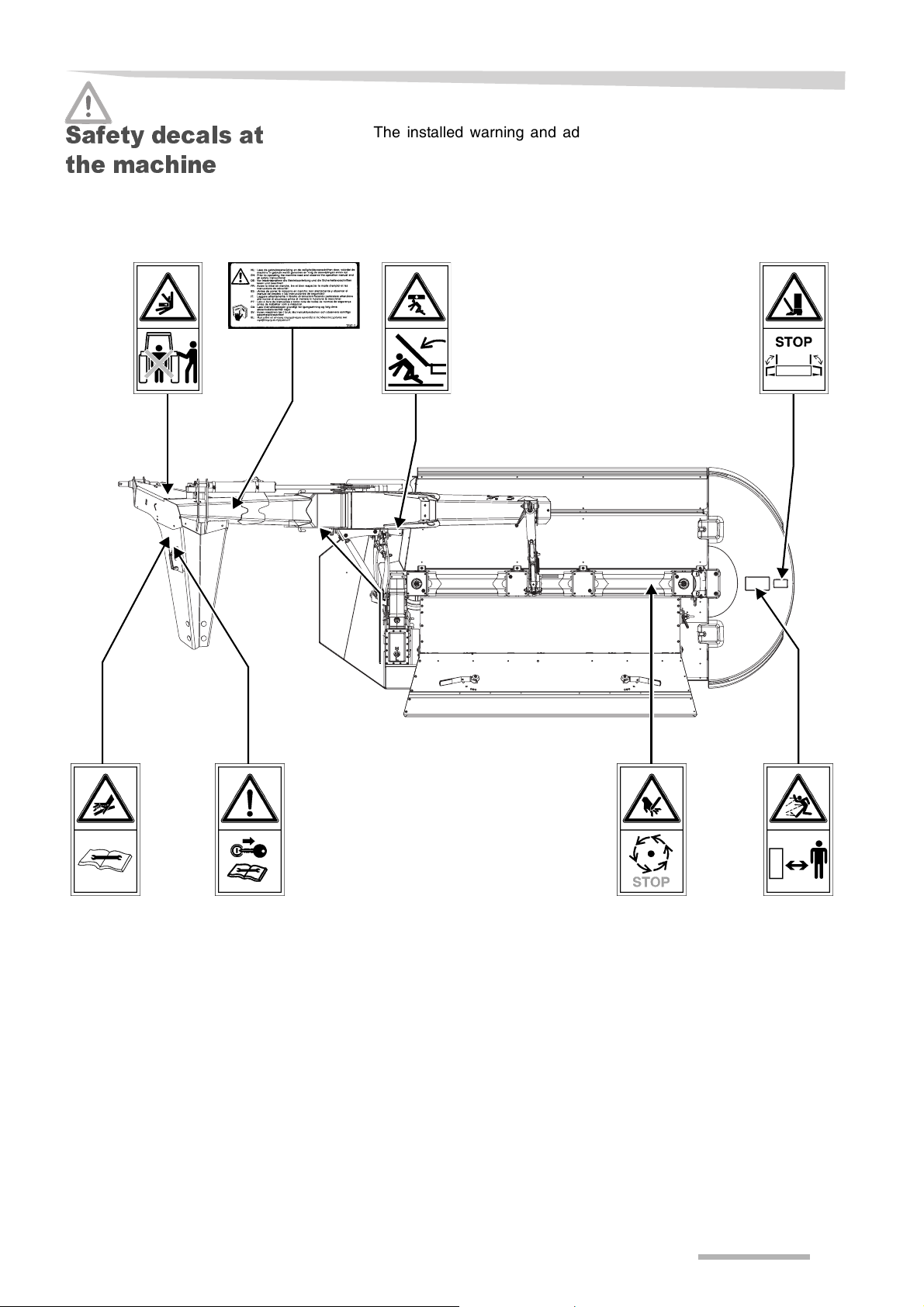
The installed warning and advisory signs give important hints for a
safe operation; adhering to serves your own safety. Keep safety
decals and signs clean and legible at all times. Replace safety decals
and signs that are missing or have become illegible. If original parts on
which a safety decal or sign was installed are replaced, be sure that
the replacement part also displays the current decal or sign.
7
Page 8
Safety instructions
Meaning of the safety
decals
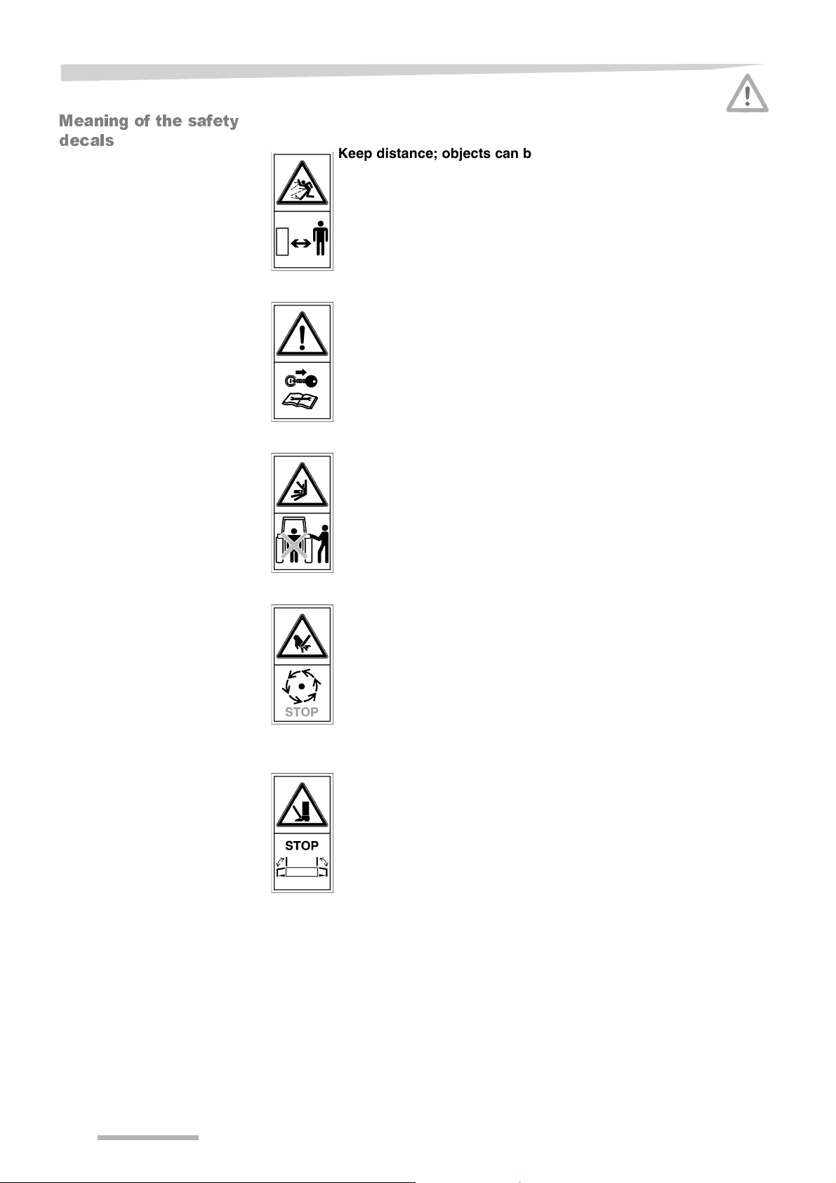
Keep distance; objects can be flung away at very high speed
Keep distance of the machine; objects, like stones and other debris,
can be flung away at very high speed (250 - 300 km/h). Serious or
deadly injuries can occur.
Shut off engine and remove key
Shut off engine and remove key before performing maintenance or
repeair work.
Do not stand between the tractor and the machine
During attachment/detachment of the machine, nobody shall stay
between drawbar and tractor. Serious personal injuries can occur.
Do not enter machine components before it has completely
stopped
Wait until all machine components have completely stopped before
touching them.
Do not move the shielding before complete standstill
Wait until all machine components have completely stopped before
entering the machine. Rotating knives can not be seen. Serious
injuries can occur.
8
Page 9

Safety instructions
Read the operation manual carefully
Read the operation manual carefully before taking the machine into
operation.
Do not find or stop a hydraulic leakage by hand
The hydraulic system is under high pressure. Never attempt to find or
even to stop a hydraulic leakage with your hands. High pressure fluid
easily penetrates skin and clothes, causing severe injuries: visit a
doctor immediately when injured.
Do not be situated below a lifted machine
A lifted machine must be adequately supported. A machine can sink
while being below or under it. A sinking machine can cause serious or
deadly injuries.
9
Page 10

Safety instructions
Who is al lo w e d to
operate the
machine?
General
Authorised people only
The machine may only be used, maintained or repaired by authorised
people who have been informed about the dangers when handling the
machine.
Usually such persons have an agricultural or equal intensive
education.
Safety is your responsibility
Apply and insist upon application of the safety instructions. Most
accidents are avoidable. Do not run the risk of serious or fatal
accidents through ignorance of these safety instructions.
Wear close fitting clothing
Avoid wearing loose fitting clothing.
Loose clothing can get stuck between rotating parts. Danger of
serious injury.
Keep the machine clean
Always keep the machine clean to avoid fire risk.
Fire extinguisher
Carry a fire extinguisher at all times, especially when operating in dry
crop materials. This should be a multi-purpose ABC rated extinguisher
with a 10 kg capacity, approved by the appropriate authority.
Use a proper tractor
Make sure the tractor is in safe operating condition with adequate
braking capabilities for a machine of this weight.
→ the tractors technical details
No running in a closed area
Do not run the machine in a closed area. Exhaust fumes collect
without being noticed. Exhaust fumes can cause serious or deadly
injuries.
Never work on a running machine
Never work on the machine while it is running. A running machine has
several moving parts which can not be seen. These moving parts can
cause serious injuries.
No modification of the machine
Do not modify the machine in any way. Unauthorised modifications
may impair the function and/or safety and could affect the life of the
machine. All warranty will be reduced to nil and void.
10
Page 11

Safety instructions
Hitching the
machine
Increased danger of injury
While hitching the machine onto the tractor an increased danger of
injury occurs. Therefore:
• prevent the tractor from rolling away, shut down the engine and
remove the ignition key
• never stay between tractor and machine during hitching
• mount and secure the pto drive shaft at the pto
In case of negligence damages to the machine or serious personal
injuries can occur.
Pto drive shaft operation manual
Regard to the operation manual of the pto drive shaft manufacturer.
Here you find instructions for correct handling of the pto drive shaft.
Negligence can lead to damages at the pto drive shaft and to the
machine.
Fix and check pto drive shaft protection
The rotating pto drive shaft is secured by a pto drive shaft protection.
Take care that the pto drive shaft protection is not damaged. Pto drive
shaft protection must be fixed through the chains, both at tractor and
machine side. Unprotected pto drive shafts can cause serious
personal injuries.
Maximum pto speed 1000 rpm
The prescribed pto speed of maximum 1000 rpm may not be
exceeded. Higher pto rpm can cause damages to the machine.
11
Page 12
Safety instructions
Weight and
ballasting
determination
Determination
Sources
Obey the maximum permissible weight, permissible axle loads
and tyre load carrying capacities
The mounting of machines to the front or to the rear 3-point linkage
shall not result in exceeding
• the maximum permissible weight
• the permissible axle loads
• the tyre load carrying capacities of the tractor
Also the front axle of the tractor must always be loaded with at least
20% of the unladen weight of the tractor.
The following needs to be determined:
• total weight
• axle loads
• tyre load carrying capacity
• the necessary minimum ballasting
For the determination you need data from the following sources:
• operation manual of the tractor
• operation manual of the machine [this operation manual]
• data, to be determined or calculated
Data from operati on
manual of the trac tor
A
B
C
Data from operati on
manual of the
machine
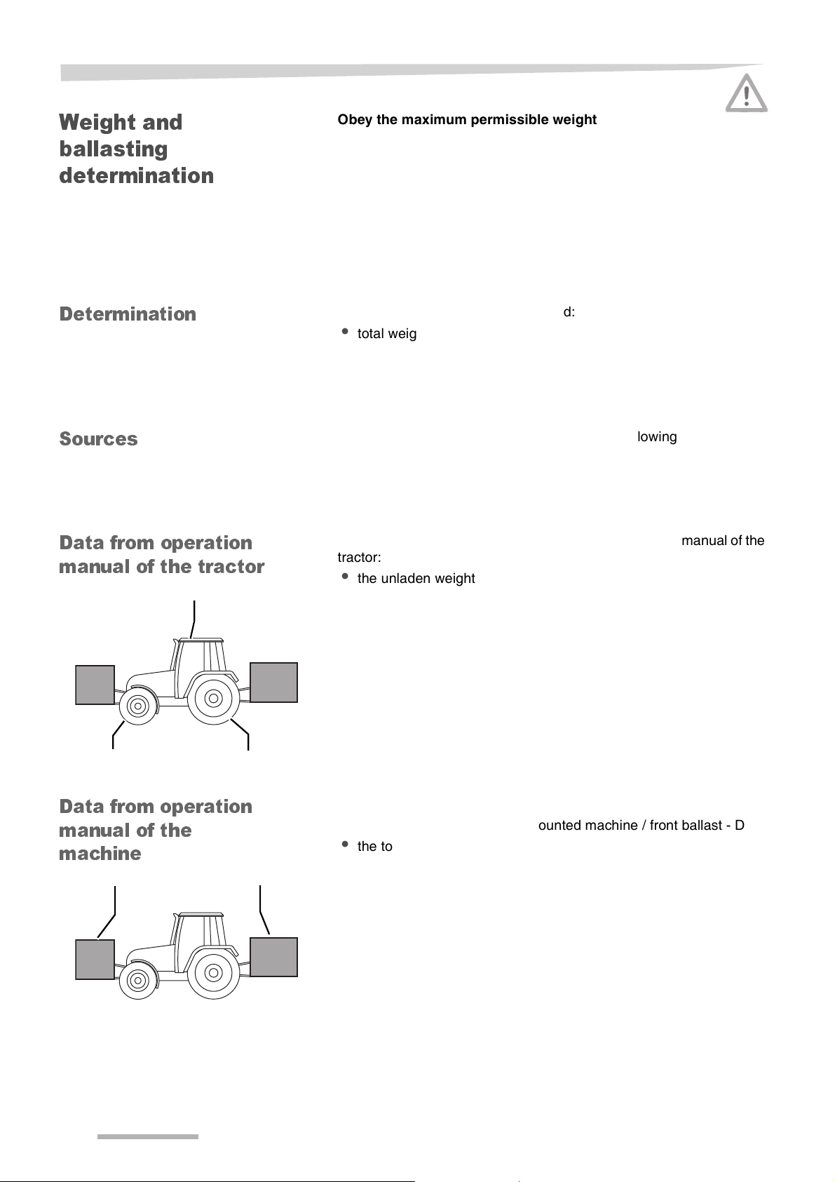
The following data must be extracted from the operation manual of the
tractor:
• the unladen weight of the tractor - A
• the front axle weight of the unladen tractor - B
• the rear axle weight of the unladen tractor - C
> Enter the values A until C in the table
→ »Table«, page 14
The following data must be extracted from this operation manual:
• the total weight of the front mounted machine / front ballast - D
• the total weight of the rear mounted machine / rear ballast - E
ED
12
Page 13
Safety instructions
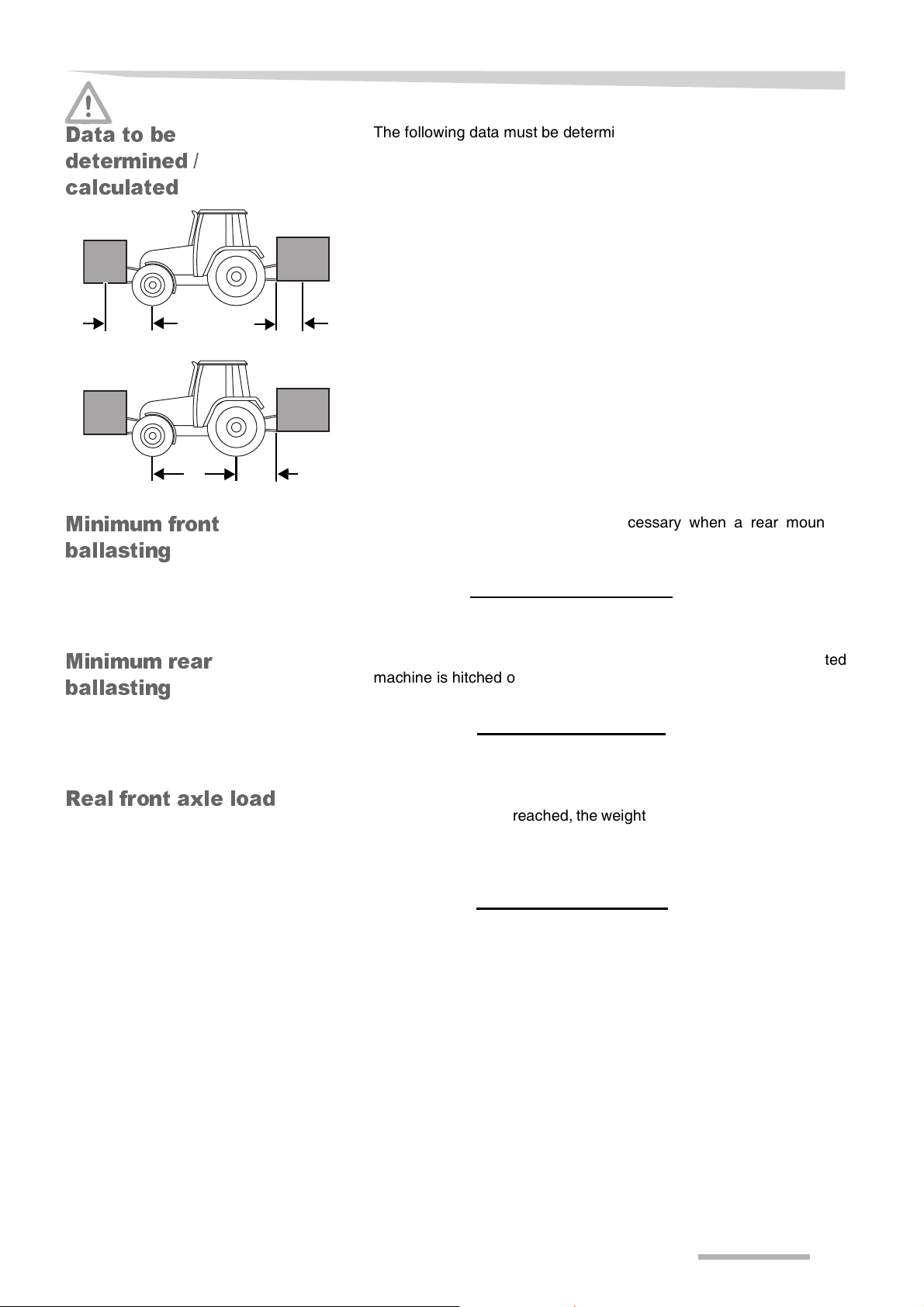
Data to be
determined /
calculated
F G
H I
Minim um front
ballasting
The following data must be determined / calculated:
• the distance from the centre of gravity for the combined front
mounted machine / front ballast to the front axle centre - F
• the distance from the centre of gravity for the combined rear
mounted machine / rear ballast to the rear axle centre - G
• the tractor wheelbase - H
• the distance from the rear axle centre to the centre of the lower link
balls - I
The minimum front ballasting is necessary when a rear mounted
machine is hitched onto the tractor.
The minimum front ballasting in kg is to be calculated as follows:
E x (I + G) - (B x H) + (0,2 x A x H)
F + H
= ........... kg
Minimum rear
ballasting
Real front axle loa d
The minimum rear ballasting is necessary when a front mounted
machine is hitched onto the tractor.
The minimum rear ballasting in kg is to be calculated as follows:
(D x F) - (C x H) + (0,45 x A x H)
H + I + G
If with the front mounted machine the required minimum front
ballasting cannot be reached, the weight of the front mounted machine
has to be increased to the weight of the minimum ballasting at the
front.
The real front axle load in kg is to be calculated as follows:
D x (F + H) + (B x H) - E x (I + G)
H
= ........... kg
= ........... kg
13
Page 14

Safety instructions
Real total weight
Real rear axle lo ad
Tyre load carryi ng
capacity
Table
Real value according to
calculation
If with the rear mounted machine the required minimum rear ballasting
cannot be reached, the weight of the rear mounted machine has to be
at least the weight of the minimum ballasting at the rear.
The real total weight in kg is to be calculated as follows:
D + A + E = ........... kg
The real rear axle load in kg is to be calculated as follows:
Real total weight - real front axle load = ........... kg
The tyre load carrying capacity is to be found in the documentation of
the tyre manufacturer.
Enter in the table:
> double the value for two tyres of the permissible front tyre load
carrying capacity
> double the value for two tyres of the permissible rear tyre load
carrying capacity
The minimum ballasting has to be attached to the tractor either in form
of a mounted implement or ballasting weight.
Permissible value ac-
cording to operation
manual
Double permissible
tyre load carrying ca-
pacity
Minimum ballasting
front / rear
Total weight kg < kg - A <
Front axle load kg < kg - B < kg
Rear axle load kg <
kg
<
means: less or equal to.
kg - C < kg
14
Page 15

Safety instructions
Hydraulics
Hydraulic couplings only pressureless
Only couple the hydraulic hoses to the tractor when both tractor and
machine hydraulics are pressureless. Hydraulics under pressure can
cause accidental movements of the machine.
High pressure in the hydraulic system
The hydraulic system is under high pressure. All tubes, hoses and
couplings must be controlled regularly for leaks and external
damages. Only use suitable tools when searching for leaks.
Immediately repair damages. Leaking oil can cause injuries and fire.
When having injuries visit a doctor immediately.
15
Page 16

Safety instructions
Road transport
Pay attention to a road-safe condition
When driving on the local roads, the machine must correspond to the
current traffic prescriptions. To which e.g. belongs:
• mounting of lighting, warning and protection installations
• comply with the permissible transport dimensions and weights,
maximum permissible axle loads, tyre carrying capacity, total
weights and national speed limits
• taking care of the maximum permitted speed
In case of negligence, driver and owner of the machine are fully liable.
Prohibition of transporting people on the machine
Nobody and nothing shall be transported on the machine during
transport. Transporting of people or objects on the machine is perilous
and prohibited.
Changed driving and braking handling
Because of the hitched machine the driving and braking handling
changes. Especially when driving curves the dimensions and mass of
the machine have to be taken into account. A not adapted driving style
can lead to accidents.
Adapted driving speed
Under bad road circumstances and at high driving speeds very high
crafts can appear, which load or overload the tractor and machine to
much. Adapt the driving speed according to the road circumstances.
A not adapted driving speed can lead to accidents.
16
Page 17

Safety instructions
Working with the
machine
First use only after instruction
The machine may at the first time of use only be brought into use by
employees of the dealer, factory representatives or employees of the
manufacturer. False use after bringing the machine into use without
instructions can cause damages to the machine or accidents.
Take care of technical correct condition
Only bring the machine into use in a technical correct condition. Check
all important parts and replace defective parts before use. Defective
parts can cause material or personal damages.
Do not remove protective covers
The protective covers should not be removed or evaded. Check all
protective covers before using. Unprotected machine parts can cause
heavy or deadly accidents.
Prohibition of transporting people on the machine
Nobody and nothing shall be transported on the machine during
transport. Transporting of people or objects on the machine is perilous
and prohibited.
Check the direct surroundings
Before driving and bringing into use of the machine the direct
surroundings must be checked. Take care of sufficient view. Only start
driving when no persons or objects are in the direct surroundings.
Perilous injuries can occur.
Tighten bolts and nuts
Check bolts and nuts regularly for being tight and tighten if necessary.
Because of using the machine bolts can get loose. Damages to the
machine or accidents can be caused.
Behaviour at troubles
At functional troubles stop and secure the machine immediately.
Remedy the trouble immediately or commission a workshop.
Continuing working with the machine cause accidents or damages.
Pto rotates after disengaging
After disengaging or switching off the pto, the machine will continue
running because of inertia. Keep a safe distance to the machine until
the moving parts really stand still.
Cornering or manoeuvring
When cornering, anticipate centrifugal forces caused by the distance
of the centre of gravity of the machine behind the tractor. Beware of
the turning radius and the inertia of the machine.
17
Page 18

Safety instructions
Drive adapted to ground conditions
Always drive with caution on sloping or moving ground. Respect the
maximum load permitted per axle and the total working weight
authorised.
Blockage of a security device
In case of a blockage or operation of a security device, never work on
the machine without
• disengaging the tractor pto first
• switching off the electronic control system
• stopping the engine and removing the ignition key
Never be tempted to hand feed or unblock the machine while it is
running. Serious or deadly injuries can occur.
18
Page 19

Safety instructions
Unhitching the
machine
Increased danger of injury
While unhitching the machine from the tractor an increased danger of
injury occurs. Therefore:
• prevent the tractor from rolling away, shut down the engine and
remove the ignition key
• never stay between tractor and machine during unhitching
• take care of a level and secure surface for the machine
• take care of a secure lock of the support jack
• place the pto drive shaft at the support or hang it in the chain
• only disconnect the hydraulic hoses when the hydraulic system at
both tractor and machine is pressureless
In case of negligence heavy or deadly injuries can be the
consequence.
19
Page 20

Safety instructions
Care and
maintenance
Observe the care and maintenance intervals
Observe the prescribed intervals and those stated in the operation
manual for recurring checks and inspections. In case of negligence of
the intervals damages to the machine or accidents can be caused.
Use original parts only
Lots of components have special properties which decides for the
stability and the function of the machine. Only the parts and options
delivered from the manufacturer have been tested and released.
Other products can interrupt the function of the machine or can harm
the security. When using not original parts the warranty and liability of
the manufacturer reduces to nil and void.
At all care and maintenance work:
• switch off pto
• make the hydraulics pressureless
• unhitch the tractor if possible
• switch off the engine and remove the ignition key
• make sure the tractor and machine are positioned on a firm and
level area, support if necessary
• do not use parts of the machine as climbing help, use suitable
climbing helps on the contrary
Only when observing these prescriptions a secured working during
care and maintenance work is guaranteed.
Interrupt electric power supply
Before working on the electrical device, separate this from the electric
power supply. Supplies being charged can cause material or personal
damages.
Exchange hydraulic hoses
Hydraulic hoses can age without external recognizable indications.
We therefore recommend to exchange all hydraulic hoses every six
years. Defective hydraulic hoses can cause heavy or deadly injuries.
20
Page 21

Safety instructions
Careful when cleaning with high-pressure cleaner
The machine can be cleaned with water or steam. Clean bearings,
plastic parts and hydraulic hoses with low pressure only. Too high
pressure can damage these parts.
No aggressive wax additives
When cleaning do not use aggressive wax additives. Bright metal
surfaces can get damaged.
Before welding work
Before welding to the hitched machine, untie the tractor’s battery and
the dynamo. Therefore you will avoid damages to the electrical
installation.
Tighten bolted links
After care and maintenance work all loose bolted links must be
tightened. Because of loose bolted links material damages can be
caused.
Further
prescriptions
Observe the prescriptions
Please observe besides these safety instructions
• the accident prevention prescriptions
• the general accredited safety-technical, industrial medicinal and
road traffic law rules
• the tips in this operation manual
• the work, care and maintenance prescriptions
21
Page 22

Safety instructions
Warranty
Disregard of the 'Safety instructions', inadequate maintenance, use of
the machine other than for its intended purpose, overloading or
unauthorised modification of the machine, renders the manufacturer's
warranty and responsibility void.
22
Page 23

Acquaintance with the machine
Destination of the
machine
Intended use of the
machine
Characteristics of
the machine
This chapter contains general information about your machine and
information about:
Acquaintance with the mach ine
• characteristics
• technical specifications
This machine is exclusively appropriate designed for cutting and
conditioning of non or insignificantly ligneous plants, mainly grasses,
taking into account all prescriptions, procedures, etcetera as stated
herein and/or through decals or other signs on the machine.
This machine shall be exclusively used for the normal agricultural
work.
Any use beyond the one stipulated above requires written
authorization of the manufacturer, this may be required for mowing
unusual, non-grass plants as well.
The rotating knives cut the crop. Via the drums the crop is forwarded
to the conditioner. The conditioner bruises the crop and the crop is
formed into a swath.
23
Page 24

Acquaintance with the machine
Description of the
components
Hitching frame
Support
jack
Front guard
Mowing unit
Lateral guard
24
Page 25

Technical
specifications
Dimensions / weight
Weight (kg)
Maximum weight 1,000
Length (m)
Overall length 1.93 (L)
Width (m)
Transport width (from centre of the tractor) 1.30 (W1)
Cutting width 3.10 (W1)
Height (m)
Overall height 2.95 (H)
Acquaintance with the machine
H
W
1
W
2
L
25
Page 26

Acquaintance with the machine
Tractor requirem e nts
Hydraulics
1 single acting control valve
1 double acting control valve
PTO horsepower (kW/hp) 66/88 and up
PTO speed (rpm) 1000
Hitching category II + III
Machine
requirements
Mowing drums 4
Blades 6 clockwards, 6 couterclockwards
Cutting height adjustment 30 mm continuously
Cutting slopes
up to maximum from + 20° to + -20°
26
Page 27

Delivery and preparation
Delivery and preparation
Checking the
delivery
Completely delivered
The machine is delivered completely. In case parts are not mounted,
please contact your dealer.
The machine must be checked after delivery. The machine is
equipped with:
• Operation manual
• Spare parts manual
• Pto drive shaft assembly
• Blade detachment tool
• 1 set of blades
27
Page 28

Hitching the machine
Hitching the machine
Safety
General
Increased danger of injury
• Prevent the tractor from rolling away
• Never stay between the tractor and the machine during hitching
• Operate the 3-point hitch slowly and carefully
In case of negligence serious or deadly injuries can occur.
Use a proper tractor
Make sure the tractor
• is in safe operating condition
• has adequate braking capabilities for this machine
• is suitable for carrying and transporting this machine
Using a tractor which is not suitable can cause serious personal and
material damages.
The machine is provided for hitching onto the tractor’s 3-point hitch.
To prepare the machine for hitching, the following items are
necessary:
• Both tractor and machine must be placed on a firm level
• The lower link pins must be adjusted if necessary
• The pto drive shaft must be adapted
• The machine must be levelled
• The hydraulic hoses must be coupled
28
Page 29

Hitching the machine
Lower link pins
Checking the offset
Lower link pins
Setting 1
1.03 m
Setting 2
Tractor
centre
1.24 m
The lower link pins can be adjusted according to
• the track width of the tractor
• an optional front mower
> Adapt the lower link pins to the requested offset of the machine
Setting Offset (m) Category
1 1.03 II / III
2 1.24 II / III
→ »Moving the lower link pins«, page 29
Moving the l ower link
pins
Lower link
pin
Bolt
The lower link pins can be moved, depending on
• the hitching category of the tractor
• the requested offset
The machine must be placed at the support jack.
> Loosen the bolts
> Move the lower link pins according to the desired setting
> Put Loctite on the bolts
> Tighten the bolts
29
Page 30

Hitching the machine
Hitching to the 3-
point hitch
Lock
The machine is ex works provided for hitching to a category II or III 3point hitch.
Fix the tractor lower links
Fix the tractor lower links after hitching of the machine. Lateral
movement of the lower links leads to unstable driving characteristics
during road transport and can cause accidents.
> Hitch the machine to the tractor lower links and top link
> Secure the lower links and the top link
> Fix the stabilisers or check chains of the tractor lower links to
prevent sideways movement of the machine
> Use the 3-point hitch to lift the machine until the support jack is free
from the ground
> Place the lock at the lifting cylinder in working position
Support
jack
> Turn the support jack fully upwards
> Fold up and lock the lateral guard
Take into account the following:
→ »Top and lower link adjustment«, page 35
30
Page 31

Hitching the machine
Coupling the pto
drive s h af t
Do not use a hammer
The pto drive shaft may not be mounted using a hammer or other
equivalent tools. Using these, the pto drive shaft can get seriously
damaged. A damaged pto can cause both machine and tractor
damages.
> Check, before coupling the pto drive shaft, if the pto drive shaft has
to be shortened
> Shorten the pto if necessary
→ »Pto drive shaft«, page 60
> Ensure the tractor pto is clean and greased
> Couple the pto drive shaft at both tractor and machine side
> Ensure the shaft sliding ring catches with the slot of the pto
> Fit the chains to rigid positions at both tractor and machine to
prevent the protection covers from turning with the entire pto drive
shaft
31
Page 32

Hitching the machine
Connections
Hydraulic
connections
Hydraulic coupling only pressureless
Only couple the hydraulic hoses to the tractor when both tractor and
machine hydraulics are pressureless. Hydraulics under pressure can
cause accidental movements of the machine.
Avoid oil mixture
When using the machine in combination with different tractors,
improper oil mixture can take place. Improper oil mixture can destroy
tractor parts.
Check hoses and couplings
Before connecting, prove all hydraulic hoses for damages. After
connecting check all hydraulic couplings for tight connection.
Defective hydraulic hoses or bad connected hydraulic couplings can
cause injuries or unforeseen movements of the machine.
Secure tractor hydraulic devices
In transport position tractor hydraulic devices must be secured against
unintentional movements. Unintentional movements of the hydraulic
device can cause serious injuries or unforeseen movements of the
machine.
Check correct position of hydraulic hoses
Hydraulic hoses may not stick or tighten. Pay attention to sufficient
free space. Torn or stuck hydraulic hoses cause unverifiable
movements of the machine and serious injuries.
32
Page 33

Hitching the machine
Coupling
Receptacles
Quick couplers
Before coupling and uncoupling of the hydraulic hoses, all hydraulic
valves must be closed.
> Close all hydraulic valves
> Make sure the tractor hydraulic device is pressureless
> Ensure the quick couplers are clean
> Couple the red and red/yellow marked hydraulic hoses for lifting
and lowering the mowing unit to a double acting control valve
> Couple the blue marked hydraulic hose for the headland position
to a single acting control valve
WD0406
33
Page 34

Preparation for use
Preparation for use
Safety
Obey safety instructions
Obey the safety instructions at the execution of all work. Ignoring the
safety instructions can lead to serious or deadly injuries.
Guarantee correct hydraulic coupling
Check before using if all hydraulic couplings are coupled correct to the
single and double acting valves. Not correct coupled hydraulic
couplings can cause unpredictable movements of the machine.
Never work on the machine while it is running
Never carry out adjustment work while the machine is running.
• Pto must be switched off
• Tractor engine must be switched off and the ignition key must be
removed
In case of negligence, serious or deadly injuries can occur.
No persons in turning area
During work, no persons may be within the turning area of the
machine. Serious personal injuries can be caused.
Secure the machine
During adjustment, an increased danger of injury exists. Therefore
• secure the machine from accidental commencement of operations
and rolling away (use wheel chocks)
• the machine must have a level, secure position and must be
supported during working if necessary
Unsecured or not supported machines can lead to accidents.
Wear safety shoes
During all work at the machine never bring your feet under the
machine and always wear safety shoes. Wearing safety shoes
prevents or decreases the risk of serious injuries.
34
Page 35

Preparation for use
General
Top and lower link
adjustment
Top link adj u stm en t
For the realization of all preparations counts:
• Secure the machine
• Check the tractor’s tyre pressure
The following settings have to be realized before using the machine:
• top and lower link adjustment
• hitching frame adjustment
The top link and the lower links must be positioned with respect to
each other in order to ensure the mowing unit stays horizontally when
lifted in working position.
The mowing angle is set via the top link.
Adjust the top link to ensure the machine is level or slightly tilted
forward.
> Fit the top link so, that the machine is horizontal and does not tilt
backward
> Turn the top link out = machine tilts backward
> Turn the top link in = machine tilts forward
> Ensure the top link is blocked to guarantee the same mowing angle
TIPTo avoid recutting, the mowing unit shall never be tilted backwards.
Lower link
adjustment
The lower links must be at the same height.
Before hitching the machine:
> ensure that both left and right lower link are at the same height
> Put the machine in working position
→ »Placing into working position«, page 41
35
Page 36

Preparation for use
Hitching frame
height
Arrow Bolt
Running
The hitching frame must be adjusted so, that the arrow points to the
bolt. Then the optimum hitching frame height is achieved.
> Use the 3-point hitch to move the hitching frame up or down, until
the arrow points to the bolt
> Run the tractor pto at idle
• Check correct operation of the components
• Check there are no unusual noises
> Run the machine at 1000 rpm for some minutes
> Stop the pto
• Check the tightness of the hardware
Check at
beginning of the
season
During the running-in period, a specific maintenance must be done,
confer to maintenance chart
→ »Maintenance intervals«, page 56
• Check the blade holders and the blade pins
→ »Checking blade holders«, page 65
• Check the hydraulic hoses
→ »Exchange hydraulic hoses«, page 20
• Check the oil level of the gearboxes
→ »Gearboxes«, page 67
• Check the slip clutch
→ »Slip clutch«, page 61
36
Page 37

Road transport
Road transport
Safety
Before road
transport
Before road transport will take place, please read the following safety
instructions. The compliance is prescribed and helps you to avoid
accidents.
Close valves
Before road transport close all valves. With open valves and false
operation the lifting cylinder can be lowered. Traffic accidents can be
caused.
Clean the machine before road transport
Clean the machine, before every road transport, from crop residues
and heavy dirt. Crop or dirt, falling at the road, can cause a slippery
state of the road. This can lead to fatal accidents.
Road transport must be done in transport position. To bring the
machine into transport position, the following steps are necessary:
> Switch off the pto
> Wait until all moving parts really stand still
> Remove crop residues and heavy dirt
> The lateral guard must be folded up and locked
> The machine must be placed into transport position
37
Page 38

Road transport
Placing into
transport position
Lateral guard
Guarantee correct hydraulic couplings
Before preparing the machine, strictly check if the hydraulic couplings
are coupled correctly to a single acting hydraulic valve. Not correct
coupled hydraulic couplings can cause unpredictable movements of
the machine.
Sufficient distance to cables and wires
When transporting the machine in folded-up position, take care about
sufficient and safe distance to high-voltage cables and overhead
wires. Too less distance can cause touching or entanglement of
cables and wires. Serious personal or machines damages can occur.
Before the machine is travelling by road, the machine must be folded
up completely.
> Fold up and lock the lateral guard
> Use the single acting hydraulic valve, coupled to the blue marked
hose, to lift the machine in headland position
> Use the double acting hydraulic valve, coupled to the red marked
hoses, to lift the machine in transport position
> Use the 3-point hitch to lift of lower the machine to the desired
transport height
38
Page 39

Road transport
Checking the
machine
Road transport
Check the machine before road transport by means of the checklist:
• Machine is fully folded?
• Tractor hydraulic is switched off?
• Crop residues and heavy dirt are removed?
• Cables and hoses are placed in that way they will not tension or get
in touch with the tractor rear tyres during curve driving?
• Before starting driving, check the close environment. Always take
care of a clear view and especially at children in the working
environment of the machine.
• Lock hydraulic valves of the tractor before road transport
• Do not transport any persons or objects at the machine
• Adapt the drive speed to the road conditions
• Do not exceed the maximum drive speed. Obey the national and
local speed limits.
• Pay attention to sufficient driving and braking capacity. Then
driving and braking capacity are influenced by the attached
machine (longer braking paths because of larger propulsion).
39
Page 40

Preparation at the field
Preparation at the field
Safety
Performing
settings
Obey the safety instructions
Obey the safety instructions at the execution of all work. Ignoring the
safety information can lead to serious or deadly injuries.
Secure tractor and machine
• Switch off and secure the tractor
• Prevent the machine against accidental commencement of
operations
Unsecured machines can lead to accidents.
Protective guards in working position
During working, all guards must be in working position. Working
without the protective guards in working position can lead to serious
or deadly injuries.
The settings to the machine must be performed in working position.
They are described in the next sections:
• Cutting height adjustment
• Ground pressure compensation
• Swath guides adjustment
• Swath door adjustment
• Conditioning plate adjustment
• Conditioner rpm
Prior to m o wing
Before mowing can start, the following has to be checked:
• Is the mowing unit fully lowered?
• Has the lateral guard been folded down?
• Are the blades correctly seated over the blade pins?
40
Page 41

Preparation at the field
Placing into
working position
General
Lateral guard
Before use, the mowing unit must be fully lowered in working position.
> Use the double acting hydraulic valve, coupled to the red marked
hoses, to lower the machine in working position
> Use the single acting hydraulic valve, coupled to the blue marked
hose, to lower the machine in working position
> Use the 3-point hitch to lift of lower the machine to the desired
transport height
> Unlock and fold down the lateral guard
Hitching frame
height
In working position, the machine must be fixed at a certain height
→ »Hitching frame height«, page 36
41
Page 42

Preparation at the field
Cuttin g he ig h t
adjustment
Blade detachment
tool
Check-nut
Pin
The cutting height is adjusted continuously by the outer drums.
Before adjusting the cutting height, the mowing unit must be
positioned horizontally.
→ »Top link adjustment«, page 35
> Hold the pin and loosen the check-nut with help of the blade
detaching tool
> Turn the pin to the right; the cutting height increases
or
> Turn the pin to the left; the cutting height decreases
> Hold the pin and tighten the check-nut with help of the blade
detaching tool
42
Page 43

Preparation at the field
Ground pressure
Ground pressure
check
Manometer
250
200
150
100
50
Ground pressure
adjustment
Open
Manometer
Valve
250
200
150
100
50
Closed
The ground compensation of the machine takes place by the cylinder,
located between the mowing unit and the hitching frame.
The machine must be equally lifted from the ground.
The ground pressure must be about 80 - 100 bar, shown in the
manometer.
The hitching frame must be at the correct height.
→ »Hitching frame height«, page 36
> Open the valve near the manometer
> Use the single acting hydraulic valve, coupled to the blue marked
hose, to lift the machine in working position
> Close the valve near the manometer
The system is now under pressure.
The system pressure, shown at the manometer, must be 80 until 100
bar.
> Put the hydraulic tractor valve in floating position
> Use the valve near the manometer to decrease the ground
compensation pressure for the machine
43
Page 44

Preparation at the field
Conditioner
Swath guid es
adjustment
Wide swath
Narrow swath
The conditioner can be adjusted depending on the crop conditions
and the required conditioning result.
The conditioner can be adjusted by:
• the swath guides
• the swath doors
• the conditioning effect
• the conditioner rpm
The swath width can be adjusted with the swath guides. Either a wide
or a narrow swath can be created:
• wide swath: 3 upper holes
• narrow swath: 4 lower holes
> Move the lever to the desired swath width
Lever
Swath door
adjustment
Swath door
Lever
The swath width can be adjusted with the swath doors. Either a wide
or a narrow swath can be created:
• wide swath: move swath door to the outside
• narrow swath: move swath door to the inside
> Pull the lever and hold it
> Move the lever and the swath door to the desired swath width
> Leave the lever
44
Page 45

Preparation at the field
Conditioning plate
adjustment
Ring bolt
Lever
Condition er rpm
HLever
L
The conditioning plate can be adjusted. The conditioning plate can be
set in 4 positions between:
• forward position: decrease the conditioning effect
• backward position: increase the conditioning effect
> Pull the ring bolt and hold it
> Move the lever forwards to decrease the conditioning effect
or
> Move the lever backwards to increase the conditioning effect
> Release the ring bolt
Never work on a running machine
Never work on the machine while it is running. Severe injuries can
occur.
The conditioner rpm is set with the lever at the conditioner gearbox.
The condtioning effect can be adjusted.
> Turn the lever, depending on the requested conditioner rpm, to:
• H: high conditioner rpm
• L: low conditioner rpm
45
Page 46

Use at the field
Use at the field
Safety
Usin g th e m a ch in e
No adjustment on a working machine
It is prohibited to do adjustments on a working or moving machine.
Driving along at the machine prohibited
It is never allowed that people or objects drive along at the machine.
Driving along at the machine is perilous and prohibited.
No persons in the turning area
Take care of no people be in the turning and working area of the
machine. People can get grabbed by the machine. Serious or deadly
injuries can occur.
Pto speed constant 1000 rpm
The pto speed may not exceed 1000 rpm and must be adapted to the
condition of the crop. A higher rpm can cause damages to the
machine.
Please take care of the following during use:
• the pto must be switched on
• drive at the correct driving speed, according to the circumstances
• headland driving
• incline driving
• end of working
Pto
Run 1000 rpm during use
It is vital to let the machine run at 1000 rpm speed during use. Only
then a fluent operation of the various functions can be guaranteed.
The pto may only be switched on at a low motor rpm.
> Switch on the pto
> Use the manual throttle to maintain a constant speed of 1000 rpm
46
Page 47

Use at the field
Driving speed
Safety device
No persons in the working area
Take care of no people be in the turning and working area of the
machine. People can get grabbed by the machine within this area.
Serious or deadly injuries can occur.
The driving speed must be adapted according to the circumstances.
The mowing drums must be rotating at full driving speed before
entering crop.
> Select a gear which allows an even stubble to be left
When the machine hits an obstacle, the machine pivots upwards and
backwards.
Proceed as follows:
> Stop immediately
> Switch off the pto
> Check for damages and repair if necessary
47
Page 48

Use at the field
Headland driving
Headland
position
Inclin e dr iv i n g
Regard to the condition of the soil
Especially during headland driving regard to the condition of the soil
with a raised machine. The principles during turning at slopes are
absolute to be regarded. At slopes the tractor with the machine can tip
over. Personal injuries and machine damages can be caused.
Short turning driving at the field may only take place:
• at slow speed
• with the machine lifted
> use the single acting hydraulic valve, coupled to the blue marked
hose, to lift the machine
To continue working:
> put the single acting hydraulic valve, coupled to the blue marked
hose, in floating position
Regard to the condition of the soil
Especially during incline driving regard to the condition of the soil with
a lowered machine. The principles during turning at slopes are
absolute to be regarded. At slopes the tractor with the machine can tip
over. Personal injuries and machine damages can be caused.
> use the single acting hydraulic valve, coupled to the blue marked
hose, to lower the machine
To continue working:
> use the single acting hydraulic valve, coupled to the blue marked
hose, to lift the machine
48
Page 49

Use at the field
End of working
Lateral guard
The drive of the machine must have completely stopped any rotation
prior to commencing the folding up procedure of the lateral guards.
At the end of the job:
> Switch off the tractor pto
> Wait until all moving parts really stand still
> Fold up and lock the lateral guard
> Use the single acting hydraulic valve, coupled to the blue marked
hose, to lift the machine in headland position
> Use the double acting hydraulic valve, coupled to the red marked
hoses, to lift the machine in transport position
> Use the 3-point hitch to lift of lower the machine to the desired
transport height
49
Page 50

Cleaning and caring
Cleaning and caring
Safety
Cleaning
After cleaning
For all cleaning and caring activities applies:
Do not penetrate bearings and hydraulic parts
Be careful when cleaning with a high-pressure cleaner. Bearings,
sealings and bolted joints are not waterproof. To avoid machine
damages never penetrate bearings, sealings and bolted joints with
water.
Do not clean bearings, electronic and hydraulic parts with high
pressure
Do not clean bearings, electronic and hydraulic parts with a highpressure cleaner. Bright metal parts will get degreased and start
rusting. After every cleaning grease the bearings and grease bright
metal parts.
After every time of using the machine:
> clean the machine of all accumulated crop
Cleaning can be done with the high-pressure cleaner. Do not clean
bearings, electronic and hydraulic parts while cleaning with the highpressure cleaner.
After cleaning with the high-pressure cleaner
> grease all bearings
> clean the space between drums and skid discs
Caring
When you observe the rules below, you will have a fully operational
machine at the start of the next season:
> Protect all bright metal parts with an oil film. Only use authorized
biological oil, like rape oil
> Repaint any paint damages
50
Page 51

Storing the machine
Storing the machine
Safety
General
Unhitching and
securing of the
machine
Lock
Obey the safety instructions
Obey the safety instructions at the execution of all work. Ignoring the
safety information can lead to serious or deadly injuries.
Machine is no toy
Store the machine in an area away from human activity. Never allow
children to play on or around the stored machine. Metal edges and
parts of the machine can lead to serious injuries.
Take care that the machine will not be damaged by rodents or
martens.
The machine must be stored in working position.
Prior to unhitching the machine from the tractor
> Place the machine on a dry and stable ground
> Secure the tractor from rolling away
The machine must be parked in working position, with the mowing unit
fully lowered.
> Unlock and fold up the lateral guard
> Lower the support jack fully
> Use the double acting hydraulic valve, coupled to the red marked
hoses, to lower the machine in working position
> Place the lock at the lifting cylinder into storing position
> Use the 3-point hitch to lower the machine fully
> Disconnect the hydraulic hoses and store the hydraulic hoses to
ensure coupling plugs stay clean
> Place the pto drive shaft on the support provided
> Unhitch the machine
51
Page 52

Storing the machine
Cleaning of drums/
skid discs
After every working day:
> clean the space between drums and skid discs
52
Page 53

Maintenance
Maintenance
Safety
For all maintenance work applies:
Take care of the safety instructions
Definitely take care of the safety instructions during all work. In case
of negligence of the safety instructions serious or deadly accidents
can occur.
Conditions for maintenance work
Only carry out maintenance work if you do dispose of the necessary
professional knowledge and of the suitable tools. Missing professional
knowledge or unsuitable tools can cause accidents or damages.
Use original parts
Use original parts for safety relevant components. Dimensions,
strength, and material quality must be guaranteed. Building in of not
original parts the warranty reduces to nil and void.
Protect the machine against unintentional use
Carry out general repairs, maintenance and repair of function troubles
at the hitched machine, in principle with switched off pto, switched off
engine and removed ignition key! At unintended taking into use
serious accidents can be caused.
53
Page 54

Maintenance
Protection measures
in contact wi th o il or
lubricants
Additives in oil and lubricants can have, under circumstances, harmful
effects to health. Because an indication according to the danger order
is not necessary, therefore in principle please pay attention to:
Avoid skin contact
Avoid skin contact with these oil and lubricants. Protect your skin by
skin protection creams or oil-resistant gloves. Skin contact can lead to
skin diseases.
Do not use oil for cleaning
Never use oil and lubricants for hand cleaning! Chips and waste in this
oil and lubricants can extra lead to injuries.
Change dirty clothing
Change extremely filthy oiled clothing as soon as possible. Oil can
cause health injuries.
T
IP
• Waste oil must be collected and recycled
• in case skin diseases by oil or lubricants occur, immediately visit a
doctor
54
Page 55

Maintenance
General
Information of
directions
Direction Description
Left counterclockwards
Right clockwards
Front in the direction of travel
Rear in the direction of travel
Rotation around a horizontal axis as seen at right angles to the direction of travel from left to right
Rotation around a vertical axis as seen from top to bottom
Rotation from bolts, nuts, etcetera always as seen from the operating side
This information is related to all maintenance work. At all maintenance
work the machine must be secured in working position. In case the
transport position is necessary for maintenance, you will find suitable
tips to the maintenance work.
Information of directions (left, right, front, rear, above, below) are to be
seen in the direction of travel.
The direction of rotation has been defined as follows:
55
Page 56

Maintenance
Maintenance
intervals
»Attaching elements«
»Screwing bolts tighter«
»Special torques«
»Pto drive shaft«
»Checking length of the pto drive shaft«
»Shortening the pto drive shaft«
»Slip clutch«
»Lubrication«
»Pto drive shafts«
»Pto drive shafts«
»Upper arm«
»Lower arm«
»Lifting arm«
»Rod«
»Blades«
»Moving / renewing blade holders«
»Checking blade holders«
»Renewing blade holders«
»Main frame unit«
»Checking the oil level«
»Changing the oil«
»Filling the main frame unit«
»Conditioner gearbox«
»Checking the oil level«
»Changing the oil«
»Filling the conditioner gearbox«
»L-gearbox«
Before doing any maintenance, the following must be obtained:
• Clean the machine before doing any repair work
• Never work on the machine while it is running
• Pto must be switched off
• Tractor engine must be stopped; ignition key must be removed
• Clean the machine with an air jet
Check
Before using the machine
After every working day
After the first 5 working hours
Every 10 working hours
Every 50 working hours
Every 250 working hours
Once per season
After exchange of the blade holders
Grease
If necessary
After every opening
Change
• • •
•••••
••
• •
••
•• •
• • •
••
• •
••
• •
• • •
• •
••
••
• • • •
•• • •
•• • •
• • • •
•• • •
Page
58
58
60
60
61
62
62
62
62
63
63
64
65
66
67
68
68
69
69
70
56
Page 57

Maintenance
»Checking the oil level«
»Changing the oil«
»Filling the L-gearbox«
Before using the machine
After every working day
After the first 5 working hours
Check
Grease
If necessary
Once per season
Every 10 working hours
Every 50 working hours
Every 250 working hours
After every opening
After exchange of the blade holders
•• • •
• • • •
•• • •
Page
Change
70
70
71
57
Page 58

Maintenance
Attaching
elements
Screwing bolts
tighter
Special torq ues
85 Nm
All bolts and nuts must be screwed tighter:
• after the first 5 working hours
• depending on the usage frequency of the machine
• at least once per season
Take care of the special torques for the following screwed joints:
• 85 Nm skid saucer bolts
All skid saucer bolts must be screwed tight:
• after five working hours
• once per season
• after exchanging the blade holders
> Put Loctite on the bolts
• 135 Nm blade holder nuts of the outer drums
135 Nm
85 Nm
• 85 Nm blade holder nuts of the inner drums
58
Page 59

Maintenance
Tightening
torques
All screwed joints on this machine must be torqued in accordance with
the values given in this table below unless indicated otherwise.
On this machine, 8.8 is both standard and minimum quality used. If not
indicated anyhow use this quality for determination of torque (in most
cases the quality can be found on the head of the respective bolt).
Thread Torque value Spanner
size*
8.8 10.9 12.9
Nm mm
M3 1.3 1.8 2.1 6
M4 2.9 4.1 4.9 7
M5 5.7 8.1 9.7 8
M6 9.9 14 17 10
M8 24 34 41 13
M10 48 68 81 17 (15)
M12 85 120 145 19 (17)
M14 135 190 225 22 (19)
M16 210 290 350 24 (22)
M18 290 400 480 27
M20 400 570 680 30
M22 550 770 920 32
M24 700 980 1180 36
M27 1040 1460 1750 41
M30 1410 1980 2350 46
M33 1910 2700 3200 50
M36 2450 2546 3063 55
M39 3200 4500 5400 60
* Values in brackets = spanner size of lock bolts and nuts with toothed
flange are given in brackets if different from standard.
T
IP
• The listed values are applicable for dry or slightly oiled joints
• Do not use plated bolts/screws/nuts without grease
• When a stiff grease is applied decrease the given value by 10%
• In case lock nuts, lock screws or lock bolts are used increase the
given value by 10%
59
Page 60

Maintenance
Pto drive shaf t
Protection tube Profiled tube
Profiled tube
Checking l en gth of
the pto drive shaft
min. 37 cmmin. 5 cm
Protection tube
min. 5 cmA
The length of the pto drive shaft has to be adapted. This depends on
the distance between tractor and machine.
Correct length
To long a pto drive shaft may seriously damage drive bearings of both
tractor and machine. Which is beyond any warranty.
Prior to coupling the pto drive shaft check the length:
> Correctly line-up tractor and machine
> Ensure the tractor pto is clean and greased
> Fit both pto drive shaft halves (not connected!)
> Hold both pto drive shaft halves together, ensure
• the protection tube shall be at least 5 cm shorter
• the overlap of the profiled drive tubes shall be at least 37 cm
Shortening the pto
drive shaft
A = B
> Exactly determine the correct length of the shaft
> Shorten the protection tubes
> Shorten the profiled drive tubes
The length of both cut-off ends shall be identical.
> Clean cut ends of both protection tubes and profile tubes to ensure
they are all smooth and clean
60
Page 61

Maintenance
Slip clutc h
Nuts
Prior to beginning the new season, the correct function of the slip
clutch must be checked. This clutch is placed nearby the L-gearbox.
Proceed as follows:
> Tighten all the nuts equally
> Rotate the clutch by hand
The clutch must rotate freely. If not, the clutch must be renewed.
> Loosen all the nuts until the thread run out
61
Page 62

Maintenance
Lubrication
Lubrication m arks
Grease Specification
Grease Multipurpose
Pto drive shafts
Joints
Grease nipples
All grease nipples must be greased after every cleaning with a highpressure cleaner.
An own operation manual of the manufacturer has been added to
every pto drive shaft. This operation manual contains detailed
information to the relevant pto drive shaft model.
Check protective parts
All protective parts of the pto drive shaft must be checked visually on
wear and damage. Exchange defective protective parts. An
unprotected pto drive shaft or damaged protective parts can cause
serious injuries during use.
> Disconnect the pto drive shafts
> Grease the joints of the pto drive shafts every 250 working hours
> Grease the other grease nipples every 50 working hours
> Grease the tubes of the pto drive shafts every 50 working hours
> Regularly check that the tubes of the pto drive shafts are sliding
correctly
Upper arm
Grease nipples
Lower arm
Grease nipples
> Grease the 2 grease nipples every 10 working hours
> Grease the 2 grease nipples every 10 working hours
62
Page 63

Lifting arm
Rod
Grease nipples
Grease nipples
Maintenance
> Grease the 3 grease nipples every 10 working hours
> Grease the 2 grease nipples every 10 working hours
63
Page 64

Maintenance
Blades
Front guard
Wear safety gloves
Blades are very sharp. Always wear safety gloves when handling
blades. Not wearing safety gloves can cause serious injuries.
TIPAlways exchange all blades per drum.
Ensure there are always
• two blades per inner drums
• four blades per outer drums
Each blade has two cutting edges. As soon as one edge has been
worn, the blade must be fitted upside down in its position.
An arrow on each blade shows the direction of rotation.
> Lower the machine fully into working position using the 3-point
front linkage
> Fold up and lock the front guard
> Use the blade detachment tool to change the blade
> Fold down the front guard fully
> Regularly check the blade holders
→ »Checking blade holders«, page 65
64
Page 65

Maintenance
Moving / renewing
blade holders
Checking bl a de
holders
Secure the machine from falling down
Before doing any maintenance or adjustment work on a lifted
machine: secure the machine from falling down. Serious injuries can
occur.
Wear safety shoes
During all work at the machine never bring your feet under the
machine and always wear safety shoes. Wearing safety shoes
prevents or decreases the risk of serious injuries.
For both outer and inner drums counts, always:
• exchange all blade holders per drum
• use new bolts and nuts when mounting the blade holders
The blade holders must have a minimum distance X greater than
0 mm.
The blade pins must have a minimum diameter Y of 7 mm.
The blade holder must be renewed if:
• distance X is equal to 0 mm
• the blade pin has a smaller diameter Y than 7 mm
Blade pin
X
ST0301
Y
65
Page 66

Maintenance
Renewin g bl ad e
holders
Basic position
1 2 3 4
Proceed as follows:
> Use the double acting hydraulic valve, coupled to the red marked
hoses, to lift the machine in transport position
> Use the 3-point hitch to lower the machine fully
> Rotate the drums manually into the basic position
> Use the blade detachment tool to remove the blades
> Fold up the front guard fully
TIPArrow = direction of drive
> Remove the concerning skid disc
> Remove the worn blade holder
> Mount the new blade holder
> Move the blade holders of the other drums in order to produce the
basic position
> Mount the concerning skid disc
> Use the blade detachment tool to place the blades
66
Page 67

Maintenance
Gearboxes
Contents
Main frame unit
The machine contains six gearboxes, which are
• the main frame units
• the conditioner gearbox
• the L-gearbox
All gearboxes are filled with oil. The oil level must be checked and
levelled
• after the first 20 working hours
• once a year
• in case of excessive oil loss
Gearbox Content (l) Specification
Main frame unit 0.3 each SAE 85W-90 API GL-5
Conditioner gearbox 3 SAE 85W-90 API GL-5
L-gearbox 1 SAE 85W-90 API GL-5
Correct checking the oil level
Checking the oil level may only take place when the machine
• has stand still for a long time
• stands horizontal
Otherwise a false oil level can occur. A false oil level can cause
serious machine damages.
Checking the oil level
Oil gauge
Upper line
Lower line
Checking the oil level must be done per main frame unit.
> Remove the oil gauge on top of the main frame unit
The oil level must be between the upper and the lower line.
> Replace the oil gauge
If the oil is below the lower line, the main frame unit must be filled.
67
Page 68

Maintenance
Changing the oil
Plug
Filling the main frame
unit
Oil gauge
Fill opening
Changing the oil must be done per main frame unit.
> Place an oil bin below the change opening
> Remove the plug below the main frame unit
The oil flows into the oil bin.
When the main frame unit is empty
> replace the plug in the main frame unit
Filling the main frame unit must be done per main frame unit.
> Remove the oil gauge
> Fill the requested amount of oil via the fill opening
> Replace the oil gauge
68
Page 69

Condition er gea rbox
Checking the oil level
Plug
Changing the oil
Maintenance
> Remove the plug at the left side of conditioner gearbox
When oil comes out, the oil level is correct.
If no oil comes out, the conditioner gearbox must be filled.
> Replace the plug
> Place an oil bin below the plug
> Remove the plug
The oil flows into the oil bin.
When the conditioner gearbox is empty
> replace the plug
Now the conditioner gearbox must be filled.
→ »Filling the conditioner gearbox«, page 70
Plug
69
Page 70

Maintenance
Filling the conditioner
gearbox
Plug
L-gearbox
Checking the oil level
Plug
> Remove the plug
> Fill the requested amount of oil via the fill opening
> Replace the plug
> Remove the plug at the backside of the L-gearbox
When oil comes out, the oil level is correct.
If no oil comes out, the L-gearbox must be filled.
> Replace the plug
Changing the oil
Plug
> Place an oil bin below the plug
> Remove the plug
The oil flows into the oil bin.
When the L-gearbox is empty
> replace the plug
Now the L-gearbox must be filled.
→ »Filling the L-gearbox«, page 71
70
Page 71

Filling the L-gearbox
Plug
Maintenance
> Remove the plug
> Fill the requested amount of oil via the fill opening
> Replace the plug
71
Page 72

Optional equipment
Optional equipment
General
Where parts are to be changed, only use genuine original spare parts.
When ordering, quote the machine identification numbers. Trained
people must only carry out the use, maintenance and repair of the
machine. Consult your dealer for any additional advice.
In addition, the warranty will be automatically annulled if the machine
has been equipped with accessories or spare parts not authorised by
the manufacturer.
Attach optional equipment in accordance with mounting instructions
and only to the appropriate attaching points.
For details of the optional equipment
→ Spare parts manual
72
Page 73

Troubleshooting
Troubleshooting
General
Troubles can mostly be easily and quickly be remedied. Before you
make an appeal to the service department, please check with help of
the table, if you can remedy the trouble by yourself.
• Most malfunctions are caused by incorrect connections
• Only restart the machine once the cause of the failure has been
identified. Otherwise, parts damaged as a result will not be covered
by warranty
Problem Cause Solution Page
Machine does not rotate The slip clutch slips > Lower the working speed
> Remove the blockage
Conditioner does not rotate The gears of the gearbox are
switched between both gears
Hitching frame height too high Mowing unit not in correct work-
ing position
Bad cutting quality • rpm too high
• left and right blades switched
• blades are dull
• conditioner blockage
• worn conditioner fingers
• ground pressure too low
> Switch to the correct gear 45
> Lower the mowing unit in
working position
> Lower the rpm
> Switch the left and right
blades
> Mount new blades
> Remove the blockage
> Mount new conditioner fin-
gers
> Increase the ground pressure
41
• 43
Lifting out height at the headland
too low
Hydraulics
Problem Cause Solution Page
Hydraulic pressure not increasing
• hitching frame height too low
• storing lock not in working po-
sition
Dirty oil > Drain, clean out the circuit
• Move the hitching frame to
the correct height
• Move the storing lock in cou-
pling position
and refill with new oil
• 36
73
Page 74

Disposal of the machine
When the real life of the machine has finished, its separate parts must
be properly disposed. Please observe the local current and valid
waste disposal regulations.
Metal parts
All metal parts have to be delivered to a metal recycling company.
Oil
The hydraulic oil must be disposed at a used-oil recycling company.
Plastic parts
All plastic parts can be recycled.
Rubber
Rubber parts, like hoses and tyres, have to be delivered at a rubber
recycling company.
Disposal of the machine
74
Page 75

EC Declaration of conformity
In accord anc e w i t h E U
Directive, 98/37/EC
Indentification plate
EC Declaration of confor mity
We
KUHN-GELDROP BV
Nuenenseweg 165
5667 KP Geldrop
The Netherlands
declare under our sole responsibility that the product
PZ 320C and accessories
to which this declaration relates, conforms to the relevant basic safety
and health requirements of EU Directive 98/37/EC.
For the relevant implementation of the safety and health requirements
mentioned in the EU Directive, the following standards have been
taken into account:
• EN 12100-1;2 (04/2004);
• EN 294 (06/1992)
KUHN-GELDROP BV
Geldrop, 21.07.2009
Anthony van der Ley
Business area manager
75
Page 76

Index
Index
A
Aquaintance with the machine 23
Characteristics of the machine
Description of the components 24
Destination of the machine
Aquintance with the machine
Technical specifications
23
23
25
C
Cleaning and caring
50
Caring
Cleaning 50
D
Disposal of the machine 74
E
EC Declaration of conformity 75
H
Hitching the machine
Hitching to the three-point hitch
30
M
Maintenance 53
Attaching elements 58
Gearboxes
General
Lubrication 62
Maintenance intervals
Mowing blades
Pto drive shaft
Safety 53
Tightening torques
67
55
56
64
60
59
P
Parking the machine 50
50
Safety
Preface
Symbols used
Preparation at the field
Conditioner speed
Conditioning effect adjustment
Cutting height adjustment
Ground pressure 43
Moving into working position
Safety breakaway
Swath guides adjustment 44
Preparation for use
Hitching frame adjustment
Top and draft link adjustment 35
5
45
45
42
41
47
34
36
S
Storing the machine
Parking
Safety 51
51
T
Troubleshooting 73
General
Hydraulics 73
73
U
Use at the field 46
End of working
Headland driving 48
Incline driving
46
Safety
Using the machine
49
48
46
O
Optional equipment 72
General 72
76
 Loading...