

Page 1
PZ320
Operatio n ma nual
Issue 4/2010
Date of printing 4.2010
Language EN
From machine number (PIN) VGPP000001
Serial Number (PSN) 01PP01
Reference number ZNA048EN
Page 2

Identifica ti on of the m achine
To support you as soon as possible your dealer requires several details of your machine.
Please enter the information here.
Designation
PIN
Mounted options
Dealer's address
PZ320
VGPP ...............................
Manufacturer’s
address
KUHN-GELDROP BV
Nuenenseweg 165
5667 KP Geldrop
The Netherlands
Phone +31 40 2893300
KUHN is continually striving to improve its products and, therefore, reserves the right to make improvements or changes when it becomes practical
to do so, without incurring any obligations to make changes or additions to the equipment sold before.
Copyright 2010 KUHN-GELDROP B.V..
Page 3

BG
ÀɤȠ ɬȠɜa pɔƸȠɜȠȾcɬɜȠ e ɩoɥyɱɟɧɨ ɧɚ ɟɡɢɤ, ɤɨɣɬɨ ɧɟ ɦɨԓɟ ɞɚ ɛɴɞɟ ɪɚɡɛɪɚɧ ɨɬ ɨɩɟɪɚɬɨɪɚ ɧɚ
ɦɚɲɢɧɚɬɚ, ɫɜɴɪԓɟɬɟ ɫɟ ɫ ɜɚɲɢɹ ɞɢɥɴɪ.
CS
Pokud obdr_íte tento návod v jazyce, kterému pracovník obsluhy stroje nerozumí, spojte se s
Vašim prodejcem.
DA
Hvis du har modtaget manualen på et sprog, som operatøren af maskinen ikke forstår, skal du
kontakte forhandleren.
DE
Sollten Sie diese Betriebsanleitung in einer Sprache erhalten haben, die der Bediener dieser
Maschine nicht versteht, kontaktieren Sie bitte Ihren Händler.
EL
EȐv ĮȣIJȩ IJo EȖȤİȚȡȓįȚȠ OįȘȖȚȫv XȡȒıȘȢ, İȓvĮȚ ıİ ȖȜȫııĮ ʌȠȣ įİv ȝʌoȡİȓ vĮ
IJov ȤİȚȡıIJȒ IJoȣ ȝȘȤĮvȒȝĮIJoȢ, ʌĮȡĮțĮȜȠȪȝİ vĮĮʌİȣșȣvșİȚIJİ ıIJov IJoʌȚțȩ ıĮȢ ĮvIJȚʌȡȩıȦʌo.
EN
If this manual is received in a language which cannot be understood by the operator of the
machine, contact your dealer.
ES Si recibe este manual en un idioma que no pueda ser entendido por el usuario de la máquina,
póngase en contacto con su proveedor.
įȚĮȕĮıIJİȓ Įʌȩ
ET
Kui käesolev juhend saadakse keeles, millest masinajuht ei saa aru, siis pöörduge edasimüüja
poole
FI
Jos käyttöohjeen kieli on sellainen, jota koneenkäyttäjä ei ymmärrä, on otettava yhteys
jälleenmyyjään
FR
Si vous recevez ce manuel dans une langue que l’opérateur de la machine ne comprend pas,
veuillez contacter votre concessionnaire.
GA
Má fhaightear an lámhleabhar seo i dteanga nach dtuigeann oibreoir an mheaisín, téigh i
dteagmháil le do cheannaí.
HR
Ako je ovaj priruþnik dostavljen na jeziku koji rukovatelj stroja ne razumije, kontaktirajte Vašeg
prodavaþa.
HU
Ha ez a gépkönyv olyan nyelven készült, amelyet a gép kezelĘ
a forgalmazóval
IS
Ef handbókin er á tungumáli sem notandinn skilur ekki, skal hafa samband við söluaðila.
je nem ért, vegye fel a kapcsolatot
IT
Se l’utente della macchina riceve il presente manuale in una lingua che non comprende,
suggeriamo di contattare il rivenditore.
Page 4

LT
Jei šƳ vadovą gavote kalba, kurios mašinos operatorius nesupranta, kreipkitơs Ƴ platintoją.
LV
Ja saĖemtâ rokasgrâmata ir maÿînas operatoram nesaprotamâ valodâ, sazinieties ar tirgotâju.
MT
Jekk dan il-manwal jiƥi rƛevut f’lingwa li ma tkunx tista’ tinftiehem mill-operatur tal-magna,
ikkuntattja lill-aƥent tiegƫek
NL
Als u deze handleiding heeft ontvangen in een taal die voor de bediener van de machine niet
begrijpelijk is, raadpleeg uw dealer.
NO
Kontakt forhandleren hvis denne bruksanvisningen er på et språk som maskinoperatøren ikke
forstår.
PT
Se este manual for recebido num idioma que não seja entendido pelo operador da alfaia,
contacte o seu concessionário.
PL Ja saĖemtâ rokasgrâmata ir maÿînas operatoram nesaprotamâ valodâ, sazinieties ar tirgotâju.
RO Dacă prezentul manual este primit într-o limbă care nu poate fi înĠeleasă de către operatorul
maúinii, contactaĠi distribuitorul dumneavoastră.
RU
ȿɟɥɢ ɨɩɟɪɚɬɨɪ ɩɨɥɭɱɢɥ ɪɭɤɨɜɨɞɟɫɬɜɨ ɧɚ ɹɡɵɤɟ, ɤɨɬɨɪɵɣ ɨɧ ɧɟ ɩɨɧɢɦɚɟɬ, ɧɟɨɛɯɨɞɢɦɨ
ɨɛɪɚɬɢɬɖɫɹ ɤ ɞɢɥɟɪɭ.
SK
Ak dostanete túto príruþku v jazyku, ktorému operátor stroja nerozumie, spojte sa so svojím
predajcom.
SL
ýe ta priroþnik prejmete v jeziku, ki ga upravljavec stroja ne razume, se obrnite na svojega
trgovca.
SV
Kontakta återförsäljaren om denna manual tagits emot på ett språk, som inte förstås av
maskinoperatören.
Page 5

Inhoudsopgave
Preface .............................................................6
Target group of this operation manual 6
Training 6
Symbols used 7
Inhoudsopgave
Operation ...................................................... 45
Safety 45
Start position 45
Mowing 46
Safety instructions .........................................8
For your safety 8
Safety decals 9
Who is allowed to operate the machine? 12
General 12
Hitching the machine 14
PTO drive shaft 14
Tractor loads 15
Hydraulics 18
Road transport 19
Operation 20
Unhitching the machine 22
Maintenance 23
Further prescriptions 24
Warranty and responsibility 24
Familiarize yourself with the machine ........ 25
General 25
Product description 25
Main components overview 25
Technical specifications 26
Delivery and preparation .............................28
Check the scope of delivery 28
Hitching the machine ...................................29
Safety 29
Hydraulic connections 29
Hitching to the 3-point hitch 30
Hitching 31
Coupling the pto drive shaft 33
Pto drive shaft 33
Electronic connections[+] 34
Cleaning ........................................................ 47
Cleaning 47
Parking and storage ..................................... 48
Safety 48
Unhitching the machine 48
After the season 50
Maintenance .................................................. 51
Safety 51
General 53
Maintenance table 54
Complete machine 55
Bolted connections 55
Torques for bolted connections 56
Drums 57
Gearboxes 60
Drive shafts 64
Hitch frame 67
Troubleshooting ........................................... 68
General 68
Mowing unit 69
Hydraulics 69
Optional equipment ...................................... 70
General 70
Road lighting set 70
Disposal of the machine .............................. 71
EC Declaration of conformity ...................... 72
Index .............................................................. 73
Preparation for use .......................................35
Safety 35
Top link adjustment 35
Hitch frame adjustment 35
Checklist 36
Road transport ..............................................37
Safety 37
General conditions 38
Place the machine into transport
position 38
Checklist 40
Preparation at the field .................................41
Safety 41
Change settings 41
Set the machine into operating mode 41
Mowing unit 42
5
Page 6

Preface
Preface
Target group of
this operation
manual
Training
This operation manual is directed at trained farmers and individuals
who are otherwise qualified to perform agricultural activities and who
have received instruction to handle the machine.
For your safety
You have to familiarize yourself with the contents of this operation
manual before assembly or initial operation of the machine. In this
way, operating and work safety are optimized. The operation manual
is an integral part of the machine and must always be kept to hand.
This will allow:
• Accidents to be avoided.
• The warranty conditions to be met.
• A well-functioning machine in good working order.
N
OTE
If anything in this manual is unclear or is incomprehensible, contact
your dealer.
Your dealer will give you instruction about operation and care of the
machine.
Employer information
All personnel has to be regularly instructed how to operate the
machine. At least once a year, in accordance with the regulations of
the national organization for Health and Safety at Work. Untrained or
unauthorized individuals are not allowed to use this machine.
You are personally responsible for the safe operation and
maintenance of the machine. Always ensure all personnel that
operate or maintain the machine are familiar with the operation and
maintenance instructions and the relevant safety instructions from this
operation manual.
6
Page 7

Preface
Symbols used
In this operation manual the following symbols and terms are used:
• A dot accompanies each item in a list.
> A triangle indicates operating functions which have to be executed.
→ An arrow indicates a cross-reference to another section of this
manual.
[+] A plus sign indicates an accessory, which is not included in the
basic version.
(X) A number between brackets within the text refers to the number in
the drawing(s) belonging to the paragraph.
Next to these symbols, pictographs are used to help you locate other
sections of this manual.
N
OTE
The term “Note“ indicates tips and notes on operation.
The warning triangle indicates important safety instructions. Failure to
observe these safety instructions can result in:
• Serious faults in the correct operation of the machine.
• Damage to the machine.
• Personal injuries or accidents.
0
The wrench indicates tips during assemby or adjustments.
A star indicates examples that assist comprehension of the
instructions.
7
Page 8

Safety instructions
Safety instructions
For your safety
This chapter contains general safety instructions. Each chapter of the
operation manual contains additional specific safety instructions
which are not described in this chapter. Observe the safety
instructions:
• In the importance of your own safety.
• In the importance of the safety of others.
• To ensure the safety of the machine.
Numerous risks can result from incorrect handling of agricultural
machines. Therefore, always work with special care and never under
pressure.
For the employer
At regular intervals, inform those who work with the machine about
these safety instructions and the statutory regulations.
8
Page 9
Safety instructions
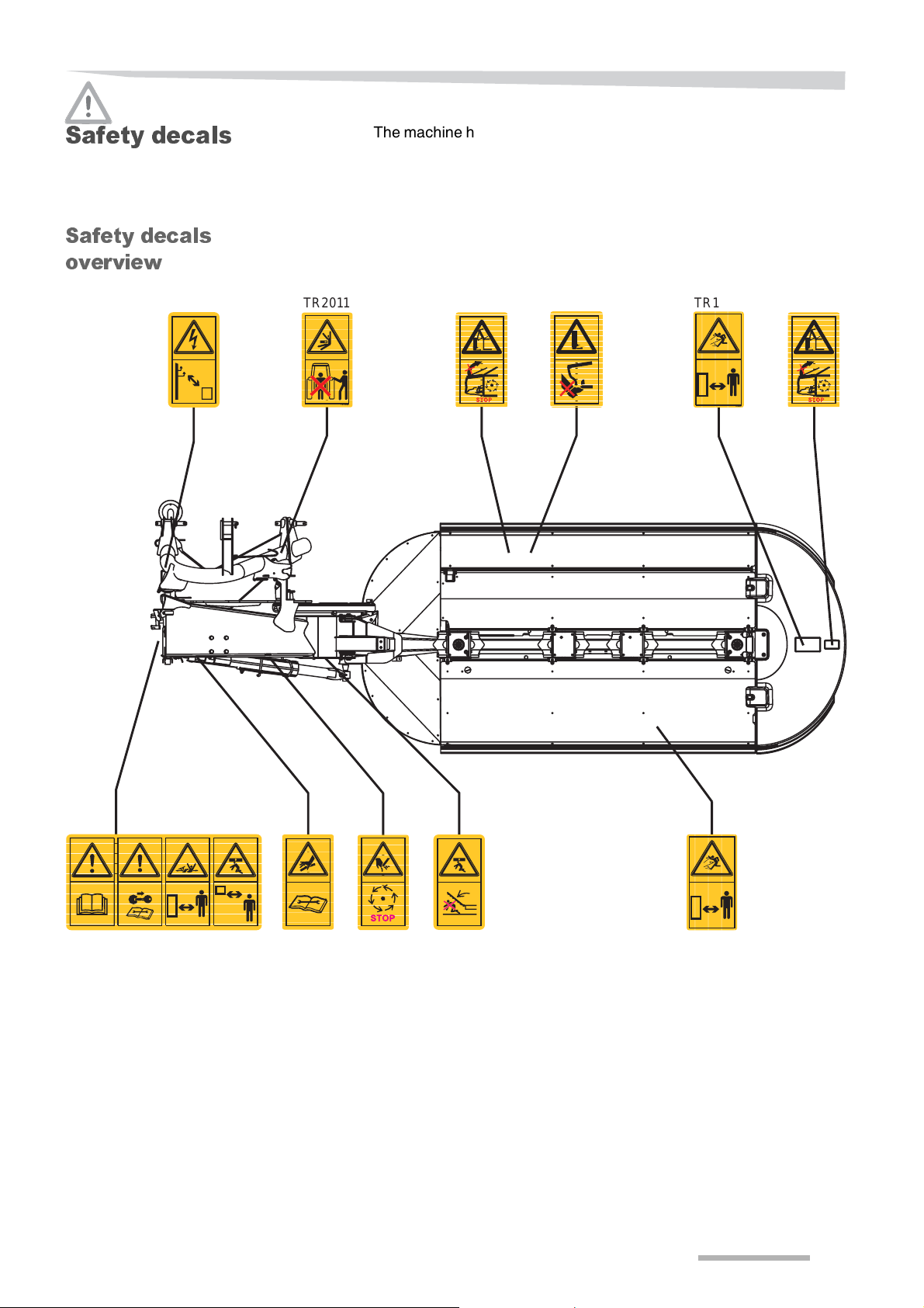
Safety decals
Safety decals
overview
TR2025
TR 2025
TR2011
The machine has safety decals for indicating attention to dangers. The
labels may not be removed. Keep all safety decals clean and legible.
In case safety decals are damaged, perished or lost, order new decals
as spare parts and affix them on the machine.
TR2095TR2097 TR2097
TR 2011
TR2097 TR2097
TR2095
TR1009
TR1009
TR3183
TR 3183
TR2055
TR2023
TR 2023
TR2007
TR 2007
TR1009
TR1009
TR 2055
9
Page 10

Safety instructions
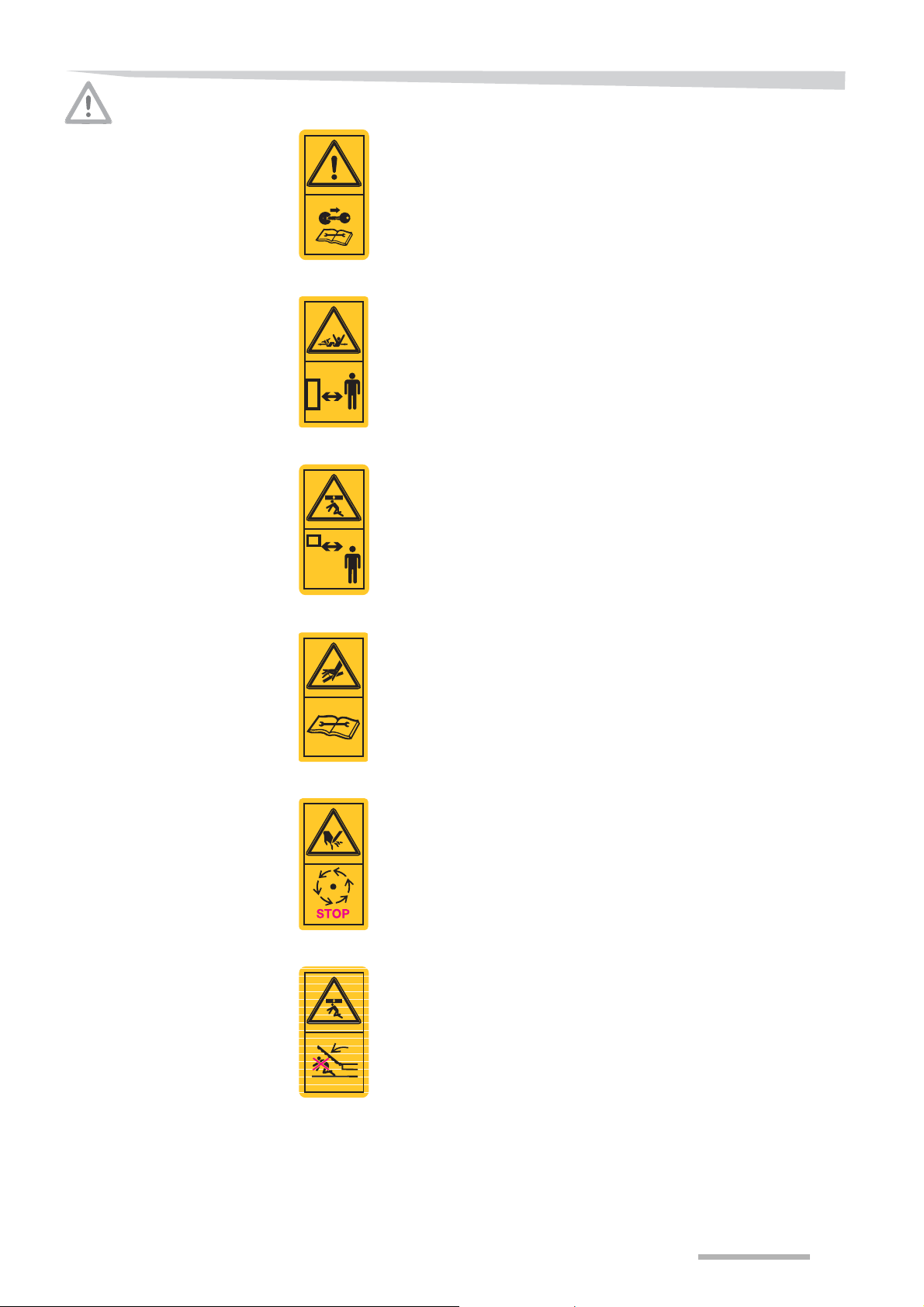
Meaning of the safety
decals
Keep sufficient distance from electrical power lines
Keep sufficient distance from electrical powerlines, especially when
driving with the machine in transport position.
TR 2025
Do not stand between the tractor and machine
During attachment/detachment of the machine, it is not allowed to stay
between the machine and the tractor. Danger of crushing.
TR 2011
Close shields and guards prior to operate the machine
Keep al shields and covers closed while the machine is running.
Do not open or remove any shield or guard untill the machine has come
to a complete standstill. Danger of serious injuries
TR2097
Never bring your feet under the machine
Never bring your feet under the machine while parts are running.
Feet can be cut off. Danger of serious injuries.
TR2095
Stay clear of a running machine
Keep at a safe distance of the machine; objects like stones and other
debris, may fly away at very high speed (250 - 300 km/h).
Danger of serious injuries
TR1009
Read the operation manual
The machine may only be commissioned once the operation manual
has been read and fully understood. This applies in particular to the
safety instructions.
10
TR 2085
Page 11
Safety instructions
Switch off the tractor engine
Carry out all maintenance, repair and adjusting jobs only when the
machine is at a complete standstill. Switch off electric systems,
hydraulic systems and the engine and remove the ignition key.
Otherwise serious or fatal injuries can occur.
TR 2005
Stay clear of a rotating drive line
Stay clear of the drive line, you may get grabbed by rotating machine
parts. Danger of serious or fatal injuries.
TR 2029
Stay clear of a raised machine
Keep distance from a raised machine, you may get hit when the
machine will be lowered. Danger of serious or fatal injuries.
TR 2015
Do not search for hydraulic leaks by hand
Never search for leaks by touching hydraulic hoses and hydraulic
connections, even when your hands are protected with a protective
skin cream or oil-resistant gloves.
Due to high pressure and very little holes in case of leakages, the
hydraulic oil will go through protection devices and your skin!
Hydraulic oil may come into your bloodstream, which is
TR 2055
lifethreatening!
Mass inertia of the machine
Due to mass inertia of the machine, the machine keeps running for a
while after switching off the PTO.
Stay clear of the machine until the machine has come to a complete
standstill. Danger of serious injuries.
TR 2023
Stay clear of the swinging area of the machine
Stay clear of the swinging area of the machine. Danger of crushing.
TR 2007
11
Page 12

Safety instructions
Who is al lo w e d to
operate the
machine?
General
Only qualified personnel
Only qualified personnel who have been informed about the dangers
associated with handling the machine are permitted to operate,
service or repair the machine. This knowledge can be gained by
agricultural training, technical training or intensive instruction.
Safety is your responsibility
Follow the safety regulations. Ensure you are always in compliance
with the safety regulations. Most accidents can be avoided by
observing the safety instructions.
Use a suitable tractor
Ensure that the tractor meets the listed minimum requirements of the
machine. Ensure that the tractor for safely operating the machine for
all your specific conditions.
→ »Tractor requirements«, see page 27.
Prescribed workwear
Do not wear loose, baggy clothing to avoid being caught by the
rotating parts. Wear workwear and protective clothing as prescribed
by the trade’s mutual indemnity association. Otherwise there is a high
risk of serious or fatal injury.
Oils, lubricants and chemicals
Observe all safety instructions and directions for use for oils,
lubricants and chemicals (like paint, cleaning agents, solvents etc.), as
mentioned on the original packaging or chemical cards.
Fire hazard
Ensure the machine is always clean and remove any remaining crop
to avoid fire hazards.
Fire extinguisher
Equip the machine with a multipurpose ABC fire extinguisher with a
capacity of at least 10 kg. Always use a fire extinguisher which is
approved by the relevant authorities.
Proper operating condition
Ensure that the machine and your tractor are always in a proper
operating condition. Always work with a clean machine, remove any
dirt before operation. Observe the information and technical data in
the operation manual of your tractor.
Running in enclosed space
A machine connected and coupled to the tractor may never be used
in enclosed spaces. Combustion engine exhaust fumes are
dangerous, and may cause asphyxiation.
Never work on a running machine
Never work on the machine while it is running. Objects or personnel
can be caught, drawn in or crushed. Fatal injuries can occur.
12
Page 13

Safety instructions
Do not modify the machine
No modifications whatsoever may be made to the machine.
Unauthorized modifications can impair safety and effect the life time of
the machine. It even renders the manufacturer’s guarantee null and
void and frees the manufacturer from all liability.
Fire hazards when welding
When welding, be careful of any fire or combustion hazards caused by
sprayed metal and sparks. Work away from flammable objects or cover
them. Seal off any gaps or chinks. Ensure there is a suitable fire
extinguisher device and check the working premises; check them again
at the end of the welding process.
13
Page 14

Safety instructions
Hitching the
machine
PTO drive shaft
Increased risk of injury
While hitching the machine to the tractor there is an increased danger
of injury. Therefore always:
• Secure the tractor and the machine from rolling and sliding away.
• Switch off all hydraulic systems.
• Switch off all electronic systems.
• Switch off the engine.
• Remove the ignition key.
• Never stay between the tractor and the machine during hitching.
Failure to comply may cause damage to the machine and even life
threatening injuries.
PTO drive shaft
Only use the PTO drive shaft complying with the manufacturer’s
specification. Other PTO drive shafts with overload clutches can
permit higher torques, which can damage the machine.
PTO drive shaft operation manual
Regard to the manufacturer’s operation manual of the PTO drive shaft
for correct use. Obey all instructions, particularly the safety and
maintenance instructions mentioned in the PTO drive shaft manual.
Negligence can lead to damages at the PTO drive shaft and to the
machine.
Fix and check PTO drive shaft protection
The rotating PTO drive shaft is secured by a PTO drive shaft
protection. Take care that the PTO drive shaft protection is not
damaged. Fix the PTO drive shaft protection both to the tractor and the
machine, to prevent the protection cover from rotating. Unprotected
PTO drive shafts can cause serious personal injuries.
PTO speed 540 rpm
The prescribed PTO speed of maximum 540 rpm may not be
exceeded. Higher PTO speeds can damage the machine.
Do not compress the PTO drive shaft
During operation or transport the PTO drive shaft may not be
compressed. Compressed PTO drive shafts can cause damages to the
tractor and machine.
14
Page 15
Safety instructions
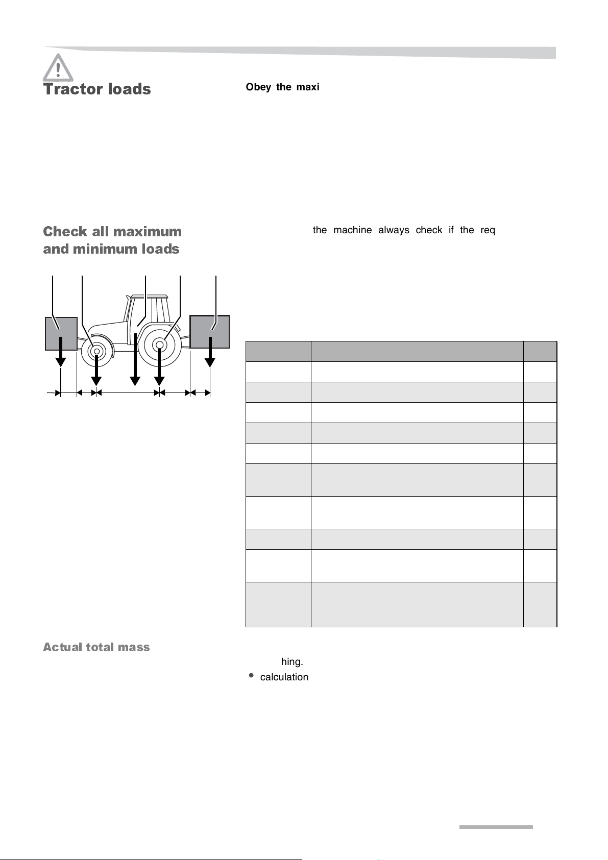
Tractor loads
Check all m a xi m um
and mini m um l oad s
B CA
D E
*
*
*
*
Obey the maximum permissible mass, permissible axle loads
and permissible tyre loads.
Attaching machines to the front or to the rear 3-point linkage may
never result in:
• Exceeding the maximum permissible mass.
• Exceeding the maximum permissible axle load.
• Exceeding the maximum permissible tractor tyre load.
• Not complying with the minimum front axle load.
• Not complying with the minimum rear axle load.
Before using the machine always check if the requirements as
mentioned above are met.
Most of the dimensions and masses in the figure at the left can be
found in the tractor manual or in the corresponding machine manual.
In case this data can not be found, contact the corresponding dealer
or measure or calculate this value.
Legend:
*
Dimension Description Unit
A Unladen tractor mass kg
F G
Actual total mass
IH J
B Unladen front axle load kg
C Unladen rear axle load kg
D Total mass front attachment kg
E Total mass rear attachment kg
F Distance from the lower link ball point centre
to the front attachment’s centre of gravity
G Distance from the front axle centre to the
lower link ball point centre
H Tractor wheel base mm
I Distance from the rear axle centre to the
lower link ball point centre
J Distance from the lower link ball point centre
to the rear attachment’s centre of gravity
→ »Technical specifications«, see page 26
The actual total mass can be determined by:
• weighing.
• calculation:
This value may never exceed the maximum permissible mass.
mm
mm
mm
mm
A + D + E = ........... kg
15
Page 16

Safety instructions
Actual front axle load
The actual front axle load can be determined by:
• weighing.
• calculation:
D x (F + G + H)
B +
H
The actual front axle load may never exceed the maximum
permissible front axle load.
The actual front axle load may never be less than the minimum front
axle load (M). In case the minimum front axle load (M) is not
mentioned in the tractor manual, the minimum front axle load (M) has
to be at least 20% of the unladen tractor mass (A).
In case the minimum front axle load is not met, you have to add front
ballast.
To calculate the minimum required front ballast:
E x (I + J) - (B x H) + (M x H)
F + G + H
N
OTE
In case front ballast is mounted directly at the tractor, replace “F + G”
in the formula by the “Distance from the centre point of the front axle
to the gravity point of the ballast”.
D x (F + G +H)
H
= .......... kg
= .......... kg
Actual rear axle load
Always check the maximum permissible mass, permissible axle load
and permissible tractor tyre load after mounting front ballast.
The actual rear axle load can be determined by:
• weighing.
• calculation:
E x (H + I + J)
C +
H
The actual rear axle load may never exceed the maximum permissible
rear axle load.
The actual rear axle load may never be less than the minimum rear
axle load (N). In case the minimum rear axle load (N) is not mentioned
in the tractor manual, the minimum rear axle load (N) has to be at least
45% of the unladen tractor mass (A).
In case the minimum rear axle load is not met, you have to add rear
ballast.
To calculate the minimum required rear ballast:
D x (F + G) - (C x H) + (N x H)
H + I + J
D x (F + G)
H
= .......... kg
= .......... kg
16
N
OTE
In case the front ballast is mounted directly at the tractor, replace “F +
G” in the formula by the “Distance from the centre point of the front
axle to the gravity point of the front ballast”.
Always check the maximum permissible mass, permissible axle load
and permissible tractor tyre load after mounting rear ballast.
Page 17

Safety instructions
Actual tyre load
The actual tyre load can be found by dividing the corresponding actual
axle load by 2.
The actual tyre load may never exceed the maximum permissible tyre
load.
N
OTE
The maximum permissible tyre load is depending on the tyre pressure
and the driving speed.
17
Page 18

Safety instructions
Hydraulics
Hydraulic couplings only pressureless
Only connect hydraulic hoses to the tractor hydraulic system if the
tractor and machine’s hydraulic system is pressureless. A pressurized
hydraulic system can trigger unforeseen movements at the machine
and may cause serious damage or fatal injury.
High pressure in the hydraulic system
The hydraulic system is under high pressure. All pipes, hoses,
couplings and connecting passageways have to be checked for leaks
and other damage on a regular basis. Only use suitable tools when
checking for leaks. Repair any damage immediately. Escaping oil can
cause injuries and burns. Seek medical care immediately when
injuries occur.
→ »Maintenance«, see page 51.
Searching for hydraulic oil leaks
Never search for leaks by touching hydraulic hoses and hydraulic
connections, even when your hands are protected with a protective
skin cream or oil-resistant gloves.
Due to high pressure and very little holes in case of leakages, the
hydraulic oil will go through protection devices and your skin!
Hydraulic oil may come into your bloodstream, which is
lifethreatening!
18
Page 19

Safety instructions
Road transport
Ensure road safety
If you intend to transport the machine on public roads, the machine
and the combination of tractor and machine have to comply to current
Road Traffic Act’s requirements. This to guarantee your own safety
and the safety of other road users.
For example ensure:
• The license plate, road lighting, warning and protective equipment
is properly installed, clean and functioning.
• Compliance with the permissible transport dimensions and weights
and axle loads.
• Compliance with the brake requirements of the tractor-machine
combination.
Failure to meet the Road Traffic Act’s requirements can result in fatal
accidents.
Block all hydraulic valves
To avoid inadvertently activation of machine components, activate all
machanical and/or hydraulic valve locks at the machine. Also lock the
hydraulic valves at the tractor, or disconnect the hydraulic hoses.
Carrying people and objects on the machine is prohibited
Neither persons nor objects are allowed to be transported at the
machine at any time. Only parts stored in their dedicated storage
locations are alllowed to be transported at the machine. Riding on the
machine is hazardous and strictly prohibited.
Altered driving and braking performance
Driving and braking performances will change when the machine is
attached to the tractor. Take the width and balance weight of the
machine into account, especially when cornering. A driving style that
is not adapted to altered conditions can cause accidents.
Adapted speed
In the event of bad road conditions and excessive speed, very high
forces can occur that subject can overload the tractor and machine.
Adapt the driving speed according to the road circumstances to avoid
accidents with serious or fatal injuries.
19
Page 20

Safety instructions
Operation
First use only after instruction
It is not allowed to operate the machine until distribution company
employees, company representatives or manufacturer’s employees
have given instruction. If initial operation is performed without
instruction, damage to the machine can be caused by operating errors
and accidents can occur.
Ensure that the machine is in perfect technical condition
Do not operate the machine unless it is in perfect condition. Check all
important components and (let) replace any defective component
before start operating. Defective parts can cause damage to materials
and injuries to persons.
Do not remove protective equipment
The protective equipment should not be removed or by-passed.
Check all protective equipment before operation. Unprotected
machine parts can cause serious or fatal injuries.
Carrying people and objects on the machine is prohibited
Neither persons nor objects are allowed to be transported at the
machine at any time. Only parts stored in their dedicated storage
locations are alllowed to be transported at the machine. Riding on the
machine is hazardous and strictly prohibited.
Make sure the direct surrounding is clear
Check the surrounding of the machine before starting and continually
during operation. Make sure that the operator has an adequate view
of the work area. Only start working if the direct surrounding is cleared
from any persons and objects to avoid serious or fatal injuries.
Tighten all bolts and nuts
Tighten all bolts and nuts regularly. Bolts and nuts may come loose by
using the machine. Loose or missing bolts and nuts can cause
damages to the machine or accidents.
Instructions in case of malfunctions
In case of a malfunction, stop the machine immediately:
• Switch off tractor hydraulics.
• Switch off electrical systems.
• Turn off tractor engine and.
• Remove the ignition key.
Perhaps the malfunction can be eliminated immediately, otherwise
contact your dealer. Using a faulty machine can cause accidents or
damage.
Observe the field conditions
Proceed with the utmost caution on hilly terrain or shifting subsoil.
Keep to both the maximum permissible engine load and the gross
working weight limit. A driving style which is not adapted to conditions
can cause accidents with serious or fatal injuries.
20
Page 21

Safety instructions
Cornering and turning manoeuvres
Centrifugal forces will occur during cornering. The machine’s centre of
gravity at the rear end of the tractor will be displaced. Be aware of the
turning radius and the moment of inertia.
PTO rotates after disengaging
After disengaging or switching off the PTO, the machine will continue
running because of inertia. Keep a safe distance to the machine until
all moving and rotating parts are at a complete stand still.
Blockage of a security device
In case of a blockage of a security device, never work on the machine
without
• Disengaging the PTO first.
• Switching off the tractor hydraulics.
• Switching off electronic systems.
• Switching off the tractor engine.
• Removing the ignition key.
Never try to repair a blockage or malfunction on a running machine.
Serious or fatal injuries can occur.
21
Page 22

Safety instructions
Unhitching the
machine
Increased risk of injury
An increased risk of injuries occurs when unhitching the machine from
the tractor. Therefore:
• Prevent the tractor and machine from rolling away.
• Switch off tractor hydraulics.
• Switch off electronic systems.
• Turn off tractor engine and remove the ignition key.
• Never stay between tractor and machine during unhitching.
• Take care of a level and secure surface for the machine.
• Take care of a secured support jack.
• Place the PTO drive shaft at the support or place it in the chain.
• Only detach the hydraulic hoses when the hydraulic system at the
tractor and the machine are pressureless.
In case of negligence heavy or deadly injuries can be the
consequence.
22
Page 23

Safety instructions
Maintenance
Observe the care and maintenance instructions
Observe the prescribed intervals for maintenance, checks and
inspections specified in this manual. If maintenance, checks and
inspections are not complied with, damage to the machine or
accidents can occur.
→ »Maintenance«,see page 51.
Use genuine parts
Only genuine parts are specially designed and thoroughly tested for
the use at this machine. Only genuine parts will guarantee the
reliability and safety of the machine. Other products can interrupt
functioning of the machine or make the machine unsafe. When using
non-genuine parts the warranty and liability of the manufacturer
reduces to nil and void.
Prevent the machine from inadvertent operating
Before carrying out maintenance and repair jobs always:
• Unhitch the machine from the tractor if possible and prevent it from
sliding away.
Otherwise always:
• Switch off the PTO.
• Switch off the tractor hydraulics.
• Switch off the electronic systems.
• Switch off the tractor engine.
• Remove the ignition key.
• Make sure the tractor and machine are positioned on a firm and
level area, support and prevent them from rolling or sliding away.
In case of negligence material damages and serious injuries can
occur.
Switch off electrical supply
Prior to carry out jobs at electrical equipment, disconnect it from the
power supply. Equipment under electrical power can cause damage
to equipment and injury to persons.
Climbing aids
Use suitable climbing aids only, never use components of the machine
as a climbing aid.
Replace hydraulic hoses every six years
Hydraulic hoses can age without any visible indications, therefore
replace all hydraulic hoses every six years. Defective hydraulic hoses
can cause serious or fatal injuries.
Searching for hydraulic oil leaks
Never search for leaks by touching hydraulic hoses and hydraulic
connections, even when your hands are protected with a protective
skin cream or oil-resistant gloves.
Due to high pressure and very little holes in case of leakages, the
hydraulic oil will go through protection devices and your skin!
Hydraulic oil may come into your bloodstream, which is
lifethreatening!
23
Page 24

Safety instructions
Caution when cleaning with a high-pressure cleaner
Avoid damage to the machine; bearings, seals and pipe unions may
not be contacted by the high pressure water jets.
No corrosive washing additives
Do not use any corrosive washing additives for cleaning. Bright metal
surfaces can be damaged.
Prior to carry out welding jobs
Unhitch the machine from the tractor if possible and prevent it from
rolling way before start welding. Otherwise always:
• Switch off the tractor hydraulics.
• Switch off electrical control system.
• Turn off tractor engine and remove ignition key.
• Disconnect all electrical and hydraulic connections from the tractor
to ensure the safety when carrying out welding jobs at the attached
machine.
In case of negligence material damages and serious injuries can occur.
Tighten bolted connections
Tighten all bolts and nuts that had to be unscrewed for maintenance
and repair jobs. Loose bolts and nuts can cause material damages
and serious personal injuries.
→ »Torques for bolted connections«, see page 56.
Further
prescriptions
Warranty and
responsibility
Observe the prescriptions
In addition to the safety instructions above, please also observe the
following:
• Accident prevention regulations.
• Generally recognized safety regulations, occupational health
requirements and road traffic regulations.
• Instructions given in this manual.
• Regulations pertaining to operation, maintenance and repair.
The warranty and manufacturer’s responsibility will no longer be valid
if:
• The safety instructions given in this manual are not obeyed.
• Maintenance and repair is carried out inadequate, incorrect, or not
carried out at all.
• Unqualified or untrained people carrye out maintenance anr repair.
• If the machine is overloaded.
• If the machine is used for other purposes for which it is intended.
• Unauthorized modifications are made to the machine.
24
Page 25

Familiarize yourself with the machine
Familiarize yourself w ith the machine
General
Product
description
Improper use of the
machine
Main components
overview
1
This chapter contains the following information:
• Range of applications and properties.
• Technical specifications.
This machine is designed for cutting of (non-)ligneous plants, mainly
grasses. Rotating knives cut the crop. By the drums a swath will be
created.
This machine is only designed for the use of agricultural purposes.
Any use whatsoever other than the above mentioned is improper use.
Neither the manufacturer nor the dealer is liable for any damage
resulting from improper use of the machine. In some cases, for
mowing unusual non-grassy plants a written authorization of the
manufacturer is required.
2
3 4 5
76
1Hitch frame
2 Hydraulic fold cylinder
3 Front guard
4 Mowing unit
5 Lateral Guard
6 Support jack
7 Hydraulic lift cylinder
25
Page 26

Familiarize yourself with the machine
Technical
specifications
Dimensions / Mass
Mass (kg) 800
L Lenght (mm) 1675
MW Mowing Width (mm) 3100
TW1 Transport Width 1 (mm) 1130
TW2 Transport Width 2 (mm) 1240
TH Transport Height (mm) 3220
J Distance lower tractor links to gravity point (mm) 850
PZ320
TH
TW1
J
TW2
MW
*
L
26
Page 27

Familiarize yourself with the machine
Machine
specifications
Number of mowing drums 4
Number of blades 12
Number of skid saucers 4
Cutting height adjustment 30 mm (continuously)
Cutting slope between -30° and +30°
Tractor requirem e nts
Minimum PTO power (kW / hp) 51 / 70
PTO speed (rpm) 540
PZ320
PZ320
Hitching category II
Minimum hydraulic oil pressure (bar) 180
Hydraulic connections 1 single acting control valve
Lighting power supply* 12V (DC) connector, 7 pin socket (DIN ISO 1724)
Optional equipment
Road lighting set
1 double acting control valve with pressureless return
* = Only necessary when road lighting [+] is installed.
27
Page 28

Delivery and preparation
Delivery and preparation
Check the scope
of delivery
The machine will arrive fully assembled. Check the machine after
delivery for loose or missing parts. In case parts are not assembled
please contact your dealer.
N
OTE
In case parts are missing or the machine got damaged during
transport, please submit a complaint immediately at your dealer,
importer, or the manufacturer.
.
Check list for parts Quantity
Operating manual 1
Spare part manual 1
Special accessories see delivery note
28
Page 29

Hitching the machine
Hitching the machine
Safety
Hydraulic
connections
Wear safety shoes
During all work at the machine never bring your feet under the
machine and always wear safety shoes. Wearing safety shoes
prevents and decreases the risk of serious injuries.
Before hitching the machine always:
• Prevent the tractor and machine from rolling away.
• Switch off all hydraulic systems.
• Switch off the tractor engine.
• Remove the ignition key.
• Never stand between the tractor and the machine during hitching.
In case of negligence serious or deadly injuries can occur.
Ensure the tractor is safe to use
Make sure that the tractor:
• Is in safe and good operating condition.
• Has adequate braking capabilities for the machine.
• Is able to carry and transport the machine.
A tractor which is not in a proper working condition can cause serious
personal and material damages.
Hydraulic connections only pressureless
Only connect hydraulic hoses to the tractor when all hydraulic systems
are pressureless. Hydraulics under pressure can cause accidental
movements of the machine with serious damage and injuries as a result.
Avoid oil mixture
If the machine is used at different tractors improper oil mixtures can
occur, which may destroy tractor and machine parts.
Avoid entering of dirt into the hydraulic system
The hydraulic system can get seriously damaged by dirt. Personal
injuries or material damage can be caused.
Check hoses and connections
Before connecting, check all hydraulic hoses for damages. After
connecting, check all hydraulic hoses for tight connection. Defective
hydraulic hoses or incorrect positioned hydraulic connectors can
cause unforeseen movements of the machine. Serious damage or
fatal injuries can occur.
Secure hydraulic devices
In transport position, secure the hydraulic control devices at the tractor
against unintended actuation and lock if possible. Unintended
actuation of the hydraulic device may lead to unexpected movements
of the machine. Fatal injuries and serious damage can be caused.
Check correct position and layout of hydraulic hoses
Hydraulic hoses may not be jammed or under tension. Pay attention
to sufficient play. Twisted or jammed hydraulic hoses can cause serious
injuries and damages to the machine.
29
Page 30

Hitching the machine
Hitching to the
3-point hitch
Lower link s
1
A
2
The machine is suitable for a catagory II 3-point hitch.
The lower link pins can be set according to:
• The track width of the tractor.
• An optional front mower
Before attaching the machine to the tractor, set the lower links pins in
the required position.
Setting Hitch catagory II
1 A = 1,04 m
2 B = 1,24 m
B
2
1
To set the lower link pins:
> Place the machine at the support jack.
> Loosen the bolts (2).
> Remove the lower link pins (1).
> Install the lower link pins (1) in the required position.
> Apply sealant agent to the screw thread of the bolts (2).
> Tighten the bolts (2).
30
Page 31

Hitching the machine
Hitching
1
4
2
3
> Before hitching the machine, ensure that both tractor lower links
are set at the same heigth.
> Hitch the machine to the tractor lower links and top link.
> Fix the tractor lower links to prevent the machine from moving
sideways. Use stabilisers or chains.
• Connect the blue marked hydraulic hoses (1) and (2), to the double
acting control valve.
• Connect the non-marked hydraulic hose (3) to the single acting
control valve.
> Use the lever (4) in the tractor to place the valve connected to the
blue marked hoses in floating position.
5 6
> Use the 3 point hitch to lift the machine fully.
> Remove the spring clip (6).
> Rectract the support jack (5).
31
Page 32

Hitching the machine
6
798
7
5
9
> Secure the support jack (5) with the spring clip (6).
> Remove the locking pin (9).
> Lift the locking device (7).
> Place back the locking pin (9) in the upper hole and secure the
locking pin.
10
32
11
10
11
> Use the 3-point hitch to place the hitch frame at the correct height.
The correct height is reached when the plate (11) points to the
indicator (10).
Page 33

Hitching the machine
Coupling the pto
drive s h af t
Pto drive shaf t
1
2
Do not use a hammer
It is not allowed to use a hammer or equivalent tools to mount the PTO
drive shaft. By using a hammer the PTO drive shaft can get seriously
damaged, which may lead to machine and tractor damages.
> Check the length of PTO drive shaft, before coupling.
> Shorten the PTO drive shaft if necessary, as described in the next
paragraphs.
> Ensure the tractor PTO is clean and greased.
> Connect the PTO drive shaft at both tractor and machine side.
> Ensure the shaft sliding ring catch with the slot of the PTO.
Fit the chains to rigid positions at both tractor and machine to prevent
the protection covers from rotating.
In some cases the length of the PTO drive shaft has to be adapted.
This is depending on the distance between tractor and machine
2
1 Protection tube
2 Profiled tube
1
Check length of the
PTO drive shaft
min. 37 cmmin. 5 cm
min. 5 cmA
Shortening the pto
drive shaft
Correct length
Never use a PTO drive shaft which is too long, this seriously damage
drive bearings of both tractor and machine.
Prior to coupling the PTO drive shaft check the length:
> Correctly line-up tractor and machine.
> Ensure the tractor PTO is clean and lubricated.
> Fit both PTO drive shaft halves (not connected!).
> Hold both PTO drive shaft halves together, ensure that:
• The protection tube shall be at least 5 cm shorter.
The overlap of the profiled drive tubes shall be at least 37 cm.
Make sure the PTO drive shaft is not damaged.
> Exactly determine the correct length of the shaft.
> Shorten the protection tubes.
> Shorten the profiled drive tubes.
The length of both cut-off ends has to be identical.
Clean cut ends of both protection and profile tubes to ensure they are
all smooth and clean.
A = B
33
Page 34

Hitching the machine
Electronic
connections[+]
Road lighting [+]
Check the cable layout
Take care of enough free space to avoid cables from getting stretched
twisted or torn. Stretched, twisted or torn cables may lead to machine
and tractor damages.
Check the cables and connections
Before connecting check all electronic cables for damages. After
connection check the electronic cables for tight connections.
Damaged or incorrect connected plugs may lead to machine and
tractor damages.
Connect the 7-pin connector (DIN ISO 1724) to the road lighting
connector at the tractor.
34
Page 35

Preparation for use
Preparation for use
Safety
Obey safety instructions
Obey the safety instructions at the execution of all work. Any disregard
for safety instructions can lead to serious or fatal injuries.
→ »Safety instructions«, see page 8.
Wear safety shoes
During all jobs at the machine never bring your feet under the machine
and always wear safety shoes, to decrease the risk of serious injuries.
Switch off the tractor and secure it
Never work at a running machine, make sure that:
> All hydraulic systems are switched off.
> The engine is switched off.
> The ignition key is removed.
> The electronic systems are switched off.
> The tractor is secured from rolling away.
In case of negligence, serious or deadly injuries can occur.
Check all hydraulic connections
Before use, check if all hydraulic connections are fitted correctly to the
corresponding single acting valves at the tractor. Incorrect connected
hydraulic hoses can cause unpredictable movements of the machine,
which may result in serious or fatal injuries.
Hitch frame
adjustment
1
2
Top link
adjustment
1
> Use the 3-point hitch to place the hitch frame at the correct height.
The correct height is reached when the plate (2) points to the
indicator (1).
2
The mowing angle can be adjusted by setting the top link of the tractor.
> Adjust the top link of the tractor in such a way that the machine
always stays horizontal or slightly tilts forward.
> Check if the machine only can tilt forward.
> Adjust the cutting height.
→ »Cutting height adjustment«, see page 43.
N
OTE
To avoid recutting, the mowing unit may never be tilted backwards.
35
Page 36

Preparation for use
Checklist
> Run the tractor hydraulics at idle.
> Run the machine for 540 rpm for some minutes.
> Check the components for operating correctly.
> Check for unusual noises.
> Switch off the tractor hydraulics.
> Switch off the PTO.
> Switch off the tractor engine and remove the ignition key.
> Tighten all bolted connections.
→ »Torques for bolted connections«, see page 56.
During the running-in period, special maintenance has to be carried
out.
→ »Maintenance table«, see page 54.
36
Page 37

Road transport
Road transport
Safety
Before road transport will take place, please read the following safety
instructions. The compliance is mandatory and helps you to avoid
accidents.
Observe safety instructions
Observe the safety instructions for carrying out all kind of jobs. Any
disregard for safety instructions may lead to serious or fatal injuries.
→ »Safety instructions«, see page 8.
Switch off all electronic controls and the hydraulic circuit
Always switch off the electronic systems, and switch off all hydraulic
systems. Inadvertently operating will be prevented this way, otherwise
material damages and fatal injuries can occur.
Make sure the machine is clean before road transport
Before transportation by road, make sure that the machine is clear and
clean from heavy dirt, remaining crop and soil. Crop, dirt or soil that
drops on the road, can cause slippery road conditions. Ensure that all
lighting equipment is free from remaining crop and dirt. Clean the
machine to avoid to traffic accidents.
Block all hydraulic valves
To avoid inadvertently activation of machine components, activate all
mechanical and/or hydraulic valve locks at the machine. Also lock the
hydraulic valves at the tractor or disconnect the hydraulic hoses.
Install and close all protective equipment
All protective covers and doors have to be installed, closed and secured
during road transportation. Material damages and personal injuries can
be caused.
Carrying people and objects on the machine is prohibited
Neither persons nor objects are allowed to be transported at the
machine at any time. Only parts stored in their dedicated storage
locations are alllowed to be transported at the machine. Riding on the
machine is hazardous and strictly prohibited.
Do not compress the PTO drive shaft
During operation or transport the PTO drive shaft may not be
compressed. Compressed PTO drive shafts can cause damages to
the tractor and machine.
Be aware of the transport height
Be aware ot the transport height of the combination of tractor and
machine, especially when driving under high-voltage cables and low
underpasses. Serious personal damages and heavy machine
damages can occur.
37
Page 38

Road transport
General
conditions
Place the machine
into transport
position
1
You have to put the machine into the transport position before road
transport may take place.
Next steps are necessary:
• Remove crop residues and heavy dirt.
• Install, close and secure all protective covers, unless stated
otherwise.
• Place the mowing unit into transport position.
• Switch off the electronic systems.
• Switch off all hydraulic systems.
• Close all hydraulic valves.
Before road transport may take place, the mowing unit has to be
placed in the transport position.
> Fold up and lock the lateral guard (1).
2
4
3
> Pull the rope (2) to lift the locking device of the hydraulic lift cylinder
(3). Keep the locking device lifted.
> Use the lever (4) in the tractor to extend the hydraulic lift cylinder.
The machine will be tilted to halfway position.
38
Page 39

Road transport
4
2
3
> Release the rope (2) and lower the locking device of the hydraulic
lift cylinder (3).
> Use the lever (4) in the tractor to retract the hydraulic fold cylinder.
The machine will be placed in transport position.
> Use the 3-point hitch to place the machine at the required transport
height.
39
Page 40

Road transport
Checklist
Prior to transport the machine on public roads, check if all conditions
of this checklist are met:
• Cables and hoses are routed in such a way that they can not get
stuck, nog get tensioned or interfere with other tractor and/or
machine parts?
• The tractor hydraulics are switched off?
• All hydraulic valves are closed?
• The PTO is switched off.
• The lateral guard is folded up and locked.
• Remaining crop and dirt is removed?
40
Page 41

Preparation at the field
Preparation at the field
Safety
Change settings
Obey the safety instructions
Obey the safety instructions at the execution of all work. Any disregard
for safety instructions can lead to serious or deadly injuries.
→ »Safety instructions«, see page 8.
Wear safety shoes
During all jobs at the machine never bring your feet under the machine
and always wear safety shoes, to decrease the risk of serious injuries.
Switch off the tractor and secure it
Never work at a running machine, make sure that:
> All hydraulic systems are switched off.
> The engine is switched off.
> The ignition key is removed.
> The electronic systems are switched off.
> The tractor is secured from rolling away.
In case of negligence, serious or deadly injuries can occur.
Only adapt the machine settings in the operating mode, as described
in the sections:
• Set the machine into operating mode.
• Checklist prior to operation.
Set the machine
into operating
mode
Set the machine in the operating mode;
• Place the mowing unit in operating position.
• Set the cutting height.
• Set the ground pressure compensation.
41
Page 42

Preparation at the field
Mowing unit
Place the mowing
unit into operating
position
1
> Use the lever (4) in the tractor to extend the hydraulic fold cylinder.
The machine will be lowered to halfway position.
2
1
3
> Pull the rope (2) and lift the locking device of the hydraulic lift
cylinder (3). Keep the locking device lifted.
> Use the lever (1) in the tractor to place the hydraulic system of the
tractor in floating position.
42
Page 43

2
4
3
Preparation at the field
> Release the rope to lower the locking device of the hydraulic lift
cylinder (3).
> Unlock and fold down the lateral guard (4).
> Use the 3-point front hitch to place the machine at correct height.
→ »Hitch frame adjustment«, see page 35.
Cutting heig ht
adjustment
2
1
3
The cutting height can be set by adjusting both outer drums.
Always place the mowing unit horizontal, before adjusting the cutting
height.
> Loosen the lock nut (2) with use of the blade detachment tool (3).
> Turn the bolt (1) clockwise to increase the cutting height (or
counterclockwise to decrease the cutting height).
> Tighten the lock nut (2) with use of the blade detachment tool (3).
43
Page 44

Preparation at the field
A
B
Ground pressure
adjustment
Ground pressure check
21
A
3
The ground pressure compensation can be set by an hydraulic
cylinder.
Always check the ground pressure before working with the machine:
> Lift the machine from the ground and make sure that the machine
stays fully horizontal.
> The ground pressure should be between 70 - 120 kg at each side.
> Adjust the ground pressure if required.
The ground pressure compensation will be set by putting an
accumulator under hydraulic pressure:
> Make sure that the machine is set at the correct height.
→ »Hitch frame adjustment«, see page 35.
→ »Place the mowing unit into operating position«, see page 42.
> Place the lever (2) in position B to open the ball valve (1) in the
hydraulic hose.
> Place the double acting control valve (at the tractor), which is
connected to the blue marked hoses, in the floating position.
> Open the hydraulic valve which is connected to the hose with the
ball valve (1) to put the accumulator under hydraulic pressure.
> Place the lever (2) in position A to close the ball valve (1).
> Place the corresponding hydraulic valve in floating position.
> Move lever (2) slowly towards position B until the pressure is
between 70 and 85 bar.
> The hydraulic pressure, displayed at the manometer (3), should be
between 70 and 85 bar.
> Check the ground pressure.
44
Page 45

Operation
Operat ion
Safety
Obey the safety instructions
Obey the safety instructions at the execution of all work. Any disregard
for safety instructions can lead to serious or fatal injuries.
→ »Safety instructions«, see page 8.
Carrying people and oblects on the machine is prohibited
Neither persons nor objects are allowed to be transported at the
machine at any time. Only parts stored in their dedicated storage
locations are allowed to be transported at the machine. Riding on the
machine is hazardous and strictly prohibited.
Take care for a clear view at the machine
Always take care for a clear view at the machine and monitor the
machine during mowing. Only start mowing if the direct surrounding is
free from any persons and objects, to avoid serious or fatal injuries.
Note the contour of the terrain
Be carefull when working on a slope. Avoid slopes on which the
combination of tractor and machine could slip away or turn over. Fatal
injuries and material damages can occur.
Tractor PTO speed maximum 540 rpm
The tractor PTO speed may never exceed 540 rpm, adapt the tractor
PTO speed to the crop condition. A higher rpm can cause machine
damages.
Start p os i ti on
Place the machine in the start position, the start position is reached
when:
• The tractor engine is running idle.
• The machine is in the operation position
• The 3-point hitch is in operating position.
45
Page 46

Operation
Mowing
Start mowing
1
Headland driving
1
End of the job
> Switch on the PTO at a low tractor engine rpm, to avoid damages
to the machine driveline due to the mass inertia of machine parts.
> Use the manual throttle at the tractor to keep a constant PTO
speed of 540 rpm.
> Lower the machine by using the hydraulic lift cylinder (1) and be
sure that the mowing drums are rotating at full speed (PTO at max.
540 rpm) before entering the crop.
> Start driving with a recommended speed between 8 and 12 km/h.
> Use the hydraulic lift cylinder (1) to lift the machine fully.
> Take curves always with a low speed, especially when making tight
curves and during turning around.
> Switch off the tractor PTO.
> When the machine has come to a complete stand still, place the
machine into transport position.
→ »Place the machine into transport position«, see page 38.
46
Page 47

Cleaning
Cleaning
Cleaning
Maintenan ce a fter
cleaning
After every use of the machine, empty and clean the machine off all
accumulated crop and dirt.
Cleaning can be done with a high pressure cleaner. Avoid bearings,
seals, hydraulic parts and bolted joints from water permeation.
Clean also the space between the drum skirts and the skid saucers.
After cleaning with a high pressure cleaner:
> Grease all bearings according to the maintenance instructions.
> Use oil or grease to protect the bright metal parts on the hydraulic
cylinders against corrosion.
> Repaint any damages.
→ »Maintenance table«, see page 54.
47
Page 48

Parking and storage
Parking and storage
Safety
Unhitching the
machine
1
Obey the safety instructions
Obey the safety instructions at the execution of all work. Any disregard
for safety instructions can lead to serious or fatal injuries.
→ »Safety instructions«, see page 8.
The machine is no toy
Store the machine in an area away from human activity. Never allow
children to play on or around the parked machine. Serious injuries can
occur.
Store the machine in the “operating position“.
> Place the machine in the operating position.
→ »Place the mowing unit into operating position«, see page 42.
> Before unhitching the machine, secure the tractor from rolling
away.
> Switch off the tractor PTO.
> Use the lever (1) in the tractor to place the valve connected to the
blue marked hoses in floating position.
243
> Use the 3 point hitch to lift the machine fully.
> Remove the locking pin (4) from the upper hole.
48
Page 49

Parking and storage
243
6
5 6
> Release the rope (3) to lower the locking device (2).
> Place the locking pin (4) in the lower hole.
> Remove the spring clip (6).
5
> Lower the support jack (5).
> Place the back the spring clip (6).
> Use the 3-point hitch to place the machine at the ground.
> Switch off the tractor hydraulics.
> Switch off the tractor engine.
> Disconnect the tractor lower links and the top link.
> Remove the PTO drive shaft, and place the PTO drive shaft in its
chains.
> Disconnect the hydraulic hoses.
> Disconnect the road lighting cable [+].
> Hang the hydraulic hoses and the road lighting cable over the
machine to prevent it from damages.
Recommendation:
Store the machine in a location which is free from rodents, insects and
martens.
49
Page 50

Parking and storage
After the season
At the end of the season or when the machine will be stored for a
longer period, carry out next jobs:
• Thoroughtly clean the machine.
→ »Cleaning«, see page 47.
• Carry out the prescibed maintenance.
→ »Maintenance table«, see page 54.
• Repair or replace all damages parts.
• Repaint any paint damages.
• Cover all bright metal parts with an oil film. Only use approved
biodegradable oil, like rape oil.
> Prevent the machine from sliding away.
50
Page 51

Maintenance
Maintenance
Safety
Obey the safety instructions
Obey the safety instructions at the execution of all work. Any disregard
for safety instructions can lead to serious or fatal injuries.
»Safety instructions«, see page 8.
Searching for hydraulic oil leaks
Never search for leaks by touching hydraulic hoses and hydraulic
connections, even when your hands are protected with a protective
skin cream or oil-resistant gloves.
Due to high pressure and very little holes in case of leakages, the
hydraulic oil will go through protection devices and your skin! Hydraulic
oil may come into your bloodstream, which is lifethreatening!
Wear safety shoes
During all jobs at the machine never bring your feet under the machine
and always wear safety shoes, to decrease the risk of serious injuries.
Conditions for maintenance jobs
Only carry out maintenance jobs if you have the required expertise
and the suitable tools. The absence of technical knowledge or
unsuitable tools can cause accidents or damages.
Use genuine parts
Only genuine parts are specially designed and thoroughly tested for
the use at this machine. Only genuine parts will guarantee the reliability
and safety of the machine. Other products can interrupt functioning of
the machine or make the machine unsafe. When using non-genuine
parts the warranty and liability of the manufacturer reduces to nil and
void.
Prevent the machine from inadvertent operating
Before carry out maintance and repair jobs always:
• Unhitch the machine from the tractor if possible and prevent the
machine from sliding away.
• Disconnect the hydraulic hose.
→ »Unhitching the machine«, see page 48 .
Otherwise always:
• Switch off the PTO.
• Switch off the hydraulic system.
• Switch off the tractor engine and remove the ignition key.
• Be sure that the tractor and machine combination is positioned on
a firm and lever surface. Prevent the combination of rolling away.
In case of negligence material damages and serious injuries can occur.
51
Page 52

Maintenance
Prior to carry out welding jobs
Unhitch the machine from the tractor if possible and prevent it from
rolling and sliding away before start welding. Otherwise always:
• Switch off all hydraulic systems.
• Switch off the engine and remove the ignition key.
• Disconnect all electrical and hydraulic connections to ensure the
safety when carrying out welding jobs at the attached machine.
In case of negligence material damages and serious injuries can
occur.
Climbing aids
Use suitable climbing aids only, never use components of the machine
as a climbing aid.
Protection m eas ures
Additives in oil and lubricants may have harmful effects to health. Be
always aware of the safety instructions, warnings and cautions
mentioned at the original package of the oil and lubricants.
Because an indication according to the danger order is not necessary,
therefore pay attention to the instructions below.
Avoid skin contact
Avoid skin contact with oil and lubricants. Always use a protective skin
cream or oil-resistant gloves. In case skin deseases occur due to skin
contact with oil or lubricants, contact a doctor immediately.
Discard contaminated cleaning cloths
Discard all oil contaminated cleaning cloths immediately. Oils may
cause damages to your health.
Do not use oil for cleaning
Never use oil and lubricants for hand cleaning! Chips and waste in this
oil and lubricants can extra lead to injuries.
N
OTE
Collect wasted oil, lubricants and oil contaminated cloths, and dispose
them according to local and national environmental regulations.
52
Page 53

Maintenance
General
Directions
Direction Description
Left Counterclockwise
Right Clockwise
Rotation around a horizontal axis As seen at right angles to the direction of travel from left to right
Rotation around a vertical axis As seen from top to bottom
Maintenan ce term s
Task Explanation
Grease Apply grease to the sliding surface by using a brush
At all maintenance tasks, secure the machine in the operating
position. In case the transport position is required, this is mentioned
separately.
Direction specifications (left, right, front, rear) are always meant in
relation to direction of travel.
In the table below you will find some short explanations of the most
common maintenance tasks.
Lubricate One or two presses with a grease gun, unless stated otherwise.
Oil Apply an oil film (to the sliding face).
Replenish Fill up fluids, oil or lubricants to the indicated maximum level.
Replace Remove a part and install a new part. Drain fluids, oils or lubricants
and replenish to the indicated maximum level.
Check Check the condition of parts and components, and replace if
necessary. Check the levels of all fluids, oils and lubricants,
replenish to the indicated maximum level if necessary.
Lubricants
specifications
Lubricant Specifications
Oil Class NLGI2, K2k in accordance with DIN51825
Gearbox Oil SAE 85W-90 API GL-5
Grease Multipurpose, grade EP 2
53
Page 54

Maintenance
Maintenance table
After the first 5 operating hours
»Complete machine«
»Complete machine«
»Safety decals«
»Road lighting [+]«
»Road lighting [+]«
»Bolted connections«
»Bolts and nuts«
»Drums«
»Mowing blades«
»Mowing blade holders«
»Bevel gearbox«
»Oil level«
»Oil change«
»Inner gearboxes and outer gearboxes«
»Oil level«
»Oil change«
»Drive shafts«
»PTO drive shaft«
»Secondary drive shaft«
»Propulsion shaft«
»Overload clutch«
»Hitch frame«
»Hitch frame«
• • • • •
• • • •
Before carry out maintenance or repairs always:
• Clean the machine.
→ »Cleaning«, see page 47.
• Obey all safety instructions.
→ »Safety instructions«, see page 8.
→ »Safety«, see page 51.
• Obey all protection measures.
• »Protection measures«, see page 52.
Oil
Grease
Lubricate
road transport
After operation
Every 10 operating hours
Every 20 operating hours
Every 50 operating hours
Every 150 operating hours
After the first 10 operating hours
Before operation and/or
Every 250 operating hours
At the start of each season
At the end of each season /
before storage
Tighten
Check
Clean
Change / Replace
• • • •
••• •
• • •
• ••• •
••
• • •
••
• • •
••
• • • • • • •
••• • ••
• • • • • •
••
• • • •
Page
55
55
55
55
55
57
57
61
62
62
63
64
65
65
66
67
54
Page 55

Maintenance
Complete machine
Safety decals
Road lighting [+]
Clean the machine always:
• After operation.
• At the start of each season.
• At the end of each season.
• Before storage.
→ »Cleaning«, see page 47.
→ »Parking and storage«, see page 48.
Keep all safety decals clean and legible. In case safety decals are
damaged, perished or lost, order new decals as spare parts and affix
them on the machine.
→ »Safety decals overview«, see page 9.
Always clean the machine before checking the safety decals.
→ »Cleaning«, see page 47.
Check the safety decals:
• After operation.
• At the start of each season.
• At the end of each season.
Check road lighting for proper working:
• Before road transport.
• At the start of each season.
Repair defect road lighting immediately.
Bolted
connections
Bolts and nuts
Clean all lighting equipment:
• Before road transport.
• After operation.
• At the start of each season.
• At the end of each season.
Replace a missing or broken bolt or nut, always by a genuine part.
Standard bolts and nuts may look the same, but can have different
qualities and properties. Non-genuine parts may change the
properties of the machine, and may make the machine unsafe.
Material damages or serious injuries can occur.
Always use a suitable torque wrench to tighten bolts and nuts.
Always check for missing bolts and nuts, install new bolts and nuts if
necessary.
Tighten all bolts and nuts:
• After the first 5 operating hours.
• After the first 10 operating hours.
• Every 150 operating hours.
• At the start of each new season.
• After a bolt or nut has been unscrewed.
→ »Torques for bolted connections«, see page 56.
55
Page 56

Maintenance
Torques for bolted
connections
Thread Torque value Spanner
size*
8.8 10.9 12.9
Nm mm
M3 1.3 1.8 2.1 6
M4 2.9 4.1 1.9 7
M5 5.7 8.1 9.7 8
M6 9.9 14 17 10
M8 24 34 41 13
M10 48 68 81 17 (15)
M12 85 120 145 19 (17)
M14 135 190 225 22 (19)
M16 210 290 350 24 (22)
M18 290 400 480 27
M20 400 570 680 30
M22 550 770 920 32
M24 700 980 1180 36
M27 1040 1460 1750 41
M30 1410 1980 2350 46
M33 1910 2700 3200 50
M36 2450 2546 3063 55
M39 3200 4500 5400 60
* Values in brackets: spanner size for locking bolts and nuts with
toothed flange.
N
OTE
• The values listed apply to dry or slightly lubricated connections.
• Do not use galvanized (plated) bolts and nuts without grease.
• When using a stiff grease, reduce the value in the table with 10%.
• When using (self-)locking bolts and nuts increase the value in the
table with 10%.
56
Page 57

Drums
Maintenance
Mowing blades
Wear safety gloves
Mowing blades are very sharp. Always wear safety gloves when
handling mowing blades to prevent serious injuries.
Check the mowing blade cutting edges for sharpness:
• Before operating.
• After the first 5 operating hours.
• At the start of the season.
Replace or change the mowing blades if required. Always change or
replace all mowing blades per drum.
Ensure there are always 4 mowing blades mounted per outer drum
and 2 blades mounted per inner drum.
Each mowing blade has two cutting edges. As soon as one edge of
the mowing blades has been worn, mount the mowing blades upside
down.
An arrow at each mowing blade shows the direction of rotation.
> Place the machine in the operating position.
→ »Place the mowing unit into operating position«, see page 42.
> Place the blade detachment tool (2) between the drum skirt (1) and
21
the blade holder (3).
> Move the blade detachment tool (2) upwards to release the
mowing blade.
> Keep the blade detachment tool (2) upwards and replace the
mowing blade.
> Lower the blade detachment tool (2) to lock the mowing blade.
Mowing blade
holders
1
3
Check the condition of the mowing blade holders:
• At the start of the season.
• After change or replacement of mowing blades.
Replace the mowing blade holders if:
• Distance X is equal to 0 mm or the blade pin is worn off.
• The diameter Y of the blade pin (1) is less than 7 mm.
X
Y
Always replace the blade holders per drum.
Always use new bolts and nuts when replacing blade holders.
57
Page 58

Maintenance
Inner drums blade holder
replacement
BYXA
1 2
3
4
5
6
To replace the blade holders of the inner drums (A) and (B):
Use the 3-point hitch to lift the
>
> Rotate the drums manually into the basic position as shown in the
picture at the left.
> Unscrew the skid saucer bolts (1).
> Remove the skid saucer (2).
> Unscrew the blade holder bolts (8).
> Discard the blade holder bolts (8) and the spring washers (7).
> Remove the blade holders (6), the bushings (5), the wear plate (4)
and the covers (3).
> Install the covers (3), the wear plate (4), the bushings (5), the new
blade holders (6).
> Place new spring washers (7) and new blade holder bolts (8).
> Tighten the blade holder bolts (8) to 85 Nm.
> Place back the skid saucer (2).
> Apply locking agent to the screw thread of the skid saucer bolts (1).
> Place back the skid saucer bolts (1) and tighten the bolts (1) to 80
Nm.
machine fully and secure the machine.
58
7
8
Page 59

Maintenance
Outer drums blade holder
replacement
BYXA
321
4
5
6
7
To replace the blade holders of the outer drums (X) and (Y):
Use the 3-point hitch to lift
>
> Rotate the drums manually into basic position as shown in the
picture at the left.
> Unscrew the skid saucer bolts (1).
> Remove and discard the spring washers (2).
> Remove the skid saucer (3).
> Unscrew and discard the blade holder bolts (4) and nuts (7).
> Remove the wear plate (3) and the blade holders (6).
> Install the wear plate (3) and the new blade holders (6).
> Place new blade holder bolts (4) and nuts (7.
> Tighten the blade holder (7) to 135 Nm.
> Place back the skid saucer (3).
> Apply locking agent to the thread of the skid saucer bolts (1).
> Place back the skid saucer bolts (1) and new spring washers (2).
> Tighten the skid saucer bolts (1) to 80 Nm.
the machine fully and secure the machine.
59
Page 60

Maintenance
Gearboxes
1
The machine unit is equipped with 5 gearboxes; a bevel gearbox and
4 gear boxes in the main frame.
Each gearbox is filled with oil
→ »Lubricants specifications«, see page 53.
2
3 2
Contents
Gearbox Contents (dm3)
1 Bevel gearbox 1,50
2 Outer gearbox 0,70
3 Inner gearbox 0,50
60
Page 61

Maintenance
Oil level
Bevel gearbox
Before checking the oil level always:
• Place the machine in operating position.
→ »Place the mowing unit into operating position«, see page 42.
• Place the machine fully horizontal.
• Direct after operating or when the mowing unit is tilted horizontally
from the transport position, wait a few minutes for the oil is
uniformely distributed in the gearbox.
Otherwise an incorrect oil level can be indicated, which may lead
to serious machine damages.
Check the oil level of all gearboxes:
• After every 20 operating hours.
• At the start of each season.
• In case of loss of oil.
Never work with the machine in case the oil level in one or more
gearboxes is too low. This to prevent the machine from heavy material
damages.
> Slowly unscrew the check plug (4) at the side of the bevel gearbox
(1), until oil comes out.
51 4
If no oil comes out, replenish the bevel gearbox (1):
> Unscrew filler plug (5).
> Pour the oil through the filler plug opening.
→ »Contents« see page 60
> Place back and tighten the filler plug (5).
> Check the oil level again, as described above.
41
61
Page 62

Maintenance
Inner gearboxes and
outer gearboxes
3
6 2
6
max
The procedure to check the oil level is the same for all inner (3) and
outer (2) gearboxes:
> Unscrew and remove the dipstick (6), the oil level has to be
between the “min“ and “max” indication.
> Replenish the gearbox if the oil level is equal to, or below the “min“
indication. Pour the oil through the dipstick opening.
→ »Contents« see page 60.
> Place back and tigthen the dipstick (6).
In case oil is replenished:
> Repeat the procedure as described above until the oil level is
between the “min“ and “max” indication.
Oil chang e
Bevel gearbox
7 41
51 4
min
Always change the oil:
• At the start of each season.
• In case the corresponding gearbox was opened (for repair).
> Place an oil bin below the drain plug (7).
> Unscrew and remove the drain plug (7).
> Unscrew and remove the filler plug (5) to bleed the bevel gearbox
(1) more quickly.
> When the bevel gearbox (1) is empty, place back the drain plug (7)
and tighten.
> Remove the oil bin and dispose of the oil to the current valid
national waste disposal regulations.
> Fill up the bevel gearbox (1) with new oil. Pour the oil through the
filler plug opening.
→ »Contents« see page 60
> Place back and tighten the filler plug (5).
> Check the oil level.
→ »Oil level«, see page 61.
62
Page 63

Maintenance
Inner gearboxes and
outer gearboxes
8
6
The oil changing procedure is the same for all inner and outer
gearboxes.
To change the oil:
> Place an oil bin below the drain plug (8).
> Unscrew and remove the drain plug (8).
> Unscrew and remove the dipstick (6) to bleed the gearbox.
> When the gearbox is empty, place back the drain plug (8) and
tighten.
> Remove the oil bin and dispose of the oil to the current valid
national waste disposal regulations.
> Fill up the gearbox with new oil. Pour the oil through the dipstick
opening.
→ »Contents« see page 60.
> Place back and tigthen the dipstick (8).
> Check the oil level.
→ »Oil level« see page 62.
63
Page 64

Maintenance
Drive shafts
1 2
PTO drive shaft
3
54 4
3
Read the drive shaft manual.
Read and observe the manufacturer’s operation manual of the drive
shafts. Especially obey the safety and maintenance instructions.
Protective parts
All protective parts of the PTO drive shaft (1) have to be in a proper
and undamaged condition. Replace defective parts. An unprotected
drive shaft or damaged protective parts can cause serious injuries.
Check the PTO drive shaft (1) and protection covers for wear and
damages:
• After the first 10 operating hours.
• Every 50 operating hours.
• At the start of each season.
• After cleaning with a high pressure cleaner.
Disconnect the PTO drive shaft from the machine and the tractor.
Use a grease gun to press grease into the lubrication points (3).
Lubricate the PTO drive shaft:
• After the first 10 operating hours.
• Every 250 operating hours.
• At the start of each season.
• After cleaning with a high pressure cleaner.
Use a grease gun to press grease into the lubrication points (4).
Lubricate the PTO drive shaft:
• After the first 10 operating hours.
• Every 50 operating hours.
• At the start of each season.
• After cleaning with a high pressure cleaner.
Use a brush to grease the sliding tubes (5):
• After the first 10 operating hours.
• Every 50 operating hours.
• At the start of each season.
• After cleaning with a high pressure cleaner
64
Before connecting the PTO drive shaft to the machine and the tractor
always:
> Check the tubes of the PTO drive shaft for sliding correctly.
Page 65

Secondary dri ve
shaft
Maintenance
> Fold up the protection cover (6).
7
7
8
6
Check the secondary drive shaft (2) for wear and damages:
• After the first 10 operating hours.
• Every 50 operating hours.
• At the start of each season.
• After cleaning with a high pressure cleaner.
Press grease into the lubrication points (7).
Lubricate the secondary drive shaft:
• After the first 10 operating hours.
• Every 50 operating hours.
• At the start of each season.
• After cleaning with a high pressure cleaner.
Press grease into the lubrication points (8).
Lubricate the secondary drive shaft:
• After the first 10 operating hours.
• Every 250 operating hours.
• At the start of each season.
• After cleaning with a high pressure cleaner.
> Fold down the protection cover (6).
Propulsion shaft
10911
12
13
> Unscrew the bolts (10) at both sides of the protection cover (9).
> Remove the bolts (10) and washers (11).
> Remove the protective cover (9).
Check the propulsion shaft (13) for wear and damages:
• After the first 10 operating hours.
• Every 250 operating hours.
• At the start of each season.
• After cleaning with a high pressure cleaner.
Press grease into the lubrication point (12) at the propulsion shaft (13).
Lubricate the propulsion shaft:
• After the first 10 operating hours.
• Every 250 operating hours.
• At the start of each season.
• After cleaning with a high pressure cleaner.
> Place back the protective cover (9).
> Place back the washers (11) and the bolts (10).
> Tighten the bolts (10) at both sides of the protective cover (9).
65
Page 66

Maintenance
Overload cl utc h
1
14
15
The overload clutch (14) is located between the PTO drive shaft (1)
and the bevel gearbox (15).
Check the overload clutch (14) for correct functioning:
• At the start of each season.
To check the overload clutch (14):
> Tighten the six nuts (16) until the overload clutch (9) will rotate
freely from the bevel gearbox (15). In case the overload clutch (9)
will not rotate freely, replace the overload clutch (14).
> Loosen the six nuts (16) to the end of the thread, the nuts may not
come off.
16
66
Page 67

Maintenance
Hitch frame
Lubricate the hitch frame:
• After the first 10 operating hours.
• Every 10 operating hours.
• At the start of each season.
• After cleaning with a high pressure cleaner.
1
> Press grease into the lubrication points (1) till (8).
2
3
4
6
5
7
8
67
Page 68

Troubleshooting
Troubleshooting
General
Before start to resolve problems, always secure the machine and
tractor from rolling away and unintentional operating.
Always observe all safety instructions during maintenance and repair
jobs. See also chapter maintenance.
→ »Safety instructions«, see page 8.
→ »Safety«, see page 51.
→ »Protection measures«, see page 52.
In most cases problems, failures and defects can be solved very quick
and easily. Before contacting a dealer or the service department,
please check if you can solve the problem yourself, using the
information and instructions of this chapter as a guideline.
Always contact your dealer if:
• The problem, failure or defect cannot be found.
• The problem, failure or defect cannot be solved.
• The operator cannot repair the machine.
• This is mentioned in this operation manual.
Before restarting the tractor and machine in case of any problems,
defects or failures, always:
• Solve the problem first, in case the problem cannot be solved,
contact your dealer.
• If possibile, repair or replace defect parts first, otherwise contact
your dealer.
It is not allowed to use a defect machine.
Material damages and serious injuries can occur.
68
Page 69

Mowing unit
Problem Cause Solution Page
Troubleshooting
Machine does not rotate
Bad ground adaptation • Mowing unit not in correct
• The overload clutch slips > Decrease the operating
operating position
• Ground pressure adaptation
not correct
Bad mowing results
• Rpm too low > Increase the rpm
• Left and right mowing blades
switched
• Mowing blades are blunt or
damaged
speed
> Remove the blockage
> Check if the clutch is
broken/worn. Repair or
replace if required
> Place the mowing unit into
operating position
> Adjust the ground pressure 44
> Switch the left and right
mowing blades
> Mount the mowing blades
upside down
> Replace the mowing
blades
42
57
57
• Ground pressure is too low > Increase the ground
Machine keeps mowing / mows
the swath while headland driving
Machine unable to lift (for
headland driving)
Machine does not lower to
operating position
• Hitch frame hight is too low > Place the hitch frame at
• Hydraulic lift cylinder is locked > Unlock the hydraulic lift
• Hydraulic lift cylinder is locked > Unlock the hydraulic lift
• Ground pressure is too high > Adjust the ground pressure 44
Hydraulics
Problem Cause Solution Page
Oil heats up
Hydraulic cylinder does not move • Hydraulic system is blocked or
• Hydraulic system is blocked or
contaminated
contaminated
44
pressure
the correct height.
cylinders
cylinders
> Contact your dealer
> Contact your dealer
• Hydraulic system is leaking > Check the hydraulic hoses
for leakage
> Check the hydraulic
cylinder for leakage
69
Page 70

Optional equipment
Optional equipment
General
Road lighting set
The optional equipment includes accessories (fitted afterwards) and
options (factory fitted).
When ordering spare parts and accessories, always mention the
machine identification numbers.
Only use genuine (spare) parts and original accessories, because
these parts are specially designed and thoroughly tested for the use
at this machine. The use of genuine parts and original accessories will
guarantee the reliability and safety of the machine. Other products can
interrupt functioning or make the machine unsafe. When using nongenuine parts and/or non-original accessories the warranty and
liability of the manufacturer reduces to nil and void.
Accessories may only be mounted at the machine:
• According to the assembly instructions.
• To the appropriate fixing points.
70
Page 71

Disposal of the machine
At the end of the machine’s lifetime, the individual components have
to be disposed of in a correct environmentally friendly way.
Please observe the current valid national waste disposal regulations.
Metal parts
All metal parts can be disposed of in the used metal recycling system.
Oil and oil bearing parts
All used hydraulic oils, lubricants and oil-bearing parts (like hydraulic
hoses) have to be stored, collected and disposed of separately
according to the current valid national waste disposal regulations.
Plastic parts
All plastic parts can be recycled. Dispose of all plastic parts according
to the current valid national waste disposal regulations.
Rubber parts
Rubber parts like hoses and tyres have to be recycled by a rubber
recycling company.
Disposal of the machine
71
Page 72

EC Declaration of conformity
In accordance with EU
Directive 2006/42/EC
We
KUHN-GELDROP B.V.
Nuenenseweg 165
5667 KP Geldrop
The Netherlands
declare under our sole responsibility that the product
EC Declaration of confor mity
Identification plate
PZ320 and accessories
to which this declaration relates, conforms to the relevant basic safety
and health requirements of EU Directive 2006/42/EC.
For the relevant implementation of the safety and health requirements
mentioned in the EU Directive, the following standards have been
taken into account:
• EN 12100-1;2
• EN 745
KUHN-GELDROP B.V.
Geldrop, 21.04.2010
72
Gita Hoogeveen
Managing Director
Page 73

Index
Index
B
Bolted connections
Maintenance
Torques for bolted connections 56
55
C
Cleaning 47
Complete machine
Maintenance
Coupling the PTO drive shaft
Cutting height adjustment
55
33
43
D
Delivery and preparation
Check the scope of delivery
Disposal of the machine
Drive shafts
Maintenance
64
71
28
E
EC Declaration of conformity 72
Electronic connections
Hitching the machine
Road lighting
34
34
F
Familiarize yourself with the machine
Main components overview
Technical specifications
Tractor requirements 27
25
26
G
Gearboxes
Maintenance
Ground pressure adjustment
60
44
H
Headland driving 46
Hitch frame
Adjustment
Maintenance 67
Hitching the machine
Coupling the PTO drive shaft
Electronic connections 34
Hitching to the 3 point hitch
Safety instructions
Hydraulics
Safety instructions
Troubleshooting
35
33
30
14, 29
18
69
L
Lubricants specifications 53
M
Main components overview 25
Maintenance 51
Bolted connections
Complete machine
Drive shafts 64
Gearboxes
General
Hitch framel 67
Lubricants specifications
Maintenance table
Mowing blade holders 57
Mowing blades
Overload clutch
Protection measures 52
Road lighting
Safety decals
Safety instructions 23, 51
Torques for bolted connections
Mowing
End of job
Headland driving
Start mowing
Mowing blade holder
Maintenance
Mowing blades
Maintenance
Mowing unit
Cutting height adjustment
Ground pressure adjustment 44
Place into operating position
Troubleshooting
60
53
46
55
55
53
54
57
66
55
55
56
46
46
57
57
43
42
69
O
Operation
Mowing
End of job
Headland driving
Start mowing 46
Safety instructions
Start position
Overload clutch
Maintenance
46
46
20, 45
45
66
73
Page 74

Index
P
Parking and storage
After the season 50
Safety instructions
Unhitching the machine
Preface
Symbols used
Preparation at the field
Cutting height adjustment
Ground pressure adjustment
Moving into working position
Safety instructions 41
Preparation for use
Hitch frame adjustment
Safety instructions 35
Top link adjustment
Protection measures
PTO drive shaft
Coupling the PTO drive shaft
Safety instructions
48
48
7
43
44
42
35
35
52
33
14
R
Road lighting 34
Maintenance
Road transport
General conditions
Place the machine in transport position
Safety instructions
55
38
38
19, 37
T
Technical specifications 26
Top link adjustment 35
Torques for boltes connections
Tractor loads
Tractor requirements 27
Troubleshooting
Hydraulics
Mowing unit 69
15
69
56
U
Unhitching the machine 48
Safety instructions
22
S
Safety decals
Maintenance
Meaning of safety decals
overview 9
Safety instructions
Hitching the machine
Hydraulics 18
Maintenance
Operation
Parking and storage 48
Preparation at the field
Preparation for use
PTO drive shaft 14
Road transport
Safety decals
Tractor loads 15
Unhitching the machine
Symbols used
55
10
14, 29
23, 51
20, 45
41
35
19, 37
9, 10
22
7
74
 Loading...