

Page 1
1
INSTRUCTION MANUAL
PRIMOR STRAW BLOWER
A7310104 3 09-00
PLEASE READ CAREFULLY BEFORE USING THE MACHINE
Page 2

2
Manufacturer’s address: KUHN-AUDUREAU S.A., B.P . 19, F-85260 LA COPECHAGNIERE
IMPORTANT INFORMATION
The KUHN machine that you have just purchased has undergone a full range of inspections throughout
the manufacturing process. If you should encounter a fault in spite of all the care given to the manufacture of your machine, please contact your dealer who will solve the problem with the assistance of our
after-sales service.
To enable us to satisfy your requirements, please provide the information below when you call us. It
will only take you a few minutes to fill in this page when your machine is delivered but it will save you
a lot of time in the event of a problem.
1- GENERAL DA TA
Note the machine references here.
KUHN
PRIMOR
Type of machine Sequence number in the series Date commissioned
2 - OPTIONAL EQUIPMENT
Tick the boxes corresponding to the options fitted to your machine.
Electric control Wide angle PTO shaft
Rectangular bales kit Chute type of standard Primor on Primor PH
Sealed floor Category 2/3 linkage bar
Page 3

3
CONTENTS
Page
MESSAGE TO THE USER _________________________________ 4
SAFETY INSTRUCTIONS ___________________________________ 5 - 10
SAFETY LABELS _________________________________________ 12
LIGHTING EQUIPMENT _____________________________________ 14
DESCRIPTION OF THE PRIMOR STRAW BLOWER _____________ 16 - 17
TECHNICAL SPECIFICATIONS
Mounted PRIMOR _________________________________________ 18 - 19
Semi-Mounted PRIMOR _______________________________________ 20 - 21
Description of the Controls ____________________________________ 22 - 25
STARTING UP ___________________________________________ 26
Hitching ___________________________________________________ 27
Adjusting the Position of the Controls ____________________________ 30
Transmission Systems ______________________________________ 31
Hydraulic and Electrical Connections ___________________________ 33
Preliminary Checks ________________________________________ 34
No-Load Tests ______________________________________________ 3 5
Unhitching ________________________________________________ 35
MACHINE OPERATION
Loading the Bales ________________________________________ 36
Straw Blowing ______________________________________________ 37
Transport __________________________________________________ 38
OPTIONS ________________________________________________ 39
Wide-Angle PTO Shaft ______________________________________ 41
Category 2/3 Linkage Bar ____________________________________ 41
Straw Blowing Chute for PRIMOR Chopper _______________________ 41
Anti-Clogging Kit for Rectangular Bales __________________________ 42
MAINTENANCE _________________________________________ 43
Conveyor Chain T ension ____________________________________ 4 4
Tyres _____________________________________________________ 45
Oil Change _________________________________________________ 45 - 46
Maintenance Schedule _______________________________________ 47
Storage ____________________________________________________ 48
TROUBLESHOOTING GUIDE _______________________________ 49 - 50
GENERAL CONDITIONS OF WARRANTY _____________________ 51 - 52
Page 4

4
DEAR OWNER,
In buying a KUHN machine you have chosen wisely . Into it have gone years of thought, research and
improvements. You will find, as have thousands of owners all over the world, that you have the best
that engineering skill and actual field testing can produce. You have purchased a dependable machine, but only by proper care and operation can you expect to receive the performance and long
service built into it.
This manual contains all the necessary information for you to receive full efficiency from your machine. The performance you get from this machine is largely dependent upon how well you read and
understand this manual and apply this knowledge. This is a simple machine but in which causes for
trouble are often overlooked even though apparent. These troubles are normally shown in poor work,
though they are largely due to natural wear of parts not being in original adjustment conditions. Therefore,
please DO NOT ASSUME THA T YOU KNOW HOW TO OPERA TE AND MAINT AIN YOUR MACHINE
before reading this manual carefully.
KEEP THIS MANUAL A V AILABLE FOR REFERENCE.
Y our KUHN dealer will instruct you on the general operation of your machine. He wants you to get the
best performance possible and will be glad to answer any special questions that may arise regarding
the operation of the KUHN machine.
Y our KUHN dealer can of fer a complete range of genuine KUHN service parts.
These parts are manufactured and carefully inspected in the same factory that builds the machine to
assure high quality and accurate fitting of any necessary replacements.
ABOUT IMPROVEMENTS
KUHN is continually striving to improve its products and, therefore, reserves the right to make
improvements or changes when it becomes practical to do so, without incurring any obligations to
make changes or additions to the equipment sold previously .
Page 5

5
SAFETY
The symbol above is used throughout this manual each time recommendations are made concerning
your safety, the safety of others, or the good operation of the machine.
These recommendations must be made known to all machine operators.
DESIGNATED USE OF THE MACHINE
PRIMOR straw blowers must only be used for the jobs for which they have been designed.
- Loading of round or rectangular bales, transport and distribution of straw for forage and bedding
down.
The manufacturer can not be held liable for any damage resulting from using the machine in ways
other than those specified by the manufacturer.
Any use other than the designated operation is at the risk and responsibility of the operator.
Designated use of the machine also means:
- following operation, maintenance and repair recommendations given by the manufacturer;
- using only genuine spare parts, equipment and accessories as designated by the manufacturer.
PRIMOR straw blowers must only be used, serviced and repaired by skilled persons who are familiar
with the characteristics and operating modes of the machine. These persons must also be aware of
the dangers to which they are exposed.
The operator must imperatively respect current legislation concerning:
- accident prevention,
- work safety,
- public traffic circulation.
All safety advice indicated on the machine must be strictly observed.
The manufacturer cannot be held liable for any damage resulting from machine modifications carried
out by the operator himself or by a third party without previous written agreement from the manufacturer.
GENERAL SAFETY RECOMMENDATIONS
Before operating the machine, always ensure that tractor and machine conform with work safety and
road traffic regulations.
Page 6

6
GENERAL POINTS
1. In addition to the instructions contained in this manual, comply with safety and accident
prevention legislation.
2. Warnings affixed to the machine provide indications on safety measures to be applied and help
to avoid accidents.
3. When driving on public roads, follow the Highway Code in your country.
4. Before starting work, the user must familiarise himself with the machine’s operating controls
and their respective functions. Once work has begun, it will be too late.
5. The user must avoid wearing loose clothing which may get caught up in a moving part.
6. The use of a tractor with a safety cab is recommended.
7. Before switching on the machine and starting work, check around the machine (beware of
children!).Make sure that you have sufficient visibility! Keep people and animals away from the
danger area of the machine (risk of projection!).The machine must be used by one person only.
8. It is strictly prohibited to use the machine to carry persons or animals whilst in operation or
transit.
9. The machine must only be hitched to the tractor at the points provided in accordance with the
safety standards in force.
10. When hitching and unhitching the machine, put the stand or stands in the correct position and the
loading device in the inoperative position (arm lowered, grab retracted).
11. Take great care when hitching the machine to the tractor and when uncoupling it.
12. Before hitching the machine, make sure that there is sufficient ballast on the front axle of the
tractor. Ballast should be added to the special supports according to the tractor manufacturer’s
instructions. The front axle load must be not be less than 20% of the unladen tractor weight.
13. Do not exceed the maximum axle weight and the gross vehicle weight rating.
14. Do not exceed the maximum vehicle gauge allowed on public roads.
15. Before entering public roads, make sure that all guards and signalling devices (lights, reflectors,
etc.) required by law are fitted and working properly.
16. All remote controls (cords, cables, linkages, etc.) must be positioned such that they cannot
accidentally set off an operation which may lead to a risk of accident or damage.
17. Before entering public roads, put the machine into the transport position in accordance with the
manufacturer’s instructions (arm and grab retracted, body in the transport position, delivery
chute and cover folded back).
Page 7

7
18. Never leave the driver’s position while the tractor is running.
19. You should always adapt your speed and driving to the track, road or land. Avoid sudden changes
of direction in all circumstances.
20. Beware! Before operating the loading device (gate) and raising the body, make sure that there can
be no accidental contact with a power line.
21. Beware! Never stand by the delivery chute while the machine is in operation.
22. If cut or injured on contact with the products contained in the machine, disinfect immediately in
order to avoid risks of infection.
23. Steering accuracy, tractor adhesion, roadholding and effective braking are affected by factors
such as the weight and nature of the towed machine, ballasting of the front axle and state of the
land or road. It is therefore essential to apply the degree of care appropriate to each particular
situation.
24. Be extra careful in bends and remember to take account of the overhang, length, height and
weight of the machine.
25. Before using the machine, make sure that the guards are fitted and in good conditions.
Damaged guards must be replaced immediately.
26. Before using the machine, check all screws and nuts particularly those holding the tools (conveyor
slats, swivel chute, gate, etc.). Tighten up if necessary. Also check drive chain and conveyor
chain tension and tighten up if loose.
27. Do not stand in the working area of the machine.
28. Beware! Crushing and shear zones may exist on remote controlled components, particularly
hydraulically or pneumatically-assisted ones.
29. Before getting down from the tractor or before any operations on the machine, switch off the
engine, remove the key from the ignition and wait until all moving parts are at a standstill.
30. Do not stand between the tractor and the machine until the parking brake has been applied and/
or chocks placed under the wheels.
31. Before working on the machine, make sure that it cannot be started up accidentally.
32. Do not use the loading components (gate) as lifting gear. Do not stand on these components.
HITCHING
1. On hitching or unhitching the machine from the tractor, put the hydraulic lift control lever in such
a position that the lift cannot be activated accidentally.
2. When hitching the machine to the tractor’s 3-point lifting system, make sure that the diameters of
the pins or trunnions correspond to the diameter of the tractor ball joints.
Page 8

8
3. Beware! There is a risk of crushing and shearing in the 3-point lifting zone.
4. Do not stand between the tractor and the machine when operating the external lift control.
5. In transit, the machine must be stabilised with the lifting system chains to prevent rocking back
and forth or from side to side.
6. When transporting the machine in the raised position, lock the lift command lever.
7. Only use the tractor hook, yoke or eyebolt to hitch the machine to the tractor.
8. Never hitch the machine to the hole-type drawbar or to the swinging drawbar of the tractor
when taking onto the road.
9. Set the body to the recommended transport height (see table of specifications).
DRIVING COMPONENTS
(PTO and universal drive shafts)
1. Read the operating instructions supplied with the drive assembly carefully.
2. Only use the universal drive shafts supplied with the machine or recommended by the manufacturer.
3. PTO and universal drive shaft guards must always be fitted and in good condition.
4. Make sure the universal drive shaft tubes overlap correctly, in both the working and transport
position.
5. Before connecting or disconnecting a universal drive shaft, disengage the PTO, switch off the
engine any remove the key from the ignition.
6. If the primary universal drive shaft is fitted with an overload clutch or a free wheel, it is essential
that they are mounted onto the PTO of the machine.
7. Always make sure that the universal drive shafts are mounted and locked correctly .
8. Make sure that the universal drive shaft guards are prevented from rotating by the special chains.
9. Before engaging the PTO, make sure that the speed setting and direction of rotation comply with
the manufacturer’s instructions.
10. Before engaging the PTO, make sure that there are no persons or animals near the machine.
11. Never engage the PTO with the tractor engine switched off.
12. Disengage the PTO whenever the universal drive shaft angle limits indicated by the manufacturer
are in danger of being exceeded.
13. Beware! After disengaging the PTO, moving parts continue to rotate for a few seconds.
Keep away until they have stopped.
14. On unhitching the machine, rest the universal drive shafts on the special supports.
Page 9

9
15. When the universal drive shaft has been disconnected from the tractor PTO, refit the protective
cap.
16. Any damaged PTO and universal drive shaft guards must be replaced immediately.
17. Beware! Only use the machine with a PTO speed of 540 min
-1
.
18. Pay attention not to damage the drive assembly during lifting operations..
HYDRAULIC CIRCUIT
1. Beware! The hydraulic circuit is under pressure.
2. On fitting the hydraulic motors and rams, make sure that the circuits are connected correctly
according to the manufacturer’s instructions.
3. Before connecting a hose to the tractor’s hydraulics, ensure that the tractor and machine circuits
are not under pressure.
Make sure that the hydraulic pressure and return connections on the tracteur are correct as any
error could affect machine operation.
4. Check the hydraulic hoses regularly! Damaged or worn hoses must be replaced immediately.
When replacing hydraulic hoses, make sure that only hoses with the characteristics and quality
specified by the manufacturer of the machine are used.
5. When tracing a leak, take appropriate precautions to avoid an accident.
6. Any liquid under pressure, especially hydraulic fluid, can pierce the skin and cause serious injury.
In case of injury , seek medical advice immediately. There is a risk of infection.
7. Before carrying out any operations on the hydraulic circuit, lower the machine, fully retract the arm
and grab ram rods, switch off the engine and circuit pressure and remove the key from the ignition.
8. Never change the order of commands or the direction of movements on the hydraulic circuit.
9. In the case of an auxiliary unit, the gear selector lever must be in neutral.
10. Check that all safety valves on the body lift rams are working properly.
Page 10

10
ELECTRICAL CIRCUIT
Before connecting up the machine’s electrical circuit:
- check the state of the electrical circuit (harnesses, fuses and lighting);
- check the state and cleanness of the power socket.
TYRES
1. Before carrying out any operations on the tyres, make sure the trailer is perfectly stable and
cannot move accidentally (fit chocks).
2. Wheels and tyres must only be fitted, removed and repaired by persons with the expertise required
to do so and possessing the appropriate regulatory tools.
3. Check tyre pressure regularly. Inflate to the pressure indicated by the manufacturer.
4. Check wheel nut tightness regularly.
SERVICING
1. BEFORE CARRYING OUT ANY MAINTENANCE, SERVICING OR REPAIR WORK OR WHEN
INVESTIGATING THE CAUSE OF A FAILURE OR MALFUNCTION, THE PTO MUST BE
DISENGAGED, THE ENGINE SWITCHED OFF, THE IGNITION KEY REMOVED AND THE
MACHINE RESTING ON THE GROUND.
2. Check regularly that screws and nuts are tight. Tighten if necessary.
3. Before proceeding with any maintenance work on a machine in the raised position, prop up the
machine with an appropriate support.
4. WHEN CLEARING A BLOCKAGE OR REPLACING A WORKING PART, WEAR PROTECTIVE
GLOVES AND ONLY USE APPROPRIATE TOOLS.
5. T o avoid environmental contamination, it is forbidden to throw away or dump any type of oil, grease
or filter. Hand them over to specialist recovery firms.
6. Before carrying out any operations on the electrical circuit, disconnect the power source.
7. Any protective devices liable to wear should be checked regularly. Replace them immediately if
they are damaged.
8. Spare parts must comply with the standards and specifications laid down by the manufacturer.
Only use KUHN original spare parts.
9. Before carrying out any electrical welding work on the tractor or towed machine, disconnect the
cables from the alternator and battery.
10. Repairs affecting components under tension or pressure (springs, pressure accumulators, etc.)
require appropriate skills and regulatory tools. They must therefore only be carried out by qualified
personnel.
Page 11

11
NOTES
Page 12
12
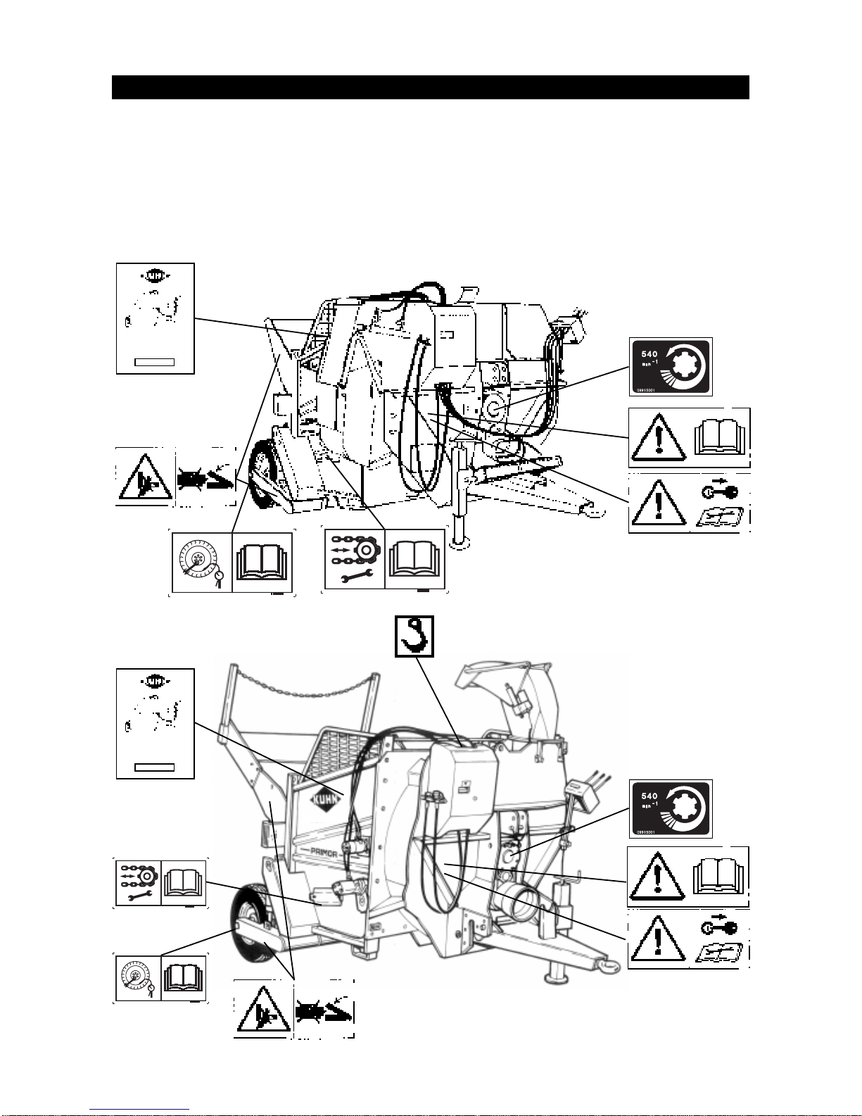
LABELS RELATING TO SAFETY
Adhesive labels have been placed on your machine as represented below. Their object is to contribute
to your safety and to that of others as well as to the correct operation of the machine. Read their
contents and check their location. Read the labels, as well as the instructions contained in the user
manual, with the operator of the machine.
Keep the labels clean and legible. Replace them when they become damaged.
PRIMOR
straw blower
PRIMOR
straw blower
Page 13

13
CHECK CHAIN TENSION REGULARL Y
CHECK REGULARL Y THE TYRES PRESSURE AND
THA T WHEEL NUTS ARE TIGHT
AL WA YS KEEP YOUR HAND A W A Y FROM THE
CRUSHING AREA UNTIL ALL MOVING P ARTS ARE A T
A COMPLETE ST ANDSTILL
BEFORE CARRYING OUT ANY MAINTENANCE ON
THE MACHINE, SWITCH OFF THE TRACTOR
ENGINE, REMOVE THE KEY FROM THE IGNITION
AND WAIT UNTIL ALL MOVING P ARTS HA VE
STOPPED
BEFORE COMMISSIONING THE MACHINE, READ
THE INSTRUCTION MANUAL AND THE RULES OF
SAFETY
Page 14
14
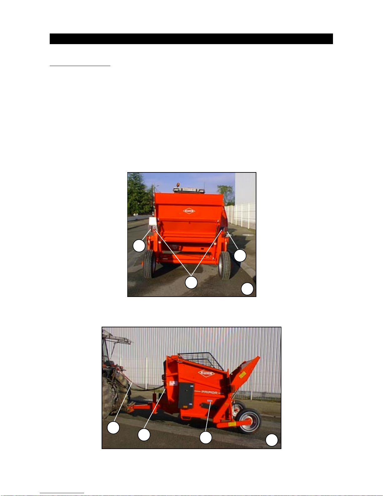
TRAILED PRIMOR
N.B. This equipment is fitted as standard on trailed machines in accordance with current legislation.
The equipment includes:
- 1 RH tail light (A) (Photo 1)
- 1 LH tail light (B) (Photo 1)
- 2 reflective triangles (C) (Photo 1)
- 2 self-adhesive white reflectors (D) (Photo 2)
- 4 self-adhesive amber reflectors (E) (Photo 2)
- 1 premounted wiring harness (F) (Photo 2)
LIGHTING EQUIPMENT
2
E
F
D
B
C
A
1
Page 15

15
NOTES
Page 16
16
2
4
5
10
1
7
3
9
8
11
14
17
12
16
18
13
15
19
6
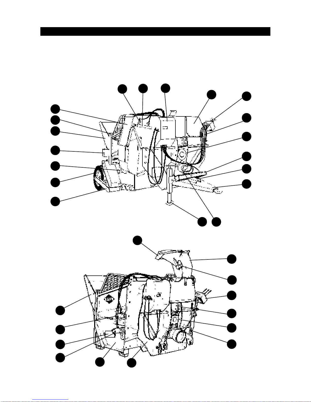
DESCRIPTION STRAW BLOWER PRIMOR
2
23
21
24
14
12
26
4
27
1
25
22
20
Page 17

17
1 - Turbine
2 - Control unit
3 - Remote control lines
4 - Gearbox
5 - Yoke
6 - Drive shaft support
7 - Tow bar
8 - Shaft protection bowl
9 - Parking stand
10 - Axle
11 - Wheel
12 - Chain tension inspection flap
13 - Tail light
14 - Gate
15 - Lifting point
16 - Side chute
17 - Flow limiters
18 - Chute ram
19 - Control box
20 - Swivel chute cap
21 - Swivel chute
22 - Electric cap ram
23 - Top link yoke
24 - Bottom point lock
25 - Conveyor drive motor
26 - Beater bar drive motor
27 - Body
Page 18

18
TECHNICAL SPECIFICATIONS
Mounted PRIMOR
Mounted straw blower and distributor.
Hydraulic loading and distribution system drive.
REP. DEFINI T I ON PRI M O R Mo u nted
PRIMOR Mounted
w ith pivoting chute
A Overall widt h when chut e c l os ed m 2,25 2,07
A1 Overall widt h when c hut e open m 3,00
2,25
Overall lengt h (mac hi ne on ground)
B1 Door on ground m 3,26
3,26
B2 Door closed m 2,68
2,68
C Overall height (mac hine on ground) m 1,81
2,50
E Lateral overhang, c hut e s i de m 1,30
1,12
F Lat eral overhang, left hand side m 0,95
0,95
G Internal l ength of hopper m 1,81
1,35
H Internal widt h of hopper m 1,55
1,55
I Internal height of hopper m 0,90
0,90
J Minimum c oupli ng height m 0,30
0,30
Blowing di s t anc e
St andard PRIMOR m 18
12 to 15
St raw blower / c hopper PRIMO R PH m 0 to 8
Spreading height
L* Min. m 0,43
2,02
max. m 1,43
2,50
Unladen weight in work ing order kg 1250
1250
Capacit y m3 3
3
Payload kg 950
950
Min. power required
Blowing HP/ k w 70/51
70/51
Chopping HP / kw 80/59
80/59
Tractor press ure required bar Min. 150 - Max. 180
Min. 150 - Max. 180
Tractor output min. l/m i n 25/30
25/30
Tractor output max . l/m i n 45
45
* Depending on tractor (take account of lifting height)
The electrical control option is only factory-fitted.
Optional equipment:
- Chute type Standard PRIMOR on straw chopper PRIMOR PH
- Linkage bar cat. 2/3
- Rectangular bales kit.
Page 19

19
Page 20

20
TECHNICAL SPECIFICATIONS
REF. DEFINITION P RIMOR Traile d
PRIM OR Trailed w ith
pivoting chute
A O verall width (chute clos ed) m 2,38 2,20
A1 Overall width (chute open) m 3,12
2,25
Overall length (mac hine on ground)
B1 Door on ground m 4,10
4,10
B2 Door closed m 3,55
3,55
M ax. room required in height
D1 * M achine on ground m 1,98
D2 * Ax le at max . height m 2,64
E Lateral overhang, chute side m 1,30
1,12
F Lateral overhang, left-hand side m 1,06
1,06
G Internal length of hopper m 2,30
2,30
H Internal width of hopper m 1,55
1,55
I Internal height of hopper m 0,90
0,90
J Minim um c oupling height m 0,20
Blowing distanc e
Standard P RIMO R m 18
12 to 15
St raw blower / c hopper PRIM OR P H m 0 to 8
Spreading height
L* M in. m 0,55
2,10
Max. m 2,00
2,49
M Gauge m 1,78
1,78
N Wheelbase m 3,26
3,26
Normal transportation height m 0,50
0,50
Unladen weight in working order k g 1650
1650
Total laden weight k g 2600
2600
Capacity m 3 3
2
Pay load kg 950
950
Tyres 185/75X14
185/75x14
Tyre press ure bar 2,40
2,40
M in. power required
Blowing HP /k w 50/36
50/36
Chopping HP /k w 80/59
80/59
Tractor press ure required bar Min. 150 - M ax. 1 80
M in. 150 - Max . 180
Tractor output m in. l/min 25/30
25/30
Tractor output m ax . l/min 45
45
* Depending on tractor (take account of lifting height)
The electrical control option is only factory-fitted.
Optional equipment:
- Chute type Standard PRIMOR on straw chopper PRIMOR PH
- Wide angle PTO shaft - Rectangular bales kit.
Semi-Mounted PRIMOR
Semi-mounted straw blower and distributor.
Hydraulic loading and distribution system drive.
Page 21

21
Page 22

22
DESCRIPTION OF THE CONTROLS
TELEFLEX CABLES REMOTE CONTROLS
Raising and lowering the chute:
First lever starting from the left.
By pushing the lever, the chute points upwards.
By pulling the lever, the chute points downwards.
The speed of motion of the chute is selected using two flow limiters
placed on the chute ram. For adjustment, unlock the limiters (N°2 hexagon
key) then select the speed by turning the knobs.Tightening the knob slows
down the movement of the chute. Slackening it off speeds up this
movement.
Raising and lowering the box body (only on semi-mounted
PRIMOR)
Second lever starting from the left.
By pushing the lever, the box body descends.
By pulling the lever, the box body rises.
Raising and lowering the gate:
Third lever starting from the left.
By pushing the lever, the door descends.
By pulling the lever, the door rises.
Rotation of the beater and belt chain conveyor
Fourth lever starting from the left.
By pulling the lever, beater and bed chain conveyor will move forward.
By pushing the lever, beater and bed chain conveyor will move backward.
Page 23

23
Adjusting the speed of belt chain conveyor
Switch situated at the bottom right-hand side of the control box.
Warning !It is absolutely essential to switch on the indicating lamps in
order to power the electrical circuit which regulates the belt chain
conveyor.
Positioning the switch to the left increases the speed of the belt chain
conveyor.
Positioning the switch to the right decreases the speed of the belt chain
conveyor.
The speed of the belt chain conveyor is graduated from 0 to 10 in
increasing speed. This is illustrated on the front part of the machine.
Swivel chute
Push the switch up to rotate the chute to the right.
Push the switch down to rotate the chute to the left.
Raising and lowering the swivel chute cap
Push the switch to the left to raise the cap.
Push the switch to the right to lower the cap.
Page 24

24
ELECTRICAL CONTROL
Raising and lowering the chute and the box body:
First lever starting from the left.
When the lever is up, the box body descends.
When the lever is down, the box body rises.
When the lever is to the right, the chute descends.
When the lever is to the left, the chute rises.
Raising and lowering the gate:
Second lever starting from the left.
When the lever is up, the arm descends.
When the lever is down, the arm rises.
Rotation of the beater and belt chain conveyor
Third lever starting from the left.
When the lever is to the left, the belt rotates in the spreading direction.
When the lever is to the right, the belt rotates in the opposite direction
Adjusting the speed of belt chain conveyor
Switch situated at the bottom right-hand side of the box.
Positioning the switch to the left increases the speed of the bed
chain conveyor.
Positioning the switch to the right decreases the speed of the bed
chain conveyor.
The speed of the bed chain conveyor is graduated from 0 to 10
increasing speed.This is illustrated on the front part of the machine (in this case, the switch lights up).
Page 25

25
Powering the box
Switch situated at the bottom left hand side of the box
When the switch points to the left, the controls are in neutral
When the switch points to the rightn the controls are active (in this
case, the switch lights up)
Swivel chute
Push the switch to the right to rotate the chute to the right.
Push the switch to the left to rotate the chute to the left.
Raising and lowering the swivel chute cap
Push the switch to the left to raise the cap.
Push the switch to the right to lower the cap.
Page 26

26
STARTING UP
A
B
The Primor are supplied with a safety system fitted to the delivery chute ram. The purpose of this
system is to lock the chute ram for transport in total safety.
The system consists of a metal bar restricting
the two shafts of the chute ram and clamps
which must be removed when the machine is
commissioned.
The bar must be removed before any attempt is made to open the chute.
Removal procedure
- Take the clamps (A) of f the bar.
- The bar (B) should come freely away from its
seat.
For your safety, never try to
pull the bar by hand.
- Operate the hydraulic control of the delivery
chute to close it fully .
The bar should now come freely away from its
seat.
Page 27

27
HITCHING
Trailed PRIMOR
Before hitching the machine, make sure that there is sufficient ballast on the
front axle of the tractor.
Ballast should be added to the special supports according to the tractor
manufacturer’s instructions. The front axle load must be not be less than
20% of the unladen tractor weight.
For road transport, hitch the machine on to the tractor eye bolt – cf. Fig. 1
- Using the parking stand, set the towing eye to the same height as the eye bolt.
- Back up the tractor, then lift the parking stand to hitch the machine to the tractor.
- Lock the hitch with the special device.
For use on the farm, hitch the machine to the tractor lifting system – cf. Fig. 2
- Fit the drawbar (1) onto the lifting arms.
- Lock the drawbar (1) with 10 mm clips (2) (not supplied).
- Back up the tractor until the towing eye is lined up with the pin hole in the drawbar.
- Insert a 150 mm long, 28 mm dia. retaining pin (not supplied).
- Once the machine is coupled up, stabilise the drawbar laterally with the special devices provided
(bar, chain, chocks, etc.).
Switch off the tractor engine before carrying out any operations between the
machine and the tractor.
Couple the hitch safety cable to a fixed point on the tractor.
Fig. 1 Fig. 2
Page 28

28
2
Mounted PRIMOR
The Primor is equiped as standard with linkage arm cat 2.
- Position the lower link on the lifting arm.
- Lock the lower link with the aid of the pins provided for this purpose (photo 1).
- Machine on the ground, bearing firmly, reverse the tractor until the link is totally engaged with the
coupling of the machine.
- After having stopped the engine of the tractor, adjust the length of the third point so that the machine
stays well on the ground (photo 3).
- Set up the axle of the third point (photo 3).
- With the machine now coupled, laterally stabilize the 3 points blower link using the device provided
for this purpose (bar, chain, shims, etc...) (photo 4)
1
Page 29

29
4
3
Page 30

30
ADJUSTING THE POSITION OF THE CONTROLS
Remote control cables
There are two types of control unit mounting:
. Mounting the unit on the machine.
This is designed for mounting the control unit when the machine is uncoupled from the tractor.
. Mounting the unit on the tractor
The machine is supplied with a control unit bracket for self-assembly . It is best fitted on the
lower crossbar in the rear opening of the cab (see photos below).
Electric control unit
The user may choose the location for the unit.
Page 31

31
TRANSMISSION
Working Parts (PTO and universal drive shafts)
Carefully read the instructions supplied with the transmission.
1. Only use universal drive shafts supplied with the machine or recommended by the manufacturer.
2. The PTO and universal drive shaft guards must always be fitted and in good condition.
3. Make sure that there is correct tube overlap on the universal drive shafts, both in the working
position and the transport position. Adjust the length of the tubes if necessary .
4. Before connecting or disconnecting a universal drive shaft, disengage the PTO, switch off the
engine and remove the key from the ignition.
5. Always make sure that the universal drive shafts are properly fitted and secured.
6. Make sure that the universal drive shaft guards are prevented from rotating by the special chains.
7. Before engaging the PTO, make sure that the speed setting and direction of rotation comply with
the manufacturer’s instructions.
8. Before engaging the PTO, make sure that there are no persons or animals near the machine.
9. Never engage the PTO with the tractor engine switched off.
10. Disengage the PTO whenever the universal drive shaft angle limits indicated by the manufac-
turer are in danger of being exceeded.
11. Beware! After disengaging the PTO, moving parts continue to rotate for a few seconds. Keep
away until they have stopped.
12. On unhitching the machine, rest the universal drive shafts on the special supports.
13. When the universal drive shaft has been disconnected from the tractor PTO, refit the protective
cap.
14. Any damaged PTO and universal drive shaft guards must be replaced immediately.
15. Beware! Only use the machine with a PTO speed of 540 min
-1
.
16. Any action on the lift function may damage the transmission.
17. Check that the overload clutch is working properly. After a period of inactivity, disassemble and
clean the clutch (see the transmission instructions supplied with the machine).
Page 32

32
UNIVERSAL DRIVE
- At maximum extension, there must be a tube overlap of A = 330 mm (Fig. 4).
- At maximum overlap (with the drive shaft compressed), there must be a safety gap of B = 20 mm to
prevent the tubes striking the jaws (Fig. 4).
- If the above conditions are not met, shorten the guards (1) and the tubes (2) by the same length (X)
(Fig. 5).
- Round off and clean the tubes and grease the inside of the outer tube.
- Always make sure that the universal drive shafts are properly fitted and secured.
- Any damaged PTO and universal drive shaft guards must be replaced immediately.
Make sure that the drive guards are properly fitted and prevented from rotating by the special chains. Replace any damaged guards immediately.
Consult the operating and maintenance instructions enclosed with the drive
shaft.
Fig. 4 Fig. 5
Page 33

33
CONNECTIONS
Hydraulic
(Machines not equipped with an auxiliary unit)
The machine requires a double-acting hydraulic distributor with an independent lift function. The
machine’s hydraulic circuit operates at a maximum pressure of 180 bar.
The pressure hose is equipped with a screw-in valve.
The return hose is equipped with a female push-pull coupler ( ISO 7241).
Connect the distributor supply hoses to the tractor. The pressure hose (P) is identified by a white
arrow on a red background, with the arrow pointing away from the tractor towards the distributor. The
return hose (T) is identified by a white arrow on a blue background, with the arrow pointing away from
the distributor towards the tractor.
- The hydraulic connection to the tractor may be made in one of three ways:
1 - Single-acting distributor pressure and direct return to tank (certain models of John Deere
tractor require a return to the header).
2 - Double-acting distributor pressure and return to second orifice of the same distributor (beware
of direction of oil flow).
3 - Pressure on line to be followed from tractor distributor and return to tank.
- Plug in the hoses. Make sure that the hoses cannot catch while in operation.
- If the machine distributor is connected to the original tractor distributor, activate the relevant handle
on the tractor distributor to pressurise the hydraulic circuit (beware of direction of oil flow).
Electrical Working voltage: 12 V olts.
Keep all lighting clean and in good condition. Repair any damaged or
malfunctioning lights immediately.
Before taking out onto public roads, check that all lighting is in good working
order.
- Plug the lighting equipment into the standardised 7-pin socket at the rear of the tractor.
Page 34

34
Electrical
The electric power cable (2) is not supplied mounted.
Connect this cable to the + and - terminals on your tractor battery.
Then connect the switch box to the cable (2) to activate the controls.
The switch box is equipped with a 16 Amp fuse (1).
PRELIMINARY CHECKS
. Hydraulic and electrical connections. Make sure that the pressure and return hoses are
properly connected
. Machine securely hitched to tractor
. No loose components
. Hydraulic hoses
. Chain tension.
. Choice of fan speed.
. Drive shaft length.
. Oil level in fan drive unit.
. Oil level in conveyor drive unit.
Page 35

35
NO-LOAD TESTS
Do not stand in the working area of the machine.
Before starting up, the user must familiarise himself with the machine’s
operating controls and their respective functions. Once work has begun, it
will be too late.
Before starting up the machine, check around the machine (beware of
children!). Make sure that you have sufficient visibility .
Keep people and animals away from the danger area of the machine.
In the case of a “free wheel” PTO shaft, the fan may continue to run for around
two minutes after the PTO has come to a complete standstill.
- Test each control in both directions: beater bars, turbine, chute, axle und rear lifting door.
- Check the hydraulic circuit for leaks.
- Test the lighting and signalling system (side lights, brake lights and turn-signal indicators).
UNHITCHING
- Before unhitching the machine, switch off the tractor engine and remove the key from the ignition.
- Lay the machine on the ground so that it is stable.
- Before unhitching the machine, bring the grab inside the body and lower the arm completely (ram
rods fully retracted).
- Uncouple the hydraulic pressure and return hoses and the electrical connections.
- Apply the machine’s parking brake.
- Remove the hitch safety cable.
- Unhitch the machine.
Page 36

36
MACHINE OPERATION
Read carefully before starting up the machine.
The machine must be used by one person only.
Before starting up the machine and beginning work, check around the machine
(beware of children!). Make sure that you have sufficient visibility .
Keep people away from the danger area of the machine.
Beware! When operating the loading components (arm, grab, machine body),
make sure that there can be no accidental contact with a power line.
Never stand beside the distribution chute while the machine is in operation.
Before starting up, check that the machine is in good condition, the tension of
the chains is correct, the components are properly greased and the screws
are tight.
Before commencing any manoeuvres in reverse gear or operating the loading
gear, sound the horn twice.
1. LOADING BALES
Before loading a bale (round or rectangular), position it in the good direction ie:
- round bale: in the unrolling direction
- rectangular bale: the strings must be at the side of the bale
- It is recommended to make the bale supported by a strongly built obstacle (wall, post). Never use a
pile of bales as a support. There is a risk of collapse.
- Couple the machine (see the Chapter on “Starting up” ).
- Using the control levers, lower the gate as close as possible to the ground (see the Chapter on
“Descriptions of controls”)
- Position together the tractor/machine exactly in the axis of the bale.
- Reverse slowly until the gate slides under the bale. Make sure the bale is well centered.
- Keep reversing until the bale is safely on the gate.
- Raise the gate until the bale is in a stable position.
- Stop the engine. Remove the ignition key.
- Cut the strings around the bale.
Page 37

37
When cutting the strings, the engine must be stopped and the ignition key
removed.
Cutting the strings is made from the outside of the machine. In any case, the
operator must not climb into the machine or on the bale to cut the strings.
- When the strings are removed, raise the arm until the bale is in contact with the beater bar. Never
“press” the bale on the beater bar.
2. SPREADING
Always start up the power take-off before operating beater and/or bed chain
conveyor.
Always stop the belt chain conveyor before stopping the power take-offs.
In case of a Primor straw blower/chopper or a rectangular bale kit, check the
regulation speed control of the bed chain conveyor is at minimum.
- Start up the power take-off ( use only 540 min
-1
power take off).
- Put up the distribution chute in the required position.
- Start up the bed chain conveyor and the beater bar (see the Chapter on “Description of controls”).
- To variate the straw flowrate, make the moving speed variate (engine power).
- In case of a PRIMOR straw blower/chopper or a rectangular bale kit, the regulation of the flowrate
can be done thanks to the divertor valve.
- As the bale diminishes in diametre, raise the gate, without pressing the bale.
- If the flowrate is too important, and to avoid blockage of the machine, stop the belt chain conveyor,
wait a few seconds and then start it up again.
- When straw distribution is over, stop the beater bar and conveyor, close the delivery chute, close the
gate, disengage the PTO and switch off the tractor engine.
Pay attention to the direction of rotation of the beater bar and of the bed chain
conveyor. A loaded machine operating for too long in reverse may become
seriously damaged.
Never attempt to free the product by hand or with a tool (fork, etc...) when the
machine is operating.
Never climb into the machine or enter the box body when the machine is
operating.
During the chopping in a closed place (poultry house), use a tractor with a
cabin. The operator must wear individual protection (anti-noise, helmet,
glasses,...).
Page 38

38
3. TRANSPORTATION
The transportation of individuals or animals on the machine during operation
or whilst in motion is stricly forbidden.
Respect the maximum authorized width for driving on public roads.
Before joining public roads, check that the protective and signalling devices
required by law are installed and operating correctly .
The speed and method of driving must always be adapted to the type of ground,
roads and tracks. Avoid abrupt changes in direction under all circumstances.
Steering precision, roadholding of the tractor, behaviour on the road and
effectiveness of the breaking devices are influenced by factors such as weight
of the coupled machine, ballast on the front axle, state of the ground or road
covered.
Disconnect the power take-off and wait until the turbine has stopped rotated
completely (up to 2 min).
Note: Should the turbine or beater bar become jammed, use the hook mounted on the right-hand
side of the machine (see photo below) to pull out the jammed product at the distribution chute or
beater bar, then use a lever to ensure that the turbine can rotate freely.
Page 39

39
OPTIONS
The optional equipment is compatible with the machines as shown in the table below:
OPTIONS Mounted PRIMOR
Semi-mounted
PRIMOR
PRIMO R with
pivoting chute
Electrical control
XXX
Wide angle PTO shaft
XX
Rectangular bales kit
XXX
Chute type of standard PRIMOR on straw blower /
chopper PRIMOR PH
XX
Sealed floor
XX
The option electrical control is only fitted at factory.
Before fitting optional equipment to the machine, respect these few rules:
- check that the equipment received actually corresponds to the equipment ordered.
- check the contents of the parcel with the aid of the list given in the manual.
- read carefully the assembly and usage manual for the equipment.
Beware!
WHEN CLEARING A BLOCKAGE OR REPLACING A WORKING PART, WEAR
PROTECTIVE GLOVES AND ONLY USE APPROPRIATE TOOLS.
To fit the options, you will need to use a variety of handling equipment and tools.
Refer to the safety instructions for such equipment before use.
The machine must be unhitched from the tractor before assembling an option.
Before assembling an optional device with the machine or one of the machine’s
loading components in the raised position, prop up the machine or the component
with an appropriate support.
If lifting gear (block and tackle, elevator, etc.) is used to handle the machine, only
use the specially provided lifting hooks shown by a pictogram.
Page 40

40
SAFETY
Before carrying out any maintenance, servicing or repair work or when
investigating the cause of a failure or malfunction, switch off the engine, remove
the ignition key and wait for all moving parts to come to a complete standstill.
Before proceeding with any maintenance work on a machine in the raised
position, prop up the machine with an appropriate support.
When replacing a working part, wear protective gloves and only use appropriate
tools.
To avoid environmental contamination, it is forbidden to throw away or dump
any type of oil, grease or filter. Hand them over to specialist recovery firms.
Before carrying out any operations on the electrical circuit, disconnect the
power source (tractor battery or charging circuit).
Any protective devices liable to wear should be checked regularly. Replace
them immediately if they are damaged.
Spare parts must comply with the standards and specifications laid down by
the manufacturer. Only use KUHN spare parts.
Page 41

41
WIDE ANGLE PTO SHAFT
- PTO shaft providing a greater angle of deflection.
Please read the manual supplied with the PTO shaft carefully.
CAT. 2/3 LINKAGE BAR
- Wide linkage bar (750 mm)
See the chapter on “Starting up: Hitching”.
STRAW BLOWING CHUTE ON PRIMOR STRAW BLOWER / CHOPPER
- Can be fitted on PRIMOR straw blower / chopper to increase blowing distance. It is
installed instead of the standard chopping chute.
Respect the general safety instructions and the maintenance instructions.
Page 42

42
REGULATING COMBS FOR RECTANGULAR BALES
Devices to avoid clogging of the straw in the turbine.
DESCRIPTION
- 3 off-regulating combs
- 6 washers M10
- 6 bolts M10X20
ASSEMBLY
Assemble according to the diagram below.
Page 43

43
MAINTENANCE
BEFORE CARRYING OUT ANY MAINTENANCE, SERVICING OR REP AIR
WORK OR WHEN INVESTIGATING THE CAUSE OF A FAILURE OR
MALFUNCTION, YOU MUST SWITCH OFF THE ENGINE, LAY THE MA-
CHINE DOWN, REMOVE THE IGNITION KEY AND WAIT FOR THE
MOVING PARTS TO COME TO A COMPLETE STANDSTILL.
Before proceeding with any maintenance work on a machine in the raised
position, prop up the machine with an appropriate support.
WHEN CLEARING A BLOCKAGE OR REPLACING A WORKING PART,
WEAR PROTECTIVE GLOVES AND ONLY USE APPROPRIATE TOOLS.
To avoid environmental contamination, it is forbidden to throw away or dump
any type of oil, grease or filter. Hand them over to collection firms.
Before carrying out any operations on the electrical circuit, disconnect the
power source (tractor charging circuit or battery).
Any protective devices liable to wear should be checked regularly. Replace
them immediately if they are damaged.
Spare parts must comply with the standards and specifications laid down by
the manufacturer. Only use KUHN spare parts.
Before carrying out any electrical welding work on the tractor or towed machine, disconnect the cables from the alternator and battery.
Check the tightness of screws and nuts regularly. Tighten up if necessary.
Page 44

44
CONVEYOR CHAIN TENSION
- To be checked every 150 hours. If the sag exceeds 150 mm, tighten up the chains (see Figure 1).
- To tighten the chains:
. Remove the two covers (A) (Figure 1).
. Tap the plate (2) lightly to free the screws (1) (Figure below).
. Tighten the screws (B) equally to obtain the required tension (Photo 2).
. Refit the two covers (A).
. Never fully tighten the chains. Always leave at least 50 mm of sag.
Figure 1
Photo 2
2
3
Photo 3
4
Photo 1
A
1
Page 45

45
TYRES
- Before any intervention on the tyres, make sure that the trailer is perfectly stabilized and cannot
move accidentally ( fit chocks).
- The fitting, removal and repair of wheels and tyres must be carried out only by those who have the
necessary knowledge and possess the required tools.
- Regularly check the tyre pressure! Comply with the manufacturer recommended pressure.
- Regularly check that the wheel nuts are tight.
The set up of tyres can be:
OIL CHANGE AND LEVEL CHECK
The oil needs to be changed in:
. the gearbox (figure 1)
. the conveyor reduction gear unit (figure 2).
Regularly check the oil level to ensure tat the gearbox suffers no abnormal damage.
1 - Draining and filling the gearbox
(see Figure 1)
Draining:
- Remove the fill plug (17 mm wrench).
- Place a container under the drain hole and remove the drain
plug (17 mm wrench).
Filling:
- Refit the drain plug (replace the seal if necessary).
- Remove the level gauge plug (17 mm wrench). Fill the gearbox
using a funnel. Capacity: 5 litres of SAE 90 (ISO 150) oil (e.g.
Shell Omala 150).
- Stop filling as soon as oil seeps through the level gauge hole.
- Refit the level gauge plug and fill plug.
TYRES TYRE PRES S URE MAX. CHARG E BY TYRE
185/75 x 14 2,4 bar 835 k g
205/75 x 15 2,4 bar 1035 kg
235/75 x 15 3,5 bar 1300 kg
Fig. 1
Filling plug
Drain plug
Level gauge
plug
Page 46

46
Filling plug
Drain
Level
Figure 2
- The conveyor reduction gear unit (Figure 2)
. Change the oil after the first 50 hours of work, then every 1500 hours thereafter.
. Check the oil level in the conveyor reduction gear unit regularly (every 200 hours).
. We recommend an SAE 90 oil, e.g. Shell Omala 150. Reduction gear capacity: 0.5 litre.
Page 47

47
After 1
hour
After
50
hours
Every
50
hours
Every
100
hours
After
500
hours
Every
500
hours
Every
1500
hours
Every
2000
hours
or
every
year
Tighten wheel bolts (100 N.m)
XX
Tighten drawbar eyebolts
XX
Grease gate joint
XX
Grease swivel chute bearing
XX
Grease ax le joint
XX
Grease chute rams
XX
Grease gate rams
X X
Grease chute ram join
XX
Grease ax le rams
XX
Grease beater bar bearing
XX
Grease driv e chain (ST D)
XX
Grease conv eyor shaft bearing
XX
Grease parking stand
XX
Change conv eyor reduction gear oil
XX
Change gearbox oil
XX
Change hy draulic unit oil
XX
Change hy draulic unit f ilter car t ridge
XX
Check convey or chain tension
XX
Check convey or reduct ion gear oil level
XX
Check gearbox oil lev el
XX
MAINTENANCE SCHEDULE
Beware! The schedule indicated below has been calculated for normal conditions of use. If the
working conditions prove more difficult, grease more often.
PTO shaft: for the maintenance period, refer to the instructions supplied with the PTO shaft.
Page 48

48
STORAGE:
- If the machine is not to be used for a long period, prepare it for storage.
- Clean the hopper (inside, outside and below), the chute, the arm with a jet of water. Remove all
accumulating product. You may repaint all surfaces that may rust. Lubricate the bottom of the belt
chain.
When cleaning using pressure, it is necessary to pay attention to sensitive zones (axle points,
electrical connections ...).
- Put the axle pins back to preserve them from humidity and dust.
- Grease drive chain.
- Clean all the lubricating points and joints and lubricate again.
- As far as possible, garage your machine under a shelter, on blocks, to isolate it from humidity from
ground.
- Check the tyre pressure and the tightening of the gudgeons.
Page 49

49
TROUBLESHOOTING
PROBLEMS POSS IBLE CAUSES W HAT TO DO
Loading difficultie s
Hydraulic problem . Check that the hy draulic c onnect ion
between the tractor and the mac hine is
c orre ct (p ress ure a nd ret u rn ).
. As k your dealer to check the hy draulic
pressure (180 bar) and the pump flow
(30 l/min.). Return pressure m ust be 8 bar
max im um at nom inal trac tor engine speed.
Distribution difficulties
Imposs ible to distribute:
. Turbine fails to rotat e, overload
clu tc h s lipping
Turbine jamm ed . S wit c h off the trac tor engine an d dis engage
the tractor PTO (see the Safety Precautions
section).
. Check that product has n’t built up in the
turbine. If this is the cas e, us e the hook
mounted on the right-hand side of the
mac hine to pull out the jam m ed product at
the distribution chute or beater bar, then us e
a lever to ens ure that the turbine can rotate
freely. Onc e releas ed, run th e turbine em p ty
for a few seconds until it reaches its norm al
working speed.
. The turbine is rotating and the
beater bar is moving forwards
Conveyor set to 0 . Set conveyor speed to appropriate mark
(see D es c ript ion of Cont rols sec t ion).
Beater bar jamm ed . Decompress t he product ins ide the body
with the gate.
. Swit ch the c onveyor briefly to reverse and
then back t o forward motion.
Insufficient beater bar
and conveyor power
. S ee "What to do" t o resolve a hy draulic
problem in the s ec t ion on loadin g difficulties .
Insufficient gate power
Page 50

50
PROBLEMS POSSIBLE CAUSES WHAT TO DO
Turbine rat tli ng when P TO engaged Clutch sl ipping
intermittently
. Graduall y engage the P TO to a suitable
speed. If your machine is equi pped wi th a
free-wheel drive s haft and your tractor with a
hydr aulic PTO clutch, refer to your deal er
(probl em with progres sive clutch rate
irrespective of tractor engine speed).
Clutch movement too slow or
impossible
Flow limiters not open
enough
. Adjust flow limiters (see Description of
Controls section).
Mac hine empty or
nearly empty and
discharge convey or
running
Stop conveyor to manœuvre chute.
Clean and grease the swivel chute.
Chute movement too qui ck Fl ow lim iters open t oo
far
. Adjust flow limiters (see Description of
Controls section).
Page 51

51
GENERAL CONDITIONS OF WARRANTY
KUHN-AUDUREAU S.A., B.P . 19, 85260 LA COPECHAGNIERE, FRANCE (hereinafter referred to as the Company) hereby certifies in accordance with the provisions stated below to each original purchaser of new
equipment manufactured by Kuhn-Audureau that said equipment is, at the time of delivery to the user,
guaranteed against all construction faults and manufacturing defects, provided that the equipment in question
is used and maintained in accordance with the instructions contained in the accompanying manual.
This warranty covers our equipment for a period of one year from the date of delivery or for 500 hours of
operation, whichever is the shorter.
The date of the invoice to the final purchaser and the return of the warranty card by the dealer to the Company, with the signature of the dealer and the purchaser, will indicate delivery of the equipment.
The warranty is limited to a money-back guarantee or to the repair at our factory and by our Engineering
Departments of parts which are recognised to be faulty in terms of material or craftsmanship.
F The following exceptions shall apply however:
- Parts included in the composition of machines but which are not manufactured by Kuhn-Audureau, such as
tyres, transmission assemblies, overload clutches, hydraulic rams, hydraulic distributors, etc., are not
covered by the Kuhn-Audureau warranty but by the respective manufacturer’s warranty.
- Claims relating to such parts will be handled in the same way as if they were Kuhn-Audureau parts.
However compensation will depend on the warranty agreement of the manufacturer concerned, insofar as
the latter acknowledges the validity of the claim. Obviously the warranty does not apply if the faults are due
to normal wear and tear, deterioration or accidents resulting from negligence or inadequate supervision,
misuse, lack of maintenance and/or if the machine has been damaged in an accident, lent or used for a
purpose other than the one intended by the Company.
- Obviously the warranty does not apply if the faults are due to normal wear and tear, deterioration resulting
from negligence or inadequate supervision, misuse, lack of maintenance and/or if repairs have not been
carried out by an approved dealer.
- The warranty is void if alterations have been made to the machine without the express agreement of the
Company or if anything other than OEM parts have been fitted to machine sold by the Company and/or if
repairs have not been carried out by an approved dealer or distributor.
- The Company cannot be held responsible for damage suffered by the machine or its accessories during
transport and handling by any carrier, even outside the legal warranty period. Machines, machine parts or
accessories are carried at the risk of the addressee.
- The Company will not be responsible in the case of a claim or injury involving the owner or a third party, or
for the resulting liability.
- Similarly, the Company cannot be held to pay any compensation whatsoever for the loss of a harvest or any
damages whatsoever due to a flaw, latent defect or breakdown of the machine.
F The User is responsible for and shall bear all costs relating to:
- routine servicing of the equipment, including lubrication, supervision and maintenance of oil levels, minor
adjustments, etc.;
- the labour required to remove and replace a faulty part or parts and, if necessary, adjustments of the
corresponding new part or parts;
- the dealer’s call-out charge;
- the transport of machines, machine parts or accessories to the place of repair and the return of the elements
in question to the place of use;
- wear parts, such as belts, tyres, bed chains, knives, teeth, overload clutches, etc., which are not covered by
the warranty.
Page 52

52
F The warranty is subject to strict compliance with the following provisions:
- Commissioning of the equipment by the dealer in accordance with our instructions.
- Return of the warranty certificate duly signed by the dealer and user on commissioning.
- Claims shall only be made on a Kuhn-Audureau claim form and sent by the dealer to the Company within a
period of one month of the date of the incident.
- The claim form shall be completed in a legible manner by the dealer and must include the following informa-
tion:
. the dealer’s name, address and customer code
. the purchaser’s name and address
. exact type of machine
. serial number of the machine
. date of delivery to the purchaser
. date of incident
. number of hours of use
. power of tractor used
. detailed description and presumed cause of the incident
. quantities, references and names of the damaged parts
. date and number of the invoice for replacement parts.
- Damaged parts are to be returned by the dealer to the Company for examination together with the duplicate
of the claim form. Transport costs relating to the return of said parts are to be met by the sender.
- The machine must be serviced and used in accordance with the instruction manual. Only the quantity and
grade of lubricants recommended by the Company must be used.
- The safety measures mentioned in the instruction manual and on the machine itself must be observed and
all protective elements and guards, of any nature whatsoever, must be inspected regularly and kept in
perfect condition.
- The Company’s decision, irrespective of the subject of the warranty claim, is final and the purchaser agrees
to accept it.
- If the warranty claim is rejected, the dealer has two weeks from the date of receipt of our letter of notification
in which to request the return of the damaged parts. Once this period has elapsed, they will automatically be
destroyed.
F Further conditions: limits of application and responsibility
- The warranty cannot be assigned or transferred to any person without the Company’s prior written consent.
- Our approved dealers have neither the right nor the power under any circumstances to make any decision,
either expressly or tacitly, on behalf of the Company.
- The technical assistance provided by the Company or its agents with regard to the repair or operation of
equipment does not involve the Company’s responsibility in any way and shall not under any circumstances
introduce a novation or waiver to the conditions of this warranty.
- The Company reserves the right to modify its machines without notice. It will not however be responsible for
applying such changes to machines already sold or in service.
- Furthermore, due to the constant evolution of technology, no guarantee can be given with regard to the des-
cription of equipment provided in any literature issued by the Company.
- This warranty is exclusive of any other express or implicit responsibility of the Company, either legal or by
agreement. The responsibilities of the Company may not under any circumstances exceed those defined
hereinbefore.
Page 53

53
THIS EQUIPMENT COMPLIES WITH THE LABOUR CODE
THE MANUFACTURER DECLINES ALL RESPONSIBILITY SHOULD USE OF THE
EQUIPMENT NOT COMPLY WITH THE RECOMMENDATIONS CONTAINED IN THIS
MANUAL.
THE USER SHALL OBSERVE HEALTH AND SAFETY RULES AND
AGRICULTURAL INSURANCE FUND RECOMMENDATIONS.
OUR SAFETY RULES AND ADVICE ARE NOT RESTRICTIVE.
Page 54

54
KUHN-AUDUREAU
BP 19 - F - 85260 LA COPECHAGNIERE (FRANCE)
TEL +33 (0)2 51 41 47 00
FAX +33 (0)2 51 41 41 03
www.kuhnsa.com
info@kuhnsa.com
As it is our policy to make constant improvements to our products,
the characteristics contained in this manual, which are correct on the date
of publication, may be changed at any time without notice
or contestation.
All apparatus in the Kuhn-Audureau range comply with the standards of
the French Ministry of Labour laid down in decree n° 86594 of 14 March 1986
and the departmental order of 14 March 1986.
 Loading...