

Page 1

OPERATOR'S MANUAL
GN007AGB C
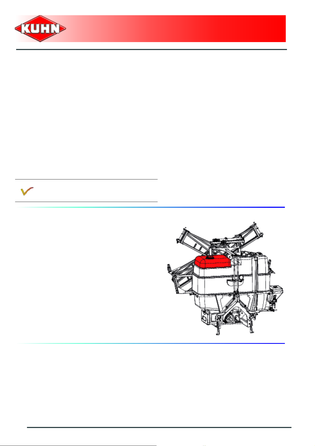
Mounted field sprayers
OMNIS
GN007AGB C
- English - 06-2010
Page 2

Page 3

Mounted field sprayers
OMNIS
$Dear Owner
In buying a Kuhn machine you have chosen wisely. Into it have gone years of thought, research and
improvement. You will find, as have thousands of owners all over the world, that you have the best that
engineering skill and actual field testing can produce. You have purchased a dependable machine, but only
through proper care and operation can you expect to receive the performance and long service built into it.
This manual contains all the necessary information for you to receive full efficiency from your machine. The
performance you get from this machine is largely dependent on how well you read and understand th is manual
and apply this knowledge. Please DO NOT ASSUME YOU KNOW HOW TO OPERATE AND MAINTAIN YOUR
MACHINE before reading this manual carefully. KEEP THIS MANUAL AVAILABLE FOR REFERENCE. Pass
it on to the next owner if you re-sell the machine.
Your KUHN dealer can offer a complete line of genuine KUHN service parts. These parts ar e manufactured and
carefully inspected in the same factory that builds the machine to assure high quality and accurate fitting of any
necessary replacements.
About improvements
We are continually striving to improve our products. It therefore reserves the right to make improvements or
changes when it becomes practical to do so, without incurring any obligations to make changes or additions to
the equipment sold previously.
Designated use of the machine
The OMNIS sprayer must only be used for the work for which it has been designed:
- The spraying of liquid products used in the agricultural field on low cultivations.
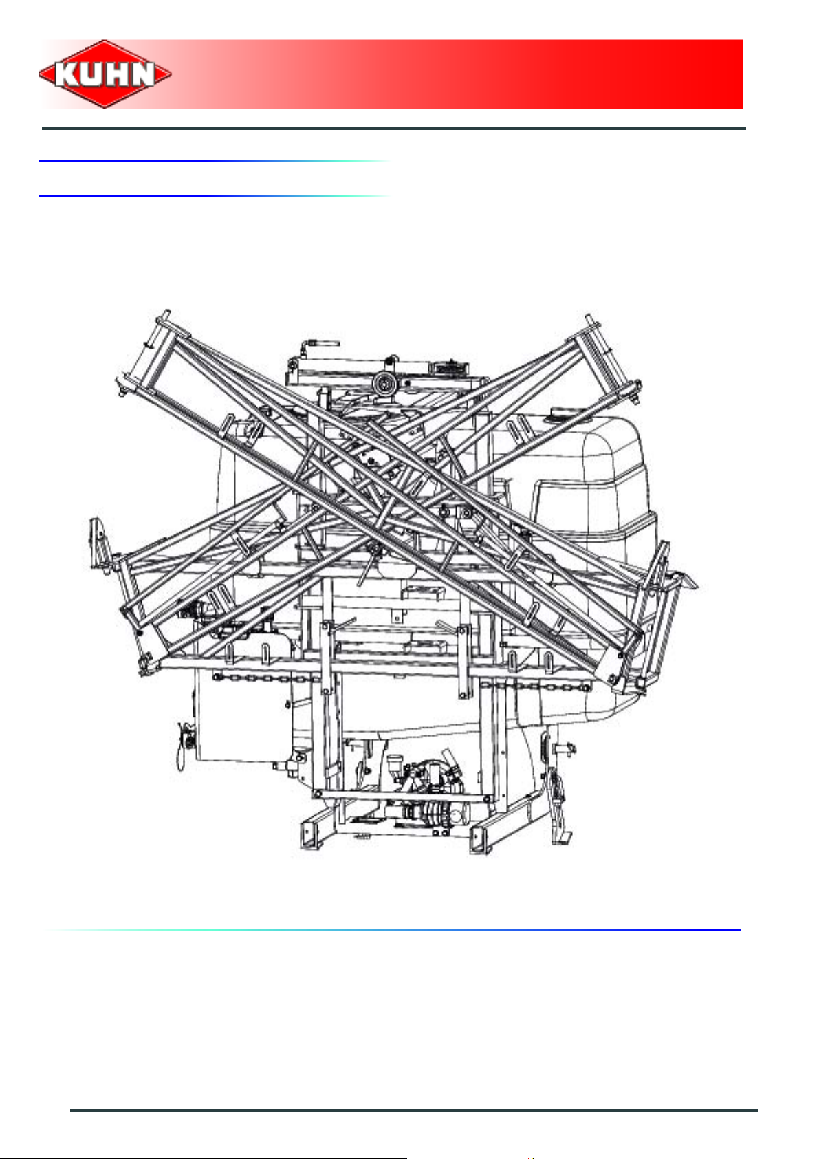
Document illustrations
The illustrations in this manual are based on one machine model and in a given configuration.
Dear Owner
1
Page 4

Mounted field sprayers
OMNIS
$Contents
Dear Owner.....................................................................................................................1
Contents..........................................................................................................................2
Identification of the machine.........................................................................................5
Front view..........................................................................................................................................5
Rear view.. .......................................... ... .... ... ... .......................................... ... ... .... ... ... ........................6
Model identification plate ................................................................................................................7
Optional equipment..........................................................................................................................8
Safety.............................................................................................................................10
Description of symbols used in this document...........................................................................10
Safety instructions.........................................................................................................................11
Location and description of safety decals on the machine .......................................................25
Road safety equipment and recommendations...........................................................................29
Machine specifications................................................................................................30
Description and glossary...............................................................................................................30
Technical specifications................................................................................................................33
Technical specifications per model..............................................................................................35
Water circuit....................................................................................................................................36
Booms .............................................................................................................................................38
Circulation.......................................................................................................................................39
Required equipment.......................................................................................................................43
2
Sound levels ......... ... ... .... ... ... ... .... ............................................. ......................................................56
Contents
Page 5

Mounted field sprayers
Putting into service ..................................................................................................... 57
Description of control elements ......... ... ... .... ... ... ... .... ... ... ... .... ... ... ... ... .... ... ... ................................57
Description of the section valves.................................................................................................60
Description of the box AE .............................................................................................................62
Description of the box DPS...........................................................................................................64
Description of the box RPB...........................................................................................................66
Description of the box RSB3/REB3 ..............................................................................................68
Description of the box CH10.........................................................................................................70
Description of the valves...............................................................................................................72
Coupling and uncoupling.......... .... ... ... ... ... .... ... ... ... .... ... ... ... .... ... ... ................................................74
Instructions for transport............................................................................................ 91
OMNIS
Putting the machine into transport position................................................................................91
Conformity with the road regulations ... ... .... ... .............................................................................97
Instructions for work...................................................................................................98
Putting the machine into work position............. ..........................................................................98
Adjustments in working position................................................................................................103
Groundspeed................................................................................................................................106
Machine use ...............................................................................................................107
Steps (optional)............................................................................................................................107
The tanks.......................................................................................................................................108
Incorporator (optional)................................................................................................................. 114
Spraying........................................................................................................................................119
Rinsing (optional) . ... ... ... .... ... ............................................. ... .... ... ... ..............................................120
Outer discharge............................................................................................................................124
Emptying the tank................................... ... .... ... ... ... .... ............................................. ....................125
Contents
3
Page 6

Mounted field sprayers
OMNIS
Optional equipment....................................................................................................126
Spray offset on boom end...........................................................................................................126
Cleaning the machine on the outside.........................................................................................128
Second tractor equipment...........................................................................................................129
Pipe pressure gauge....................................................................................................................130
Filling hose....................................................................................................................................130
GPS speed sensor........................................................................................................................130
Tank gyrocleaner.. ... ... .... ... .......................................... ... ... .... ... ... ... .... ... .......................................131
Foam marker............... .... ... ... ............................................. ...........................................................137
Flashing light................................................................................................................................137
Control box DPI ............................................................................................................................138
Emptying valve on section end...................................................................................................139
Storage compartment ....... ... ... .... ... ... ... .... ... ... ... ...........................................................................141
Quick coupler................................................................................................................................141
Automatic hitch (EASY HITCH) ...................................................................................................142
Maintenance and storage..........................................................................................152
Frequency chart.............................. ... ... .... ... ... ... ............................................. ..............................152
Lubrication....................................................................................................................................154
Maintenance..................................................................................................................................157
Storage..........................................................................................................................................165
Machine recycling ................................................ .............................................. ..........................166
Trouble shooting guide..............................................................................................167
Description of fuses............. ... .... ... ... ... .... ............................................. ... ... ... .... ..........................171
Appendix.....................................................................................................................176
Calculating the load on an axle...................................................................................................176
Limited warranty.........................................................................................................181
4
Contents
Page 7

1. Front view
Mounted field sprayers
OMNIS
$Identification of the machine
Identification of the machine
5
Page 8
2. Rear view
Mounted field sprayers
OMNIS
6
Identification of the machine
Page 9

3. Model identification plate
Please write below the type and serial number of the
machine. This information is to be indicated to the dealer
for all spare parts orders.
Mounted field sprayers
OMNIS
Type:
Serial no.:
Identification of the machine
7
Page 10

4. Optional equipment
All equipments listed below are not always
compatible between each other or with your
machine.
See machine corresponding to a specific
configuration.
Check with your authorized KUHN dealer the
equipment compatibility with your machine.
Tick box corresponding to the equipment fitted on your
machine:
Spray offset on boom end
Kit no. 1356177: Manually controlled jet offset on boom end to the left
Kit no. 1356178: Manually controlled jet offset on boom end to the right
Kit no. 1356179: Manually controlled jet offset on double boom end
Kit no. 1356180: Electrically controlled jet offset on boom end to the left
Kit no. 1356181: Electrically controlled jet offset on boom end to the right
Kit no. 1356182: Electrically controlled jet offset on double boom end
Mounted field sprayers
OMNIS
Cleaning the machine on the outside
Kit no. 1356199: 15 m (49’2’’) Automatic reel and spray gun
Kit no. 1346319: 15 m (49’2’’) automatic reel and spot spray gun
Second tractor equipment
Kit no. 1346085: Control box attachment bracket
Kit no. 1346086: Speed sensor
Pipe pressure gauge
For models equipped with boom RHX:
Kit no. 1346293: Pipe pressure gauge
For models equipped with boom RVA:
Kit no. 1346294: Pipe pressure gauge
For models equipped with boom RPL / RJP2:
Kit no. 1346315: Pipe pressure gauge
8
Identification of the machine
Page 11

Sundry
Kit no. 1346027: Filling hose
Kit no. 1346186: GPS speed sensor
Kit no. 1346089: Tank gyrocleaner
Kit no. 1346314: Foam marker
Kit no. 1346013: Flashing light
Kit no. 1346007: Control box DPI
Kit no. 1346244: Emptying valve on section end
Kit no. 1346318: Storage compartment
Kit no. 1346269: Quick coupler.
Kit no. 1346317: Automatic hitch (EASY HITCH)
Mounted field sprayers
OMNIS
Identification of the machine
9
Page 12

$Safety
1. Description of symbols used in this document
This symbol indicates a potentially hazardous situation
that if not avoided, could result in serious bodily injury.
Mounted field sprayers
OMNIS
This symbol is used to identify special instructions or
procedures which, if not followed strictly, could result in
machinery damage.
This symbol is used to communicate technical
information of particular interest.
10
Safety
Page 13

Mounted field sprayers
OMNIS
2. Safety instructions
Introduction
The machine must only be operated, maintained and repaired by competent persons who are familiar with
machines' specifications and operation and aware of safety regulations fo r preventing accidents.
The operator must imperatively respect safety instructions in this manual and in the warnings posted on the
machine. The operator is also obliged to respect current le gislation concerning accident prevention, wo rk safety
and public traffic circulation.
Designated use of the machine also means following operation, maintenance and repair recommendations
given by the manufacturer, and using only genuine spare parts, equipment a nd acce sso ries, as r ecom mended
by the manufacturer.
The manufacturer is not held liable for any damage resulting from machine applications other than those
specified by the manufacturer. Any use other than the designated operation is at the risk and responsibility of
the operator.
The manufacturer is not held liable for any damage or accident re sulting from machine modifications carried out
by the operator himself or by a third party without previous written agreement from the manufacturer.
-
Read and follow the safety instructions
Before using the machine, carefully read all the safety
instructions in this manual and the warnings placed on
the machine.
Before starting work, the operator must be familiar with
all machine controls, handling devices and their
functions. It is too late to learn once work has been
started!
Never let anyone operate the machine who is not traine d
to do so.
Should you have any difficulties in understanding certain
parts in this manual, please contact your KUHN dealer.
Precautions to be taken before carrying out
any operations on the machine
Before leaving the tractor or before adjusting,
maintaining or repairing the machine, disengage the
PTO drive, turn off the engine, remove ignition key and
wait until all moving parts have come to a complete stop
and apply park brake.
Safety
11
Page 14

Precautions to take before using the
machine
Ensure that all operating controls (ropes, cables, rods,
etc) are placed so as they cannot be operated
unintentionally and cause damage or injury.
Prior to each machine use, ch eck tigh tness o f bolts and
nuts, in particular those securing the tools (booms,
wheels...). Retighten if necessary.
Before operating the machine, ensure that all the safety
guards are firmly in place and in good condition.
Immediately replace any worn or damaged guard.
Precautions when driving
Tractor handling, stability, performance and braking
efficiency are all affected by weight distribution, trailed or
mounted implements, additional ballast and driving
conditions. It is therefore of great importance that the
operator exercises caution in every given situation.
Groundspeed must be adapted to ground conditions as
well as to roads and paths. Always avoid abrupt change s
of direction.
Be particularly cautious when turning corners, paying
attention to machine overhang, length, height and
weight.
When the main tank is full, reduce travel speed to limit
rolling movement in the tank.
Never use a narrow track tractor on very uneven or
steeply sloping ground.
Never leave the tractor seat while the machine is
operating.
Carrying people or animals on the machine when
working or in transport is strictly forbidden.
Mounted field sprayers
OMNIS
12
Safety
Page 15

Maximum speed
Always keep to the legal speed limit for driving a tractormachine assembly on public roads.
Precautions when driving on public roads
Always obey current regulations for driving
on roads
Dimensions
Depending on the dimensions of the machine, contact
the relevant authorities to ensure that it can be legally
transported on public roads.
If the machine is over the maximum legal size, follow the
local regulations for special transportation of oversize
equipment.
Mounted field sprayers
OMNIS
Transport position
Before transporting the machine on public roads, place
the machine into its transport position, according to the
instructions in this manual.
Lights and indicators.
Before transporting the machine on public road s, ensure
that all legally required lightings and signallings are in
place.
Ensure that lightings and signallings are clean and in
good working order. Replace any missing or broken
equipment.
Safety
13
Page 16

Mounted field sprayers
Gross weight and weight per axle
The drawings are not legally binding, their only aim is to illustrate the method to use.
Prior to driving on public roads, check that criteria a re met to be in conformity with th e countrie's
regulations:
- When coupling a tool to the front and rear 3-point lift linkage, the maximum authorized
payload must not be exceeded.
- When coupling tools to the front and rear 3-point lift linkages, the maximum load on each
axle's tires must not be exceeded.
- The load on the tractor front axle must always represent 20 % of the tracto r unladen weight.
For machines with hoppers or tanks:
- If the total unit weight exceeds the tractor Gross Combined Weight Rating in accordance
with the countrie's legislation, empty the hopper to travel on public roads.
- In any case, we recommend to travel on public roads with empty hoppers and tank s.
OMNIS
Description of symbols
Description Units Description
T kg Tractor unladen weight
PTAC kg Gross Combined Weight Rating
T1 kg Unladen load on tractor front axle
T2 kg Empty load on tractor rear axle
t kg Axle loads (Tractor + machine)
t1 kg Load on front axle (Tractor + machine)
t2 kg Load on rear axle (Tractor + machine)
t1 max kg Maximum load authorized on the tractor front axle according to the tires
t2 max kg Maximum load authorized on the tractor rear axle according to the tires
M1 kg Total weight of front tool or front ballast
14
Safety
Page 17
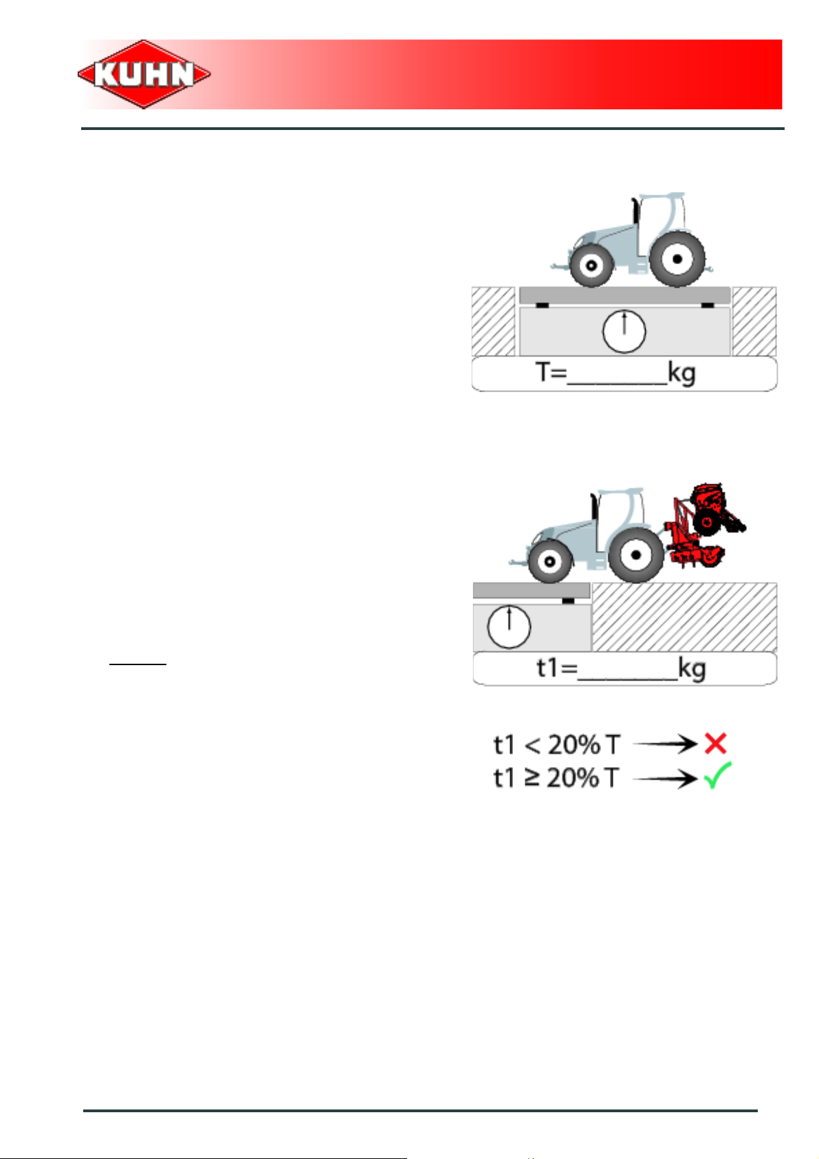
Stage 1:
To measure:
- Tractor tare (T).
Mounted field sprayers
OMNIS
Stage 2:
- Couple the machine to the tractor.
To measure:
- Load on front axle (t1):
• Tractor + machine (transport position).
To do:
- If the front axle load (t1) is below 20% of the tractor
tare (T), add ballast weights (M1) to exceed the
minimum load on the front axle.
Example:
• (T) = 7500 Kg (16535 lb)
• The front axle load must be of minimum 1500 Kg
(3300 lb).(20% of T)
• (t1) = 700 Kg (1545 lb).
• 700 Kg (1545 lb) < 1500 Kg (3300 lb).
• Add ballast weights until the minimum front axle
load is exceeded.
• Repeat checking procedure.
Safety
15
Page 18
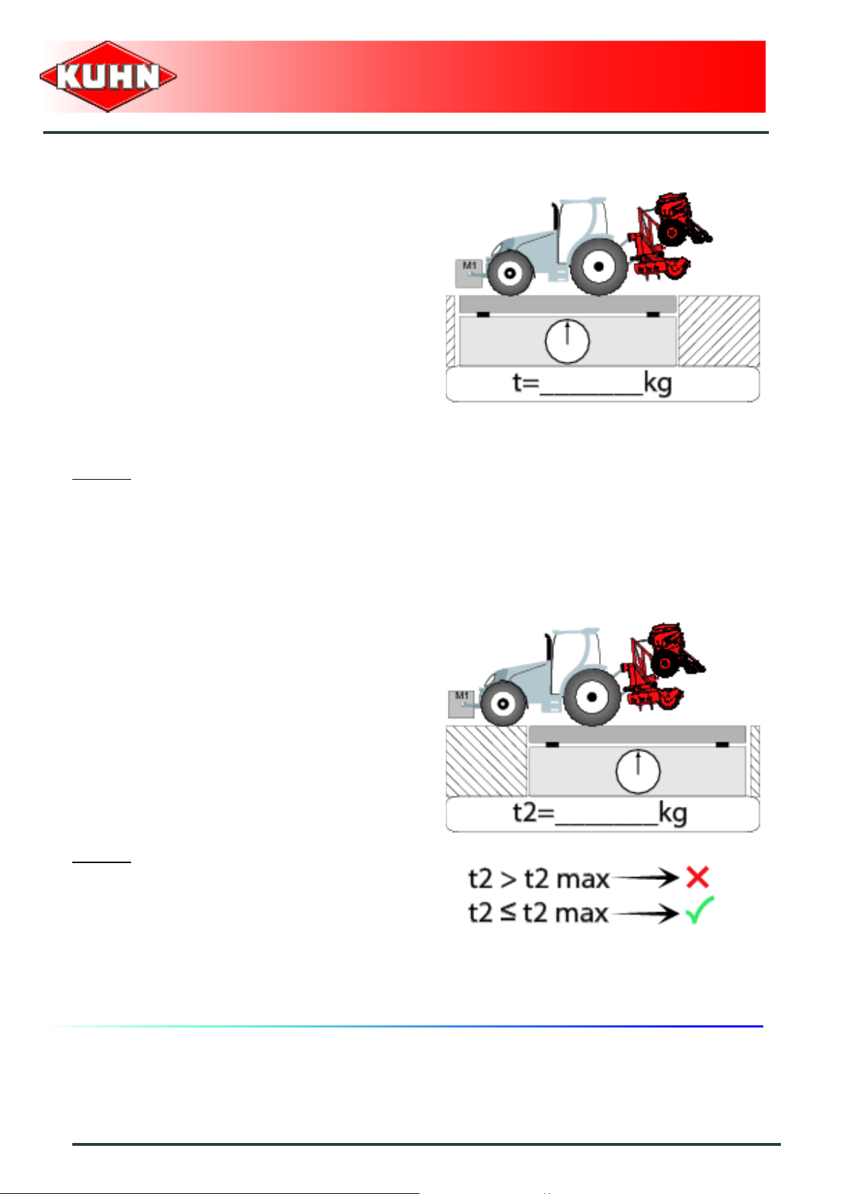
Stage 3:
To measure:
- Total weight (t):
• Tractor + machine (transport position).
• Ballast weights.
Checking:
- To go to the next stage:
• Check in the tractor's operator's manual that the
value measured is below the tractor's Gross
Combined Weight Rating.
To do:
- If t < PTAC go to the next stage.
- If the total unit weight exceeds the tractor Gross
Combined Weight Rating in accordance with the
countrie's legislation, empty the hopper to travel on
public roads.
Example:
• (t) = 10000 Kg (24250 lb)
• PTAC = 13000 Kg .
• t < PTAC : Go to the next stage.
Mounted field sprayers
OMNIS
Stage 4:
To measure:
- Load on rear axle (t2):
• Tractor + machine (transport position).
• Ballast weights.
Checking:
- Check in the tractor's operator's manual that the value
measured is below the maximum allowed tractor rear
axle load.
- Check that tyre and rim specifiations are in conformity
with the requirements of the tractor manufacturer.
Example:
• Load on rear axle (t2) = 8500 Kg (18740 lb)
• Check in the tractor's operator's manual that the
value measured is below the maximum allowed
tractor rear axle load.
• Check that tyre and rim specifiations are in
conformity with the requirements of the tractor
manufacturer.
16
Safety
Page 19

Precautions when coupling
Prior to coupling the machine, check that it can't move
unexpectedly (place wedges underneath the wheels or
lock handbrake) and that the parking stand is the the
adequate position.
Never stand between the tractor and the machine when
operating the three point linkage.
Do not stand between the tractor and the machine
without ensuring that the parking brake is applied.
Hydraulic circuit
Caution! The hydraulic circuit is under high pressure.
Maximum pressure at work: 200 bar.
Before connecting hoses to the tractor hydraulics,
ensure that tractor and machine circuits are not under
pressure. Before disconnecting a hose, depressurize the
hydraulic circuit.
To avoid making incorrect connectio ns, mark hydraulic
couplers and corresponding hoses with colors.
WARNING! Functions could be reversed (for example:
lift/lower) and cause accidents.
Regularly check the hydraulic hoses. In case of normal
wear, replace the hydraulic hoses every 5 years.
Damaged or worn hoses must immediately be r eplaced.
When replacing the hydraulic hoses, only use hoses with
the specification recommended by the manufacturer of
the machine.
To locate a leak, use appropriate means. Protect body
and hands from liquid under pressure.
Any liquid under pressure (particularly oil from
hydraulics) can penetrate the skin and cause severe
injury. If injured, see a doctor immediately, there could
be danger of infection. Before any adjustments,
maintenance or repairs are carried out, lower the
machine to the ground, depressurize the hydraulics, turn
off the engine, remove ignition key and wait until all
moving parts have come to a complete stop.
Mounted field sprayers
OMNIS
Safety
17
Page 20

PTO shaft
Use only PTO shafts supplied with the machine or
recommended by the manufacturer.
The protective shield of the tractor PTO stub, the PTO
shaft guards and the protective covering of the machine
input shaft must always be in place and in good
condition.
Make sure that the PTO shaft guards are secured with
the safety chains provided.
Any worn or damaged guards must be replaced
immediately. A worn guard or an unpro tecte d PTO shaft
can cause a serious or even a lethal accident.
Do not wear loose clothing that could be caught in the
rotating PTO shaft.
Before attaching or removing a PTO shaft, or before
doing any work on the machine, disengage the PTO
drive, turn off the engine, remove ignition key and wait
for all moving parts have come to a complete stop.
If the primary PTO shaft is equipped with a slip clutch or
a free wheel, these must be fitted on the machine side.
Ensure that the PTO shaft is always correctly fitted and
locked into place.
Before connecting the PTO shaft, ensure that the PTO
speed (rotational frequency) and directions of rotation
are in line with manufacturer's recommendat ion s.
Before engaging the PTO drive, make sure all people
and animals are clear from the machine. Never engage
the PTO drive when the tractor engine is stopped.
When uncoupling the machine, rest the PTO shaft on the
support specially provided, and replace protective cover
on the PTO stub of the tractor.
Read and follow the instructions in the operator's manual
provided with the PTO shaft.
Mounted field sprayers
OMNIS
18
Safety
Page 21

Precautions during manoeuvres
When moving the machine from the transport position to
the working position and vice versa, make sure that
nobody is within the machine pivoting area.
Remote controlled components
Danger of crushing and shearing can exist when
components are operated by hydraulic or pneumatic
controls. Keep away from these danger zones.
Tyres
Regularly check the tyre pressure. Respect
manufacturers' recommendations on pressure.
Assembly, disassembly and repair of wheels and tyres
must only be carried out by competent persons who are
equipped with standardized tools. Before any work is
performed on the wheels, ensure that the machine rests
on the ground and is perfectly stable so that it cannot
move accidentally (put chocks in place).
Mounted field sprayers
OMNIS
Safety decals
Safety warning decals are placed in pictorial form on
various parts of the machine. They are there to warn you
of potential dangers and to tell you how to avoid
accidents.
Always keep the safety decals clean and readable, and
replace them when they are worn, damaged, missing or
illegible.
Waste disposal
Respect the environment! Never spill pollutants (oil,
grease, filters, etc.) on the ground, never pour them
down the drain and never discard them in any other
place where they could pollute the environment. Never
throw away or burn a tyre. Always take waste to
specialized recycling or waste disposal centers.
Safety
19
Page 22

Hydraulically controlled components
For machines fitted with a solenoid valve block
assembly, maintenance or rep air on the hydraulic blo ck
with emergency controls must be carried out by a KUHN
technician.
Hydro-pneumatic accumulator
A hydro-pneumatic accumulator contains nitrogen under
pressure (risk of suffocation in closed rooms).
Repairs, maintenance or commissioning may only be
carried out by competent persons. Wait for the
accumulator to cool down before hand ling it. Only use
nitrogen to precharge it.
Depressurize the gaz and oil sides of the hydraulic
accumulator before opening it.
It is strictly forbidden to weld, grind or drill onto a hydropneumatic accumulator.
Make sure that the accumulator and its' fittings are in
good condition.
Mounted field sprayers
OMNIS
Precautions to take before using the
control box
Place the control box so that it cannot interfere with other
tractor controls and be activated inadvertently.
Before switching the control box on, check that nobody
is within the machine pivoting area: switching on the
control box can activate functions on the machine.
Precautions to take when using the control
box
Do not operate the control box while a person is carrying
out work on the machine.
Switch off control box before carrying out any
maintenance or repair work on the machine.
20
Safety
Page 23

Precautions for maintenance and repair
work
Before leaving the tractor or before adjusting,
maintaining or repairing the machine, disengage the
PTO drive, turn off the engine, remove ignition key and
wait until all moving parts have come to a complete stop
and apply park brake.
Make sure that the parts of the machine that need to be
lifted for maintenance or repair work are firmly propped
up.
Before any work is done on the electric circuit or before
any electric welding is carried out on the attached
machine, disconnect the machine from the tractor
electrical circuit. Also disconnect alternator and battery
terminals.
Repairs on elements under pressure or tension (springs,
pressure accumulators, etc.) must only be carried out by
competent persons with regulation equipment.
Wear the appropriate protective clothing for the work in
hand (gloves, shoes, goggles, helmet, ear defenders,
etc.).
Do not solder, weld or use a blow torch near fluids under
pressure or inflammable products.
For your own safety and for correct machine operation,
only use original manufacturer parts.
It is strongly recommended to have your machine
checked by your Kuhn dealer after each season,
especially tools and their attaching hardware.
Mounted field sprayers
OMNIS
Safety
21
Page 24

Boom handling
Prior to handling the booms, check that overhead power
lines are at a safe distance.
If the machine comes into contact with a power line:
- Immediately stop the tractor, turn off the engine and
apply park brake.
- If possible, jump off the tractor withou t touching the
power lines.
- Immediately ask for the power line to be shut off.
- Never touch the machine until the power lines have
been disconnected from the power source.
- Warn any person not to touch the machine.
Toxic substances
Always have a first-aid kit within reach.
Avoid all skin, eyes and mouth contact with products
such as fuels, oils, solvents, antifreeze and cleaning
products. Most of them contain harmfull substances.
In case of an incident, seek medical advice.
Follow to the letter all instructions given on the safety
decals of toxic substance containers.
Mounted field sprayers
OMNIS
22
Safety
Page 25

Phytosanitary products
Keep phytosanitary products away from children.
During use of phytosanitary products, do not smoke or
eat.
Keep water taps and machine control components
clean, wash hands prior to handling them in conformity
with rules and regulations. Do not clean inputs, nozzles,
hoses or any other small parts by blowing with your
mouth.
Do not fill tanks with a sinking hose. Never connect
directly to the waterworks system for prepairing
treatments. Never pump water in natural environment
and do not pollute the environment.
Take the necessary precautions to prevent tank or
product spillage, outside the area to treat.
Comply with the product instructions and directions for
use. Beware of their noxiousness to wildlife and insects,
especially pollinating insects. Comply with the
instructions given in the directions of use, sa fety sheets
and advice documents.
Store crop protection products in a place with a leakproof
floor enabling to recover product leaks.
Rinse phytosanitary product containers and incorporate
the rinsing dilution in the sprayer tank, prior to the
treatment. Rinse and pierce packagings to prevent them
from being reused.
Spray at a minimum distance of ditch and river edges, in
conformity with rules and regulations in force.
The quantity of clear water added and/or the number of
tank rinse must be sufficient to divide the tank bottom
concentrate by at least 100.
Drain booms and tank bottoms on the treated cultivation
or on another authorized cultivation, preventing run-off.
Empty far from rivers, temporary pools, ponds, wells,
catch systems and residential areas.
In any case, conform with the current legislation.
Mounted field sprayers
OMNIS
Safety
23
Page 26

Body protection
Do not wear loose clothing which could become caught
up in moving parts.
Wear waterproof clothing whenever there is a risk of
splashing from or contact with crop protection products,
even in diluted form. Wear specific protective clothing
(suit, gloves, boots, glasses, mask) when handling
phytosanitary products).
Gloves
Wear gloves resisting to the various components
contained in the products (ultranitrile glooves).
Neoprene gloves are required in the presence of ketone
in the formulations.
Strictly avoid certain materials such as latex or PVC. A
watertightness indicator is insufficient.
Replace gloves as soon as they present signs of wear.
Store the gloves in a place well away from the products.
Mounted field sprayers
OMNIS
Protection suits
Use special protection suits resistant to the products.
Use preferably disposable coveralls.
Masks
Anti-dust masks do not protect sufficiently
against phytosanitary products.
Wear a respiratory protection when preparing the spray
mixture or spraying certain products.
Check that the respiratory protections are fitted with
filters.
Change cartridges every 40h during intensive use
periods.
Replace respiratory protection at least once per year.
24
Safety
Page 27
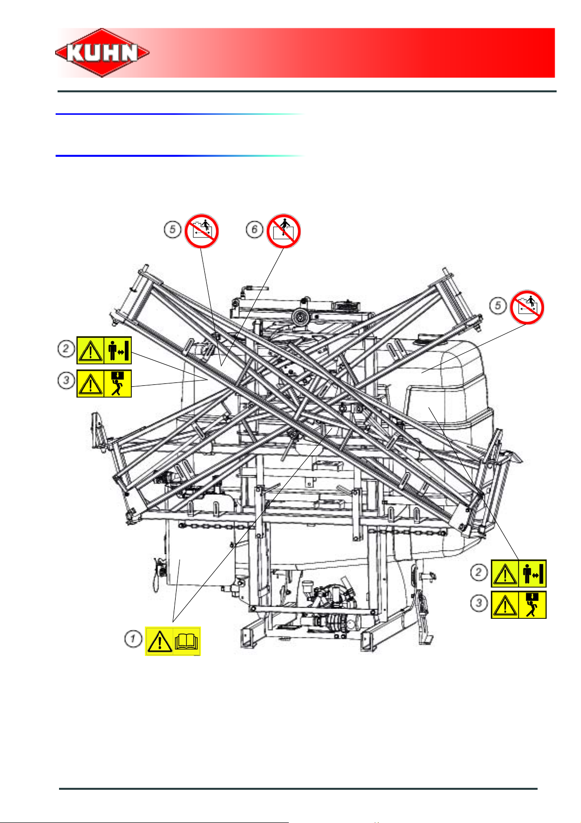
3. Location and description of safety decals on the machine
Location of safety decals
Mounted field sprayers
OMNIS
Safety
25
Page 28
Mounted field sprayers
OMNIS
26
Safety
Page 29

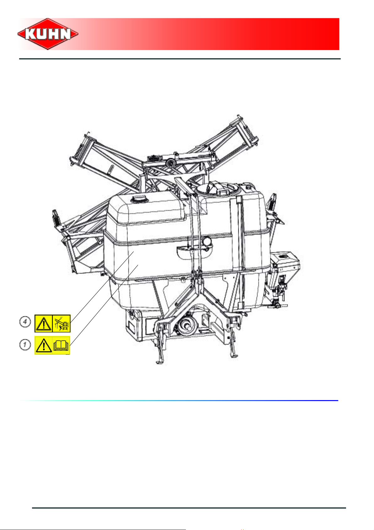
Description of safety decals
Operating instructions (1)
The operators' manual contains all the information
necessary for using the machine safely. It is imperative
to read and comply with all instructions.
Manoeuvring area (2)
Stay a safe distance from the machine.
Crushing hazard.
Mounted field sprayers
OMNIS
Body crushing (3)
Stay a safe distance from the machine.
Crushing hazard.
Safety
27
Page 30

Electric lines (4)
Before any machine unfolding/folding operation, check
that the electric lines are distant enough. There is a risk
of an electric shock and electrocution.
Passenger transport (5)
Never transport passengers on the machine.
Mounted field sprayers
OMNIS
Manhole (6)
Never enter in the tank.
28
Safety
Page 31

4. Road safety equipment and recommendations
The road safety equipment is mounted in the factory or
by your authorized Kuhn dealer according to current
safety regulations. Always keep to the legal speed limit
for driving a tractor-machine assembly on public roads.
The rear safety device comprises:
- 2 signalling lights (1) (red light / stop light / turn signal
light).
- A signalling panel (2).
Mounted field sprayers
OMNIS
The side device comprises:
- 2 signalling panels (1) (1 on each machine side).
Safety
29
Page 32

$Machine specifications
1. Description and glossary
0
Mounted field sprayers
OMNIS
1 : Boom 2 : Manhole
3 : Hand-wash tank 4 : Gauge
5 : Parking stand 6 : Coupling device
7 : Main tank 8 : Pressure gauge
30
Machine specifications
Page 33

Mounted field sprayers
OMNIS
0
1 : Boom suspension 2 : Central frame
3 : Central arm 4 : Second arm
5 : Third arm 6 : Outer arms
7 : Boom safety 8 : Section filter
9 : Nozzle holder 10 : Tubing
Machine specifications
31
Page 34

Mounted field sprayers
OMNIS
0
1 : Pump 2 : Suction filter
0
1 : Valve operating panel 2 : Suction
3 : Discharge
32
Machine specifications
Page 35

2. Technical specifications
Pump
Factory delivered with the following pumps:
Piston-diaphragm pump PM105:
Rotation speed
Maximum pressure
Nominal output
Piston-diaphragm pump PM125:
Rotation speed
Maximum pressure
Nominal output
Mounted field sprayers
OMNIS
540 min
15 bar (218 psi)
105 L/min (27.7 US gal/min)
540 min
15 bar (218 psi)
125 L/min (33 US gal/min)
-1
-1
Piston-diaphragm pump PM140:
Rotation speed
Maximum pressure
Nominal output
Piston-diaphragm pump PM165:
Rotation speed
Maximum pressure
Nominal output
The pump flow varies a ccording to the pressure. Th e higher the pressure, th e lower the flow. The lower the
pressure, the higher the flow.
140 L/min (37 US gal/min)
165 L/min (43.6 US gal/min)
540 min
15 bar (218 psi)
540 min
15 bar (218 psi)
-1
-1
Tank
Rinsing tank (optional)
Tank volume
Incorporator (optional)
Tank volume
100 L (26.4 US gal)
25 L (6.6 US gal)
Hand-wash tank
Tank volume
16 L (4.2 US gal)
Machine specifications
33
Page 36

Mounted field sprayers
Filter
Tank filling strainer 18 MESH
Suction filter (White) 32 MESH
Pressure filter
OMNIS
White
Blue
Red
Section filters
Blue
Red
Dimensions
Working position
Width
Length
Height
Transport position
Width
32 MESH
50 MESH
100 MESH
50 MESH
100 MESH
See boom chart
from 1.30 m to 1.65 m
(from 4’3’’ to 5’5’’)
2.30 m (7’7’’)
from 2.40 m to 2.55 m
(from 7’10’’ to 8’4’’)
Length
Height
34
Machine specifications
from 1.30 m to 1.65 m
(from 4’3’’ to 5’5’’)
from 2.30 m to 2.80 m
(from 7’7’’ to 9’2’’)
Page 37

Sundry
Mounted field sprayers
OMNIS
Coupling device
PTO speed 540 min
Hydraulic valve bank
Electro-hydraulic selector
Solenoid valve block
Regulation
The machine adapts to tractors fitted with a 3 point
linkage category 2.
from 1 to 3 functions
from 4 to 10 functions
DPM regulation (Directly proportional to motor)
DPME regulation (output proportional to engine
DPAE regulation (Ground speed related application
3. Technical specifications per model
-1
or
speed)
or
rate control)
Ground
Main tank
Nominal volume
Real volume
-
Ground
Main tank
Nominal volume
Real volume
OMNIS 600 OMNIS 800
from 400 kg to 960 kg
(from 882 lb to 2116 lb)
600 L (158.5 US gal)
635 L (167.7 US gal)
from 400 kg to 960 kg
(from 882 lb to 2116 lb)
800 L (211.3 US gal)
850 L (224.5 US gal)
OMNIS 1000 OMNIS 1200
from 400 kg to 960 kg
(from 882 lb to 2116 lb)
1000 L (264.2 US gal)
1080 L (285.3 US gal)
from 400 kg to 960 kg
(from 882 lb to 2116 lb)
1200 L (317 US gal)
1260 L (332.9 US gal)
Machine specifications
35
Page 38
4. Water circuit
0
Mounted field sprayers
OMNIS
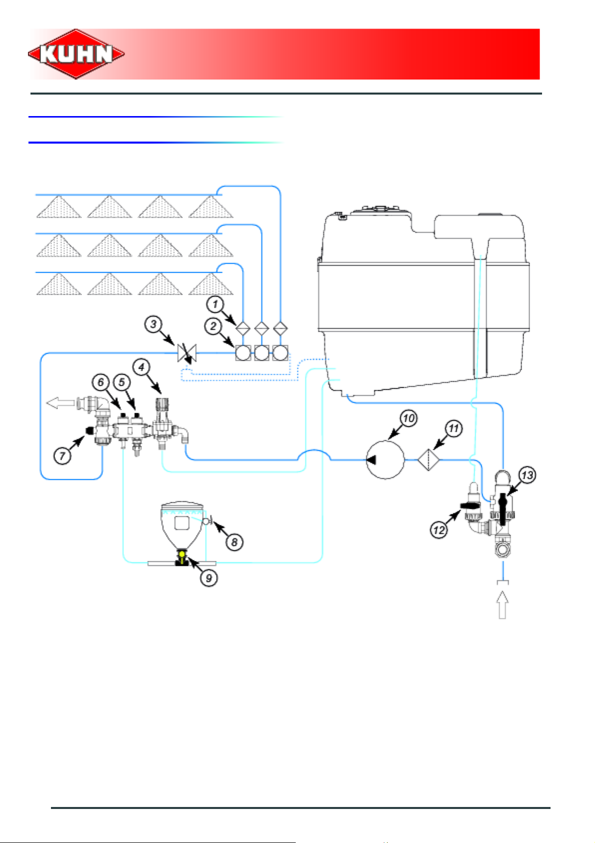
1 : Section filter 2 : Section valve
3 : Flow regulation valve 4 : BYPASS valve
5 : Accessory valve 6 : Product incorporator lever (optional)
7 : Discharge valve 8 : Incorporator rinsing valve
9 : Incorporation valve 10 : Pump
11 : Suction filter 12 : Rinsing tank valve (optional)
13 : Suction val ve
36
Machine specifications
Page 39

Mounted field sprayers
OMNIS
Operating principle
Pump (10) sucks up the liquid through suction filter (11). The valve lever position indicates the origine of the
liquid sucked by the pump:
-
- Suction valve (13):
• External suction.
• Main tank suction.
-
- Rinsing tank valve (12) (optional):
• Outer filling.
• Rinsing tank suction.
The pump supplies liquid to all spraying sections:
-
- BY-PASS valve (4) protects the overpressure circuit.
- Product incorporator lever (6) (optional).
- Discharge valve (7): The valve lever position indicates the destination of the liquid that has flown back from
the pump:
• Outer discharge.
• Booms.
Flow regulation valve (3) adjusts the boom flow by means of returning part of the liquid to the tank. The larger
the flow regulation valve opening, the high er the r eturn to tank. The smaller the flow regulation valve opening,
the lower the return to the tank.
When optional equipment is used, follow
specific procedures mentioned in the related
section:
- Tank gyrocleaner.
Machine specifications
37
Page 40

Mounted field sprayers
5. Booms
The machine is factory fitted with the following booms:
Sections
Manual boom RPL Working width
Manual boom RPL 9 9 m (29’6’’) 4 / 5 / 6
Manual boom RPL 10 10 m (32’10’’) 4 / 5 / 6
Manual boom RPL 12 12 m (39’4’’) 4 / 5 / 6
Manual boom RJP2 Working width
(for your
information)
Sections
(for your
information)
OMNIS
Manual boom RJP2 12 12 m (39’4’’) 4 / 5 / 6
Manual boom RJP2 15 15 m (49’3’’) 4 / 5 / 6
Manual boom RJP2 16 16 m (52’6’’) 4 / 5 / 6
Sections
Hydraulic boom RHX Working width
(for your
information)
Hydraulic boom RHX 12 12 m (39’4’’) 4 / 5 / 6
Hydraulic boom RHX 12,5 12,5 m (41’) 4 / 5 / 6
Hydraulic boom RHX 13 13 m (42’8’’) 4 / 5 / 6
Hydraulic boom RHX 15 15 m (49’3’’) 4 / 5 / 6
Sections
Hydraulic boom RVA Working width
(for your
information)
Hydraulic boom RVA 12 12 m (39’4’’) 4 / 5 / 6
Hydraulic boom RVA 13 13 m (42’8’’) 4 / 5 / 6
Hydraulic boom RVA 15 15 m (49’3’’) 4 / 5 / 6
Hydraulic boom RVA 16 16 m (52’6’’) 4 / 5 / 6
Hydraulic boom RVA 18 18 m (59’) 4 / 5 / 6
38
Machine specifications
Page 41

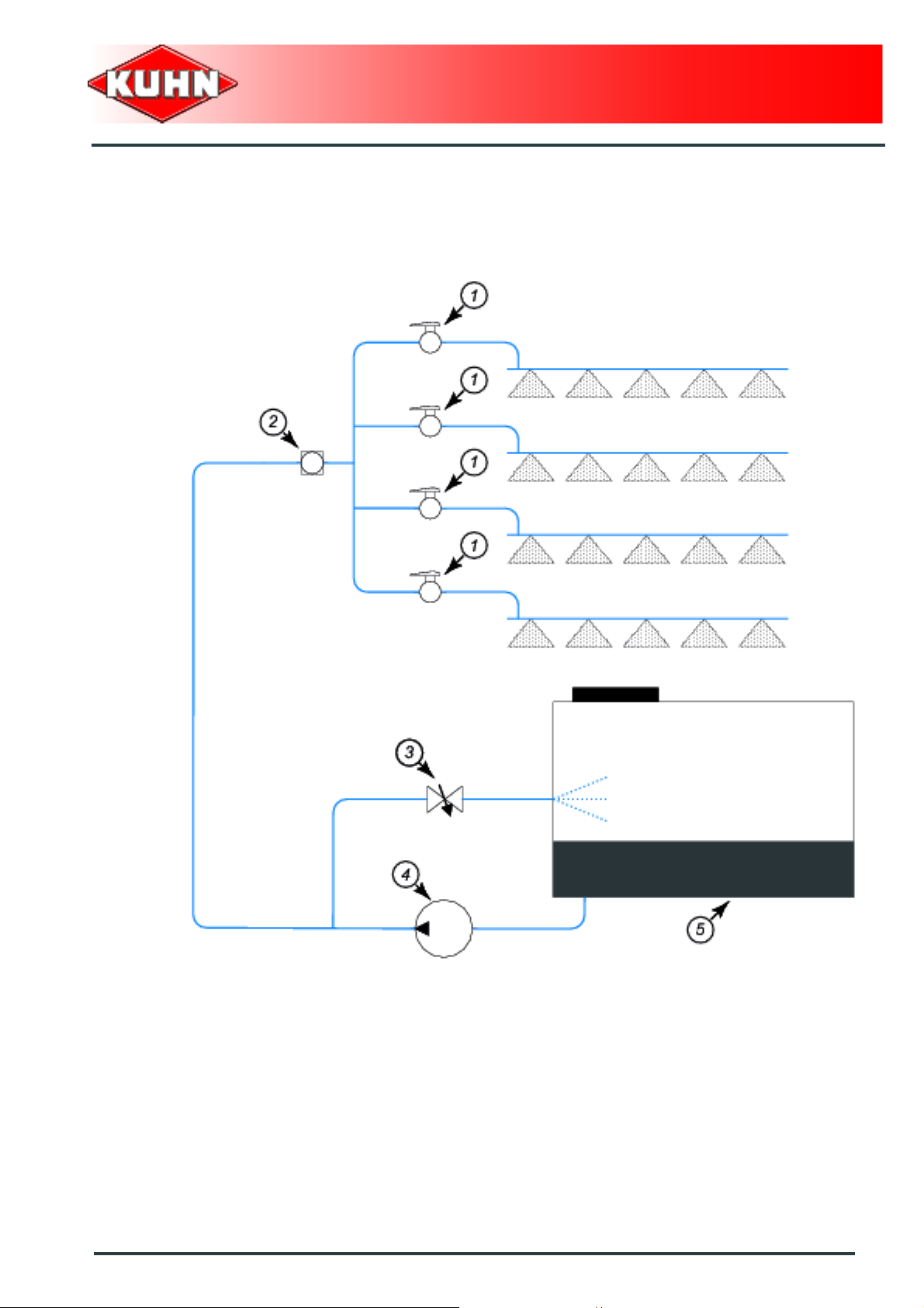
6. Circulation
The machine is factory supplied with the following
circulations:
2-way standard circulation (N2)
0
Mounted field sprayers
OMNIS
1 : Section valve 2 : Flowmeter
3 : Flow regulation valve 4 : Pump
5 : Main tank
Machine specifications
39
Page 42

3-way standard circulation (N3)
0
Mounted field sprayers
OMNIS
1 : Section valve 2 : Flowmeter
3 : Flow regulation valve 4 : Pump
5 : Main tank 6 : Calibrated return
40
Machine specifications
Page 43

2-way semi-continuous circulation (S2)
0
Mounted field sprayers
OMNIS
1 : Section valve 2 : Flowmeter
3 : Flow regulation valve 4 : Pump
5 : Main tank 6 : Flow limiting disc
7 : Upper foil
Machine specifications
41
Page 44

3-way semi-continuous circulation (S3)
0
Mounted field sprayers
OMNIS
1 : Section valve 2 : Flowmeter
3 : Flow regulation valve 4 : Pump
5 : Main tank 6 : Calibrated return
7 : Flow limiting disc 8 : Upper foil
42
Machine specifications
Page 45

7. Required equipment
All equipments listed below are not always
compatible between each other or with your
machine.
See machine corresponding to a specific
configuration.
Check with your authorized KUHN dealer th e
equipment compatibility with your machine.
PTO shaft
The machines are factory fitted with one of the following
PTO shafts:
Pto shaft S2 1 3/8’’ (6).
or
Pto shaft W200E 8 x 32 x 38.
Mounted field sprayers
OMNIS
S.eps.png
The machine is factory delivered with the following
equipment:
Steps.
or
Without step.
Description
The step (1) gives easy access to the main opening.
Machine specifications
43
Page 46

Regulation
The regulation enables spraying a co ns tan t do se .
The machine is factory supplied with one of the following
flow regulations:
DPM regulation (Directly proportional to motor):
The boom flow is proportional to the engine speed.
Main section valve and section shut off is manual:
Main section valve is manual. Section shut off is manual.
Manual main flow control valve.
or
Mounted field sprayers
OMNIS
Main section valve is electric and the section shut of f
is manual:
Main section valve is electric. Section shut off is manual.
Manual main flow control valve.
or
Main section valve and section shut off is electric:
Main section valve is electric. Section shut off is electric.
Manual main flow control valve.
or
44
Machine specifications
Page 47

DPME regulation (output proportional to engine speed):
The boom flow is proportional to the engine speed.
Section shut off is electric. Electric main flow control
valve. The control box enables the opening and shu tting
of main flow control valve and to adjust the spraying
pressure.
or
DPAE regulation (Ground speed related application rate control):
The boom flow is proportional to the ground speed.
Section shut off is electric. Electric main flow control
valve.
Mounted field sprayers
OMNIS
Control box RPB:
A pressure sensor and speed sensor send information to
the control box.
Control box RSB3/REB3:
A flowmeter and speed sensor send information to the
control box.
The control box opens/closes the flow regulation valve to
maintain the programmed application rate.
Machine specifications
45
Page 48

DPM regulation (Directly proportional to motor)
Main section valve and section shut off is manual
0
Mounted field sprayers
OMNIS
1 : Section valve (Manual) 2 : Main stop valve (Manual)
3 : Flow regulation valve (Manual) 4 : Pump
5 : Main tank
46
Machine specifications
Page 49
DPM regulation (Directly proportional to motor)
Main section valve is electric and the section shut off is manual
0
Mounted field sprayers
OMNIS
1 : Section valve (Manual) 2 : Main stop valve (Electric)
3 : Flow regulation valve (Manual) 4 : Pump
5 : Main tank
Machine specifications
47
Page 50

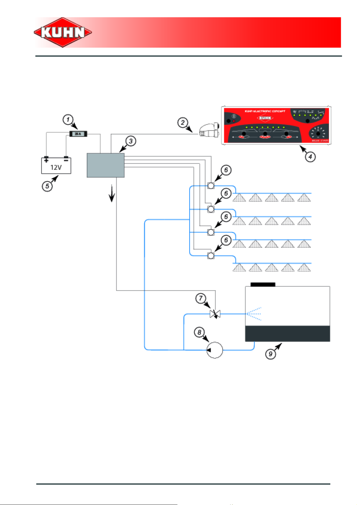
DPM regulation (Directly proportional to motor)
Main section valve and section shut off is electric
0
Mounted field sprayers
OMNIS
1 : Fuse 2 : CAN BUS wiring harness
3 : Junction box 4 : Control box
5 : Battery 6 : Section valve (Electric)
7 : Flow regulation valve (Manual) 8 : Pump
9 : Main tank
48
Machine specifications
Page 51
DPME regulation (output proportional to engine speed)
0
Mounted field sprayers
OMNIS
1 : Fuse 2 : CAN BUS wiring harness
3 : Junction box 4 : Control box
5 : Battery 6 : Section valve (Electric)
7 : Flow regulation valve (Electric) 8 : Pump
9 : Main tank
Machine specifications
49
Page 52

DPAE regulation (Ground speed related application rate control)
0
Mounted field sprayers
OMNIS
1 : Fuse 2 : CAN BUS wiring harness
3 : Junction box 4 : Control box
5 : Battery 6 : Section valve
7 : Flowmeter or Pressure sensor 8 : Flow regulation valve
9 : Speed sensor 10 : Wheel
11 : Pump 12 : Main tank
50
Machine specifications
Page 53

Control box
This machine is equipped with a control box to make all
adjustments.
The machine is factory delivered with the following
equipment:
Without control box: Main section valve and section shut
off is manual.
or
Control box AE (1): Main section valve is electric and the
section shut off is manual.
or
Mounted field sprayers
OMNIS
Control box DPS (2): DPM regulation. Main section valve
and section shut off is electric.
Manual main flow control valve.
or
Control box DPS (3): DPME Regulation (output
proportional to the engine speed).
or
Machine specifications
51
Page 54

Control box RPB (4): DPAE regulation (output
proportional to the groundspeed).
or
Mounted field sprayers
OMNIS
Control box RSB3/REB3 (5): DPAE regulation (output
proportional to the groundspeed).
The control box DPS / RPB / RSB3/REB3
functioning and setting are discribed in the
complementary instructions supplied.
52
Machine specifications
Page 55

Boom activators
The boom activators provide following hydraulic
functions:
- Boom height adjustment (1).
- Unfolding/folding of the boom arms (2).
- Slope corrector (3).
- Locking/unlocking of the boom central frame.
The machine is factory delivered with the following
equipment:
Manual boom:
Hand winch.
or
Hydraulic winch.
Mounted field sprayers
OMNIS
Hydraulic boom:
2-function electro-hydraulic selector.
or
3-function electro-hydraulic selector.
or
Solenoid valve block.
For models fitted with a solenoid valve block:
The machine is fitted with a CH10 control box
that groups the hydraulic functions.
The control box CH10 functioning and setting
are discribed in the complementary
instructions supplied.
Machine specifications
53
Page 56
Tank level
The machine is factory delivered with the following
equipment:
Floating gauge.
or
Floating gauge
and
Independent filling flowmeter:
This equipment enables informing the user on the
following points:
- Volume of liquid added in the tank.
- Instantaneous filling flow.
Mounted field sprayers
OMNIS
The functioning and settings of the control box
are described in the supplied complementary
manual.
Rinsing tank
The machine is factory delivered with the following
equipment:
Rinsing tank.
or
Without rinsing tank.
Description
The rinsing tank enables rinsing the main tank and the
spraying circuit by diluting the residual spray mixture.
54
Machine specifications
Page 57
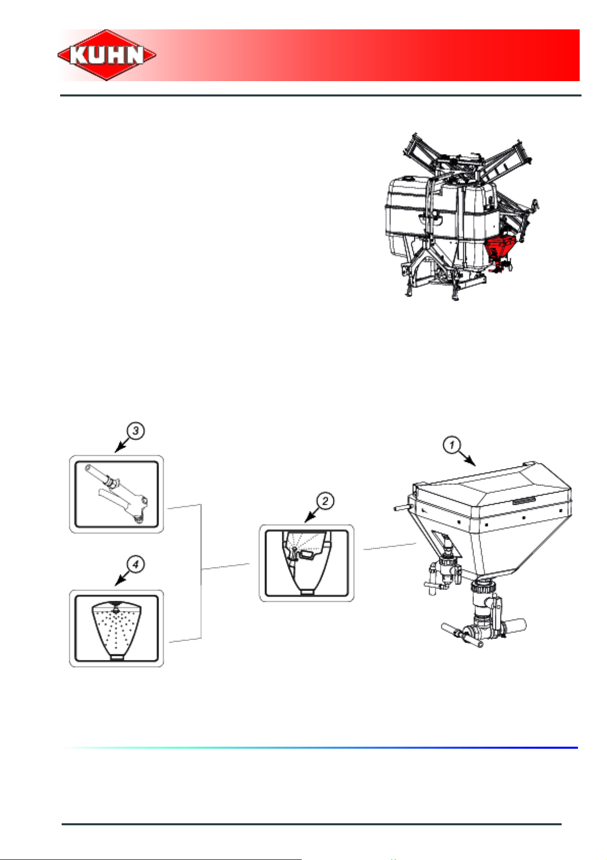
Incorporator
The machine is factory delivered with the following
equipment:
Incorporator.
or
Incorporator with spray lance.
or
Without product incorporator.
Description
The container rinse enables cleaning the container
inside.
The lance and the rinsing boom enables the inside of the
product incorporator to be rinsed.
0
Mounted field sprayers
OMNIS
1 : Incorporator 2 : Container rinser
3 : Spray gun (optional) 4 : Product incorporator rinsing boom
Machine specifications
55
Page 58

Mounted field sprayers
8. Sound levels
Sound levels have been measured in accordance with the measuring methods as defined in:
NF EN ISO 4254-1 «Agricultural machinery - Safety - Part 1: General requirements»
Weighted equivalent continuous acoustic pressure level at the driver's seat (closed cabin) L (A) eq:
Tractor only: 72 dB(A).
Tractor + machine: 75 dB(A).
OMNIS
56
Machine specifications
Page 59

$Putting into service
1. Description of control elements
The machine is fitted with the following components:
Main section valve and section shut off is manual.
or
Mounted field sprayers
OMNIS
Control box AE (1): Main section valve is electric and the
section shut off is manual.
or
Putting into service
57
Page 60

Control box DPS: DPM regulation. Main section valve
and section shut off is electric.
Manual main flow control valve.
or
Control box DPS: DPME Regulation (output proportional
to the engine speed).
or
Mounted field sprayers
OMNIS
Control box RPB: DPAE regulation (output proportional
to the groundspeed).
or
58
Putting into service
Page 61

Control box RSB3/REB3: DPAE regulation (output
proportional to the groundspeed).
For models fitted with a solenoid valve block:
- Control box CH10.
Mounted field sprayers
OMNIS
-Outlets.
Putting into service
59
Page 62

2. Description of the section valves
Main section valve and section shut off is
manual
0
Mounted field sprayers
OMNIS
1 : Main stop valve 2 : Section valve
Main stop valve:
Position a: Outlet opened.
Position b: Outlet closed.
Section valve:
Position a: Outlet opened.
Position b: Outlet closed.
60
Putting into service
Page 63

Main section valve is electric and the
section shut off is manual
0
Mounted field sprayers
OMNIS
1 : Main stop valve 2 : Section valve
Section valve:
Position a: Outlet opened.
Position b: Outlet closed.
Putting into service
61
Page 64

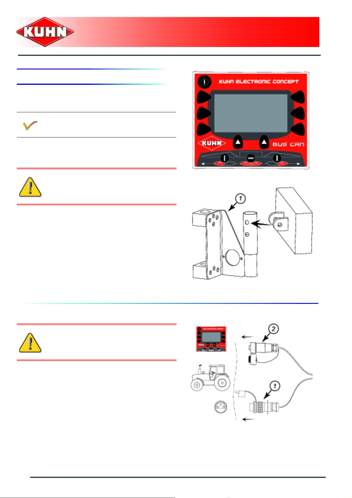
3. Description of the box AE
Positioning and parking
The control box must be easily accessible from
the tractor cab.
Control box mounting
The control box is placed in the tractor cab on a support
to be installed.
Control box removal
Disconnect and store control box in a dry and clean
place.
Mounted field sprayers
OMNIS
Description of the connection
Never connect battery charger or perform
welding tasks without having previously
disconnected the control box.
- Connect the machine 3-pin power plug (1).
- Connect wiring harness connector that connects the
machine to the control box.
For increased safety, it is recommended to use the
harness supplied with the machine..
Check that the connectors are in a good
condition and clean.
- Connect the wiring harness directly to the battery
terminals respecting the polarities.
62
Putting into service
Page 65

Description of the controls
0
Mounted field sprayers
OMNIS
1 : Opening / closing of the main shut-off valve
2 : Not used
Putting into service
63
Page 66

4. Description of the box DPS
This machine is equipped with a control box to make all
adjustments.
The control box DPS functioning and setting are
discribed in the complementary instructions
supplied.
Positioning and parking
The control box must be easily accessible from
the tractor cab.
Mounted field sprayers
OMNIS
Control box mounting
The control box is placed in the tractor cabin on support
(1) to mount.
Control box removal
Disconnect and store control box in a dry and clean
place.
Description of the connection
Never connect battery charger or perform
welding tasks without having previously
disconnected the control box.
- Connect the machine 3-pin power plug (1).
- Connect machine CAN BUS wiring harness connector
(2) to the control box.
64
Putting into service
Page 67

For increased safety, it is recommended to use the
harness supplied with the machine..
Check that the connectors are in a good
condition and clean.
- Connect the wiring harness directly to the battery
terminals respecting the polarities.
Description of the controls
0
Mounted field sprayers
OMNIS
1 : Start/Stop: Housing
2 : Selection key
3 : Switch: Left sequential opening/closing of the spraying sections
4 : Switch: Main opening/closing of the spraying sections
5 : Switch: Right sequential opening/closing of the spraying sections
6 : Switch: Pressure adjustment (
DPME Regulation (output proportional to the en gin e spee d ))
Putting into service
65
Page 68
5. Description of the box RPB
This machine is equipped with a control box to make all
adjustments.
The control box RPB functioning and setting are
discribed in the complementary instructions
supplied.
Positioning and parking
The control box must be easily accessible from
the tractor cab.
Mounted field sprayers
OMNIS
Control box mounting
The control box is placed in the tractor cabin on support
(1) to mount.
Control box removal
Disconnect and store control box in a dry and clean
place.
Description of the connection
Never connect battery charger or perform
welding tasks without having previously
disconnected the control box.
- Connect the machine 3-pin power plug (1).
- Connect machine CAN BUS wiring harness connector
(2) to the control box.
66
Putting into service
Page 69

For increased safety, it is recommended to use the
harness supplied with the machine..
Check that the connectors are in a good
condition and clean.
- Connect the wiring harness directly to the battery
terminals respecting the polarities.
Description of the controls
0
Mounted field sprayers
OMNIS
1 : Start/Stop: Housing
2 : Screen
3 : Selection key
4 : Switch: Left sequential opening/closing of the spraying sections
5 : Switch: Main opening/closing of the spraying sections
6 : Switch: Right sequential opening/closing of the spraying sections
Putting into service
67
Page 70

6. Description of the box RSB3/REB3
This machine is equipped with a control box to make all
adjustments.
The control box RSB3/REB3 functioning and
setting are discribed in the complementary
instructions supplied.
Positioning and parking
The control box must be easily accessible from
the tractor cab.
Mounted field sprayers
OMNIS
Control box mounting
The control box is placed in the tractor cabin on support
(1) to mount.
Control box removal
Disconnect and store control box in a dry and clean
place.
Description of the connection
Never connect battery charger or perform
welding tasks without having previously
disconnected the control box.
- Connect the machine 3-pin power plug (1).
- Connect machine CAN BUS wiring harness connector
(2) to the control box.
68
Putting into service
Page 71

For increased safety, it is recommended to use the
harness supplied with the machine..
Check that the connectors are in a good
condition and clean.
- Connect the wiring harness directly to the battery
terminals respecting the polarities.
Description of the controls
0
Mounted field sprayers
OMNIS
1 : Start/Stop: Housing
2 : Screen
3 : Selection key
4 : Start/Stop: Foam marker left
5 : Switch: Left sequential opening/closing of the spraying sections
6 : Switch: Main opening/closing of the spraying sections
7 : Switch: Right sequential opening/closing of the spraying sections
8 : Start/Stop: Foam marker right
Putting into service
69
Page 72

7. Description of the box CH10
For models fitted with a solenoid valve block:
The machine is fitted with a CH10 control box
that groups the hydraulic functions.
The control box CH10 functioning and setting
are discribed in the complementary
instructions supplied.
Positioning and parking
The control box must be easily accessible from
the tractor cab.
Mounted field sprayers
OMNIS
Control box mounting
The control box is placed in the tractor cabin on support
(1) to mount.
Control box removal
Disconnect and store control box in a dry and clean
place.
Description of the connection
Never connect battery charger or perform
welding tasks without having previously
disconnected the control box.
- Connect the electric wiring harness connector that
links the machine to the auxiliary control box CH10
(2).
- Connect the electric wiring harness connector that
links the auxiliary control box CH10 (2) to the main
control box RSB/REB3 (1).
70
Putting into service
Page 73

Description of the controls
0
Mounted field sprayers
OMNIS
1 : Start/Stop: Housing
2 : Switch: Unfolding/folding of the left outer arm
3 : Switch: Unfolding/folding of the central arms
4 : Switch: Unfolding/folding of the right outer arm
5 : Switch: Auxiliary hydraulic function
6 : Switch: Locking/unlocking of the boom central frame
7 : Switch: Positioning of the follower axle
8 : Switch: Automatic/manual guidance of the follower axle
9 : Switch: Raising/lowering of the left variable geometry
10 : Switch: Raising/lowering of the right variable geometry
11 : Switch: Raising/lowering of the boom
12 : Switch: Slope corrector
Putting into service
71
Page 74

8. Description of the valves
0
Mounted field sprayers
OMNIS
1 : Suction valve 2 : Rinsing tank valve (optional)
3 : Discharge valve 4 : Product incorporator lever (optional)
5 : Accessory valve 6 :
External suction 1 4 G E C
External suction + Incorporation (optional) 1 4 G D A
Incorporation (optional) 2 4 G D A
Spraying 24GEC
Rinsing of the incorporation circuit (optional) 1 3 G D A
Boom rinsing (optional) 1 3 G E C
Tank rinsing (optional) 1 3 F E C
Cleaning the machine on the outside (optional) 1 3 G E B
Filter cleaning 1 4 G E A
Outer discharge 2 4 G E B
72
Putting into service
Page 75

Suction valve:
The valve lever position indicates the origine of
the liquid sucked by the pump.
Position a: External suction.
Position b: Main tank suction.
Discharge valve:
The valve lever position indicates the destination
of the liquid that has flown back from the pump.
Position a: Outer discharge.
Position b: Booms.
Position c: Outlet closed.
Mounted field sprayers
OMNIS
Rinsing tank valve (optional):
The valve lever position indicates the origine of
the liquid sucked by the pump.
Position a: Rinsing tank suction.
Position b: Outlet closed.
Product incorporator lever (optional):
Position a: Outlet opened.
Position b: Outlet closed.
When optional equipment is used, follow
specific procedures mentioned in the related
section:
- Tank gyrocleaner.
Putting into service
73
Page 76

9. Coupling and uncoupling
Description of coupling elements
The machine is fitted with the following components:
- A PTO shaft.
- A 3-point hitch.
- 1 electric plug for the signalling equipment.
- 1 machine 12 V power plug.
- 1 CAN BUS connector linked to the control box.
For models fitted with a 2-function electrohydraulic selector:
and
For models fitted with a 3-function electro-
hydraulic selector:
Mounted field sprayers
OMNIS
The hydraulic hoses are fitted with a
push-pull coupling (ISO 7241
standard).
- 2 hydraulic hoses that pressurize the
hydraulic valve bank.
- 1 hydraulic hose that pressurizes the boom
height circuit.
For models fitted with a solenoid valve block:
The hydraulic hoses are fitted with a
push-pull coupling (ISO 7241
standard).
- 2 hydraulic hoses that pressurize the
hydraulic valve bank.
74
Putting into service
Page 77

Preparing the tractor
For driver safety, always use a tractor
equipped with a cab.
The machine adapts to tractors fitted with a 3 point
linkage category 2.
The tractor must be equipped with:
- A 7-pin electric plug for the electrical signalling
equipment.
- A 3-pin electric plug for the control box.
Mounted field sprayers
OMNIS
For models fitted with a 2-function electrohydraulic selector:
and
For models fitted with a 3-function electro-
hydraulic selector:
- 1 single acting hydraulic outlet.
- 1 double acting hydraulic outlet.
The single acting hydraulic valve
allows adjusting the boom height.
The double acting hydraulic valve
enables controlling the following
functions:
- Unfolding/folding of the boom arms.
- Slope corrector (optional).
Putting into service
75
Page 78

For models fitted with a solenoid valve block:
- 1 single acting outlet with free return to the
tank.
The machine is fitted with a CH10
control box that groups the hydraulic
functions. The control box CH10
functioning and setting are discribed in
the complementary instructions
supplied.
Make sure that the oil flow does not exceed
20 L/min (5.3 US gal/min).
Mounted field sprayers
OMNIS
The tractor pto must rotate at a maximum speed of
540 min
-1
.
The tractor must be fitted with lower link
stabilizers.
The front axle load (1) must never, under any
circumstances, be less than 20% of the
tractor's unladen weight.
76
Putting into service
Page 79

Hitch pin parallelism
- Adjust tractor lift rods so that lower linkage arms are
at equal height from ground.
Mounted field sprayers
OMNIS
For models fitted with DPAE regulati on (output
proportional to the groundspeed):
Speed sensor
The speed sensor detects the presence or not
of a metal mass (Lug stud, screw head etc.).
- Position speed sensor on the rigid part
(Example: Axle).
• The distance between between the
sensitive sensor side and the metal part
must be of approximately 4 mm (0.16’’).
• If necessary, position metallic studs on
the rim. The angular distribution of the
studs must be regular.
- Check that the orange diode comes on
each time a stud passes in front of the
sensor.
Putting into service
77
Page 80

Coupling the machine
Prior to coupling the machine, check that it
can move inadvertently and that the parking
stand is in the required position.
Couple the machine only with the tank empty.
Place the machine on level ground.
Make sure the spraying boom is folded.
Tighten tractor parking brake before placing
yourself between the tractor and the
machine.
In parking position:
Mounted field sprayers
OMNIS
- Slowly reverse the tractor in line with the machine until
being at 0.5 m (1’8’’) of the machine.
- Adjust the lift linkage height to have the hitch points in
line.
- Disengage the tractor PTO and switch off the engine.
- Apply the tractor parking brake.
78
Putting into service
Page 81

Electrical connections
- Connect the electric signalling plug.
- After making the connections, check that there is no
risk of the cables being caught during operation.
Hydraulic connections
Before connecting hoses to the tractor
hydraulics, ensure that trac tor and machine
circuits are not under pressure.
Mounted field sprayers
OMNIS
For models fitted with a 2-function electrohydraulic selector:
and
For models fitted with a 3-function electro-
hydraulic selector:
- Connect the hydraulic hose fitted with a
shut-off valve to the tractor single acting
spool valve.
- Connect hydraulic hoses to the tractor
double acting spool valve.
For models fitted with a solenoid valve block:
- Connect the hydraulic hose with black mark
to the tractor pressure intake.
- Connect the hydraulic hose to the tractor
free return.
Putting into service
79
Page 82
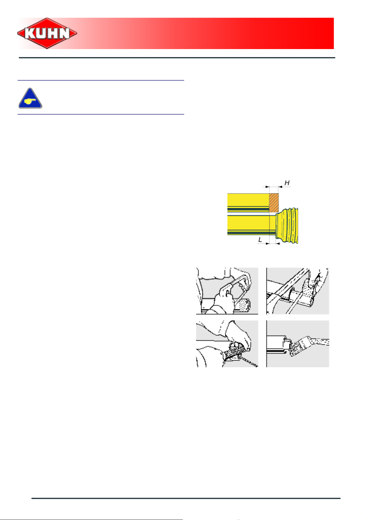
Primary PTO shaft
Make sure that the PTO shaft is correctly
adjusted, to avoid premature wear and tear.
Mounted field sprayers
OMNIS
The tractor pto must rotate at a maximum speed of
540 min
-1
.
- Separate the two half PTO shafts and connect them to
the machine's input shaft and to the tractor PTO stub.
- Check the length of the PTO shaft:
• When the PTO shaft is in its maximum overlap
position (retracted), tubes should not butt against
the yokes. As a s afety measure, a clearance (L) of
at least 25 mm (1’’) must be maintained.
• When at maximum length, the tube overlap must no t
be below a third of its length.
If this is not the case:
- Mark length (H) to cut when the transmission is the
maximum overlap position.
- Shorten the guard tubes and the transmission tubes
by the same length.
- Bevel and clean the tubes.
- Grease the inside of the outer tube.
80
Putting into service
Page 83

Never operate the PTO shaft at an angle X exceeding
30°.
Mounted field sprayers
OMNIS
To avoid serious accidents, the PTO drive
shaft guards must be properly in place and
fixed with the chains provided.
- Attach PTO shaft guard using chain provided in order
to prevent it from rotating.
Immediately replace any worn or damaged
guard.
Putting into service
81
Page 84

3-point attachment
- Slowly reverse the tractor until the lower link ball joints
are in line with the lower hitch pins.
- Unlock and remove the lynch pin of each hitch pin.
- Couple the lower link ball joints to the lower hitch pins.
- Secure each lower link with lynch pin.
- Unlock and remove the lynch pin of the hitch pin.
- Remove the upper hitch pin.
- Position the top link inside the upper coupling yoke.
- Insert the upper hitch pin inside the upper coupling
yoke hole.
- Secure hitch pin with lynch pin.
Mounted field sprayers
OMNIS
- Adjust the top link length so that the machine is
horizontal with regards to the ground.
- Raise machine using tractor lift.
When optional equipment is used, follow
specific procedures mentioned in the related
section:
- Automatic hitch.
82
Putting into service
Page 85
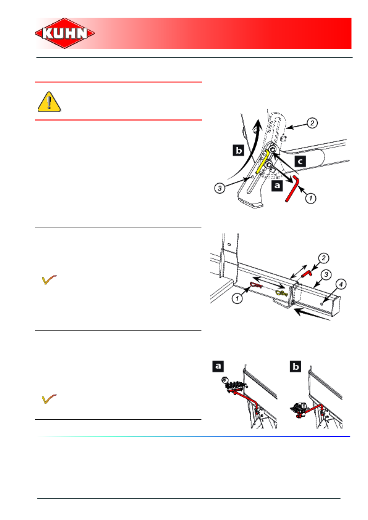
Parking stands
The parking stands must be adjusted in the
same position.
Front parking stands:
- Remove the parking stand lock pin (1).
- Reinstall parking stand (2).
- Insert pin in hole corresponding to transport position
(3).
- Repeat procedures on the other parking stand.
Mounted field sprayers
OMNIS
For models equipped with boom RVA / RHX:
Rear parking stands:
- Remove pin (1).
- Remove the parking stand lock pin (2).
- Reinstall parking stand (3).
- Insert pin in hole corresponding to transport
position (4).
- Refit pin (1).
Repeat procedures on the other parking
stand.
For models fitted with DPM regulation:
- Place the section valve holder in work
position.
• Position a: Parking position.
• Position b: Working position.
Putting into service
83
Page 86

Adjusting the machine
Lateral adjustment of the lower linkage arms
- Balance the play on either sides of the lift linkage and
lock lower link stabilizers.
Mounted field sprayers
OMNIS
Adjusting the machine's horizontality
- Adjust the top link length so that the machine is
horizontal with regards to the ground.
84
Putting into service
Page 87
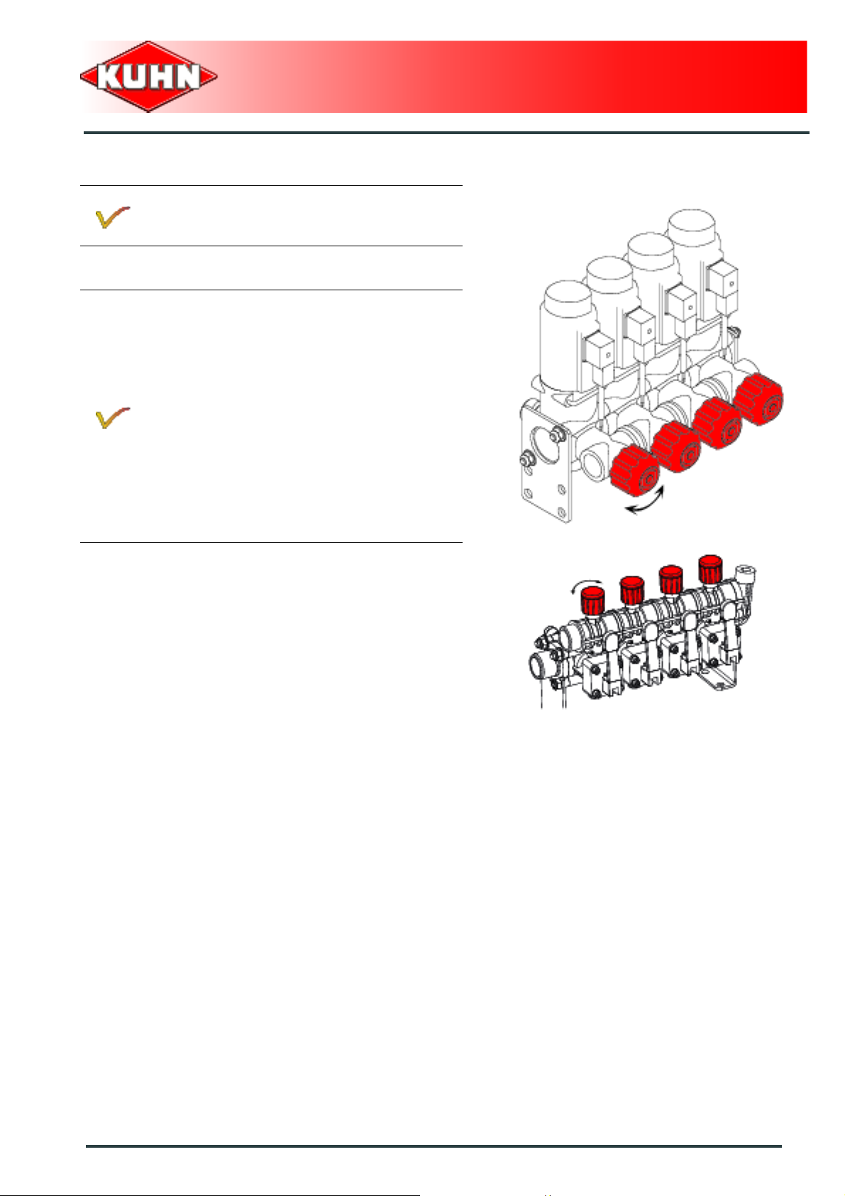
Adjustment of the calibrated returns
Adjustment to make before each nuse with a
new nozzle colour.
For models fitted with a standard 2-way or 2-way
semi-continuous circulation:
- Fully tighten the calibrated returns.
Mounted field sprayers
OMNIS
Putting into service
85
Page 88
For models fitted with a standard 3-way or 3-way
semi-continuous circulation:
- Fill the main tank to half its capacity with
clean water.
- Place valves in spraying position.
- Engage the tractor PTO. PTO speed:
540 min
- Open all sections.
- Adjust pressure to 2 bar (29 psi).
Adjust section linked to the pressure gauge at
the end. The adjustment value equals a section
value with the same number of nozzles.
- Shuting off a section.
- Turn shut-off section valve knob until
reaching 2 bar (29 psi).
- Open the section.
- Repeat procedure for each section.
-1
.
Mounted field sprayers
OMNIS
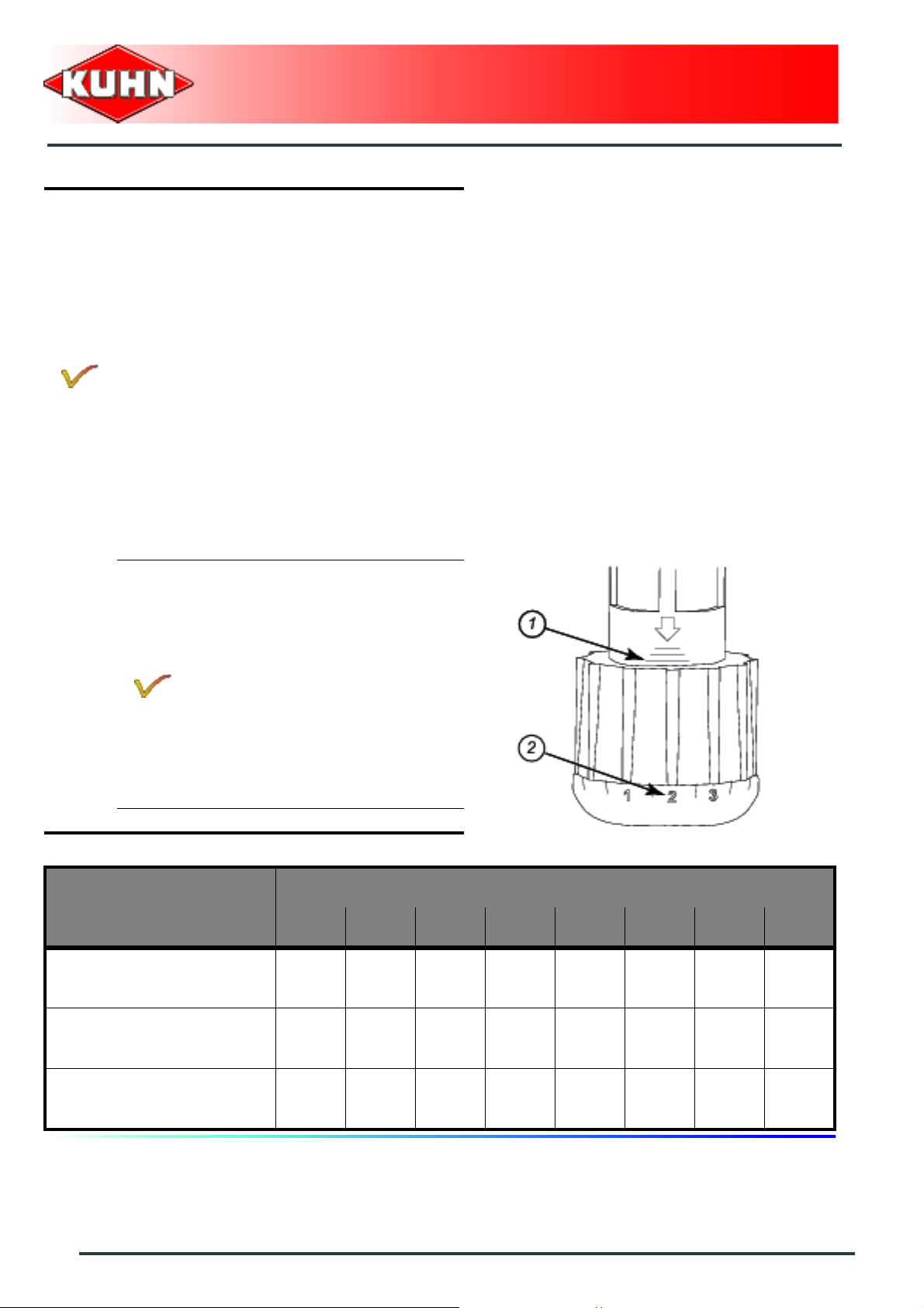
For models fitted with DPME
regulation (output proportional to the
engine speed):
and
For models fitted with DPAE
regulation (output proportional to the
groundspeed):
- Not e th e s ec tio n valv e kn ob sett ing :
• Number of lines visible on the
valve body (1).
• Digit on the knob (2).
• Example: 3 2
Nozzles Sections
Color 1 2 3 4 5 6 7 8
86
Putting into service
Page 89

Uncoupling the machine
Park the machine on an even fairly level ground.
Only unhitch the machine when the tank is
empty.
Make sure the spraying boom is folded.
Tighten tractor parking brake before placing
yourself between the tractor and the machine.
From the transport position:
- Disengage the tractor PTO and switch off the engine.
- Apply the tractor parking brake.
For models fitted with DPM regulation:
- Position section valve holder in parking
position.
• Position a: Parking position.
• Position b: Working position.
Mounted field sprayers
OMNIS
Parking stands
The parking stands must be adjusted in the
same position.
Front parking stands:
- Remove the parking stand lock pin (1).
- Lower parking stand (2).
- Insert pin in one of the 3 parking stand upper holes
corresponding to parking position (3).
- Repeat procedures on the other parking stand.
Putting into service
87
Page 90

For models equipped with boom RVA / RHX:
Rear parking stands:
- Remove pin (1).
- Remove the parking stand lock pin (2).
- Lower parking stand (3).
- Insert pin in the hole corresponding to the
parking position (4).
- Refit pin (1).
Repeat procedures on the other parking
stand.
- Lower the tractor three-point linkage to rest the
machine on the ground.
- Check the machine stability.
Mounted field sprayers
OMNIS
Hydraulic and electric connections
Before disconnecting a hose, depressurize
the hydraulic circuit.
- Disconnect and store control box in a dry and clean
place.
- Depressurise the hydraulic circuit.
- Disconnect hydraulic hoses and electric plug.
88
Putting into service
Page 91

Primary PTO shaft
- Disconnect the PTO shaft from the tractor.
- Secure PTO shaft into its' support (1).
3-point attachment
- Unlock and remove the lynch pin of the hitch pin.
- Remove the upper hitch pin.
- Detach the top link from the machine end.
- Insert the upper hitch pin inside the upper coupling
yoke hole.
- Secure hitch pin with lynch pin.
Mounted field sprayers
OMNIS
Putting into service
89
Page 92

- Unlock and remove the lynch pin of each hitch pin.
- Uncouple lower linkage arms.
- Secure each lower link with lynch pin.
- Lower the tractor three-point linkage.
- Move forward with the tractor
Mounted field sprayers
OMNIS
The machine is uncoupled.
When optional equipment is used, follow
specific procedures mentioned in the related
section:
- Automatic hitch.
90
Putting into service
Page 93

$Instructions for transport
Before placing the machine into transport
position:
- Check that nobody is within the machine
pivoting area. If there is someone, make
sure the person moves away.
- Place the machine on level ground.
1. Putting the machine into transport position
Mounted field sprayers
OMNIS
Prior to handling the booms, check that
overhead power lines are at a safe distance.
When unfolding/folding the boom arms,
check that there is no risk of hoses getting
caught.
Boom RPL
From the working position:
- Fully lower the booms.
- Lock the central boom frame.
Instructions for transport
91
Page 94

- Fold the outer arms.
- Fold the left central arm.
- Fold the right central arm.
- Lock the right boom:
• Reinstall plate (2).
• Refit pin (1).
Mounted field sprayers
OMNIS
The machine is in transport position.
92
Instructions for transport
Page 95

Boom RJP2
From the working position:
- Fully lower the booms.
- Lock the central boom frame.
For models fitted with a 2 arm boom:
- Fold the outer arms.
Mounted field sprayers
OMNIS
For models fitted with a 3 arm boom:
- Unlock the third arm.
- Fold the third arm.
- Lock the third arm.
- Proceed the same way on the other side.
- Fold the second arms.
- Unlock the left boom.
- Fold the left central arm.
Instructions for transport
93
Page 96

- Lock the left boom.
Mounted field sprayers
OMNIS
- Unlock the right boom.
- Fold the right central arm.
- Lock the right boom.
The machine is in transport position.
94
Instructions for transport
Page 97

Boom RHX
From the working position:
- Fully lower the booms.
- Fold the outer arms.
- Fold the central arms.
For models fitted with a 2-function electrohydraulic selector:
and
For models fitted with a 3-function electro-
hydraulic selector:
The machine is fitted with a DPS / RPB /
RSB3/REB3 control box that groups the
hydraulic functions.
Mounted field sprayers
OMNIS
For models fitted with a solenoid valve block:
The machine is fitted with a CH10 control box
that groups the hydraulic functions.
The machine is in transport position.
Instructions for transport
95
Page 98

Boom RVA
From the working position:
- Fully lower the booms.
- Fold the outer arms.
- Fold the central arms.
For models fitted with a 2-function electrohydraulic selector:
and
For models fitted with a 3-function electro-
hydraulic selector:
The machine is fitted with a DPS / RPB /
RSB3/REB3 control box that groups the
hydraulic functions.
Mounted field sprayers
OMNIS
For models fitted with a solenoid valve block:
The machine is fitted with a CH10 control box
that groups the hydraulic functions.
The machine is in transport position.
96
Instructions for transport
Page 99

2. Conformity with the road regulations
Before driving the machine on public roads,
ensure that the machine complies with
current highway code regulations.
Always keep to the legal speed limit for
driving the machine assembly on public
roads.
During transport, adapt the travel speed to
suit the road conditions.
When the main tank is full, reduce travel
speed to limit rolling movement in the tank
Mounted field sprayers
OMNIS
- Check that the retroreflective signalling equipment is
clean and that the lighting equipment functio ns before
going on public roads.
- Immediately replace any worn or damaged signalling
panels or lights.
When optional equipment is used, follow
specific procedures mentioned in the related
section:
- Flashing light.
Instructions for transport
97
Page 100

$Instructions for work
Before placing the machine in working
position:
- Check that nobody is within the machine
pivoting area. If there is someone, make
sure the person moves away.
- Place the machine on level ground.
1. Putting the machine into work position
Mounted field sprayers
OMNIS
Prior to handling the booms, check that
overhead power lines are at a safe distance.
When unfolding/folding the boom arms,
check that there is no risk of hoses getting
caught.
Boom RPL
From the transport position:
- Unlock the right boom:
• Remove pin (1).
• Remove plate (2).
98
Instructions for work
 Loading...