

Page 1

OPERATOR'S MANUAL
KN093CGB C
Merger
Merge Maxx 900
KN093CGB C
- English - 04-2010
Page 2

Page 3

Merger
Merge Maxx 900
$Dear Owner
In buying a Kuhn machine you have chosen wisely. Into it have gone years of thought, research and
improvement. You will find, as have thousands of owners all over the world, that you have the best that
engineering skill and actual field testing can produce. You have purchased a dependable machine, but only
through proper care and operation can you expect to receive the performance and long service built into it.
This manual contains all the necessary information for you to receive full efficiency from your machine. The
performance you get from this machine is largely dependent on how well you read and understand th is manual
and apply this knowledge. Please DO NOT ASSUME YOU KNOW HOW TO OPERATE AND MAINTAIN YOUR
MACHINE before reading this manual carefully. KEEP THIS MANUAL AVAILABLE FOR REFERENCE. Pass
it on to the next owner if you re-sell the machine.
Your KUHN dealer can offer a complete line of genuine KUHN service parts. These parts ar e manufactured and
carefully inspected in the same factory that builds the machine to assure high quality and accurate fitting of any
necessary replacements.
About improvements
We are continually striving to improve our products. It therefore reserves the right to make improvements or
changes when it becomes practical to do so, without incurring any obligations to make changes or additions to
the equipment sold previously.
Designated use of the machine
The MERGE MAXX 900 must only be used for the work for which it has been designed:
- Raking of previously cut green or wilted forage.
Document illustrations
The illustrations in this manual may be based on one typ e of machine only. However, all instructions apply to all
machines covered in this manual.
Dear Owner
1
Page 4

Merger
Merge Maxx 900
$Contents
Dear Owner.....................................................................................................................1
Contents .........................................................................................................................2
Identification of the machine.........................................................................................4
Front view (working position) .........................................................................................................4
Rear view (working position)...........................................................................................................4
Model identification plate ................................................................................................................5
Optional equipment..........................................................................................................................5
Safety...............................................................................................................................6
Description of symbols used in this document.............................................................................6
Safety instructions...........................................................................................................................7
Location and description of safety decals on the machine .......................................................19
Road safety equipment and recommendations...........................................................................22
Machine specifications................................................................................................25
Description and glossary...............................................................................................................25
Technical specifications............. ... ... ... .... ... ... ... ... .... ............................................. ... ... .... ... ............26
Sound levels ......... ... ... .... ... ... ... .... ............................................. ......................................................28
Required equipment.......................................................................................................................27
Putting into service......................................................................................................29
Description of control elements....................................................................................................29
Coupling and uncoupling..............................................................................................................35
Instructions for transport............................................................................................46
Putting the machine into transport position................................................................................46
Conformity with the road regulations...........................................................................................49
2
Contents
Page 5

Merger
Merge Maxx 900
Instructions for work...................................................................................................50
Putting the machine into work position............. ..........................................................................50
Adjustments in working position..................................................................................................53
Machine use....................................................................................................................................66
Optional equipment.....................................................................................................78
Wide wheels ... ... .... ... ... ... .... ... .......................................... ... ... .... ... ... ... ... ..........................................78
Maintenance and storage............................................................................................ 79
Frequency chart .............................................................................................................................79
Lubrication............................................................................................ ..........................................81
Maintenance....................................................................................................................................89
Storage............................................................................................................................................96
Trouble shooting guide...............................................................................................97
Appendix ....................................................................................................................101
Limited warranty........................................................................................................ 107
Contents
3
Page 6
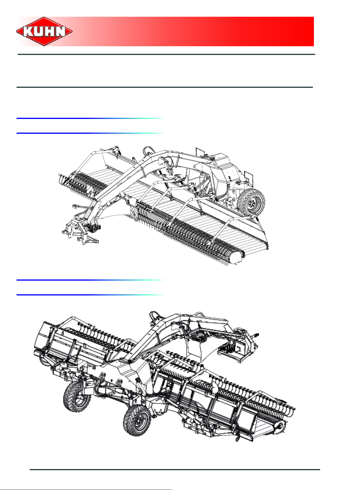
$Identification of the machine
1. Front view (working position)
Merger
Merge Maxx 900
2. Rear view (working position)
4
Identification of the machine
Page 7
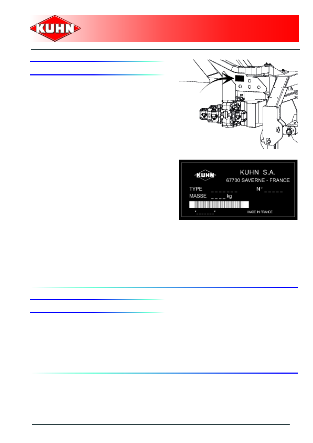
3. Model identification plate
Please write below the type and serial number of the
machine. This information is to be indicated to the dealer
for all spare parts orders.
Merger
Merge Maxx 900
Type: MERGE MAXX 900
Serial no.:
4. Optional equipment
Tick box corresponding to the equipment fitted on your
machine:
Kit no. 1146870: Wide wheels (500/45-22.5 14 ply).
Part no. 1409957: Suction-grip holder..
Identification of the machine
5
Page 8
$Safety
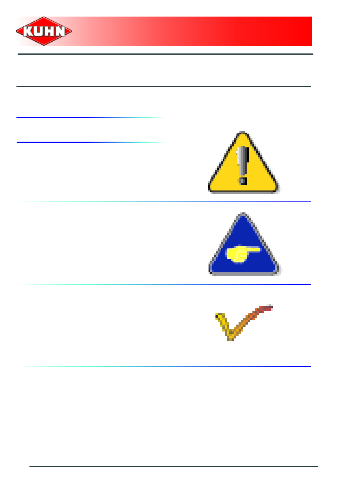
1. Description of symbols used in this document
This symbol indicates a potentially hazardous situation
that if not avoided, could result in serious bodily injury.
Merger
Merge Maxx 900
This symbol is used to identify special instructions or
procedures which, if not followed strictly, could result in
machinery damage.
This symbol is used to communicate technical
information of particular interest.
6
Safety
Page 9

Merger
Merge Maxx 900
2. Safety instructions
Introduction
The machine must only be operated, maintained and repaired by competent persons who are familiar with
machines' specifications and operation and aware of safety regulations fo r preventing accidents.
The operator must imperatively respect safety instructions in this manual and in the warnings posted on the
machine. The operator is also obliged to respect current le gislation concerning accident prevention, wo rk safety
and public traffic circulation.
Designated use of the machine also means following operation, maintenance and repair recommendations
given by the manufacturer, and using only genuine spare parts, equipment a nd acce sso ries, as r ecom mended
by the manufacturer.
The manufacturer is not held liable for any damage resulting from machine applications other than those
specified by the manufacturer. Any use other than the designated operation is at the risk and responsibility of
the operator.
The manufacturer is not held liable for any damage or accident re sulting from machine modifications carried out
by the operator himself or by a third party without previous written agreement from the manufacturer.
Read and follow the safety instructions
Before using the machine, carefully read all the safety
instructions in this manual and the warnings placed on
the machine.
Before starting work, the operator must be familiar with
all machine controls, handling devices and their
functions. It is too late to learn once work has been
started!
Never let anyone operate the machine who is not traine d
to do so.
Should you have any difficulties in understanding certain
parts in this manual, please contact your KUHN dealer.
Precautions to be taken before carrying out
any operations on the machine
Before leaving the tractor or before adjusting,
maintaining or repairing the machine, disengage the
PTO drive, turn off the engine, remove ignition key and
wait until all moving parts have come to a complete stop
and apply park brake.
Safety
7
Page 10
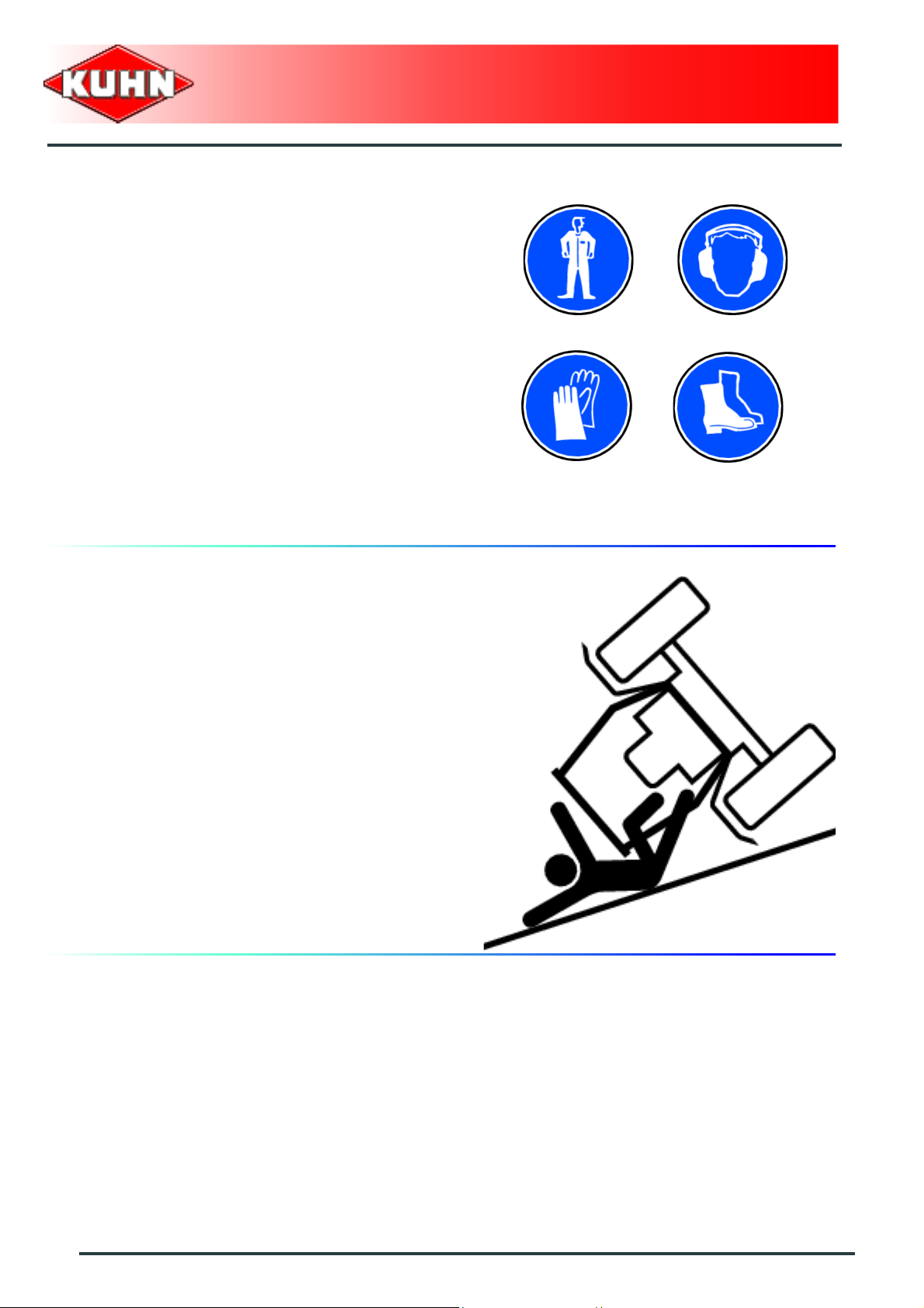
Precautions to take before using the
machine
Do not wear loose clothing which could become caught
up in moving parts.
Wear the appropriate protective clothing for the work in
hand (gloves, shoes, goggles, helmet, ear defenders,
etc.).
Ensure that all operating controls (ropes, cables, rods,
etc) are placed so as they cannot be operated
unintentionally and cause damage or injury.
Before operating the machine, check tightness of nuts
and bolts, particularly on fixing elements (tines, forks,
blades, knives, etc). Retighten if necessary.
Before operating the machine, ensure that all the safety
guards are firmly in place and in good condition.
Immediately replace any worn or damaged guard.
Merger
Merge Maxx 900
Precautions when driving
Tractor handling, stability, performance and braking
efficiency are all affected by weight distribution, trailed or
mounted implements, additional ballast and driving
conditions. It is therefore of great importance that the
operator exercises caution in every given situation.
Groundspeed must be adapted to ground conditions as
well as to roads and paths. Always avoid abrupt change s
of direction.
Be particularly cautious when turning corners, paying
attention to machine overhang, length, height and
weight.
Never use a narrow track tractor on very uneven or
steeply sloping ground.
Never leave the tractor seat while the machine is
operating.
Carrying people or animals on the machine when
working or in transport is strictly forbidden.
8
Safety
Page 11
Precautions when driving on public roads
Dimensions
Depending on the dimensions of the machine, contact
the relevant authorities to ensure that it can be legally
transported on public roads.
If the machine is over the maximum legal size, follow the
local regulations for special transportation of oversize
equipment.
Transport position
Before transporting the machine on public roads, place
the machine into its transport position, according to the
instructions in this manual.
Lights and indicators
Before transporting the machine on public road s, ensure
that all legally required lightings and signallings are in
place.
Ensure that lightings and signallings are clean and in
good working order. Replace any missing or broken
equipment.
Merger
Merge Maxx 900
Always obey current regulations for driving
on roads.
Gross weight and weight per axle
The drawings are not legally binding, their only aim is to illustrate the method to use.
Prior to driving on public roads, check t hat criteria are met t o be in conformity with the count rie's
regulations:
- When coupling a tool to the front and rear 3-point lift linkage, the maximum authorized
payload must not be exceeded.
- When coupling tools to the front and rear 3-point lift linkages, the maximum load on each
axle's tires must not be exceeded.
- The load on the tractor front axle must al ways represe nt 20 % of the tractor unla den weight.
Safety
9
Page 12
For machines with hoppers or tanks:
- If the total unit weight exceeds the tractor Gross Combined Weight Rating in accordance
with the countrie's legislation, empty the hopper to travel on public roads.
- In any case, we recommend to travel on public roads with empty hoppers and tanks.
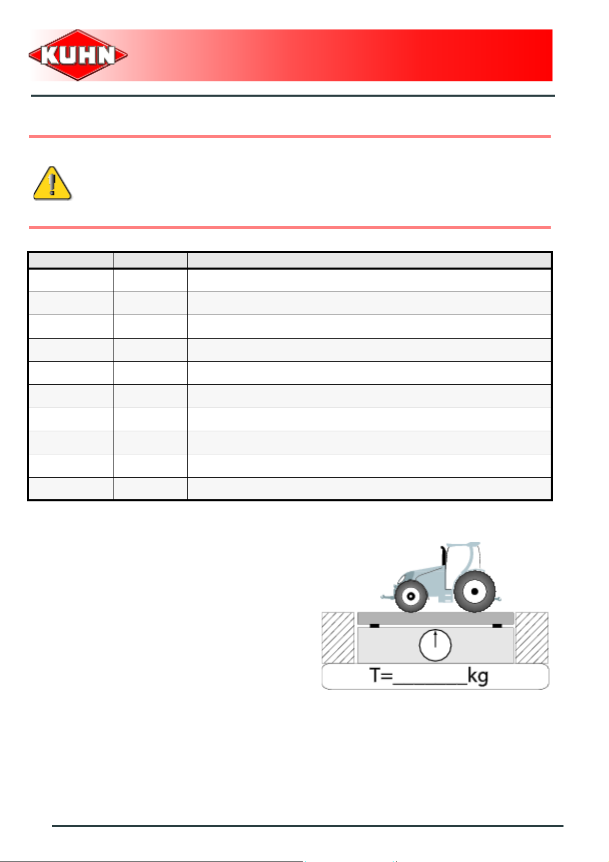
Description of symbols
Description Units Description
T kg Tractor unladen weight
PTAC kg Gross Combined Weight Rating
T1 kg Unladen load on tractor front axle
T2 kg Empty load on tractor rear axle
Merger
Merge Maxx 900
t kg Axle loads (Tractor + machine)
t1 kg Load on front axle (Tractor + machine)
t2 kg Load on rear axle (Tractor + machine)
t1 max kg Maximum load authorized on the tractor front axle according to the tires
t2 max kg Maximum load authorized on the tractor rear axle according to the tires
M1 kg Total weight of front tool or front ballast
Stage 1:
To measure:
- Tractor tare (T).
10
Safety
Page 13
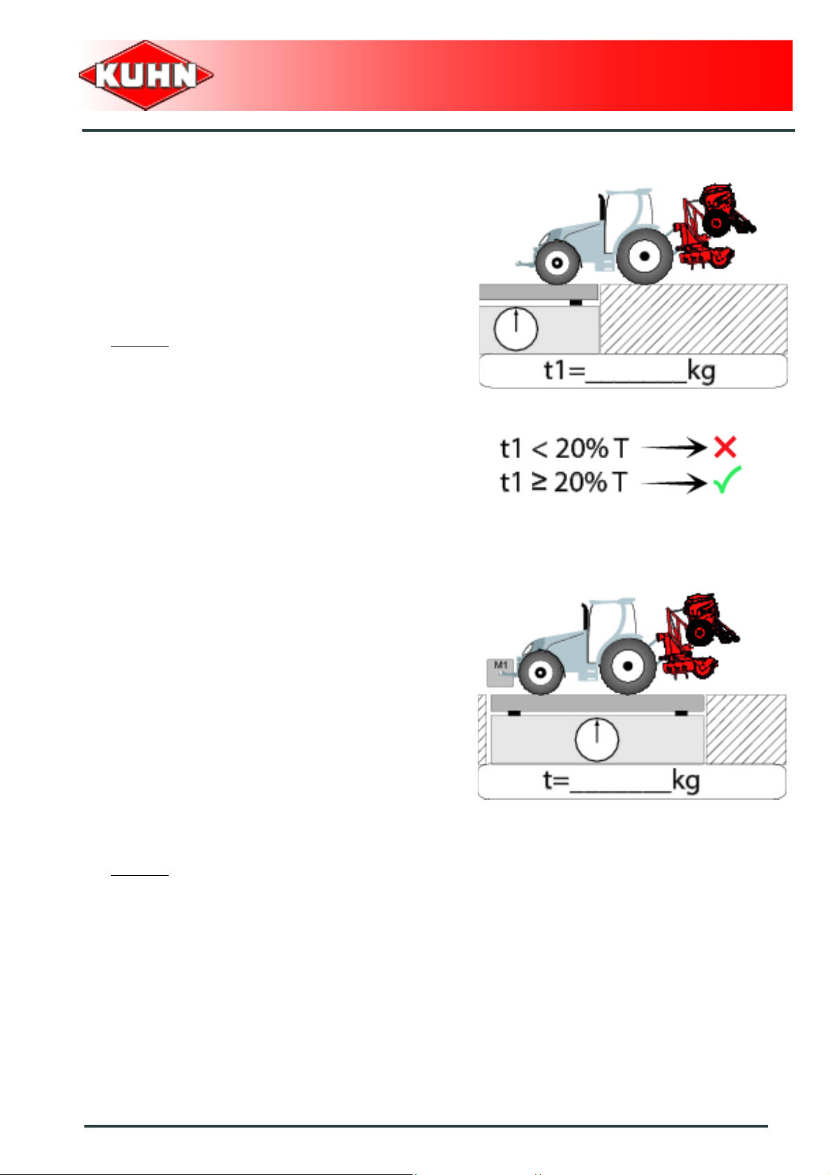
Stage 2:
- Couple the machine to the tractor.
To measure:
- Load on front axle (t1):
• Tractor + machine (transport position).
To do:
- If the front axle load (t1) is below 20% of the tractor
tare (T), add ballast weights (M1) to exceed the
minimum load on the front axle.
Example:
• (T) = 7500 kg (16535 lb)
• The front axle load must be of minimum 1500 kg
(3300 lb).(20% of T)
• (t1) = 700 kg (1545 lb).
• 700 kg (1545 lb) < 1500 kg (3300 lb).
• Add ballast weights until the minimum front axle
load is exceeded.
• Repeat checking procedure.
Merger
Merge Maxx 900
Stage 3:
To measure:
- Total weight (t):
• Tractor + machine (transport position).
• Ballast weights.
Checking:
- To go to the next stage:
• Check in the tractor's operator's manual that the
value measured is below the tractor's Gross
Combined Weight Rating.
To do:
- If t < PTAC go to the next stage.
- If the total unit weight exceeds the tractor Gross
Combined Weight Rating in accordance with the
countrie's legislation, empty the hopper to travel on
public roads.
Example:
• (t) = 10000 kg (24250 lb)
• PTAC = 13000 kg .
• t < PTAC : Go to the next stage.
Safety
11
Page 14
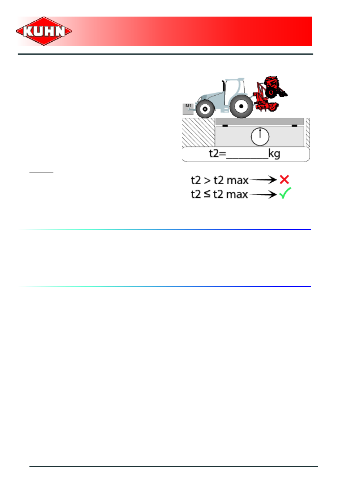
Stage 4:
To measure:
- Load on rear axle (t2):
• Tractor + machine (transport position).
• Ballast weights.
Checking:
- Check in the tractor's operator's manual that the value
measured is below the maximum allowed tractor rear
axle load.
- Check that tyre and rim specifiations are in conformity
with the requirements of the tractor manufacturer.
Example:
• Load on rear axle (t2) = 8500 kg (18740 lb)
• Check in the tractor's operator's manual that the
value measured is below the maximum allowed
tractor rear axle load.
• Check that tyre and rim specifiations are in
conformity with the requirements of the tractor
manufacturer.
Merger
Merge Maxx 900
Maximum speed
Always keep to the legal speed limit for driving a tractormachine assembly on public roads.
12
Safety
Page 15
Precautions when coupling
Before attaching the machine, make sure that it cannot
accidentally start moving (chock the wheels) and that the
parking stand is in the right position.
The machine must only be attached to the hitch points
provided for this purpose.
Never stand between the tractor and the machine when
operating the three point linkage.
Do not stand between the tractor and the machine
without ensuring that the parking brake is applied.
Hydraulic circuit
Caution! The hydraulic circuit is under high pressure.
Maximum pressure at work: 200 bar.
Before connecting hoses to the tractor hydraulics,
ensure that tractor and machine circuits are not under
pressure. Before disconnecting a hose, depressurize the
hydraulic circuit.
To avoid making incorrect connectio ns, mark hydraulic
couplers and corresponding hoses with colors.
WARNING! Functions could be reversed (for example:
lift/lower) and cause accidents.
Regularly check the hydraulic hoses. In case of normal
wear, replace the hydraulic hoses every 5 years.
Damaged or worn hoses must immediately be r eplaced.
When replacing the hydraulic hoses, only use hoses with
the specification recommended by the manufacturer of
the machine.
To locate a leak, use appropriate means. Protect body
and hands from liquid under pressure.
Any liquid under pressure (particularly oil from
hydraulics) can penetrate the skin and cause severe
injury. If injured, see a doctor immediately, there could
be danger of infection.
Before any adjustments, maintenance or repairs are
carried out, lower the machine to the ground,
depressurize the hydraulics, turn off the engine, remove
ignition key and wait until all moving parts have come to
a complete stop.
Merger
Merge Maxx 900
Safety
13
Page 16
PTO shaft
Use only PTO shafts supplied with the machine or
recommended by the manufacturer.
The protective shield of the tractor PTO stub, the PTO
shaft guards and the protective covering of the machine
input shaft must always be in place and in good
condition.
Make sure that the PTO shaft guards are secured with
the safety chains provided.
Any worn or damaged guards must be replaced
immediately. A worn guard or an unpro tecte d PTO shaft
can cause a serious or even a lethal accident.
Do not wear loose clothing that could be caught in the
rotating PTO shaft.
Before attaching or removing a PTO shaft, or before
doing any work on the machine, disengage the PTO
drive, turn off the engine, remove ignition key and wait
for all moving parts have come to a complete stop.
If the primary PTO shaft is equipped with a slip clutch or
a free wheel, these must be fitted on the machine side.
Ensure that the PTO shaft is always correctly fitted and
locked into place.
Before connecting the PTO shaft, ensure that the PTO
speed (rotational frequency) and directions of rotation
are in line with manufacturer's recommendat ion s.
Before engaging the PTO drive, make sure all people
and animals are clear from the machine. Never engage
the PTO drive when the tractor engine is stopped.
When uncoupling the machine, rest the PTO shaft on the
support specially provided, and replace protective cover
on the PTO stub of the tractor.
Read and follow the instructions in the operator's manual
provided with the PTO shaft.
Merger
Merge Maxx 900
14
Safety
Page 17
Precautions during manoeuvres
When moving the machine from the transport position to
the working position and vice versa, make sure that
nobody is within the machine pivoting area.
Remote controlled components
Danger of crushing and shearing can exist when
components are operated by hydraulic or pneumatic
controls. Keep away from these danger zones.
Tyres
Regularly check the tyre pressure. Respect
manufacturers' recommendations on pressure.
Assembly, disassembly and repair of wheels and tyres
must only be carried out by competent persons who are
equipped with standardized tools. Before any work is
performed on the wheels, ensure that the machine rests
on the ground and is perfectly stable so that it cannot
move accidentally (put chocks in place).
Merger
Merge Maxx 900
Hydro-pneumatic accumulator
A hydro-pneumatic accumulator contains nitrogen under
pressure (risk of suffocation in closed rooms).
Repairs, maintenance or commissioning may only be
carried out by competent persons. Wait for the
accumulator to cool down before handling it. Only use
nitrogen to precharge it.
Depressurize the gaz and oil sides of the hydraulic
accumulator before opening it.
It is strictly forbidden to weld, grind or drill onto a hydropneumatic accumulator.
Make sure that the accumulator and its' fittings are in
good condition.
Safety
15
Page 18

Safety decals
Safety warning decals are placed in pictorial form on
various parts of the machine. They are ther e to warn you
of potential dangers and to tell you how to avoid
accidents.
Always keep the safety decals clea n and readable, and
replace them when they are worn, damaged, missing or
illegible.
Waste disposal
Respect the environment! Never spill pollutants (oil,
grease, filters, etc.) on the ground, never pour them
down the drain and never discard them in any other
place where they could pollute the environment. Never
throw away or burn a tyre. Always take waste to
specialized recycling or waste disposal centers.
Merger
Merge Maxx 900
16
Safety
Page 19
Precautions for maintenance and repair work
Before leaving the tractor or before adjusting,
maintaining or repairing the machine, disengage the
PTO drive, turn off the engine, remove ignition key and
wait until all moving parts have come to a complete stop
and apply park brake.
Rest the machine on the ground, release the pressure
from the hydraulic circuit and leave the machine to cool
down.
Make sure that the parts of the machine that need to be
lifted for maintenance or repair work are firmly propped
up.
Before any work is done on the electric circuit or before
any electric welding is carried out on the attached
machine, disconnect the machine from the tractor
electrical circuit. Also disconnect alternator and battery
terminals.
Repairs on elements under pressure or tension (springs,
pressure accumulators, etc.) must only be carried out by
competent persons with regulation equipment.
Wear the appropriate protective clothing for the work in
hand (gloves, shoes, goggles, helmet, ear defenders,
etc.).
Do not solder, weld or use a blow torch near fluids under
pressure or inflammable products.
For your own safety and for correct machine operation,
only use original manufacturer parts.
Merger
Merge Maxx 900
Projection of stones and foreign objects
For driver safety, always use a tractor equipped with a
cab. Never start a gyrorake when there are people
nearby. Even when the machine is used in accordance
with its purpose, objects may be projected. Stones and
other foreign objects projected by the moving parts can
travel a considerable distance. Keep all persons and
animals away from the danger zone.
Safety
17
Page 20

Precautions for machine use
After each use, check the seeding tools (shares,
coulters) and their attachment hardware in accordance
with the instructions given in the present manual.
Check the guards regularly. Immediately replace any
damaged or missing elements.
Make sure all the guards are in place. Keep all persons
and animals away from the danger zone.
Stay a safe distance from the machine when the cutting
tools are in movement.
Never reverse while raking.
After disengaging the PTO drive, tools can continue
rotating for some time. Stay away from the machine until
all moving parts have come to a complete standstill.
If the machine hits an obstacle, disengage the PTO
drive, stop the tractor engine, remove the ignition key
and wait for all moving parts to come to a complete
standstill. Check the entire machine for any damage
before resuming work.
Merger
Merge Maxx 900
Precautions to take before using the
control box
Place the control box so that it cannot interfere with other
tractor controls and be activated inadvertently.
Before switching the control box on, check that nobody
is within the machine pivoting area: switching on the
control box can activate functions on the machine.
Precautions to take when using the control
box
Do not operate the control box while a person is carrying
out work on the machine.
Switch off control box before carrying out any
maintenance or repair work on the machine.
18
Safety
Page 21
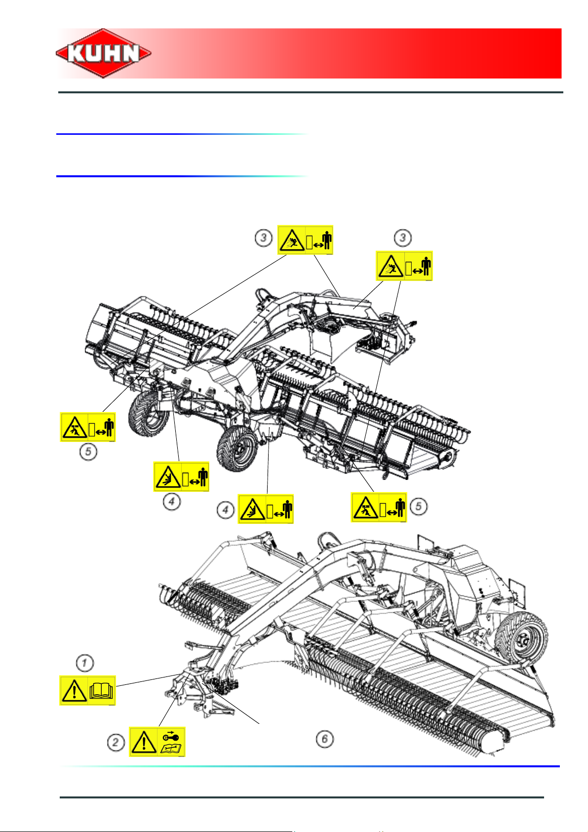
3. Location and description of safety decals on the machine
Location of safety decals
Merger
Merge Maxx 900
Safety
19
Page 22
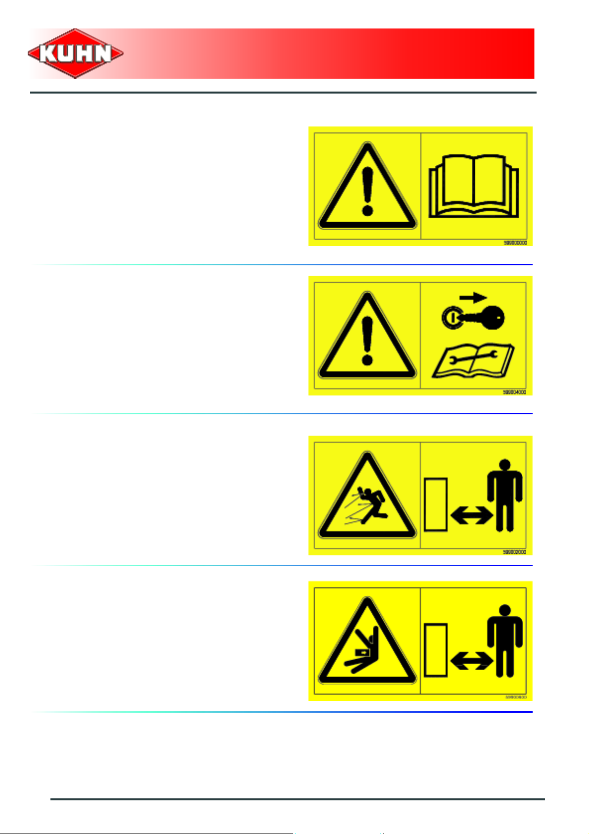
Description of safety decals
Operating instructions (1)
The operators' manual contains all the information
necessary for using the machine safely. It is imperative
to read and comply with all instructions.
Working on the machine (2)
Before leaving the tractor or before adjusting,
maintaining or repairing the machine, disengage the
PTO drive, turn off the engine, remove ignition key and
wait until all moving parts have come to a complete stop
and apply park brake.
Merger
Merge Maxx 900
Projections (3)
Stones and other debris pro jected by the moving parts
can travel a long distance. Always stay at a safe distance
from the machine.
Manoeuvring area (4)
Stay a safe distance from the machine. Crushing hazard.
20
Safety
Page 23

Body crushing (5)
Stay a safe distance from the machine.
Crushing hazard.
Coupling device (6)
Couple the machine to a tractor that is equi pped with a
system for locking the lift arms laterally and vertically.
To drive on roads, respect the attachment height
specified in the operator's manual and lock the lift
linkage.
Merger
Merge Maxx 900
Safety
21
Page 24
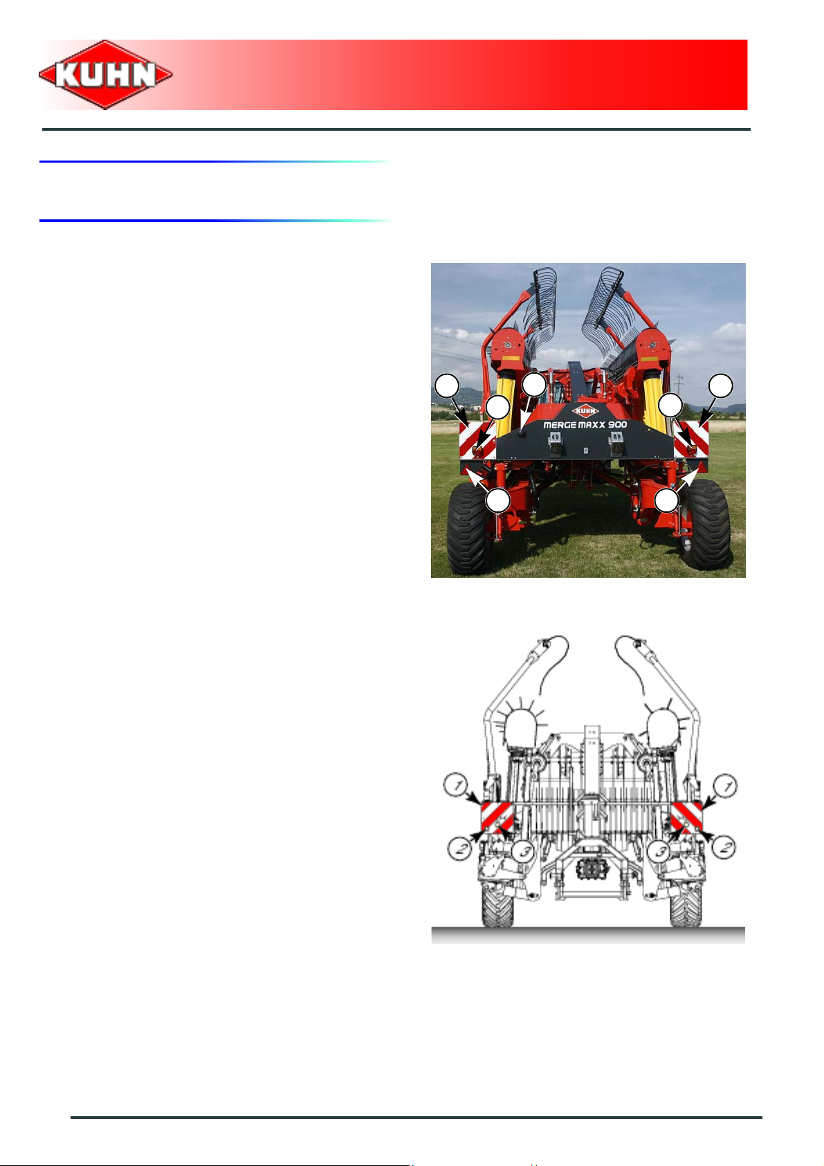
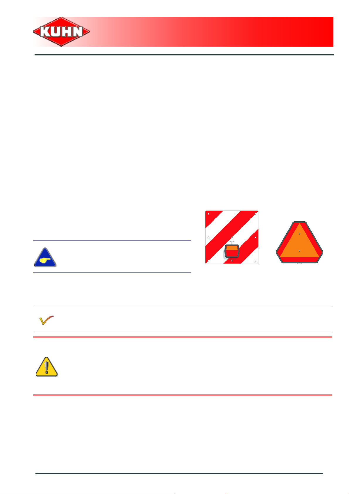
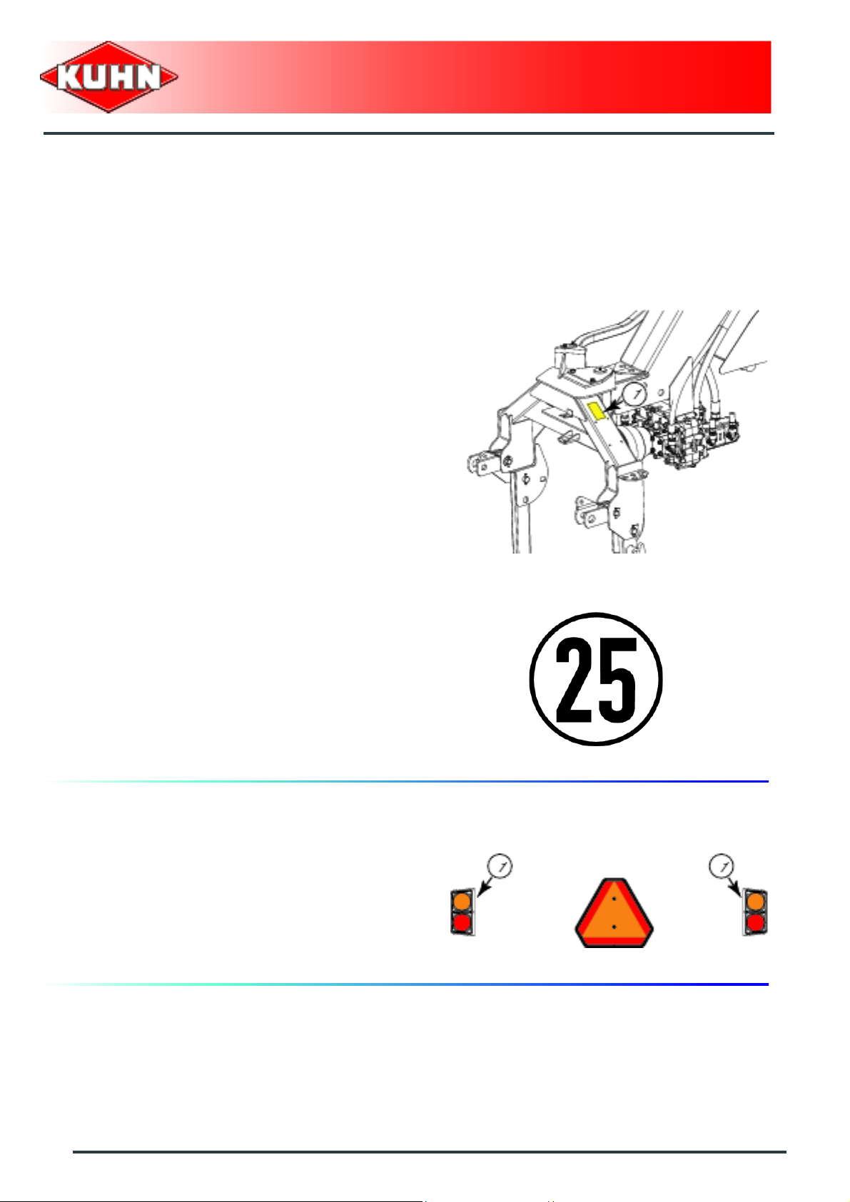
4. Road safety equipment and recommendations
The road safety equipment is mounted in the factory or
by your authorized Kuhn dealer according to current
safety regulations. Always keep to the legal speed limit
for driving a tractor-machine assembly on public roads.
Whatever the speed, we recommend, for everyones'
safety, not to exceed a maximum speed of 25 km/h
(15 mph).
The rear safety device comprises:
- 2 signalling panels (1).
- 2 signalling lights (2) (red light / stop light / turn signal
light).
- 2 red reflectors (3).
- 1 identification plate light (4).
Merger
Merge Maxx 900
4
2
2
11
The front safety device comprises:
- 2 signalling panels (1).
- 2 white reflectors (2).
- 2 white lights (3).
3 3
22
Safety
Page 25
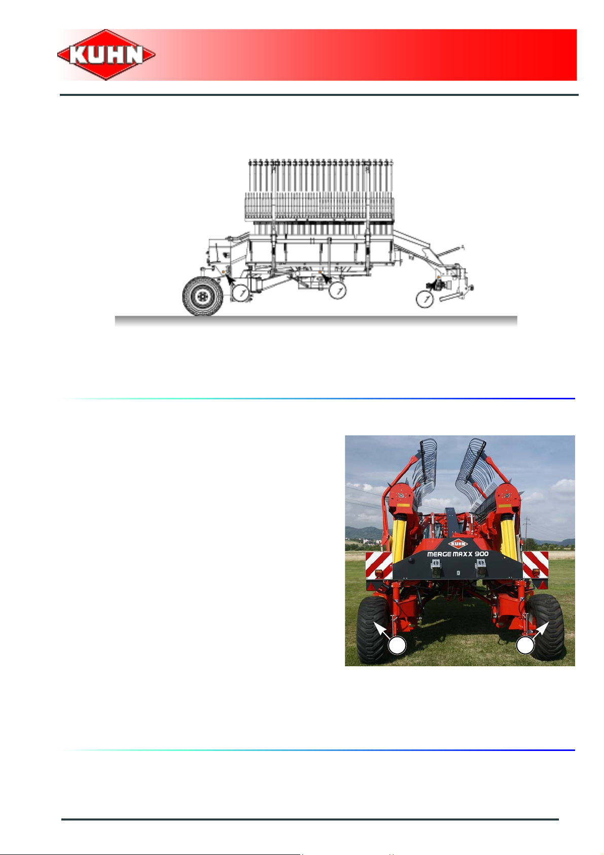
The side device comprises:
- 3 amber reflectors (1) on each machine side.
Merger
Merge Maxx 900
Tyre pressure (1)
- Standard wheels: 2 bar (29 psi)
- Wide wheels: 1.6 bar (23 psi).
- Wheel nut torque:
• 27 daN m (199 lbf ft)
1 1
Safety
23
Page 26
Instructions specific to France
Coupling device (1)
Couple the machine to a tractor that is equipped with a
system for locking the lift arms laterally and vertically.
To drive on roads, respect the attachment height
specified in the operator's manual and lock the lift
linkage.
Merger
Merge Maxx 900
Speed (1)
Always keep to the legal speed limit of 25 km/h (15 mp h)
for driving a tractor-machine assembly on public roads.
Instructions specific to the following
countries: The United States, Canada.
The rear safety device comprises:
- 2 signalling lights (1) (Hazard warning lights).
- 1 support for a SMV emblem (Triangle not supplied).
24
Safety
Page 27
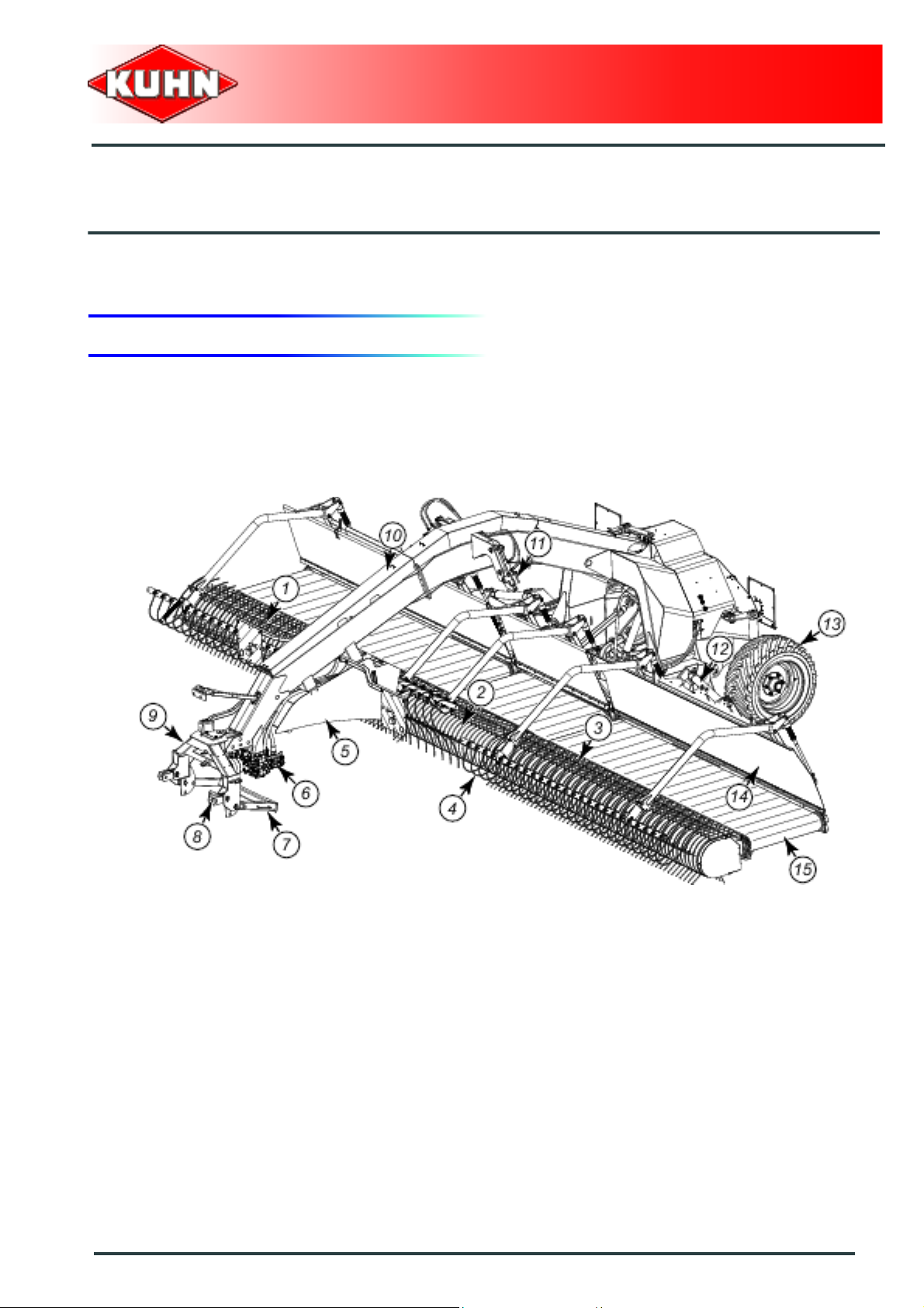
$Machine specifications
1. Description and glossary
0
Merger
Merge Maxx 900
1 : Right pick-up 2 : Central pick-up
3 : Left pick-up 4 : Comb
5 : Hydraulic fluid reservoir 6 : Step up gearbox
7 : Parking stand 8 : Coupling device
9 : Three-point hitch coupler 10 : Drawbar
11 : Transport lock 12 : Folding cylinder
13 : Wheel 14 : Deflector
15 : Conveyor
Machine specifications
25
Page 28

Merger
Merge Maxx 900
2. Technical specifications
Merge Maxx 900
Coupling device 2 point linkage category 2 and 3
Working width (DIN11220)
- Central windrow delivery
- Side windrow delivery
Swath width from 1.40 to 1.80 m (4’7’’ - 5’11’’) (approximately)
Width in working position 9.50 m (31’2’’)
Length in working position 7.13 m (23’5’’)
Height in working position 2.70 m (8’10’’)
10.50 m (34’5’’) (approximately)
9.10 m (29’10’’)
Width in transport position
- with transport wheel: 400/55 - 22.5 14
- with transport wheel: 500/45 - 22.5 14
Length in transport position 7.13 m (23’5’’)
Height in transport position 3.96 m (13’)
Minimum PTO power requirement 50 kW (70 hp)
PTO speed 1000 min
Weight 6600 kg (14550 lb)
Tyres
- Transport wheels
Tyre pressure (Transport wheels)
400/55 - 22.5 14
500/45 - 22.5 14
3.00 m (9’10’’)
3.10 m (10’2’’)
-1
400/55 - 22.5 14 ply
500/45 - 22.5 14 ply
2 bar (29 psi)
1.6 bar (23 psi)
26
Machine specifications
Page 29
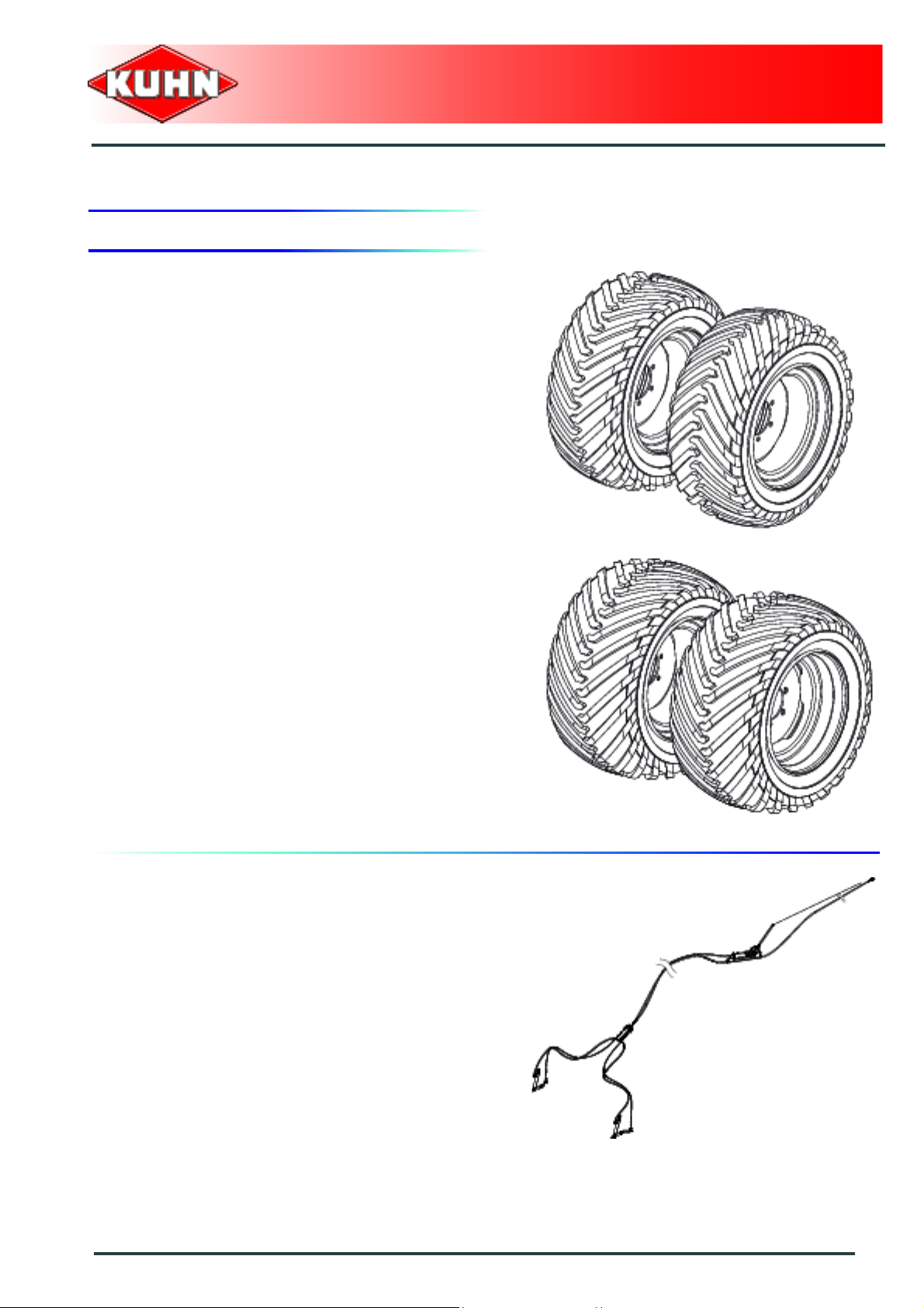
3. Required equipment
Wheels
The machine is factory supplied with the following set of
tires:
- Standard wheels (400/55-22.5 14 ply)
Merger
Merge Maxx 900
or
- Wide wheels (500/45-22.5 14 ply)
Braking system
This equipment is fitted on the machine transport
wheels, in conformity with the legislation in force in the
country concerned.
The machine is factory fitted with one of the following
braking systems:
- Hydraulic braking system.
Machine specifications
27
Page 30
or
- Pneumatic braking system.
Merger
Merge Maxx 900
4. Sound levels
Sound levels have been measured in accordance with the measuring methods as defined in:
NF EN 1553 "Agricultural machinery - Self-propelled, mounted, semi-mounted and trailed - Common
safety recommendations".
Weighted equivalent continuous acoustic pressure level at the driver's seat (closed cabin) L (A) eq:
Tractor only: 71.8 dB(A).
Tractor + machine: 72.2 dB(A).
28
Machine specifications
Page 31
$Putting into service
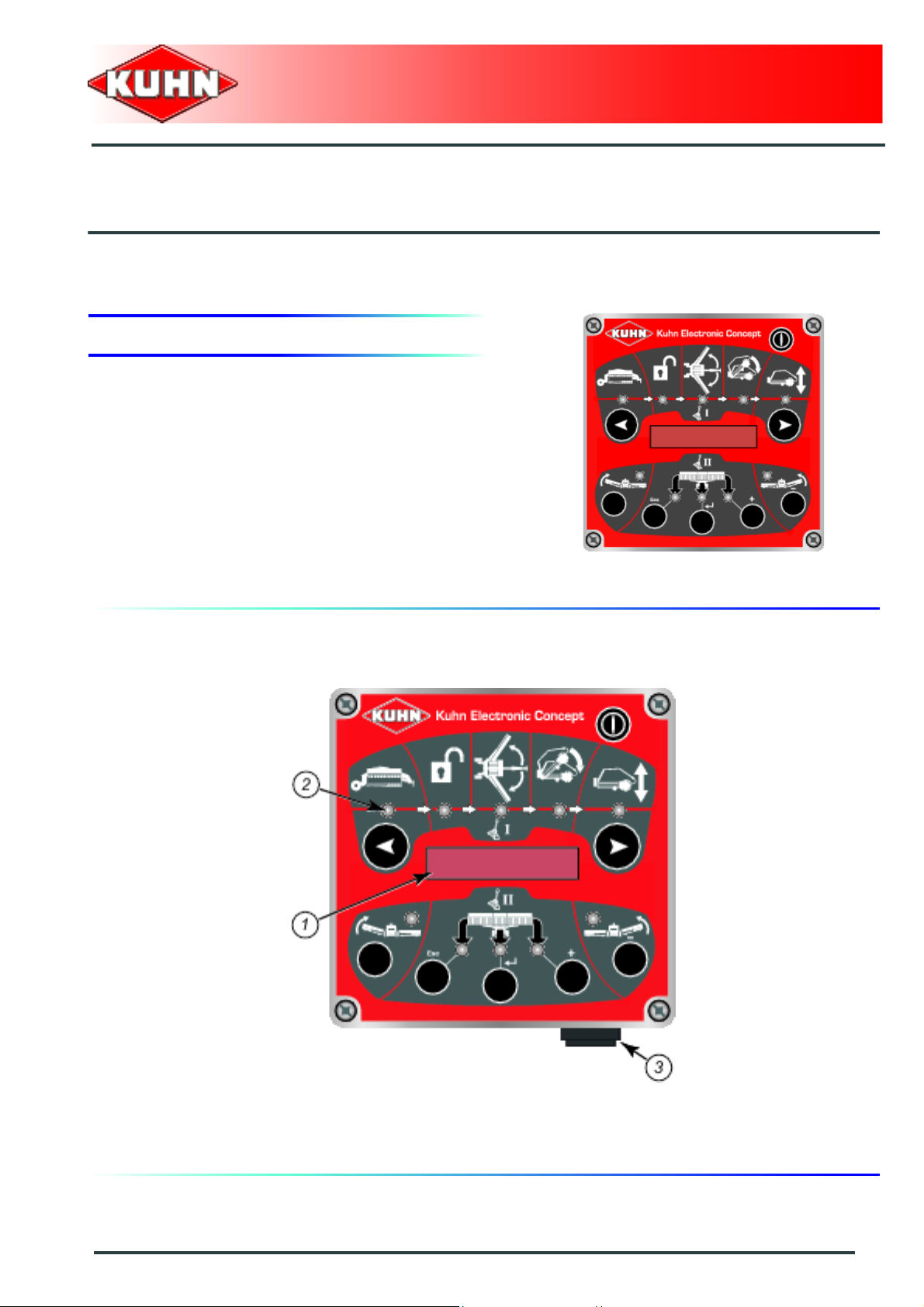
1. Description of control elements
The machine is fitted with a control box to monitor all
functions.
- Model: T15M
Merger
Merge Maxx 900
Description of the box
0
1 : Display
2 : Indicator light
3 : 7-pin CAN connector for the connection to the on board computer
Putting into service
29
Page 32

Description of the functions
0
Merger
Merge Maxx 900
1 : Transport mode
2 : Machine locking/unlocking function
3 : Machine unfolding/folding function
4 : Pick-up pivoting function
5 : Pick-up height adjustment function
6 : Function for setting the left pick-up in headland turn position
7 : Function for selecting the windrow delivery mode
8 : Function for setting the right pick-up in headland turn position
30
Putting into service
Page 33

The control box is made up of 2 areas (a) and (b):
- The functions of area (a) are controlled by tractor
valve I.
- The functions of area (b) are controlled by tractor
valve II.
Merger
Merge Maxx 900
The functions of area (b) are available when the
"Pick up height ajdusmtent" function is activated
(Indicator light (1) on).
Putting into service
31
Page 34

Description of the controls
Key: On / Off
The T15M control box displays the following messages
when started:
- Software version (T15M): v2.5.
Then
- The "ECU" message is displayed when the
connection is activated to the on board comp ut er .
Then
- Software version (M400): v3.0.
Left (1) and right (2) navigation keys:
These keys enable navigating between the various
functions controlled by tractor valve I.
Merger
Merge Maxx 900
Keys for setting the machine into headland turn
position:
- (1) Left pick-up.
- (2) Right pick-up.
Keys for selecting the windrow delivery mode:
- Left windrow delivery (1).
- Central windrow delivery (2).
- Right windrow delivery (3).
- Left and right windrow delivery (1) and (3).
- Windrow delivery two thirds to the left and one third to
the right (1) and (2).
- Windrow delivery two thirds to the right and one third
to the left (2) and (3).
32
Putting into service
Page 35

Particularity:
In certain adjustment modes, the following keys have a
different function:
-Keys - (1) and + (2):
• Enable modifying a mode or a value.
- (3) key:
• Enables validating an adjustment.
- (4) key:
• Enables to quit the adjustment mode or to delete the
error message.
Emergency stop
Merger
Merge Maxx 900
The control box is fitted with an emergency stop for
switching off the module and stopping all electric
functions on the machine actuators.
Swiftly press ON/OFF key to activate
emergency stop.
2. Assembly and fitting
Control box mounting
The control box must be easily accessible from the
tractor cab.
- Clean the glass surface before installation.
- Position holder (1) on the window and lock it using
lever (2).
Putting into service
33
Page 36

Electrical power supply
The box is energized by the tractor's 3-pin socket (DIN
9680, ISO 12369) or the battery power cable supplied.
Number of contact Colour of cable Function
(1) - 82 Brown +12V
(2) - 15/30 Brown +12V
(3) - 31 Blue Ground
Some tractors are factory equipped with a 3pin socket, to prevent any malfunction, check
the polarity of this socket before connecting
the control box.
Check presence of voltage on pin (1).
Merger
Merge Maxx 900
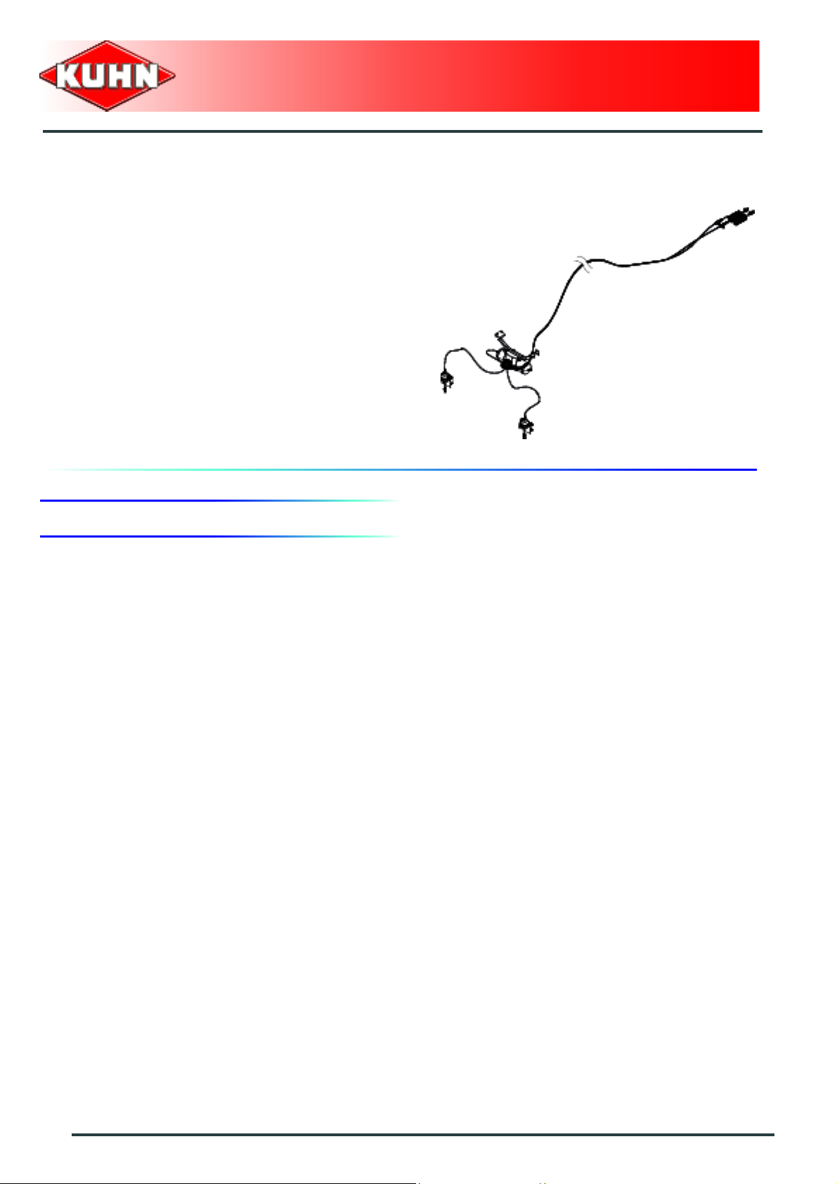
For tractors not fitted with a 3-pin socket, a wiring
harness is supplied with the machine (Part
no. 83233051).
The wiring harness is fitted with 3 fuses:
- 2 ATO type 30 ampere fuses (Part no. 83233031)
(Fuses (1)).
- 1 ATO type 5 ampere fuses (Part no. 83233014)
(Fuse (2)).
For connection to the tractor's own socket,
make sure tractor fuses are of correct
amperage.
34
Putting into service
Page 37

Merge Maxx 900
Harness connection:
- Connect wire (1) to the battery + terminal.
- Connect wire (2) to the battery + terminal.
- Connect wire (3) to the battery - terminal.
Do not connect the wiring harness to the starter connections.
For tractors fitted with a battery isolation switch, the supply cable must be connected just after
the latter.
Never connect the battery charger or carry out welding tasks without having previously
disconnected the 3-pin plug from the control box.
Check that the connectors are in a good condition and clean.
Merger
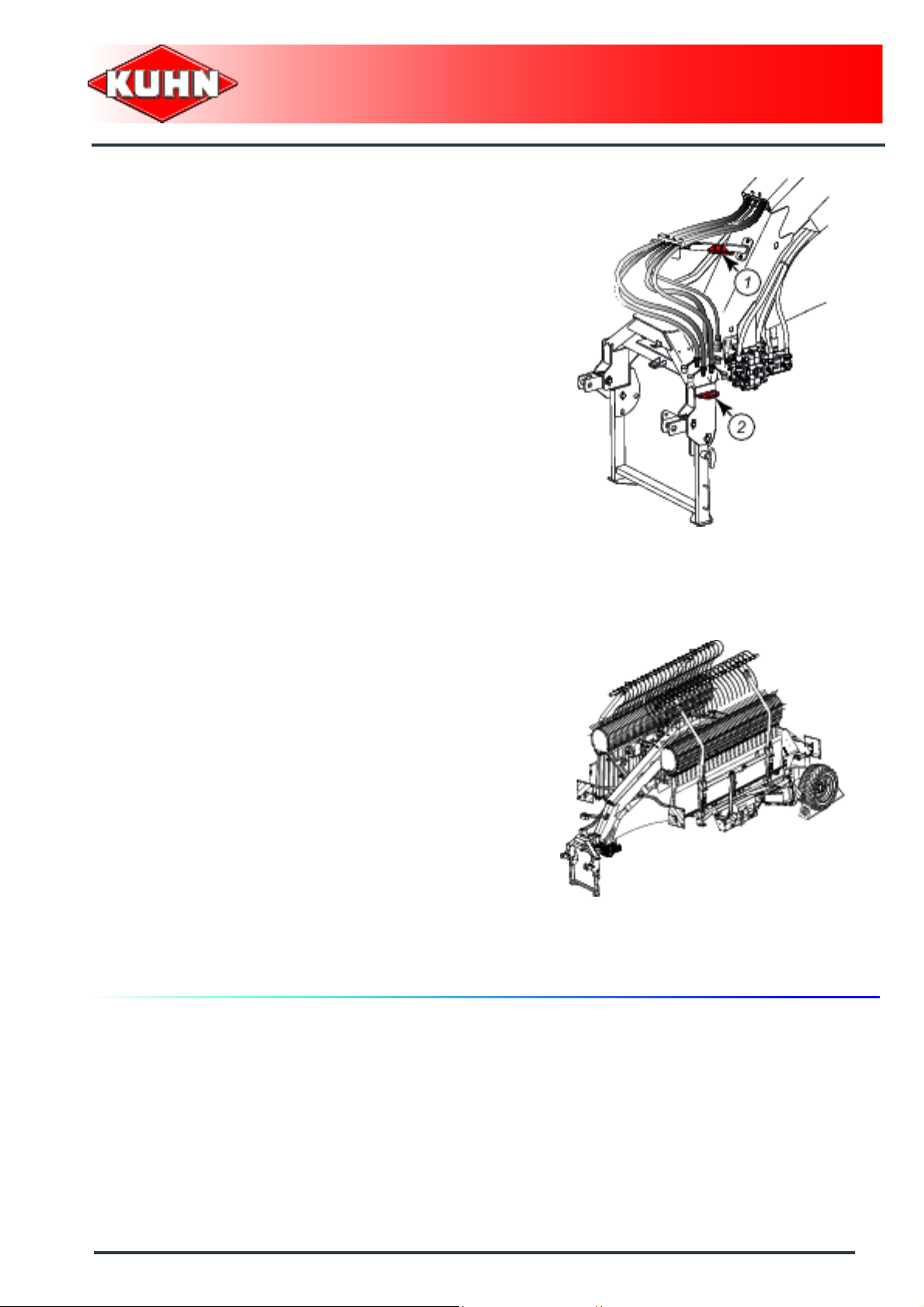
3. Coupling and uncoupling
Description of coupling elements
- A pto shaft drives the machine's hydraulic pump for
driving the pick-ups and the conveyor belts.
- An electric 7-pin plug for the signalling equipment.
- A 3-pin plug for the on-board computer po we r su pply.
- 4 hydraulic hoses connected to the hydraulic valve
bank that controls the various functions.
- 1 hydraulic hose to supply the braking system circuit
(depending upon specification).
- 2 pneumatic hoses to supply the brake actuation
system (depending upon specification).
Putting into service
35
Page 38

Preparing the tractor
The machine adapts to tractors fitted with a 3-point hitch
coupler category 2 or 3.
The tractor must be fitted with lower link
stabilizers.
Merger
Merge Maxx 900
The tractor nominal PTO speed must be 1000 min
-1
.
The tractor must be equipped with:
- 1 double acting valve with float position.
- 1 double acting valve with or without float position.
- An electric 7-pin plug for the signalling equipment.
- A 3-pin electric plug for the control box.
When the machine is fitted with a hydraulic brake
actuation system:
- 1 hydraulic connection for the braking system.
When the machine is fitted with a pneumatic brake
actuation system:
- 2 pneumatic plugs for the braking system.
The front axle load (1) must never, under any
circumstances, be less than 20% of the
tractor's unladen weight.If necessary, add
ballast weights to the front or to the rear to
preserve the steering and braking efficiency.
Hitch pin parallelism
Adjust tractor lift rods so that hitch pins are parallel to the
ground.
36
Putting into service
Page 39

Coupling the machine
- Lower the tractor three-point linkage.
- Place the lower links as close as possible under the
hitch pins.
- Attach lower links to the hitch pins on the inside of the
yokes.
• Category 2 (a)
• Category 3 (b):
Merger
Merge Maxx 900
2 bushes diameter 37 mm (1.45’’) are supplied
with the machine.
- Secure each hitch pin with lynch pin.
- Raise tractor lift linkage to free parking stand.
- Pull on handle (1) to unlock parking stand (2).
- Fold parking stand (2) upwards and lock it in place.
- Remove and store wheel chocks on their holders.
Putting into service
37
Page 40

Hydraulic connections
The tractor must be equipped with 2 double acting
valves.
Connect hydraulic hoses (a) and (b) of diameter 16 mm
(0.6’’) on the same tractor double acting valve.
Hoses (a) and (b) supply the following cylinders:
- Transport lock cylinders.
- Machine unfolding/folding cylinders.
- Pick-up pivot cylinders.
- Pick-up height adjustment cylinders.
Connect hydraulic hoses (c) and (d) of diameter 20 mm
(0.8’’) on the same tractor double acting valve.
This valve must have a floating position.
Merger
Merge Maxx 900
Hoses (c) and (d) supply the following cylinders:
- Cylinders for setting the machine into headland turn
position.
After connecting the hoses, check that there is no risk of
catching them during operation.
Before connecting hoses to the tractor
hydraulics, ensure that tractor and machine
circuits are not under pressure.
Before disconnecting a hose, depressurize
the hydraulic circuit.
38
Putting into service
Page 41

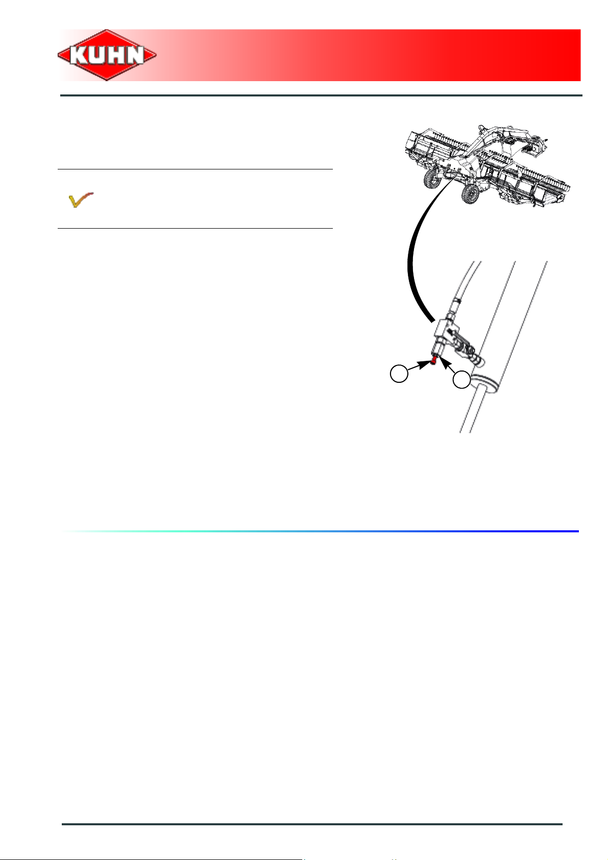
Connections for the hydraulic braking (depending upon specification)
Connect hydraulic hose for braking system to the tractor
"trailor brake" coupler.
After connecting the hose, check that there is no risk of
it getting caught during operation.
Check that the brakes work correctly.
Pneumatic braking connections
(depending upon specification)
Merger
Merge Maxx 900
Check connector cleanliness prior to
connecting the hoses.
- Connect the coiled air brake hoses to the tractor.
Respect hose colour when connecting them:
- Red (a): Feed line.
- Yellow (b): Actuating line.
After connecting the lines, check that there is no risk of
them getting caught in operation.
- Check that the brakes work correctly.
When the braking hoses are not connec ted to
the tractor's braking system, the machine's
brakes are automatically engaged.
- Press valve (1) to disengage brakes by hand.
- Pull valve (1) to engage brakes by hand.
A maximum of 3 brake engagement/
disengagement cycles are possible with the
volume of air contained in the container.
Putting into service
39
Page 42
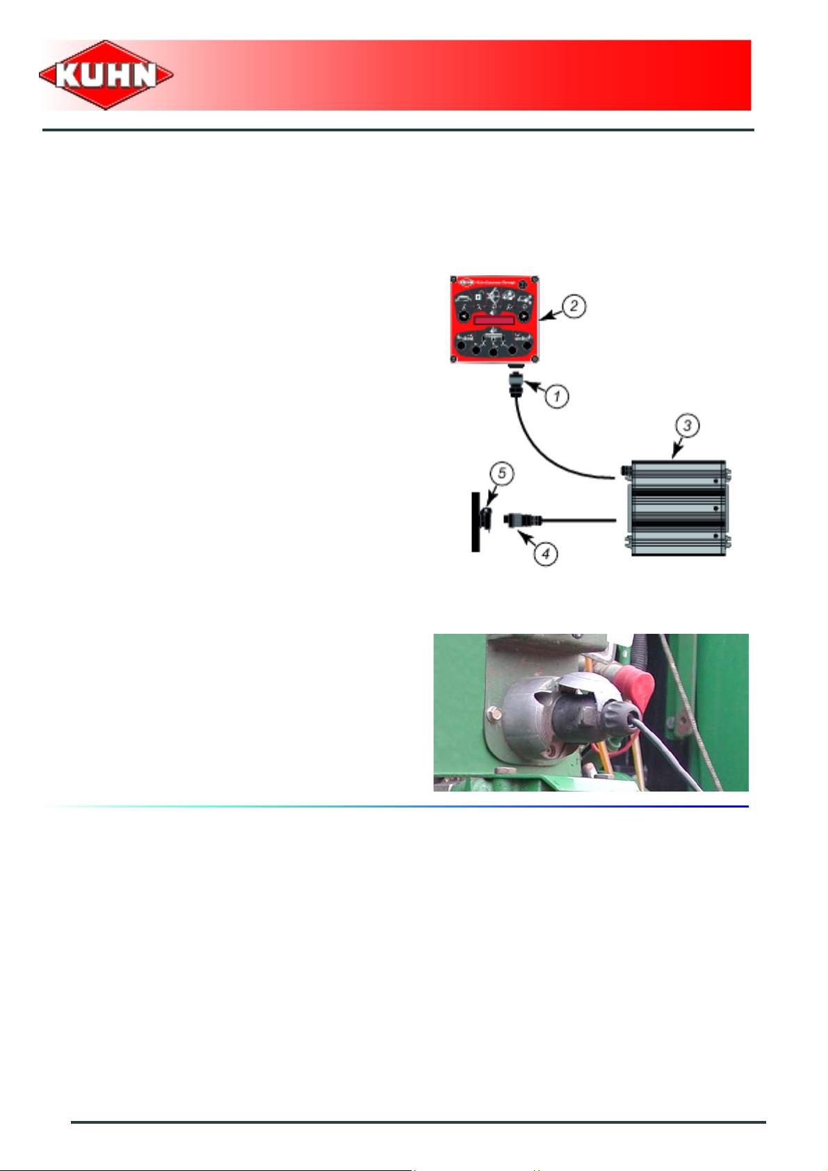
Electrical connections
Control box
- Connect 7-pin plug (1) of module (3) to control box (2).
- Connect the module M400 (3) wiring harness (4) to
the tractor 3-pin plug (5).
Merger
Merge Maxx 900
Lighting
- Connect 7-pin plug to the tractor.
After making the connections, check that there is no risk
of the cables being caught during operation.
40
Putting into service
Page 43
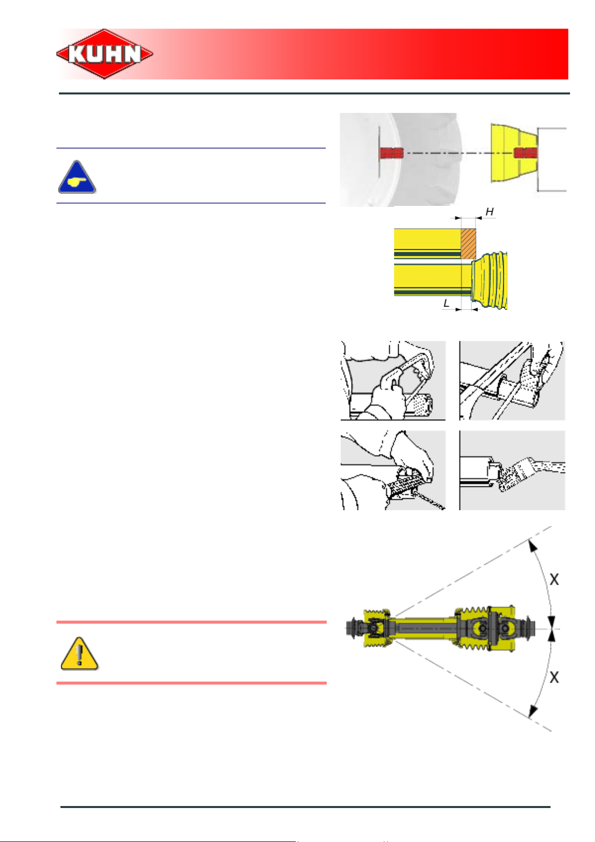
Primary PTO shaft
Make sure that the PTO shaft is correctly
adjusted, to avoid premature wear and tear.
The tractor PTO stub must rotate at a speed of 1000 min-1.
Separate the two half PTO shafts and connect them to
the machine's input shaft and to the tractor PTO stub.
Check the length of the PTO shaft:
- Check the maximum overlap when tractor and
machine PTO stubs are in line.
- When the PTO shaft is in its maximum overlap
position (retracted), tubes should not butt against the
yokes. As a safety measure, a clearance (L) of at least
10 mm (0.4’’) must be maintained.
- When the PTO shaft is in its maximum extended
position, the tube overlap must be more than
250 mm (10’’).
Merger
Merge Maxx 900
If this is not the case:
- Mark length (H) to cut when the transmission is the
maximum overlap position
- Shorten the guard tubes and the transmission tubes
by the same length.
- Bevel and clean the tubes.
- Grease the inside of the outer tube.
Never operate the PTO shaft at an angle X exceeding
30°.
To avoid serious accidents, the PTO drive
shaft guards must be properly in place and
fixed with the chains provided.
Putting into service
41
Page 44

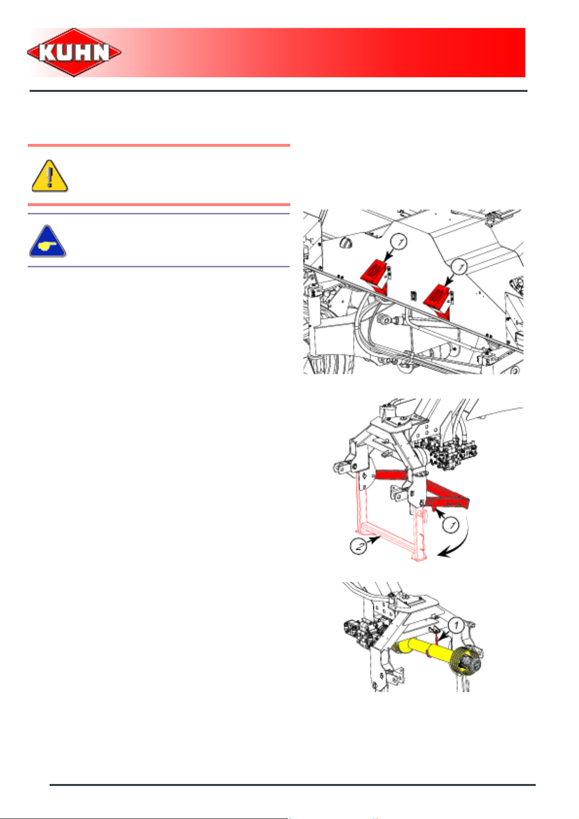
To avoid serious accidents, the PTO drive
shaft guards must be properly in place and
fixed with the chains provided.
Attach PTO shaft guard chain in hole (1) on machine
side.
Immediately replace any worn or damaged
guard.
Merger
Merge Maxx 900
1
Unfold pto shaft support (1).
42
Putting into service
Page 45

Adjusting the machine
Lateral adjustment of the lower linkage arms
Balance the play on either sides of the lift linkage and
lock lower link stabilizers.
Merger
Merge Maxx 900
Frame height
- Lower the tractor lift linkage so that hitch pins are at a
distance H = 630 mm (2’1’’) from the ground.
Putting into service
43
Page 46
Uncoupling the machine
Park the machine on an even fairly level
ground.
Preferably park the machine in transport
position.
- Block machine with wheel chocks (1).
Merger
Merge Maxx 900
- Release and lower parking stand (2).
- Secure parking stand using lock (1).
- Uncouple and place PTO shaft in support (1).
44
Putting into service
Page 47
- Disconnect and store brake system hydraulic hoses
on holder.
- Disconnect and store hydraulic hoses on holder (2).
- Disconnect and store signalling electric plug on holder
(2).
- Disconnect and store module electric supply plug.
- Disconnect and store control box in a dry and clean
place.
Merger
Merge Maxx 900
- Lower the tractor three-point linkage to rest the
machine on the ground.
- Release the lower links.
- Lower the tractor three-point linkage.
The machine is uncoupled.
Putting into service
45
Page 48

$Instructions for transport
Before placing the machine into transport
position:
- Wait until the rotating parts have come
to a complete stop.
- Check that nobody is within the machine
pivoting area.
- If there is someone, make sure the
person moves away.
1. Putting the machine into transport position
Merger
Merge Maxx 900
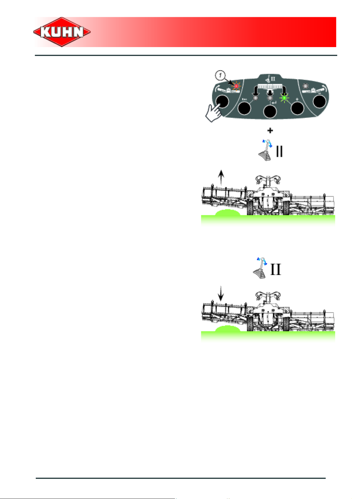
From the working position:
- Place the machine in headland turn position (Valve II).
- Operated hydraulic valve during 5 seconds to position
the central pick-up in transport position.
The side pick-ups cannot be raised if the
machine is not in headland turn position.
The central pick-up must be in transport
position.
The screen flashes.
- Press for approximately 1 second on the navigation
key:
• Indicator light (1) comes ON.
• - - 3 - - is displayed on the screen.
- Operate tractor hydraulic valve I:
• The side pick-ups lift.
46
Instructions for transport
Page 49

- Press for approximately 1 second on the navigation
key:
• Indicator light (1) comes ON.
• - - 2 - - is displayed on the screen.
- Operate tractor hydraulic valve I:
• The machine folds.
Merger
Merge Maxx 900
- Press for approximately 1 second on the navigation
key:
• Indicator light (1) comes ON.
• - - 1 - - is displayed on the screen.
- Operate tractor hydraulic valve I:
• The machine locks.
Check that transport locks (1) are fully
engaged.
Instructions for transport
47
Page 50

- Press approximately 1 second on key (a):
• Indicator light (1) flashes.
• The hour counter is displayed.
• all machine functions are deactivated.
- Press on the button ON/OFF (b).
Merger
Merge Maxx 900
The machine is in transport position.
Never engage the tractor PTO drive when the
machine is in transport position.
48
Instructions for transport
Page 51

2. Conformity with the road regulations
Before driving the machine on public roads,
ensure that the machine complies with
current highway code regulations.
Check that the light boards are clean and that the lighting
equipment functions before transporting the machine on
public roads.
Immediately replace any worn or damaged
signalling panels or lights.
Merger
Merge Maxx 900
Check that transport locks (1) are fully
engaged.
Instructions for transport
49
Page 52

$Instructions for work
Before placing the machine in working
position:
- Check that nobody is within the machine
pivoting area.
- If there is someone, make sure the
person moves away.
1. Putting the machine into work position
Merger
Merge Maxx 900
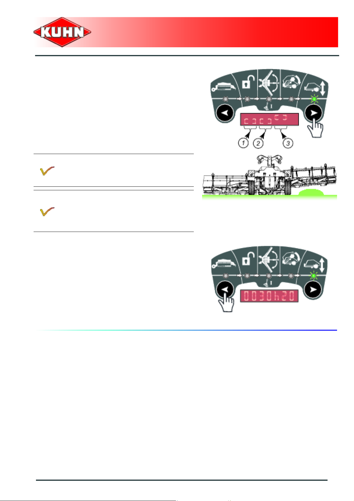
From the transport position:
- Press on the button ON/OFF.
• Indicator light (1) flashes.
Wait for the hour counter to appear on the screen.
- (a): hour (0 to 9999).
- (b): minute (0 to 59).
If the hour counter is not displayed, contact your
Kuhn dealer.
- Press for approximately 1 second on the navigation
key:
• Indicator light (1) comes ON.
• - - 1 - - is displayed on the screen.
- Operate tractor hydraulic valve I:
• The machine is unlocked.
50
Instructions for work
Page 53

- Press for approximately 1 second on the navigation
key:
• Indicator light (1) comes ON.
• - - 2- - is displayed on the screen.
- Operate tractor hydraulic valve I:
• The machine unfolds.
Merger
Merge Maxx 900
- Press for approximately 1 second on the navigation
key:
• Indicator light (1) comes ON.
• - - 3 - - is displayed on the screen.
- Operate tractor hydraulic valve I:
• The pick-ups are lowered.
The 1, 2 and 3 modes are active during 60
seconds.
After 60 seconds, the screen flashes.
- Press shortly on arrow keys to reactivate
the mode during 60 additional seconds.
- Without an impulse, the control box
automatically deactivates the function and
switches to the transport mode.
Instructions for work
51
Page 54

- Press for approximately 1 second on the navigation
key:
• Indicator light (1) comes ON.
• The hour counter is displayed.
• The work functions are activated.
- Activate tractor hydraulic valve II to lower the pickups.
Merger
Merge Maxx 900
The machine is in working position.
52
Instructions for work
Page 55

2. Adjustments in working position
Before making any adjustment:
- Check that nobody is within the machine
pivoting area.
- If there is someone, make sure the
person moves away.
Adjusting the pick-up working height
- Select the "Pick-up height adjustment" function using
navigation keys:
• Indicator light (1) comes ON.
• The hour counter is displayed.
- Activate tractor hydraulic valve I to adjust the pick-up
height.
Merger
Merge Maxx 900
Tine to ground distance D can vary from 0 mm to
110 mm (0’’ - 4.33’’).
The pick-up height can be adjusted any time
during work.
Activate tractor hydraulic valve I to adjust the
pick-up height.
Indicator (1) enables to visualize the pick-up working
height.
The difference between 2 notches corresponds
to a 20 mm (0.8’’) variation in the working height
of the pick-ups.
Instructions for work
53
Page 56

Adjusting the aggressiveness of the combs
Various settings are possible:
Adjustment 1:
- Loosen screw (1).
- Remove screw (2).
- Place comb in the required position:
• Position (a): More aggressive position.
• Position (b): Intermediate position.
• Position (c): Less aggressive position.
- Repeat procedure on each comb .
- Fit screw (2).
- Tighten screw (1).
• Torque : 8.5 daN m (63 lbf ft).
Merger
Merge Maxx 900
Adjustment 2:
- Loosen nuts (1).
- Place comb in the required position.
- Tighten nuts (1).
• Torque : 2.5 daN m (18 lbf ft).
54
Instructions for work
Page 57

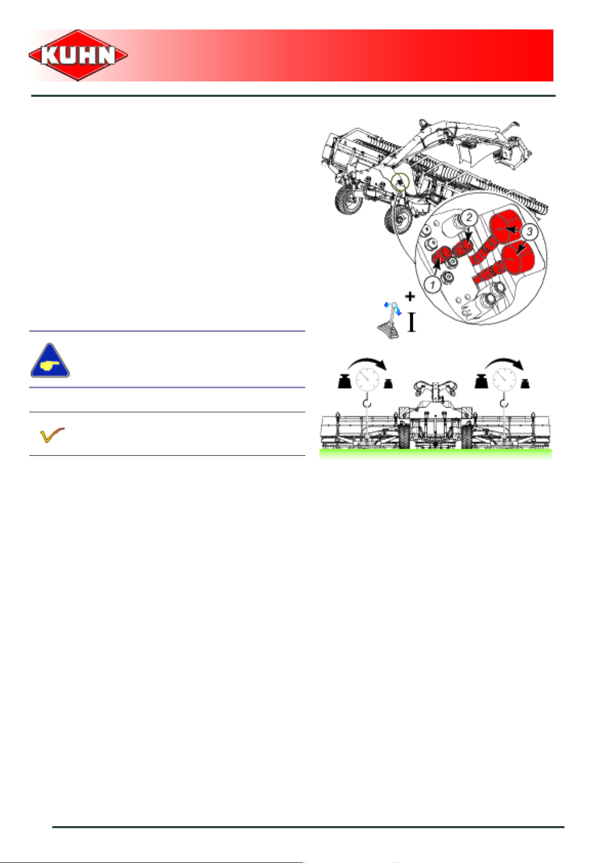
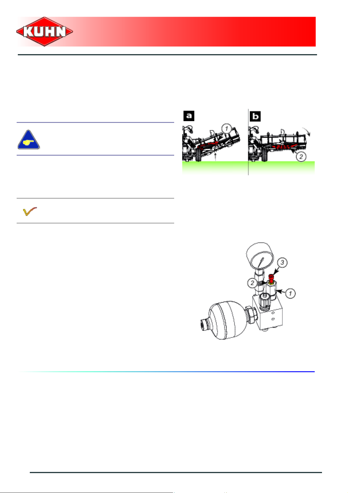
Ground pressure adjustment of the side pick-ups
The side pick-up ground pressure is obtained by 2 hyd ropneumatic accumulators.
By modifying the accumulator pressure, the side pick-up
ground pressure varies.
The pressure must be adapted to the nature and
moisture degree of the ground.
Conditions required:
- The pick-ups are fully raised.
- Select the "Pick-up height adjustment"
function using navigation keys (1).
The machine hydraulic suspension circuit is
pressurized at the factory at 135 bar
(1958 psi):
- max.: 140 bar (2030 psi)
- minimum: 130 bar (1885 psi)
Never adjust machine to a pressure not
comprized between the limit values.
Merger
Merge Maxx 900
1
- Park the machine on an even fairly level ground:
• All pick-ups must rest on the ground.
- Select the "Pick-up height adjustment" function using
navigation keys.
- Activate the tractor hydraulic valve to fully raise the
pick-ups
- Select the "Machine locking/unlocking" function using
the navigation keys.
- Indicator light (1) comes ON.
The function is activated during 60 seconds.
After 60 seconds, the screen flashes.
- Press shortly on arrow keys to reactivate
the mode during 60 additional seconds.
Without an impulse, the control box
automatically deactivates the function and
switches to the transport mode.
Instructions for work
55
Page 58
Ground pressure reduction
Increase pressure in the hydro-pneumatic accumulators
to reduce the pick-up ground pressure:
- Check that valves (1) and (2) are shut-off.
- Operate and maintain hydraulic valve I control lever to
pressurize the circuit.
- Slowly open hydraulic unit valve (2).
- Check pressure increase on gauges (3).
- When the required pressure is reached, close the
valve (2).
Merger
Merge Maxx 900
Tighten valve by hand.
When proceeding to the adjustment, the
pressure exceeds the required value, refer to
"Ground pressure increase" section.
56
Instructions for work
Page 59

Ground pressure increase
Reduce pressure in the hydro-pn eumatic accumulators
to increase pick-up ground pressure:
- Check that valves (1) and (3) are shut-off.
- Place hydraulic valve control lever I in floating position
(or in the "oil returns to the tractor tank" position).
- Slowly open hydraulic unit valve (1).
- Check pressure decrease on gauges (2).
- When the required pressure is reached, close the
valve (1).
Tighten valve by hand.
When proceeding to the adjustment, the
pressure is below the required value, refer to
"Ground pressure decrease" section.
Merger
Merge Maxx 900
When the pressure in the ground pressure
circuit goes below 125 bar (1812 psi), an
alarm message is displayed on the control
box.
In the direction of travel:
- ’’ Press L ’’ = Pressure in the ground
pressure circuit left side.
- ’’ Press R ’’ = Pressure in the ground
pressure circuit right side.
Immediately increase the ground pressure in
the concerned circuit to the recommended
value as soon as the message appears.
See section: ’’ Ground pressure adjustment of
the side pick-ups ’’
Press on the control box "Esc" key to delete the
message momentarily.
Instructions for work
57
Page 60
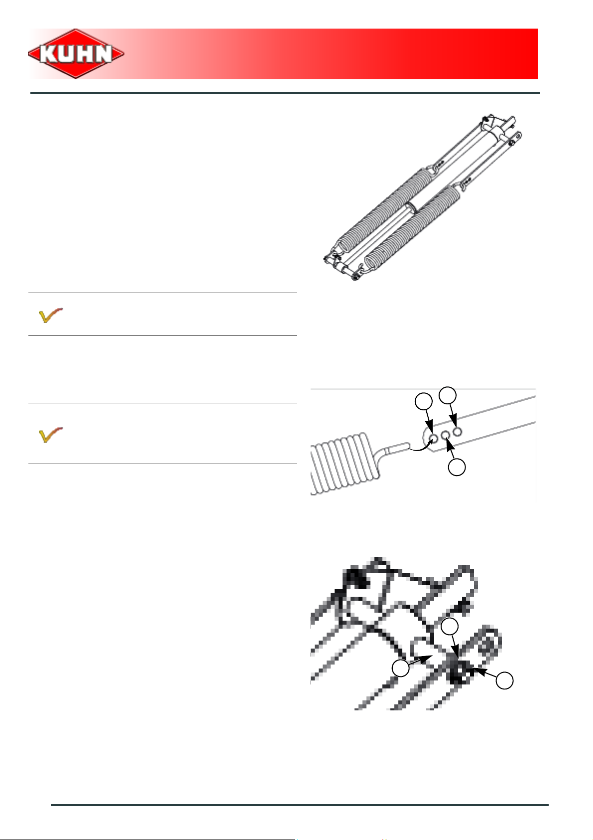
Adjustment of the central pick-up ground
pressure
2 springs enable adjusting the central pick-up ground
pressure.
Adjustment
The pressure must be adapted to the na ture and
moisture degree of the ground.
Merger
Merge Maxx 900
The springs are factory set to a minimum ground
pressure (1).
Position (2):
- Ground pressure increase (+ 34 kg (75 lb).
Position (3):
- Ground pressure increase (+ 68 kg (15 0 lb).
- Raise the central pick-up:
• See section: ’’
- Shut-off the central pick-up cylinder valve.
- Remove roll pin (1) and washer (2).
- Remove pin (3).
- Place the springs in the hole corresponding to the
required setting.
• The 2 springs must adjusted to the same measure.
- Reinstall pin (3).
- Reinstall washer (2) and roll pin (1).
- Open the central pick-up cylinder valve
Central windrow delivery ’’.
1
3
2
2
3
1
58
Instructions for work
Page 61
Adjustment of the balancing pressure of the side pick-ups
During the first adjustment, increase
pressure to 175 bar (2538 psi) and then
reduce pressure to (0 bar).
Repeat procedure 5 times to bleed the circuit.
- Check that valve (1) is shut-off.
- Operate tractor hydraulic valve II in the headland turn
position direction:
• The side pick-ups lift.
The pick-up holding frame (2) must be at
travel end against side arm (3).
Merger
Merge Maxx 900
- Press hydraulic valve control lever II to pressurize the
circuit.
- Slowly open valve (1).
- When the pressure reaches 175 bar (2538 psi) bar on
the pressure gauge, close the valve.
Tighten valve by hand.
Adjust both sides to the same setting.
Reducing the balancing pressure of the side pick-ups
- Activate tractor hydraulic valve II to lower the pickups.
- Place hydraulic valve control lever II in floating
position (or in the "oil returns to the tractor tank"
position).
- Slowly open valve (1).
- Shut-off valve when the pressure reaches the
required value on the manometer.
Tighten valve by hand.
Instructions for work
59
Page 62
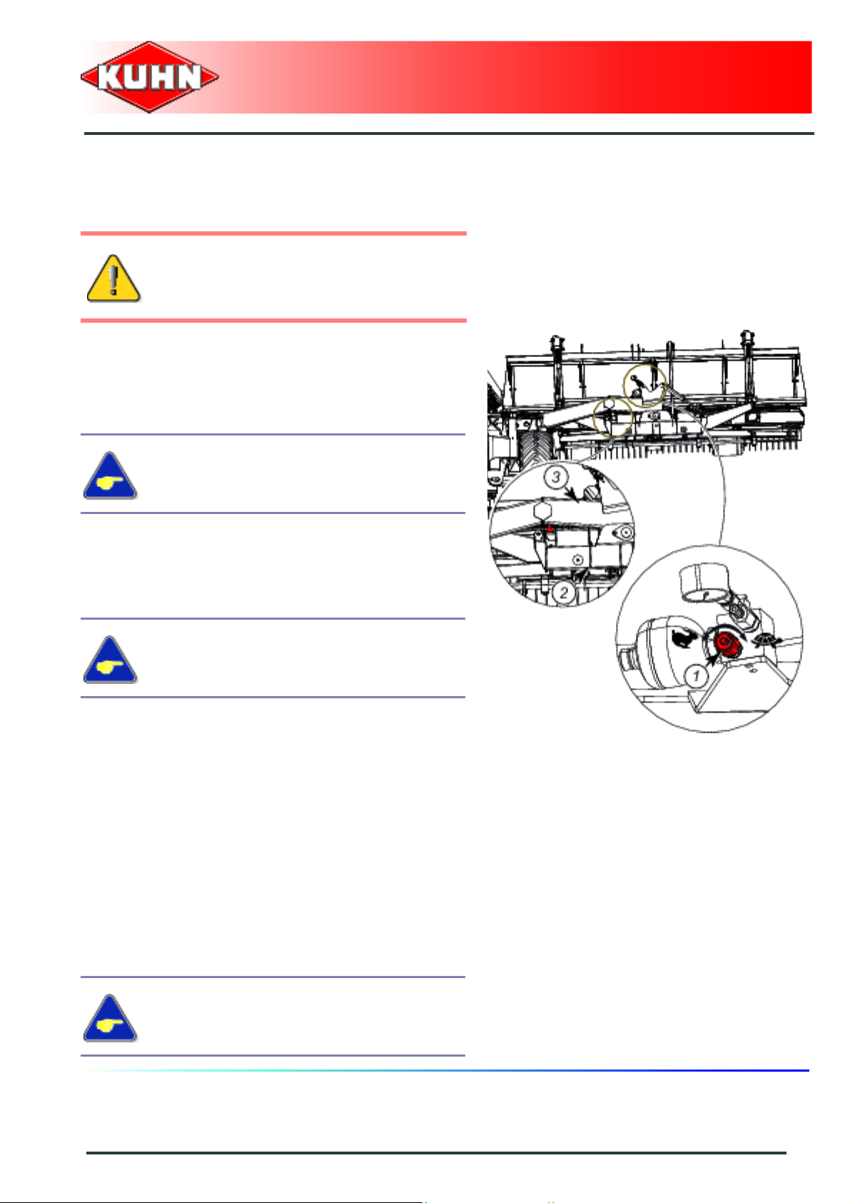
Adjusting the synchronisation of the side
arm lift and the pick-up holding frame
rotation
The pick-up holding frame (2) rotation must
be made after raising side arm (1):
- a: Side arm lift.
- b: Rotation of the pick-up holding frame.
Merger
Merge Maxx 900
The sequencing valve is factory preset at (1).
To delay the rotation movement of the pick-up holding frame:
- Loosen counter nut (2).
- Tighten screw (3) by an eighth of a turn.
- Check movement synchronisation.
- Repeat procedure if necessary .
- Tighten the counter nut.
To put the pick-up holding frame rotation movement forward:
- Loosen counter nut (2).
- loosen screw (3) by an eighth of a turn.
- Check movement synchronisation.
- Repeat procedure if necessary .
- Tighten the counter nut.
60
Instructions for work
Page 63
Synchronization of the lift of the side pick-
ups with regards to the central pick-up
The lift of the 3 pick-ups must occur
approximately at the same moment.
The sequencing valve is factory preset at (1).
To delay the central pick-up raising:
- Loosen counter nut (1).
- Tighten screw (2) by an eighth of a turn.
- Check movement synchronisation.
- Repeat procedure if necessary.
- Tighten counter nut (1).
Merger
Merge Maxx 900
To advance the central pick-up raising:
- Loosen counter nut (1).
- loosen screw (2) by an eighth of a turn.
- Check movement synchronisation.
- Repeat procedure if necessary.
- Tighten counter nut (1).
2
1
Instructions for work
61
Page 64

Adjustment of the time delay when
inverting the conveyor belt direction of
rotation (t2)
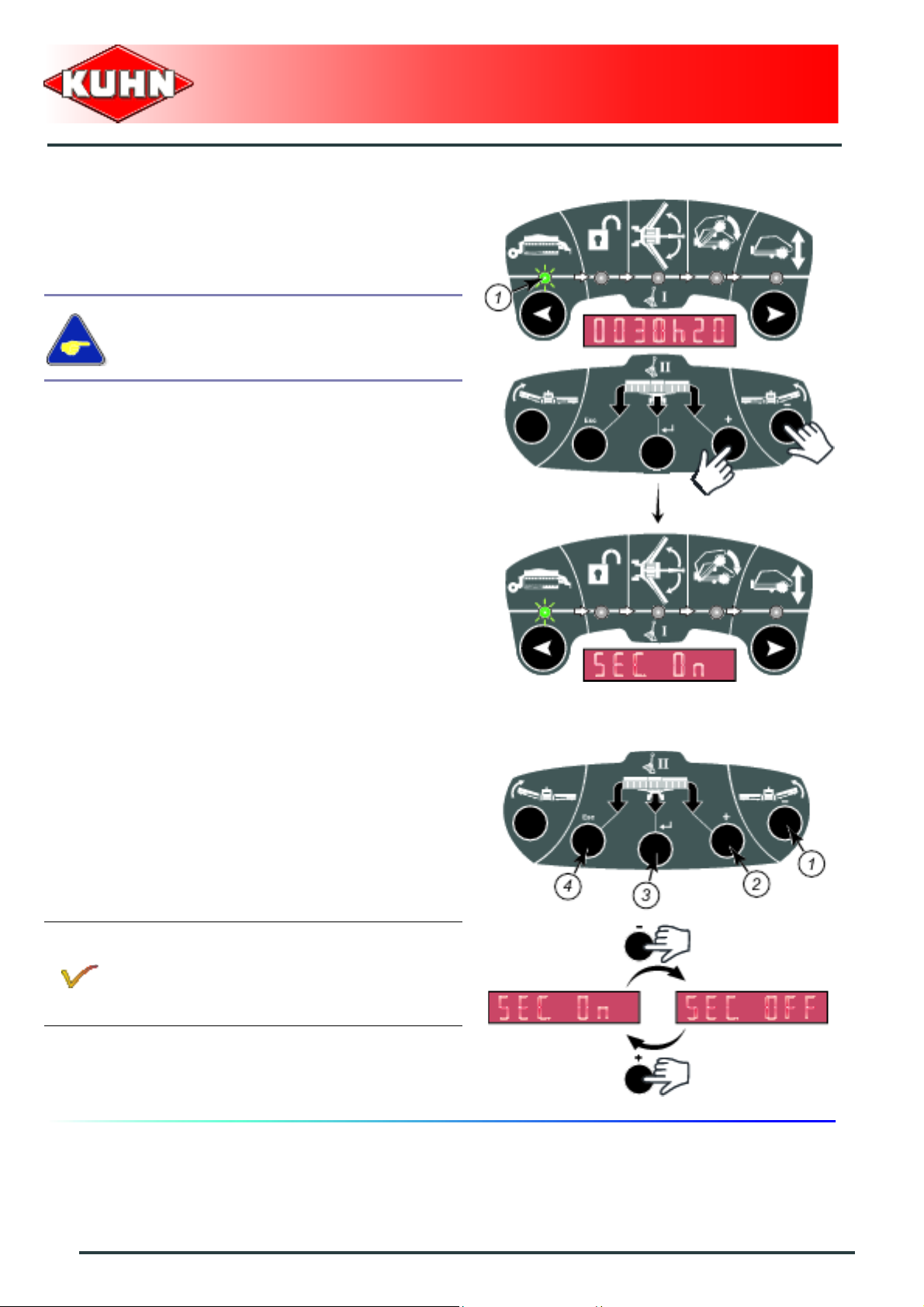
To access the time delay adjustment:
- Select transport mode:
• Indicator light (1) flashes.
- Simultaneously press keys + and - for approximately
5 seconds:
• The message "SEC. ON" is displayed.
Merger
Merge Maxx 900
- Shortly press navigation key:
• The message "t2 . 5" is displayed.
Adjusting the central pick-up time delay to the intermiate position (t3)
- Shortly press navigation key:
• The message "t3 . 5" is displayed.
62
Instructions for work
Page 65

Modification of the t2 or t3 value
- Press key - (1) to reduce the time delay:
• 2 seconds (minimum).
or
- Press key + (2) to increase the time delay:
• 10 seconds (max.).
- Press on validation key (3) to save the modifications
and return to the transport mode.
The modifications are saved permanently:
- Press "Esc" key (4) to quit without saving the
modifications and return to the transport mode.
Merger
Merge Maxx 900
Instructions for work
63
Page 66

Steering system adjustment
Should the transport wheels hit an obstacle,
check that the steering system is not
damaged.
Check the wheel toe-in (2.4°):
- Measure distance A on the front edges of the wheel
rims.
- Measure distance B on the rear edge of the wheel
rims.
• B = A + 24 mm (1’’).
Merger
Merge Maxx 900
The procedure consists in adjusting the wheel
alignment and toe-in.
Remove steering rod (1):
- Remove nut (2).
- Remove screw (3).
- Remove roll pin (4).
- Remove washer (5)
- Remove pin (6).
- Position headstock (1) at 90° in relation to beam (2).
64
Instructions for work
Page 67

- Pivot areas S and S’ in an angle X of 90° in relation to
beam (1).
Adjusting the wheel alignment ( Perform the operation
on each side of the machine ):
- Loosen counter nut (1).
- Remove nut (2).
- Remove screw (3).
- Remove roll pin (4).
- Remove washer (5)
- Remove pin (6).
- Adjust yoke (7).
- Reinstall pin (6).
- Check wheel parallelism.
Adjusting the wheel toe-in:
- Remove pins (6).
- Tighten yokes by 3.5 turns.
- Check the wheel toe-in (2.4°), B = A + 24 mm (1’’).
Readjust if necessary.
- Reinstall pins (6).
- Reinstall washers (5)
- Reinstall roll pins (4).
- Reinstall bolts (3).
- Reinstall nuts (2).
- Tighten counternuts (1).
Merger
Merge Maxx 900
Reinstall steering rod (1):
- Loosen counter nut (2).
- Adjust yoke (3).
- Reinstall pin (4).
- Tighten counter nut (2).
- Reinstall washer (5)
- Reinstall roll pin (6).
- Reinstall screw (7).
- Reinstall nut (8).
Instructions for work
65
Page 68

3. Machine use
Before working:
- Check that nobody is within the machine
pivoting area.
- If there is someone, make sure the
person moves away.
- The machine is fitted with a steering device to:
• allow the machine to follow the same track as the
tractor.
• Facilitate headland turn manoeuvres and speed up
its realignment with regards to a machine not
equipped with this device.
• drive onto a field difficult to access.
Merger
Merge Maxx 900
The headstock is designed to turn at an angle
of maximum 65 degrees to the right of left.
To preserve the steering system, never
exceed this angle.
Groundspeed
The machine can work at a speed of up to
15 km/h (9 mph) in very good working conditions.
Groundspeed must be adapted to the encountered
working conditions.
66
Instructions for work
Page 69

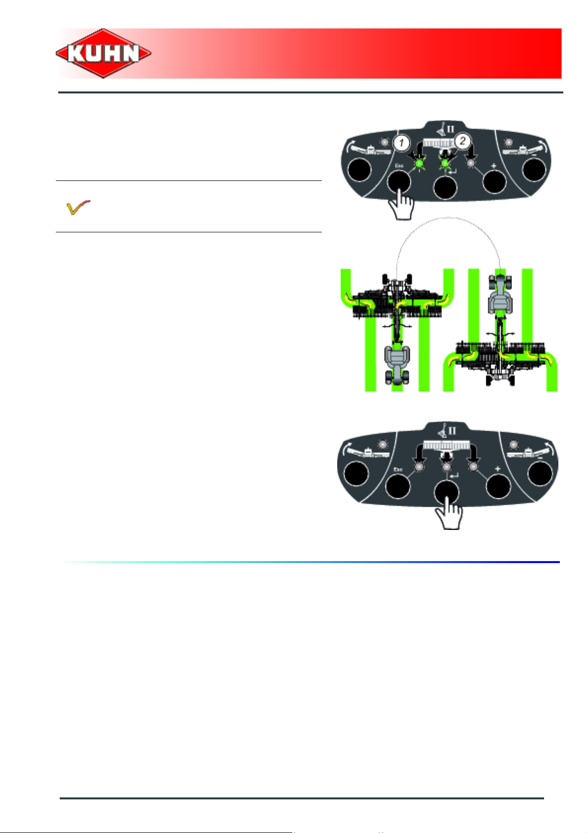
Selecting the windrow delivery mode
Left windrow delivery
- Press approximately 1 seconds on selection key:
• The indicator light flashes for the whole period
during which the conveyor belt direction of rotation
is inverted and then stays on.
The time delay during which the conveyor belt
direction of rotation is inverted can be adjusted
(See section "Adjustment of the time delay when
inverting the conveyor belt direction of rotation").
Merger
Merge Maxx 900
Right windrow delivery
- Press approximately 1 seconds on selection key:
• The indicator light flashes for the whole period
during which the conveyor belt direction of rotation
is inverted and then stays on.
The time delay during which the conveyor belt
direction of rotation is inverted can be adjusted
(See section "Adjustment of the time delay when
inverting the conveyor belt direction of rotation").
Instructions for work
67
Page 70

Left and right windrow delivery
- Press simultaneously the selection keys for
approximately 1 second:
• The indicator lights flash for the whole period duri ng
which the conveyor belt direction of rotation is
inverted and then they stay on.
The time delay during which the conveyor belt
direction of rotation is inverted can be adjusted
(See section "Adjustment of the time delay when
inverting the conveyor belt direction of rotation").
- Operate tractor hydraulic valve II to lift the pick-ups .
The central pick-up must be in transport position.
- Activate tractor hydraulic valve II to lower the pickups:
• Only the side pick-ups are lowered.
Merger
Merge Maxx 900
Central windrow delivery
- Press approximately 1 seconds on selection key:
• The indicator light flashes for the whole period
during which the conveyor belt direction of rotation
is inverted and then stays on.
The time delay during which the conveyor belt
direction of rotation is inverted can be adjusted
(See section "Adjustment of the time delay when
inverting the conveyor belt direction of rotation").
- Operate tractor hydraulic valve II to lift the pick-ups .
The central pick-up must be in transport position.
- Activate tractor hydraulic valve II to lower the pickups:
• Only the side pick-ups are lowered.
68
Instructions for work
Page 71

Windrow delivery two thirds to the left and one
third to the right
- Press simultaneously the selection keys for
approximately 1 second.
- The indicator lights flash for the whole period during
which the conveyor belt direction of rotation is inverted
and then they stay on.
The time delay during which the conveyor belt
direction of rotation is inverted can be adjusted
(See section "Adjustment of the time delay when
inverting the conveyor belt direction of rotation").
Merger
Merge Maxx 900
- On headlands, press key activating the inversion of
the conveyor direction of rotation.
- The indicator lights flash for the whole period during
which the conveyor belt direction of rotation is inverted
and then they stay on.
The time delay during which the conveyor belt
direction of rotation is inverted can be adjusted
(See section "Adjustment of the time delay when
inverting the conveyor belt direction of rotation").
Instructions for work
69
Page 72

By pressing and holding down key allows leaving the
windrow delivery mode.
Windrow delivery two thirds to the right and one
third to the left
- Press simultaneously the selection keys for
approximately 1 second.
- The indicator lights flash for the whole period during
which the conveyor belt direction of rotation is inverted
and then they stay on.
Merger
Merge Maxx 900
The time delay during which the conveyor belt
direction of rotation is inverted can be adjusted
(See section "Adjustment of the time delay when
inverting the conveyor belt direction of rotation").
70
Instructions for work
Page 73
- On headlands, press key activating the inversion of
the conveyor direction of rotation.
- The indicator lights flash for the whole period during
which the conveyor belt direction of rotation is inverted
and then they stay on.
The time delay during which the conveyor belt
direction of rotation is inverted can be adjusted
(See section "Adjustment of the time delay when
inverting the conveyor belt direction of rotation").
Merger
Merge Maxx 900
By pressing and holding down key allows leaving the
windrow delivery mode.
Instructions for work
71
Page 74
Putting the machine in headland turn
position
Right pick-up:
Putting the machine in headland turn position:
- Press selection key:
• Indicator light (1) comes ON.
- Operate tractor hydraulic valve II in the headland turn
position direction:
• The right pick-up is raised.
Merger
Merge Maxx 900
Putting the machine into work position:
- Operate tractor hydraulic valve II in the working
position direction:
• The right pick-up is lowered.
To deactivate the control, press again on selection key.
72
Instructions for work
Page 75
Left pick-up
Putting the machine in headland turn position:
- Press selection key:
• Indicator light (1) comes ON.
- Operate tractor hydraulic valve II in the headland turn
position direction:
• The left pick-up is raised.
Merger
Merge Maxx 900
Putting the machine into work position:
- Operate tractor hydraulic valve II in the working
position direction:
• The left pick-up is lowered.
To deactivate the control, press again on selection key.
Instructions for work
73
Page 76

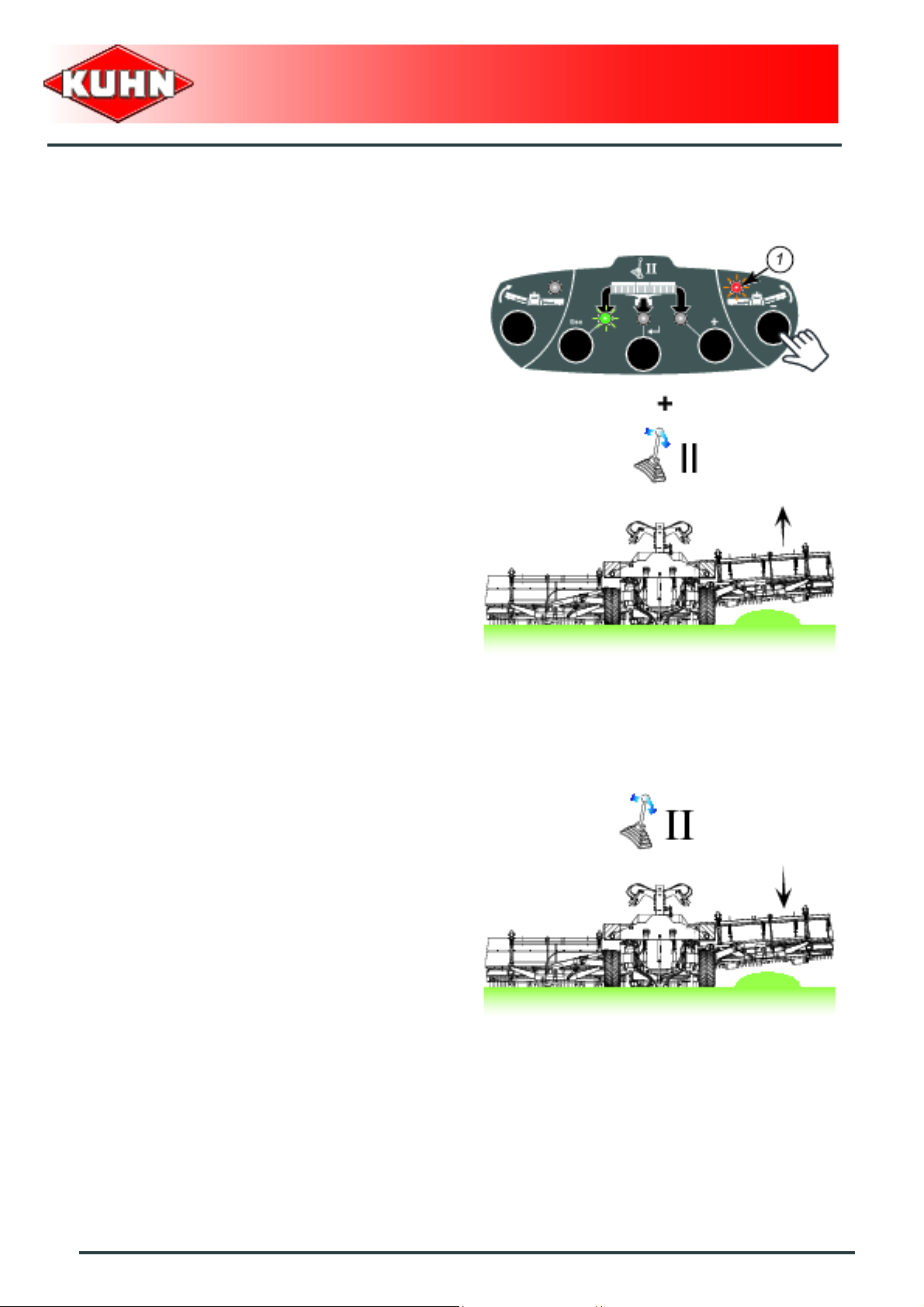
All pick-ups:
Putting the machine in headland turn position:
If one of the "putting the machine in headland turn
position" function has been activated previously
(Example: Right pick-up):
- Press concerned pick-up selection key to deactivate
the function.
• Indicator light (1) is OFF.
Merger
Merge Maxx 900
- Operate tractor hydraulic valve II in the headland turn
position direction:
• All the pick-ups are raised.
The central pick-up stops in the intermediate
position.
Operated hydraulic valve during 5 seconds to
position the central pick-up in transport position.
Putting the machine into work position:
- Operate tractor hydraulic valve II in the working
position direction:
• All the pick-ups are lowered.
74
Instructions for work
Page 77
Viewing the position of the pick-ups
During work, the pick-up position can be viewed on the
screen.
- Shortly press navigation key.
• Symbols (1) and (2) indicate that the pick-ups are in
lower position.
• The symbol (3) indicates the pick-up is in raised
position.
When symbol (2) is steady, the central pick-up
can be controlled.
When symbol (2) flashes, the central pick-up is
no longer controlled.
When the machine functions in deteriorated
mode, all pick-ups appear in low position.
Deteriorated mode: See section: Use in
deteriorated mode.
Merger
Merge Maxx 900
- Press shortly on the navigation key to quit viewing th e
pick-up position and to return to the hour counter.
Instructions for work
75
Page 78
Use in deteriorated mode
This mode enables neutralizing the position sensors
when one of the sensors is faulty. This allows continuing
to work and to fold/unfold the machine.
In deteriorated mode, the time delay for
placing the central pick-up in headland turn
position is neutralized.
To access the deteriorated mode:
- Select transport mode.
• Indicator light (1) flashes.
- Simultaneously press keys + and - for approximately
5 seconds.
• The message "SEC. ON" is displayed.
Merger
Merge Maxx 900
- Press key - (1) to switch to the deteriorated mode.
• The message "SEC. OFF" is displayed.
or
- Press key + (2) to switch back to the normal use
mode.
• The message "SEC. ON" is displayed.
- Press on validation key (3) to save the modifications
and return to the transport mode.
Each time the control box is energized, the
machine automatically switches into normal use
mode (SEC. ON).
If necessary, re-parametize the machine in
deteriorated mode.
- Press "Esc" key (4) to quit without saving the
modifications and return to the transport mode.
76
Instructions for work
Page 79

Error messages
If an error code is displayed on the screen, contact your
Kuhn dealer.
Note the sofware versions of th e T15M and
M400 before contacting your Kuhn dealer.
Press "Esc" key to delete error code.
Merger
Merge Maxx 900
Instructions for work
77
Page 80

1. Wide wheels
Kit no. 1146870
Merger
Merge Maxx 900
$Optional equipment
Technical specifications
When fitting this equipment, following technical specifications are modified
Width in transport position 3.10 m (10’2’’)
Tyres 500/45-22.5 (14 PLY)
Tyre pressure 1.6 bar (23.20 psi)
In certain countries the machine excee ds the
maximum legal size to drive on public roads.
78
Optional equipment
Page 81

Before carrying out any maintenance or
repairs on the machine, switch off the tractor
engine, remove ignition key, wait until all
moving parts have come to a standstill and
remove PTO shaft.
1. Frequency chart
Merger
Merge Maxx 900
$Maintenance and storage
Maintenance intervals are indicated for
normal conditions of use.
Lubrication
Oil change:
- Drive oil tank
- Step-up gearbox
Grease:
first time
machine for the
Before using the
hours of use
After the first 10
hours of use
After the first 20
hours of use
After the first 100
Once per week
Every 50 hours
Every 200 hours
Every 2 years
3
3
- The steering
system
- The left arm pivot
points
- The right arm pivot
points
3
3
3
Maintenance and storage
79
Page 82

- The undercarriage
articulations
Oil:
first time
machine for the
Before using the
hours of use
After the first 10
hours of use
After the first 20
hours of use
After the first 100
Merge Maxx 900
Once per week
Every 50 hours
3
Merger
Every 200 hours
Every 2 years
- The coupling
yokes
- The parking stand
Maintenance
Check:
- The belt tension
- Step up gearbox
oil level
- Tank oil level
- Braking system
- Fixing elements
- Check transport
wheel bolts for
tightness
3
3
33
33
3
33
33
33 3
Replace:
- Hydraulic tank
filter cartridge
80
Maintenance and storage
333
Page 83

2. Lubrication
The pictorials show the points to be greased (Part
no. 09905400).
Clean grease nipples before greasing.
Lubricate with SHELL multi-purpose grease
grade NLGI 2.
Oil with SHELL SAE 90 gear oil.
PTO shaft
Merger
Merge Maxx 900
- Every 8 hours:
• The U-joints (1).
• constant velocity joint (4).
- Every 20 hours:
• The transmission tube (2).
- Every 40 hours:
• Guide rings (3).
Maintenance and storage
81
Page 84

Oil change:
Hydraulic tank
Before draining oil, operate the machine for a
few minutes so that the oil warms up.
The oil tank contains 200 L (53 US gal) of SHELL TELLUS 46 oil.
When draining and refilling, it is recommended to use either SHELL TELLUS 46 oil or a mineral base oil
with viscosity grade conform with ISO 46 standard category HM.
- Unscrew filler plug (5).
- Place a container of sufficient capacity under drain
plug (7).
- Remove drain plug (7).
- Allow oil to drain completely.
- Wait for dripping to stop.
- Clean and reinstall drain plug (7) and its washer (6).
Replace it if necessary. (Part no. 82102229).
- Loosen bolts (1).
- Remove cover (2), spring (3) and oil filter (4).
- Replace the oil filter (4) (Part no. A4079112).
- Reassemble all components.
- Pour the correct oil quantity and quality through the
opening of the filler plug.
- Reinstall filler plug (5).
Merger
Merge Maxx 900
82
Maintenance and storage
Page 85

Merge Maxx 900
Step-up gearbox
Before draining oil, operate the machine for a
few minutes so that the oil warms up.
The step-up gearbox is lubricated with 1.2 L (0.32 US gal) of SAE 80W90 oil.
When draining and refilling, it is recommended to use either a mineral base oil with viscosity grade SAE
80W90 and API grade GL5, or a synthetic base oil, type PAO (Poly-Alpha-Olefins) with a viscosity grade
equivalent to SAE 80W90.
From the working position:
- Adjust the height of the lift linkage until the ge arbox is
horizontal.
- Place a container of sufficient capacity under drain
plug (1).
- Remove drain plug (1) and its washer.
- Unscrew filler plug extension (2).
- Allow oil to drain completely.
- Wait for dripping to stop.
- Clean and reinstall drain plug (1) and its washer.
Replace if necessary (Part no. 82102229).
- Pour the correct oil quantity and quality through the
opening of the filler plug.
- Clean and tighten the filler plug extension (2).
Merger
Maintenance and storage
83
Page 86

Grease:
- The steering system.
Merger
Merge Maxx 900
84
Maintenance and storage
Page 87

- The left arm pivot points.
Merger
Merge Maxx 900
Maintenance and storage
85
Page 88

- The right arm pivot points.
Merger
Merge Maxx 900
86
Maintenance and storage
Page 89

- The undercarriage articulations.
Merger
Merge Maxx 900
Maintenance and storage
87
Page 90
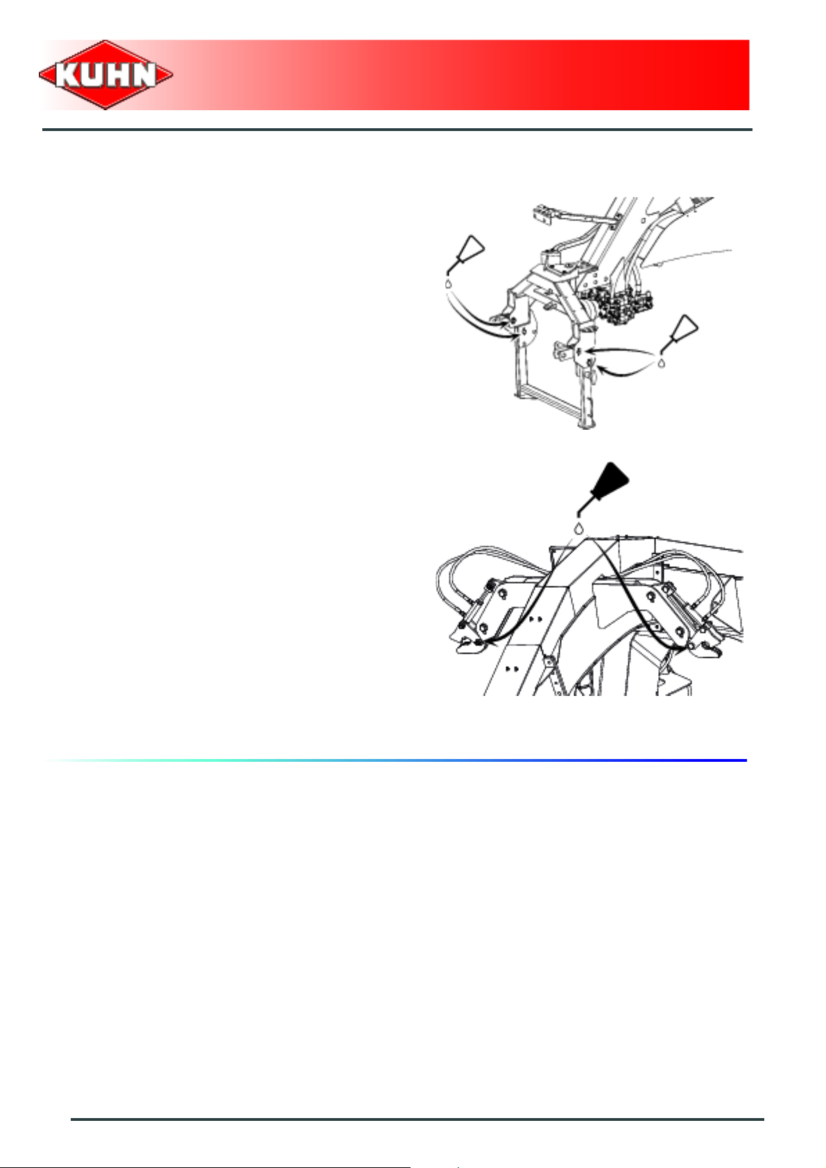
Oil:
- The coupling yokes.
- The parking stand.
Merger
Merge Maxx 900
- The transport locks.
88
Maintenance and storage
Page 91

3. Maintenance
Check:
The belt tension
Regularly check belt tension.
The conveyor belts stretch during their first hour s
of use.
Merger
Merge Maxx 900
Checking the central belt tension
- Measure distance (L):
If measure L is comprised between 1204 and 1208 mm
(3’11.40’’ - 3’11.56’’):
• The conveyor is tensioned.
If measure L is below 1204 mm (3’11.40’’):
• The conveyor belt is slack.
Factory supplied L = 1202 mm (3’11.32’’).
Check tension of the side conveyor belts
- Measure distance (L):
If measure L is comprised between 1505 and 1510 mm
(4’11.25’’ - 4’11.45’’):
• The conveyor is tensioned.
If measure L is below 1505 mm (4’11.25’’):
• The conveyor belt is slack.
Factory supplied L= 1502 mm (4’11.13’’)
Maintenance and storage
89
Page 92

Adjusting the tension:
- Unscrew the 2 nuts (1).
- Loosen the 2 screws (2).
Merger
Merge Maxx 900
1
2
1
- Remove bolt (1) and nut (2).
- Rotate pin (3) counterclockwise to tension the
conveyor.
- Rotate pin (3) clockwise to slacken the conveyor belt.
- Reinstall bolt (1) and nut (2).
- Tighten the 2 bolts (2).
- Tighten the 2 nuts (1).
1
2
1
90
Maintenance and storage
Page 93
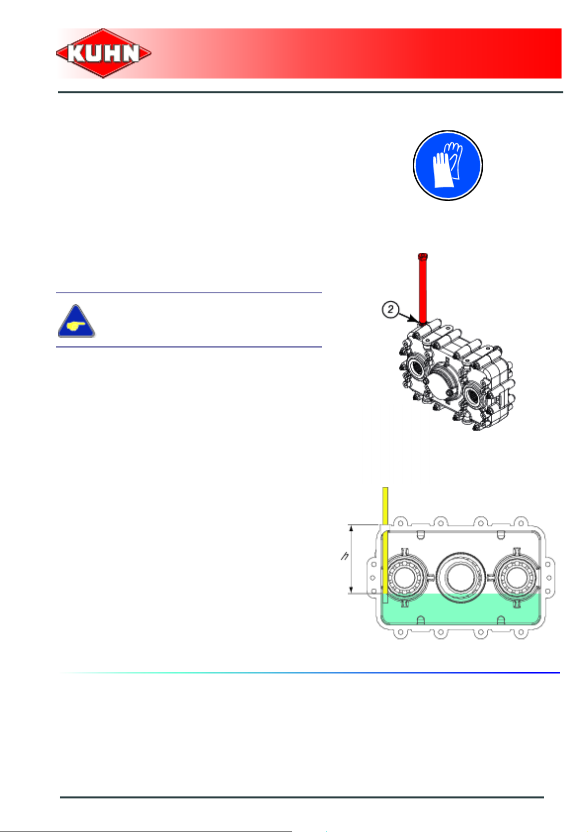
Step up gearbox oil level
Regurlarly check the step up gearbox oil level.
From the working position:
- Adjust the height of the lift linkage until the ge arbox is
horizontal.
- Unscrew filler plug extension (2).
- Through filling hole, check that oil height (h) is
comprised between 170 and 180 mm (6.7’’ - 7’’).
- Top up if necessary.
- Clean and tighten the filler plug extension (2). Replace
if necessary.
If in doubt as to the oil quantity contained in
the step up gearbox, fully drain and refill step
up gearbox respecting recommended oil
quantity and quality.
Merger
Merge Maxx 900
Maintenance and storage
91
Page 94
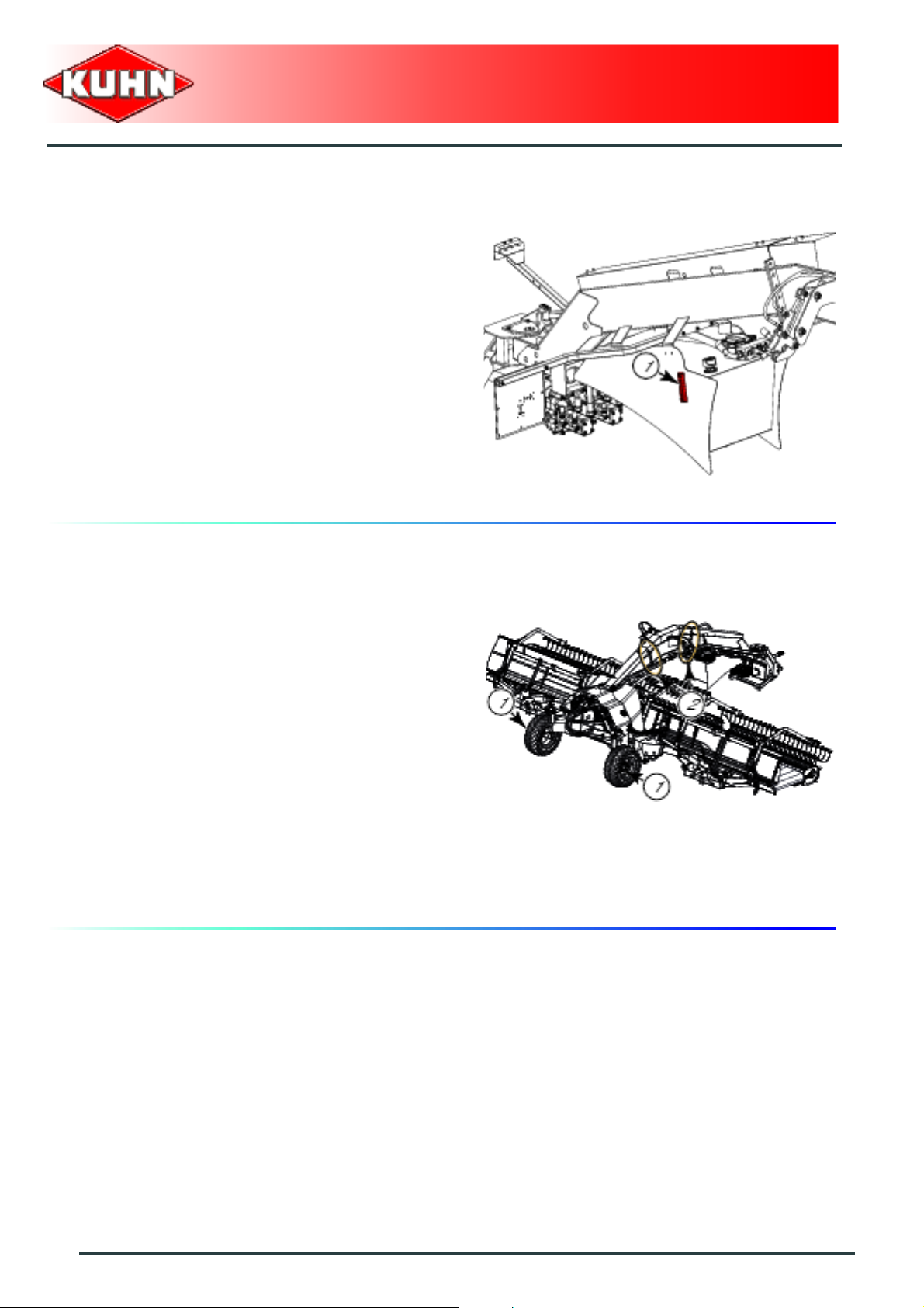
Tank oil level
- The oil level must reach the maximum mark on level
indicator (1) (in particular when working on slopes).
Merger
Merge Maxx 900
Fixing elements
Check transport wheel nuts (1) for tightness:
• Torque : 27 daN m (199 lbf ft).
Check the mounting screw tightness:
-Of frame (2).
• Torque : 28 daN m (206 lbf ft).
92
Maintenance and storage
Page 95

Braking system.
Check when it is cold. The machine is
coupled to the tractor.
- "Hydraulic" configuration.
Merger
Merge Maxx 900
- "Pneumatic" configuration.
Check piston travel of braking cylinders:
- Brake system not active.
• Measure dimension L.
- Activate brake system:
• Measure dimension L1.
Length L1 must not exceed measure L by more than 35
mm (1.38’’).
If the travel is greater than 40mm, contact
your Kuhn dealer to have the brake system
re-configured.
Maintenance and storage
93
Page 96

Tyre pressure
- Wide wheels (400/55 - 22.5 14 ply): 2 bar (29 psi).
- Wide wheels (500/45 - 22.5 14 ply): 1.6 bar (23 psi).
Merger
Merge Maxx 900
Emptying the air reservoir (depending
upon specification)
Before carrying out any maintenance or
repairs on the pneumatic braking system
circuit, apply machine brake and/or block
wheels using wheel chocks.
- Pull ring (1) to empty water contained in the air
reservoir.
Water in the circuit can cause malfunction of
the braking system.
94
Maintenance and storage
Page 97

Replace
Hydraulic tank filter cartridge
The "OIL FIL" message flashes when the
hydraulic tank filter is clogged.
Press "Esc" key (1) to delete message and to
return to the hour counter.
Merger
Merge Maxx 900
- Loosen the 4 self-locking screws (1).
- Remove upper filter cover plate (2).
- Grab spring (3).
- Replace the oil filter (4). (Part no. A4079112).
- Reassemble all components.
Maintenance and storage
95
Page 98

4. Storage
At the end of each season:
- Clean the machine thoroughly.
- Lubricate the whole machine.
- Check tyre pressure:
• Transport wheels: 2 bar (29 psi).
- Touch up any areas of damaged paintwork.
- Check and replace worn or damaged to ols .
- Put the machine under cover in a dry place.
- Store control box in a dry place free of dust
At the start of each season:
Merger
Merge Maxx 900
- Re-read the operators' manual.
- Check tyre pressure:
• Transport wheels: 2 bar (29 psi).
- Check that all nuts and bolts are sufficiently tightened.
- Make sure that all protection devices are in place and
in good condition.
- Check that the brakes work correctly.
96
Maintenance and storage
Page 99

Merge Maxx 900
$Trouble shooting guide
Problem Cause Remedy
Pneumatic braking system
Water in the circuit. Empty the circuit.
Malfunction of the
pneumatic
braking system.
Air leak.
Incorrect air pressure in the air
reservoir.
Incorrect air pressure in the brake
cylinders.
T15M control box
No display
E--0003
E--0010 Major fault. Contact your Kuhn authorized dealer.
E--0032
E--0033 Major fault. Contact your Kuhn authorized dealer.
E--0034 Major fault. Contact your Kuhn authorized dealer.
E--00b0 Major fault. Conta ct your Kuhn au thor ize d deale r.
E--0109
E--0110
No display when switching on by
pressing M/A.
Short circuit on the M400 module
power supply when switching on the
control box.
A control key is in contact when
switching the control box on.
Brief display when switching on.
T15M Control box voltage below 9 V.
T15M Control box voltage below 10
V.
Check condition and sealing of the
circuit components.
Contact your Kuhn dealer to service
and repair the brake system.
Check connection of the 3-pin plug.
Check condition of the battery power
cable.
Charge the battery.
If the problem persists, call your Kuhn
dealer.
Contact your Kuhn authorized dealer.
Check that a control key is not in
contact during switching on.
Keyboard fault.
If the problem persists, call your Kuhn
dealer.
Charge the battery.
Check cleanliness and connection of
the terminals on the battery.
If the problem persists, call your Kuhn
dealer.
Charge the battery.
Check cleanliness and connection of
the terminals on the battery.
If the problem persists, call your Kuhn
dealer.
Merger
Trouble shooting guide
97
Page 100

Merger
Merge Maxx 900
Problem Cause Remedy
Check tractor electric circuit.
E--0111
E--0112
E--1401 M400 module voltage is below 9 volts.
E--1402
E--1405 Solenoid valve voltage is below 9 V.
E--1406 Solenoid valve voltage is below 10 V.
E--1407
E--1408
E--1409 M400 module voltage is below 4.5 V. Contact your Kuhn authorized dealer.
T15M control box voltage exceeds 16
V.
T15M control box voltage exceeds
15.5 V.
M400 module voltage is below 10 V.
Brief display when switching on.
M400 module voltage exceeds 16 V.
M400 module voltage exceeds 15.5
V.
Check functioning of the generator
control unit.
If the problem persists, call your Kuhn
dealer.
Check tractor electric circuit.
Check functioning of the generator
control unit.
If the problem persists, call your Kuhn
dealer.
Charge the battery.
Check cleanliness and connection of
the terminals on the battery.
If the problem persists, call your Kuhn
dealer.
Charge the battery.
Check cleanliness and connection of
the terminals on the battery.
If the problem persists, call your Kuhn
dealer.
Check connection of the 3-pin plug.
Check condition of the battery power
cable.
Charge the battery.
If the problem persists, call your Kuhn
dealer.
Check connection of the 3-pin plug.
Check condition of the battery power
cable.
Charge the battery.
If the problem persists, call your Kuhn
dealer.
Check tractor electric circuit.
Check functioning of the generator
control unit.
If the problem persists, call your Kuhn
dealer.
Check tractor electric circuit.
Check functioning of the generator
control unit.
If the problem persists, call your Kuhn
dealer.
98
Trouble shooting guide
 Loading...