

Page 1
OPERATOR’S MANUAL
FERTILISER SPREADER
MDS 55 - 65 - 85 - 735 - 935
N° 95743 A.GB - 07.2003
Page 2
Introduction
Dear Customer,
By purchasing this precision fertiliser spreader you have shown confidence in our products that we are convinced will be justified through its performance and reliability. Thank you. We have made every effort to
provide you with a high performance machine but should any problems occur our service personnel are on
call at all times.
It is very important that you read and thoroughly understand this Operator Manual, taking careful note of the Safety Information, BEFORE operating the machine. This manual provides a comprehensive
guide to the machine controls and all the information necessary for efficient and safe operation, maintenance
and care of your machine.
PLEASE NOTE: Warranty claims which arise from damage due to operator errors and misuse, cannot be
accepted.
NOTE: We recommend that you make a note of the machine model, serial number and construction year in
the spaces below. You will find this information on the serial number plate fixed to the frame of the machine.
Always quote this information when ordering spare parts, optional equipment and accessories, or when making any claims under warranty.
Model: Serial No.: Construction year:
Technical improvements
We are committed to a policy of constant improvement on all our products. We therefore reserve the
right to carry out, without prior notice, any improvements or changes which we feel will benefit our
products, without any obligation on our part to carry out such improvements or changes to machines which have already been sold.
If you have any questions about these, or any of our products, please do not hesitate to contact us.
With kind regards
KUHN FARM MACHNERY
Page 3

Contents
I
Contents
Introduction............................................................................................................................................ 2
Technical improvements ...................................................................................................................... 2
Contents .................................................................................................................................................. I
1 Explanation of warning and safety decals ............................................................................... 5
2 Correct use .................................................................................................................................. 6
2.1 Operational safety ......................................................................................................................... 7
2.2 No liability is accepted for crop, property or environmental damage ............................................ 7
2.3 Public road safety.......................................................................................................................... 8
2.4 Lighting (applicable for Germany)................................................................................................. 8
2.5 Towing of trailers........................................................................................................................... 9
3 Accident prevention and safety issues................................................................................... 10
3.1 General safety recommendations for the hydraulic system........................................................ 13
3.2 Warning and instruction decals ................................................................................................... 13
4 Machine specifications............................................................................................................. 16
4.1 Technical specifications MDS 55 / 65 / 85 / 735 / 935 ................................................................ 16
5 Preparation of the fertiliser spreader ...................................................................................... 17
5.1 Taking delivery of the fertiliser spreader ..................................................................................... 17
5.2 Assembly of the MDS 55-935 fertiliser spreader ........................................................................ 18
5.3 Assembly of the MDS 55 M / 65 M / 85 M / 735 M / 935 M fertiliser spreaders.......................... 18
5.4 Assembly of MDS 55 K / 55 R / 55 D / 65 K / 65 R / 65 D / 735 K / R / D / 935 K / R / D
fertiliser spreaders....................................................................................................................... 19
5.5 Assembling the hopper to the frame and fitting the agitator ....................................................... 20
5.6 Attaching to the tractor ................................................................................................................ 21
5.7 Fitting the pto shaft...................................................................................................................... 22
5.8 Fitting and connecting the hydraulic metering slide controls ...................................................... 24
5.8.1 Single acting hydraulic metering control for MDS 55 K / 65 K / 85 K / 735 K / 935 K ......... 24
5.8.2 Double acting hydraulic metering control for MDS 55 D / 65 D / 85 D / 735 D / 935 D........ 25
5.8.3 Single acting hydraulic metering control with double acting mechanism for MDS 55 R / 65
R / 85 R / 735 R / 935 R.............................................................................................................. 25
5.8.4 Fitting the single acting hydraulic metering slide control FHK 4
and the double acting
hydraulic metering slide control FHD 4
.................................................................................. 26
5.8.5 Position indicator function: (only for MDS K / R / D)............................................................. 28
6 Adjusting the fertiliser spreader.............................................................................................. 29
6.1 General........................................................................................................................................ 29
6.2 Attachment height ....................................................................................................................... 30
6.2.1 Attachment height for normal spreading ............................................................................... 30
6.2.2 Attachment height for late top dressing ................................................................................. 30
Page 4

Contents
II
6.3 Hopper capacity / Hopper extension sets ................................................................................... 31
6.3.1 Calculation of maximum loading ............................................................................................. 31
6.3.2 Hopper level scale..................................................................................................................... 31
6.4 Setting application rates on the MDS 55 M / MDS 65 M / MDS 85 M / 735 M / MDS 935 M .... 32
6.5 Setting application rates on the MDS 55 K / R / D MDS 65 K / R / D MDS 85 K / R / D MDS
735 K / R / D and MDS 935 K / R / D .......................................................................................... 33
6.6 Adjustment of the multi-disc spreading discs.............................................................................. 34
6.6.1 Principle of operation ............................................................................................................... 34
6.6.2 Adjusting the disc vanes .......................................................................................................... 35
6.6.3 Adjustment according to the spreading charts ..................................................................... 37
6.6.4 Setting disc vanes for fertilisers not listed in the spreading charts.................................... 39
6.6.5 DiS 39
6.6.6 PtK 39
6.7 One-sided spreading................................................................................................................... 44
6.7.1 One-sided spreading MDS 55 M / MDS 65 M / MDS 85 M / MDS 735 M / MDS 935 M .......... 44
6.7.2 One-sided spreading MDS 55 K / MDS 65 K / MDS 85 K / MDS 735 K / MDS 935 K ............ 44
6.7.3 One-sided spreading MDS 55 D / MDS 65 D / MDS 85 D / MDS 735 D / MDS 935 D ............ 44
6.7.4 One-sided spreading MDS 55 R / MDS 65 R / MDS 85 R / MDS 735 R / MDS 935 R ............ 44
6.8 Yield and environmental optimised border spreading................................................................. 44
6.8.1 Yield optimised border spreading in the first tramline ......................................................... 44
6.8.2 Environmental and yield border spreading using the border spreading limiter GSE 7
(optional equipment). Only one metering slide is opened.................................................... 45
6.8.3 Environmental and yield border spreading using the border spreading limiter TELIMAT
T1 (optional equipment) ........................................................................................................... 45
The Tellimat T1 is deployed from the first tramline (1/2 working width from the field edge)................. 45
6.9 Spreading on small field strips .................................................................................................... 45
7 Calibration check / Purging unused fertiliser ........................................................................ 45
7.1 Calculating the mean application rate......................................................................................... 45
7.2 The calibration check process..................................................................................................... 47
7.3 Purging unused fertiliser ............................................................................................................. 48
8 Service and maintenance ......................................................................................................... 50
8.1 Cleaning ...................................................................................................................................... 50
8.2 Lubrication................................................................................................................................... 50
8.2.1 Pto shaft ..................................................................................................................................... 50
8.2.2 Agitator shaft and agitator ....................................................................................................... 51
8.2.3 Metering slides, positioning levers, links and adjustment scale segment ......................... 51
8.2.4 Disc hubs ................................................................................................................................... 51
8.3 Gearbox oil level.......................................................................................................................... 51
8.4 Wearing parts .............................................................................................................................. 52
8.5 Checking and setting the metering slide balance and specially checking the metering slides for
seed and slug pellet spreading ................................................................................................... 52
8.5.1 Checking the metering slide .................................................................................................... 52
8.5.2 Rebalancing the metering slides MDS 55 M / MDS 65 M / MDS 85 M / 735 M / 935 M ....... 53
8.5.3 Rebalancing the metering slides MDS 55 K / R / D MDS 65 K / R / D MDS 85 K / R / D
MDS 735 K / R / D and MDS 935 K / R / D ............................................................................... 54
9 Changing the spreading discs................................................................................................. 55
Page 5

Contents
III
9.1 Spreading disc removal............................................................................................................... 55
9.2 Replacing the extension vanes ................................................................................................... 56
9.3 Replacing the main vane or the complete vane assembly ......................................................... 58
9.4 Replacing the MDS vane with an X-vane ................................................................................... 64
9.5 Refitting the spreading discs ....................................................................................................... 65
10 Valuable tips for precision spreading..................................................................................... 66
10.1 Spreading procedure on headlands ............................................................................................ 67
11 Fault diagnosis.......................................................................................................................... 68
11.1 Uneven spread pattern................................................................................................................ 68
11.2 Fault diagnoses for hydraulic metering controls ......................................................................... 68
11.3 Disc vane wear............................................................................................................................ 68
12 Optional equipment................................................................................................................... 69
12.1 Hopper extension sets ................................................................................................................ 69
12.2 Hopper cover............................................................................................................................... 69
12.3 Hopper sieve ............................................................................................................................... 69
12.4 RFZ 7M (all MDS fertiliser spreaders except MDS 55)............................................................... 69
12.5 Double acting mechanism........................................................................................................... 69
12.6 Tele-Space .................................................................................................................................. 69
12.7 Practical Test Kit PtK................................................................................................................... 69
12.8 Fertiliser identification system FiS............................................................................................... 69
12.9 Row spreading unit RV 2M for hopyards and orchards .............................................................. 70
12.10 Boundary spreading limiter GSE 7.............................................................................................. 70
12.11 Electronic remote control EF 24.................................................................................................. 70
12.12 Hydraulic remote control FHZ 10 ................................................................................................ 70
12.13 Lighting without warning shield BLO1 (for rear profile lighting security) for MDS 65 / MDS 85)
71
12.14 Lighting without warning shield BLO2 (for rear profile lighting security) ..................................... 71
12.15 Lighting with warning shield BLW 1 (for rear profile lighting security) for MDS 65 / MDS 85 ..... 71
12.16 Lighting with warning shield BLW 8 (for rear profile lighting security) ........................................ 71
12.17 TELIMAT T1 ................................................................................................................................ 71
12.18 Hydraulic metering slide control FHK 4....................................................................................... 71
12.19 Hydraulic metering slide control FHD 4....................................................................................... 71
12.20 Agitator for grass seeds RWK 7.................................................................................................. 71
12.21 Agitator RWK 15.......................................................................................................................... 71
13 Axle load calculation ................................................................................................................ 72
14 Warranty conditions.................................................................................................................. 75
Page 6

Page 7
Erreur ! Style non défini. Erreur ! Style non défini.
5
1 Explanation of warning and safety decals
The following table shows symbols and their levels of hazard classification.
A safety symbol appears in the manual when the safety of the operator, or any
other person, or the normal operation of the machine, could be in danger. It is
essential that all safety symbols, safety and accident prevention instructions,
are observed.
It is vital that all users have the opportunity to read and thoroughly understand
these instructions.
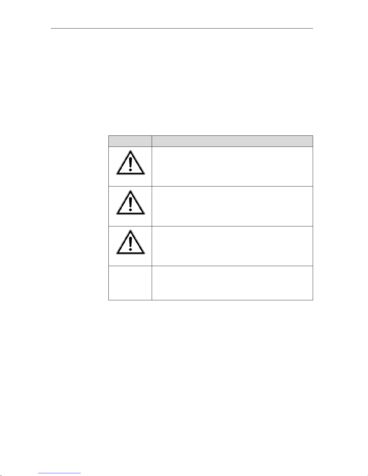
Symbol Classification
DANGER
DANGER !
Non observance can result in death or serious injury.
WARNING
WARNING !
Non observance can result in injury or damage to the machine.
IMPORTANT
IMPORTANT !
Non observance can result in damage to the machine or the
immediate environment.
ATTENTION
ATTENTION !
User tips for optimal implement operation and other useful information.
Page 8

Erreur ! Style non défini. Erreur ! Style non défini.
6
2 Correct use
The MDS fertiliser spreader is designed to spread dry, prilled and granular fertiliser, as well as seeds.
Any other use is inappropriate and any defects arising therefrom will invalidate
the manufacturer's warranty and relieve both manufacturer and supplier of any
liability.
Correct use also entails the full compliance with all operating, maintenance and
repair instructions issued by the manufacturer as well as the exclusive usage of
original spare parts.
KUHN original spare parts and accessories are especially designed and manufactured for fertiliser spreaders. Parts and accessories not supplied by KUHN
have not been subjected to our tests and quality control, essential to ensure
correct operation. KUHN is relieved of any liability for damage caused by the
use of non-original parts and/or accessories. The employment of non-original
parts and/or accessories can have a negative influence on the construction characteristics of the fertiliser spreader which could endanger the safety of both
people and the machine.
Any warranty or liability claims against the manufacturer for damage resulting
from unauthorised alterations to the fertiliser spreader will not be accepted.
The fertiliser spreader is built to current technical and accepted safety standards. However, potential risks of injury to the operator or to third parties, or
damage to the machine, or other property during operation, do exist. The fertiliser spreader is only in a correct technical condition, meeting accepted safety
and warning criteria, when all information and instructions in the operator manual are observed. Any faults which develop must be rectified immediately.
The MDS fertiliser spreader should only be used, maintained and repaired by
persons who are familiar with the machine and who have received instructions
with regard to potential dangers.
All current appropriate accident prevention requirements and all other general
recognised safey, technical work-related and road traffic legislation, must be
observed.
Page 9

Erreur ! Style non défini. Erreur ! Style non défini.
7
2.1 Operational safety
The MDS fertiliser spreader should only be put into operation after instructions
have been received from KUHN's business partners, employees and/or representatives, or KUHN's own personnel
Before starting up the machine, read the operator manual and carefully observe
all information and safety instructions.
Only start up the MDS fertiliser spreader when all protection and safety guards,
including any detachable protection devices, have been installed and are functioning correctly.
Check all nuts, bolts and locking elements regularly for correct tightness, and
tighten where necessary.
Regularly check all hydraulic hoses at the beginning of the season for mechanical defects (e.g. cuts, abrasions, crushed sections, kinks, tears, leaks, porosity,
etc.).
The useful life of an undamaged hose should be limited to six years, including a
possible maximum two-year stocking period. The manufacturing date of a
hydraulic hose is indicated on its outer surface in month and year.
If operational faults develop on the fertiliser spreader, stop immediately. Ensure
that the unit is safely parked and secured, rectify the problem. If the problem
cannot be safely rectified by the operator, have the matter rectified by trained
personnel.
2.2 No liability is accepted for crop, property or environmental damage
The MDS fertiliser spreader is carefully manufactured by KUHN. In spite of this,
even when correctly using the unit, variations in output or total output failure can
occur, for example:
• Variations in the physical characteristics of fertiliser and seed products (e.g.
variations in granule sizes, density, granule forms, surface, causticity, packaging and humidity).
• Blockage or bridging around hopper outlets caused by foreign particles,
contaminated seeds, sticky causticity, moist fertiliser, etc.).
• Component wear.
• Damage from outside influences.
• Incorrect operational speed or forward speed.
• Incorrect settings of the fertiliser spreader (i.e. incorrect metering slide
control setting, non-observance of spreading charts).
Before each field operation, as well as during operation, check that the fertiliser
spreader is functioning correctly and that the correct application rate and spread
pattern is being achieved at all times. No claims are accepted for any damages
other than on the fertiliser spreader itself. No liability can be accepted for
consequential loss or damage due to spreading errors.
Page 10

Erreur ! Style non défini. Erreur ! Style non défini.
8
2.3 Public road safety
When driving on public roads, or along tracks, or in public parks, observe all
traffic rules and regulations.
Make sure that the fertiliser spreader complies with all public traffic rules and
specifications.
Observe all maximum transport width laws and equip the unit with all correct
lighting and traffic warning shields.
Make sure tractor steering and braking efficiency is not impaired in any
way!
Due to the combined weight of the fertiliser spreader and material in the hopper,
it is possible that the tractor/fertiliser spreader combination could become
unstable.
Attaching units to either front or rear 3-point tractor linkages must not exceed
the maximum permissible total weight, individual permissible axle weight or maximum tyre loads. The front axle must be ballasted to achieve a minimum load
of 20% of total unloaded weight (see chapter 13: Axle Load Calculation).
• Ensure that all these conditions can be entirely met before the fertiliser
spreader is attached. Observe all instructions and recommendations relating to weight and axle loading, as given in the tractor operator manual.
• Steering characteristics can deteriorate when implements are attached.
• Be aware that implements need more room when driving through curves
due to their long overhang, and can negatively affect stability due to their
large mass.
DANGER
Make sure tractor steering and braking efficiency is not impaired in
any way!
Steering and braking efficiency is influenced when attaching a fertiliser spreader
and its load. Ensure that steering and braking efficiency is correct and reduce
forward speed to suit load conditions!
2.4 Lighting (applicable for Germany)
General
If part of the tractor lighting system or official number plate is obscured, it is necessary to equip the spreader with an auxilliary system, even if only operated in
daylight hours.
Attachment height
When driving on public roads running lights must not exceed a height of
1500mm and reflectors a height of 900mm, above ground level.
Rear warning shield requirements
If the fertiliser spreader extends more than 1000mm beyond the tractor running
lights, a rear warning shield is required.
DANGER
Page 11

Erreur ! Style non défini. Erreur ! Style non défini.
9
Front and rear warning shield requirements
If the fertiliser spreader protrudes more than 400mm from the tractor's outermost light position, the outermost body area or its running light, additional running lights and warning shields must be positioned on the outermost point of the
fertiliser spreader, facing both forwards and rearwards.
Night or poor light conditions
If transporting at night or in poor light conditions, additional lighting is required in
both the forward and rear facing positions.
For lighting requirements in other countries
The fertiliser spreader's lighting and warning system must conform to local public highway traffic regulations. Check with your local authorities and your dealer
that the unit conforms to all regulations.
2.5 Towing of trailers
Note the following :
• When towing trailers, 25 kph must not be exceeded.
• The trailer must be equipped with a hand brake or a braking system that
can be operated by the driver from the tractor cab.
• The total loaded weight of rigid drawbar trailers must not exceed the weight
of the pulling vehicle, and jockey wheels, if used to support the drawbar
weight, should transmit the load to the ground in such a way that the pulling
vehicle can safely steer and brake.
• Articulated drawbar trailers can only be used when the actual total loaded
weight of the trailer does not exceed 1.25 times the weight of the pulling
vehicle. However, the total weight should not exceed 5 tonnes.
Page 12

Erreur ! Style non défini. Erreur ! Style non défini.
10
3 Accident prevention and safety issues
Most accidents happen because someone ignores the most elementary safety
rules during operation, maintenance or transport. It is vital that all persons coming in contact with the machine - the purchaser himself/herself, a member of
his/her family, an employee, a bystander - strictly obey the following safety rules. Other safety instructions are to be found on the decals placed in various
prominent positions on the machine. The machine should only be set up for
operation, operated and maintained by persons who have received instructions
with regard to potential dangers.
• Observe all safety notes contained in this operator manual and all current
statutory safety and accident prevention regulations!
• Warning and instruction decals give important information to operate the
fertiliser spreader without danger and to serve to increase the safety of the
operator.
• Before every operation, check nuts and bolts and other fixings for tightness,
especially those of the spreading discs and spreading vanes. If necessary,
tighten to recommended torque settings.
• Before using the machine, operators must familiarise themselves with all
parts of the equipment and the function of all controls and adjustments.
Finding out during operation may be too late.
• Before every operation, ensure that the tractor/spreader combination
complies with all relevant road traffic, as well as health and safety, regulations.
• When filling the hopper, lower the spreader and switch off the tractor engi-
ne. Remove ignition key before leaving the tractor cab. Make sure metering and shutter slide controls are closed.
• Before adjusting or undertaking other work such as cleaning, lubricating or
carrying out operations on the spreader, disengage the pto drive, switch off
the tractor engine, wait until all moving parts have come to a stop and remove the ignition key. During control or repair work, make sure no one can
start the unit by mistake.
Crushing hazard from power driven parts!
Rotating machine elements (discs, agitator, pto shaft) can cause serious injury
or death.
• Only start the machine when the hopper sieve, disc guards, pto shrouds
and all other guards, are in place!
• Always avoid wearing loose clothing or clothing with loose parts that are li-
able to come into contact with moving parts.
• Avoid wearing clothes with belts, fringes or other items that could get
caught up in moving parts.
• Never get close to revolving parts. Keep hands, feet and clothing well away.
• Never reach into the hopper or touch the rotating discs.
• Never climb onto the spreader when it is operating.
• Keep the hopper free of any foreign objects (e.g. nuts or bolts).
DANGER
Page 13

Erreur ! Style non défini. Erreur ! Style non défini.
11
• Before starting the spreader, make sure that there is no-one within the dan-
ger area around the machine. Make sure you have a good view all round
and keep a special watch out for children!
• Only start up the spreader when all safety devices and guards have been
properly fitted (e.g. pto guards and disc shrouds).
Danger from fast moving spreading material!
Fast moving spreading material can lead to serious injury (e.g. eye injuries).
• Before engaging the pto drive/spreading discs, make sure no-one is within
the spreading zone around the spreader!
• Never leave the spreader running unattended.
• It is illegal and dangerous to carry passengers when using or transporting
the spreader.
• Do not use any parts of the fertiliser spreader as a step (e.g. disc, rear rail
guard).
• Before leaving the tractor seat, lower the spreader to the ground, switch the
tractor off and remove the ignition key. With single acting hydraulic shutter
operations, close the hydraulic shut-off valve.
• Parking the fertiliser spreader when it is not attached to the tractor: only with
an empty hopper and on firm, level ground.
• Never allow anyone to enter the space between the tractor and spreader
without first making sure that the tractor is prevented from moving by means
of a parking brake and/or wheel chocks!
• Before attaching or removing the spreader from the tractor 3-point linkage,
make sure that the operating system is positioned so that inadvertent lowering or raising of the linkage is impossible.
• It is recommended that the condition of the spreader is checked by a re-
commended dealer at the end of every season. Especially disc vanes, fixings and hydraulic parts.
• In the event of a failure during operation, switch off the spreader immediate-
ly. Stop engine and remove the ignition key before checking and repairing
the damage.
• Ill advised choice or use of fertiliser or other spreading material can cause
serious damage to people, animals, plants and the environment. Choose
the correct material for your application. Handle with care and carefully follow the manufacturer's instructions. Wear protective clothes and a protective breathing mask.
• Respect all recommended service periods as well as any inspection or test
recommendations to be carried out from time to time, which are given in
the operator manual.
• Before any cleaning, servicing or repair work, relieve all hydraulic pressure,
disengage the pto drive, switch off the engine and remove the ignition key.
Detach unit from the tractor.
• Only commence cleaning, servicing or repair work when the unit is on firm
level ground and is prevented from moving or jack-knifing (parking
legs/rollers).
WARNING
Page 14
Erreur ! Style non défini. Erreur ! Style non défini.
12
• Any pto damage should be repaired immediately before continuing sprea-
ding operations.
• Do not operate the machine with unguarded pto components. Only start up
the unit when all guards are correctly in place and functioning.
• Before cleaning the fertiliser spreader with a high pressure water or steam
jet, or any other cleaning material, make sure all openings or areas, that for
safety or operational reasons should not come into contact with water or other cleaning materials, are sealed off and adequately protected. For example: electrical elements or exposed bearings. After cleaning, make sure any temporary protection covers are removed.
• After cleaning, check all hydraulic hoses for leaks, loose connections, cuts
and other damage. Any damage should be repaired immediately!
• Disconnect the current supply before working on any electrical installations.
• Disconnect tractor battery cables before undertaking any welding operati-
ons on the fertiliser spreader.
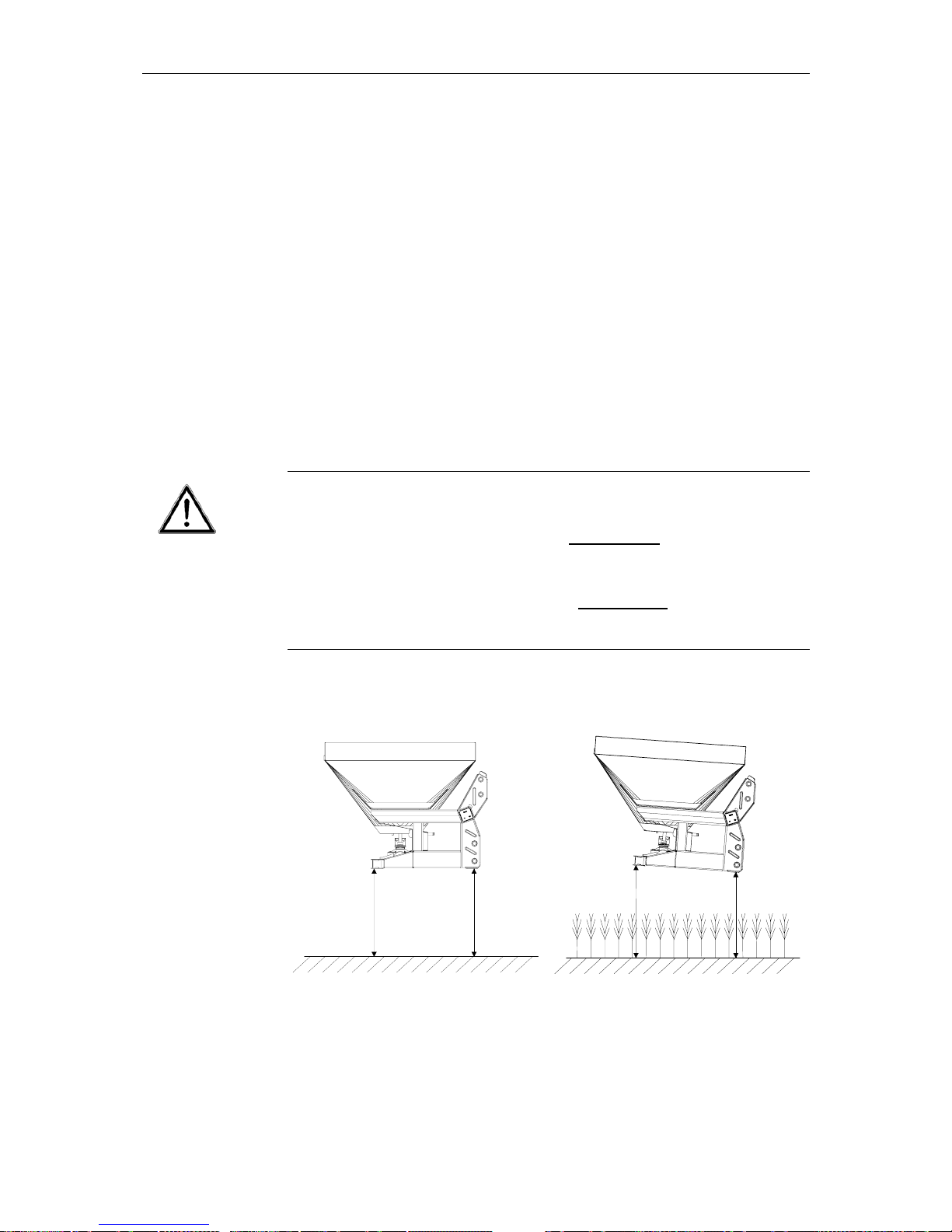
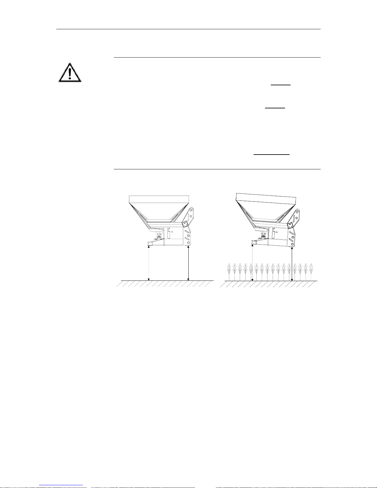
Maximum attachment height of the fertiliser spreader
Danger of injury by unintentional contact with the spreading discs.
• The maximum allowable distance from ground level
to the underside of
the frame when the unit is operating in normal spreading mode : must not
exceed 85 cm at point A and 85 cm at point B.
• The maximum allowable distance from ground level
to the underside of
the frame when the unit is operating in late top dressing mode must not
exceed 77 cm at point A and 83 cm at point B.
IMPORTANT
B
(85 cm)
A
(85 cm)
B
(83 cm)
A
(
77 cm
)
Ground level Ground level
Max. allowable attachment
height in normal spreading
mode
Max. allowable attachment
height in late top dressing
Page 15

Erreur ! Style non défini. Erreur ! Style non défini.
13
3.1 General safety recommendations for the hydraulic system
• Hydraulic circuits contain oil under high pressure.
• The maximum operating pressure (tractor hydraulic system) should not ex-
ceed 200 bar.
• Pay attention to specified hydraulic hose connections when connecting
hydraulic cylinders and hydraulic motors.
• When connecting up the hydraulic hoses to the tractor hydraulics, make su-
re that all hydraulic pressure has been relieved from both the tractor and the
fertiliser spreader.
• All male and female connections should be correctly labelled to eliminate
any possibility of incorrect operation when connecting various hydraulic operating elements between the tractor and fertiliser spreader.
• Regularly check all hydraulic hoses for signs of damage and age, and
replace if in any doubt. Replacement hoses must meet the manufacturers'
technical specifications.
• Even when carefully stored and correctly used, hoses and hose connecti-
ons undergo a natural aging process. Therefore, their stocking and operational periods should not be exceeded.
• The useful life of an undamaged hydraulic hose should be limited to 6
years, including a possible maximum two-year stocking period.
• The hydraulic hose manufacturing date is indicated on the hose with the
month and year of manufacture (e.g. SLP 8 / 00).
• Use suitable protection (gloves and protective eye-glasses, etc.) when loca-
ting oil leaks, in order to avoid injury.
• Hydraulic fluid escaping under high pressure can penetrate the skin and
cause serious injuries. In case of injury, immediately consult a doctor, as
there is a high risk of infection!
• Before carrying out any service or maintenance work on the hydraulic sys-
tem, lower the fertiliser spreader to the ground, relieve the system of pressure, switch off the engine and remove the ignition key.
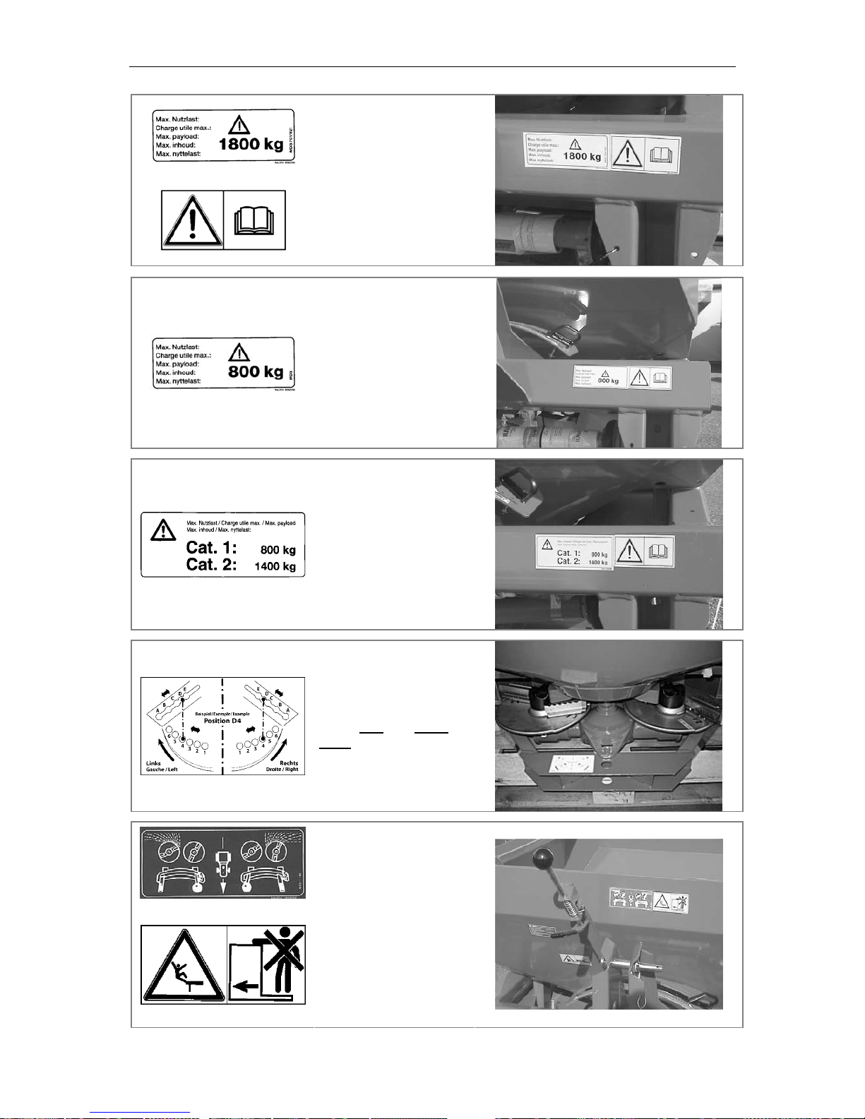
3.2 Warning and instruction decals
Warning and instruction decals give important information to operate the MDS
fertiliser spreader without danger.
Warning decals are situated at various points on the fertiliser spreader and give
important information for your safety and the safety of others. They also contain
information on correct operation. The text on each decal explains the message
that the symbol is giving.
• Replace any decal as soon as it is damaged or unreadable.
• Replacement decals can be obtained from the spare parts service dept.
• Before placing the new decal on the machine, make sure the surface is free
from dust, dirt and oil, and is totally dry.
• Make sure that any new part or component is correctly equipped with any
corresponding warning decal.
Page 16
Erreur ! Style non défini. Erreur ! Style non défini.
14
Maximum payload for
MDS 735 - 935.
Before starting up the
machine, read the operator manual and safety
instructions carefully.
Maximum payload for
MDS 55.
Maximum payload for
MDS 65 and MDS 85 :
Cat I : 800 kg
Cat II : 1400 kg
Disc vane adjustment
of the left-
and right-
hand spreading discs.
One-sided spreading.
It is not permitted, and
also very dangerous, to
carry persons on the
fertiliser spreader, or
be accompanied by any
persons while the machine is in operation.
Page 17
Erreur ! Style non défini. Erreur ! Style non défini.
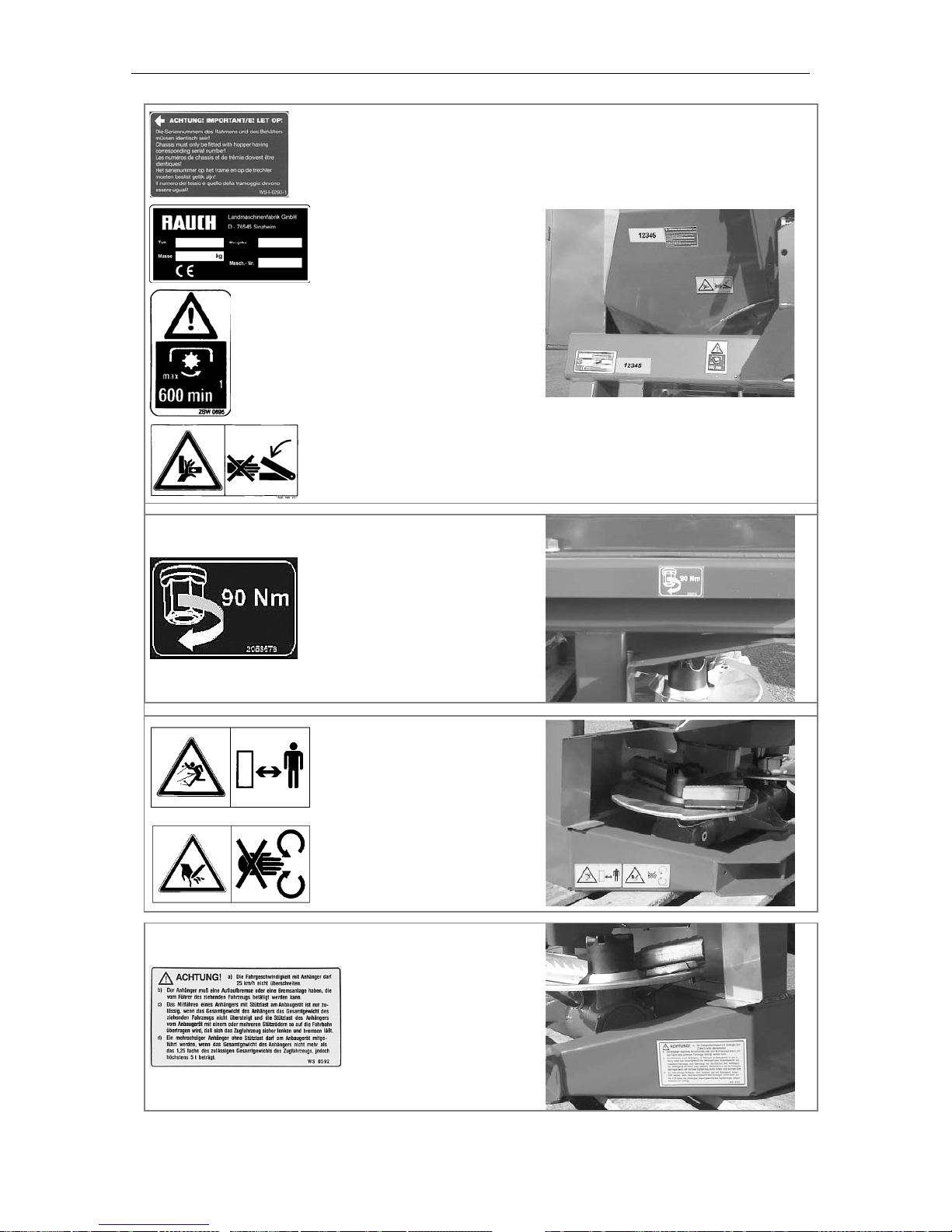
15
Serial number on frame
and hopper must be identical.
Serial number plate.
Pto speed.
Crushing and amputation hazard in region of
adjustment segments.
Torque setting
hopper to frame attachment.
Danger from fast moving spreading material. Make sure no-one is
within the spreading
zone before engaging
spreading discs!
Never reach into the
spreading disc or agitator zone.
Towing trailers behind
the implement (only for
Germany).
Page 18
Erreur ! Style non défini. Erreur ! Style non défini.
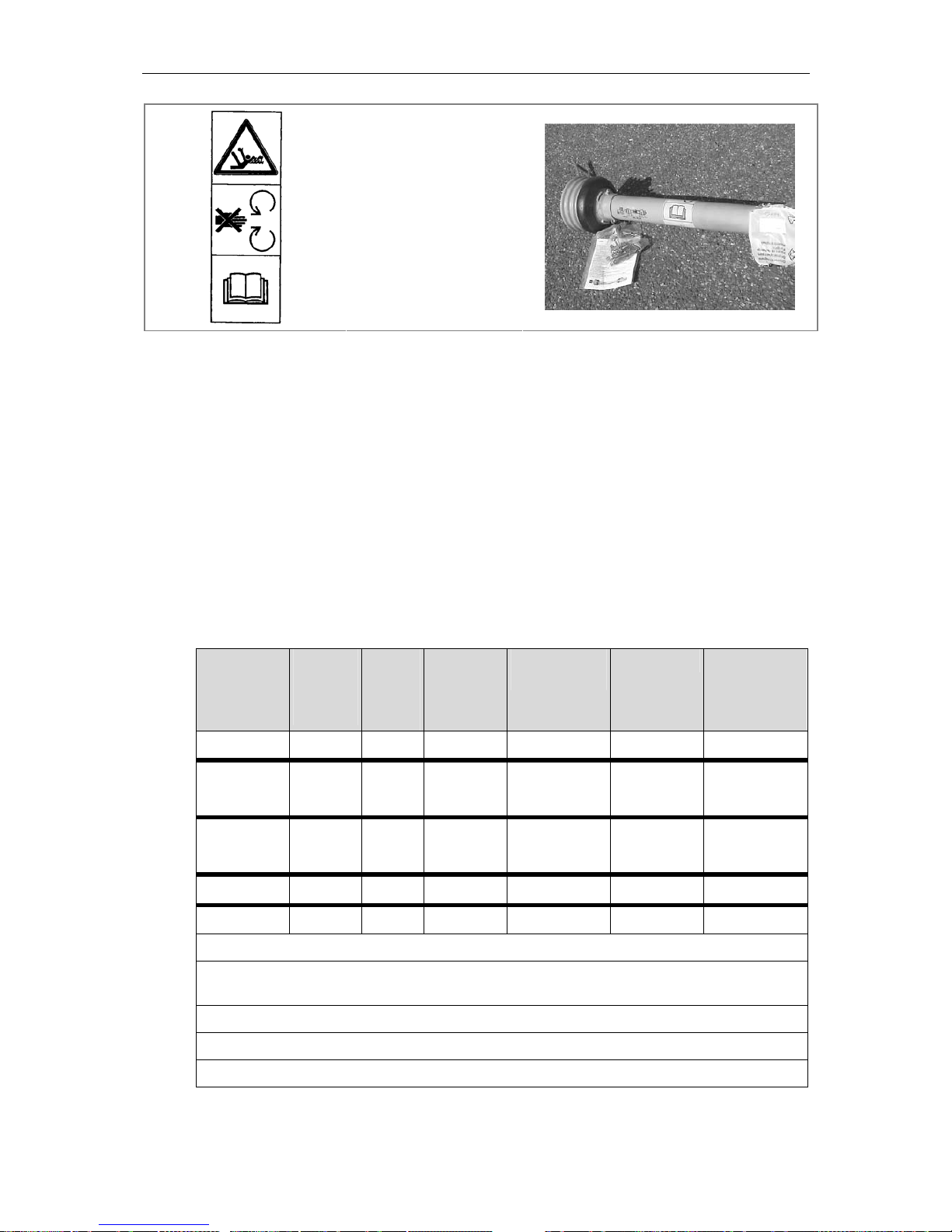
16
Do not stand near rotating elements.
This is a hazard which
can cause serious injury or death!
Observe all instructions in the pto manufacturers' operator manual!
4 Machine specifications
Manufacturer
RAUCH Landmaschinenfabrik GmbH
Landstraße 14 Postfach 1165
D-76547 Sinzheim D-76545 Sinzheim
Tel.: +49-7221 / 985-0 Fax: +49-7221 / 985-200
Service Centre: Tel.: +49-7221 / 985-250 Fax: +49-7221 / 985-203
4.1 Technical specifications MDS 55 / 65 / 85 / 735 / 935
Model Hopper
size
approx.
cm
Filling
height
approx.
cm
Filling width
approx. cm
Hopper capacity
approx. litres
Payload Kg Empty weight
approx. Kg
MDS 55 108x108
92 98 500 800 200
MDS 65
140x115
92 130 600
800 (Cat I)
1400 (Cat II)
210
MDS 85
140x115
104 130 800
800 (Cat I)
1400 (Cat II)
220
MDS 735 190x120
93 180 700 1800 250
MDS 935 190x120 101
180 900 1800 250
Centre of gravity distance from the lower linkage point is 55 cm with the hopper empty
Working width, depending on fertiliser type and spreading discs employed, is between 10m and 18m
(24m)
Maximum hydraulic pressure 200 bar
Pto speed 540 rpm
Noise level: 78 dB (A) measured with the tractor cab closed
Page 19

Erreur ! Style non défini. Erreur ! Style non défini.
17
Empty weight data is given on the fertiliser spreader serial number plate.
The weight of the fertiliser spreader when empty, varies according to equipment
fitted. The weight indicated on the serial number plate applies to the most
commonly used specification. It can, however, be higher or lower.
Hopper extension kit for MDS
65 / 85
Hopper size
approx. cm
Filling
height
approx. cm
Filing
width
approx.
cm
Additional
hopper capacity approx. litres
Extension
kit weight
approx.
Kg
M 20
140x115 +12,5 130 +200 +19
M 40
140x115 +24,5 130 +400 +28
Hopper extension kit for MDS
735 / 935
Hopper size
approx. cm
Filling
height
approx. cm
Filling
width
approx.
cm
Additional
hopper capacity approx. litres
Extension
kit weight
approx.
Kg
M 223
190x120 + 0 180 + 200 + 20
M 420
190x120 + 18 180 + 400 + 30
M 423
190x120 + 8,5 180 + 400 + 30
M 650
190x120 + 30 180 + 600 + 40
M 653
240x120 + 16 230 + 600 + 40
M 863
240x120 + 26 230 + 850 + 50
5 Preparation of the fertiliser spreader
5.1 Taking delivery of the fertiliser spreader
When the fertiliser spreader is delivered, please check that it is complete.
The following items are included as standard equipment:
• Operator manual / spreading charts
• Calibration kit
• Agitator
• Top and bottom 3-point linkage pins
• Set of spreading discs with adjusting lever
• Pto shaft, including pto instruction book
Also carefully check all ordered optional equipment
IMPORTANT
Check all nuts and bolts
• Check all nuts and bolts and other fixings for tightness, especially those of the
spreading discs and spreading vanes!
Positioning of the spreading discs on their hubs
• When positioning the spreading discs on their hubs, do not invert the spreading
disc (L) and spreading disc (R)!
• Place the spreading discs carefully onto their hubs with the right-hand disc (R)
on the right-hand side and the left-hand disc (L) on the left-hand side, when
viewed in direction of travel.
ATTENTION
Page 20
Erreur ! Style non défini. Erreur ! Style non défini.
18
Check for any transport damage or any missing parts. Claims can only be accepted if notification is made at time of delivery. Ask the haulier to acknowledge
any transport damage. In case of doubt, contact your dealer or the manufacturer direct.
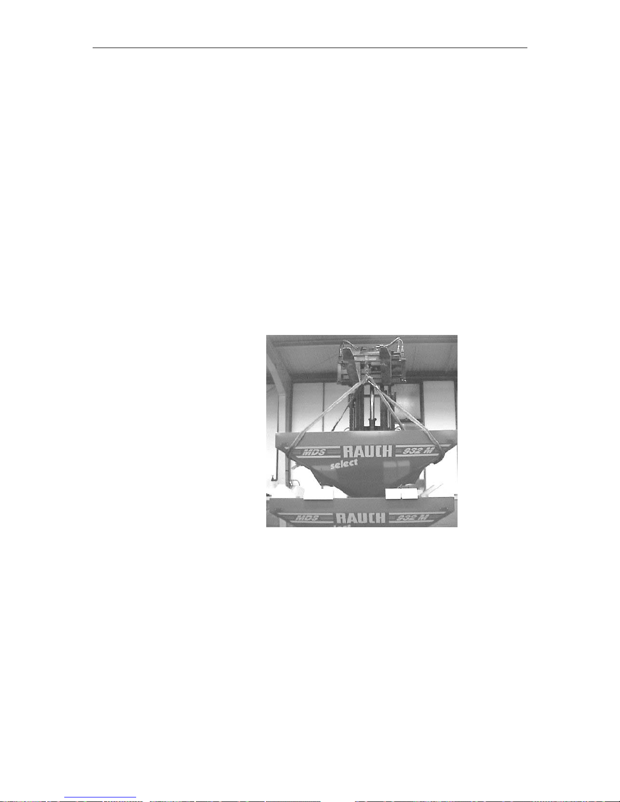
5.2 Assembly of the MDS 55-935 fertiliser spreader
To reduce the transport volume, hopper and carrying frames are packed separately.
Use a fork-lift truck or front-end loader with suitable slings to unload the hopper
(see photo below).
Likewise, use a fork-lift truck or front-end loader with suitable slings to unload
the frame.
Both hopper and frame have a serial number printed on the right-hand side,
when viewed in the direction of travel. Numbers on both the frame and hopper
must be matched when assembling (see photo, section 3.2).
5.3 Assembly of the MDS 55 M / 65 M /
85 M / 735 M / 935 M fertiliser spreaders
Close the metering slide and place the hopper carefully on the frame. Bolt the
frame and hopper together (see photos 1 and 2, section 5.5).
Page 21
Erreur ! Style non défini. Erreur ! Style non défini.
19
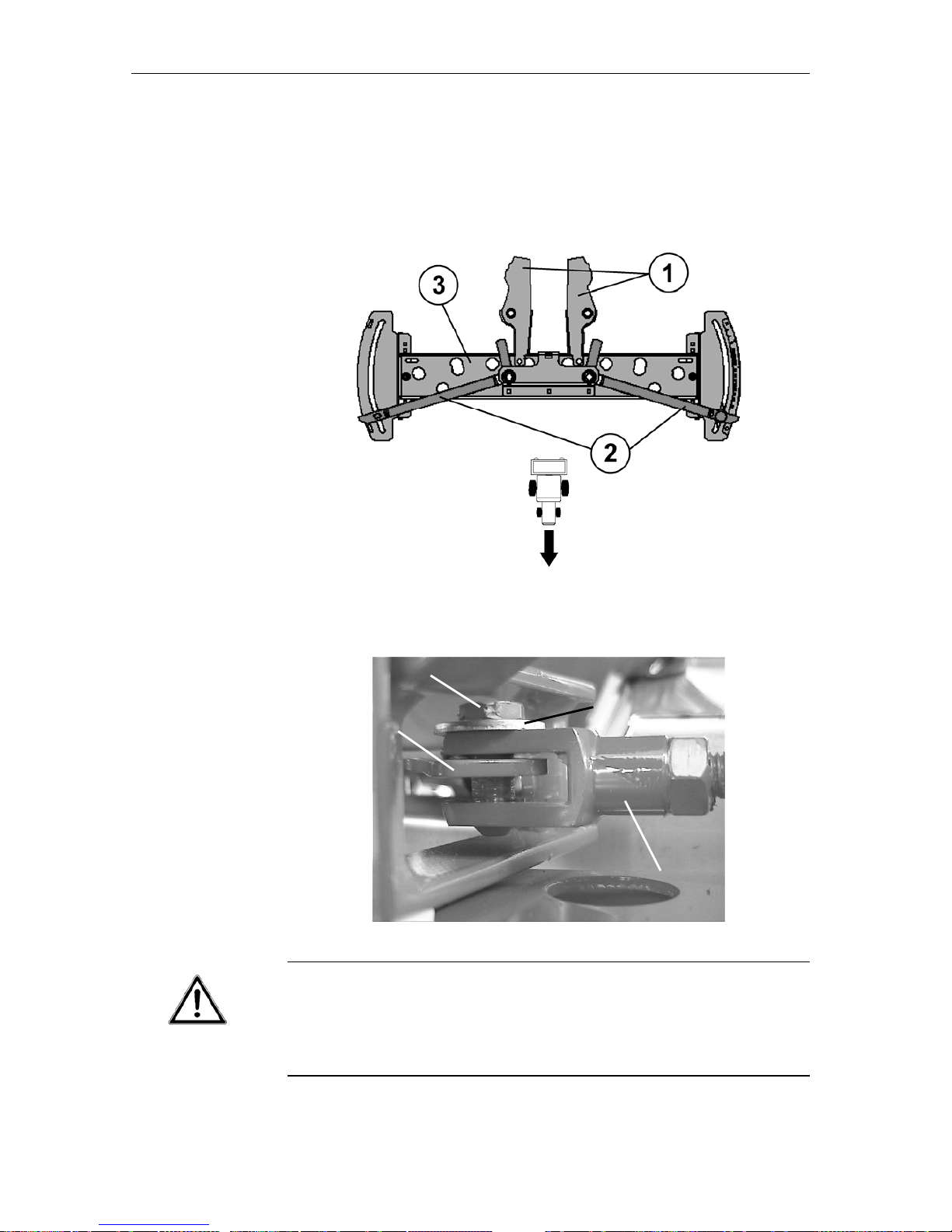
5.4 Assembly of MDS 55 K / 55 R / 55 D / 65 K / 65 R / 65 D /
735 K / R / D / 935 K / R / D fertiliser spreaders
Manually position both metering slides (1) parallel to the direction of travel. Place both left- and right-hand side positioning levers (2) into the highest position
(550). Position both hydraulic cylinders attached to the bridge frame (3) in the
direction of travel.
Connect the metering slides (8) to the hydraulic piston fork yokes (9) using retaining washers (11) and retaining pins (10).
Danger of crushing from machine components!
By unintentional operation of the control valve or shut-off valve, the open metering slides could close leading to crushing or amputation injuries.
• Before any assembly or adjustment, close the metering slides and close the
hydraulic shut-off valve.
WARNING
9
10
11
8
Page 22
Erreur ! Style non défini. Erreur ! Style non défini.
20
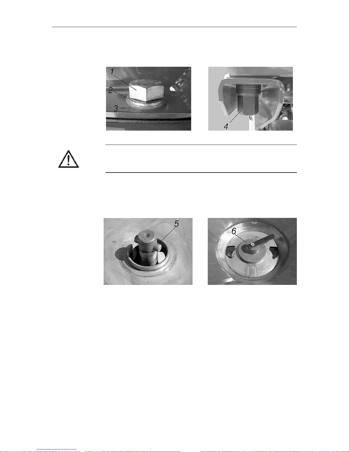
5.5 Assembling the hopper to the frame and fitting the agitator
Photo 1 Photo 2
Torque setting
The thread of the synthetic nut can be damaged if overtightened.
• Bolt the hopper to the frame using a torque setting of 90 Nm.
Grease the agitator shaft (5) around the dowel pin with graphite grease (see
photo 3). Likewise, grease the agitator head bore (6) with graphite grease and
place over the shaft, ensure correct engagement by rotating (see photo 4).
Photo 3 Photo 4
1. M 20 bolt
2. Metal washer
3. Synthetic washer
4. Synthetic nut
IMPORTANT
Page 23

Erreur ! Style non défini. Erreur ! Style non défini.
21
5.6 Attaching to the tractor
3-point linkage
Respect correct attachment procedures when coupling the fertiliser spreader to
the tractor and only couple the unit to approved attachment elements.
Non-observance of the correct 3-point linkage category can lead to injury or
damage to the machine, as well as the environment.
• The 3-point linkage of the tractor and fertiliser spreader must be the same
category, or must be adapted to suit (contact your dealer, if in doubt).
• Make sure no-one is standing between the machine and the tractor when
backing the tractor up to the fertiliser spreader.
• If there is not enough free room between the fertiliser spreader and the trac-
tor to easily connect drive and control elements, it is recommended to fit a
telescopic (Tele-Space) pto drive shaft, available as optional equipment.
Payload
Non-respect of maximum payload can lead to injury or damage to the fertiliser
spreader as well as the surrounding environment.
• Pay careful attention to all payload information given in section 4 !
The fertiliser spreader is attached to the tractor 3-point linkage. Attachment to
Cat.III tractor linkages is only possible using Cat.III geometry and placing reduction sleeves over the upper and lower linkage pins. A second lower link connection is provided as standard and allows a higher attachment height on the
tractor of approx. 140mm.
3-point linkage positions
• If the lower link pins are in the upper connection point, then the top link pin
must also be placed in its upper connection point, to avoid poor load distribution between upper and lower links.
• Both lower and top link pins must be secured in place with the linchpin provided!
For correct horizontal spreading of fertiliser, the fertiliser spreader must be attached to the tractor, according to the dimensions given in the calibration charts.
Pay attention that the spreader is mounted at right-angles to the direction of travel, is perfectly horizontal and that the 3-point frame is correctly restrained from
sideways movement to avoid the unit swinging from side to side during operation.
ATTENTION
If there is not enough free room between the tractor and spreader to easily connect the drive or control elements, an extendable Tele-space pto shaft can be
supplied as optional equipment to facilitate extra working space.
For safety and comfort reasons, the use of lower linkage pick-up hooks in connection with a hydraulic top link is highly recommended.
IMPORTANT
IMPORTANT
IMPORTANT
Page 24
Erreur ! Style non défini. Erreur ! Style non défini.
22
5.7 Fitting the pto shaft
Only pto shafts supplied or recommended by the manufacturer should be used.
When first attaching the spreader to the tractor, the length of the shaft must be
matched to the tractor. Read the pto manufacturer's operator manual care-
fully, taking special note of the instructions concerning the shortening of
the shaft. This operator manual is found attached to the pto shaft. If the shaft
is too long, both pto drive and spreader may be damaged when the unit is raised.
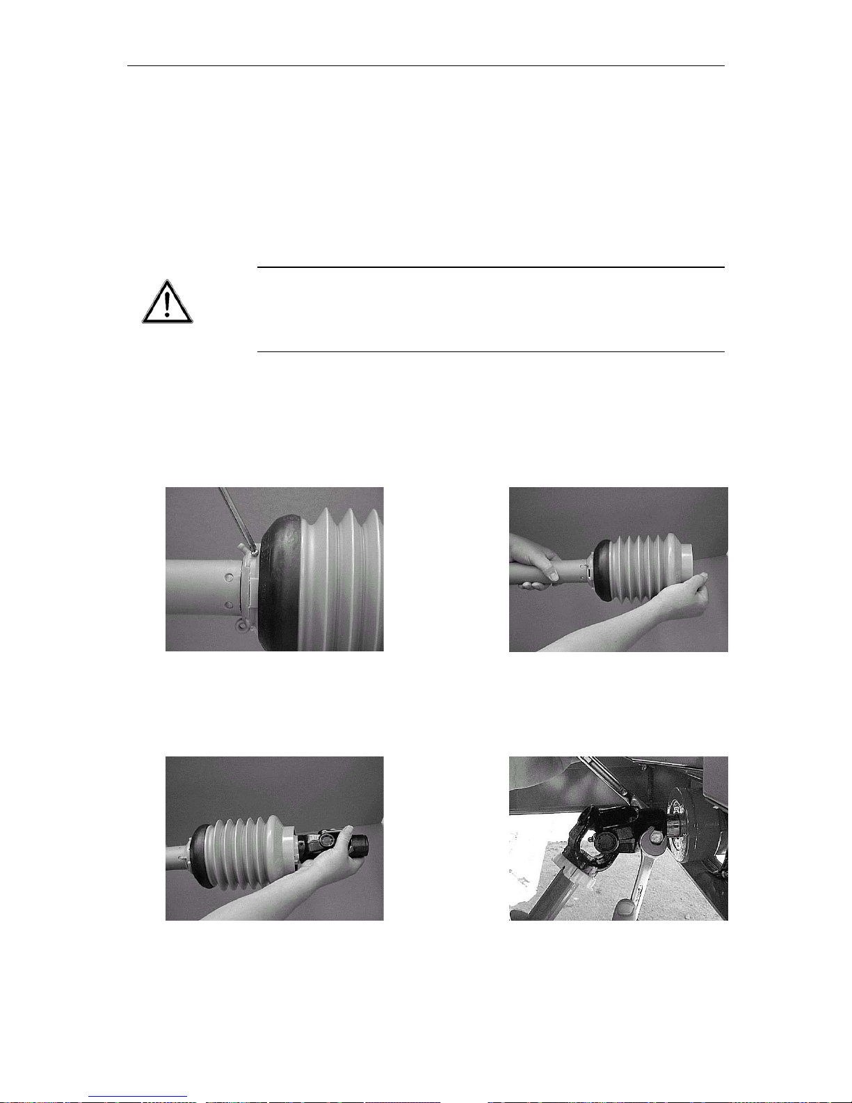
Fitting and removing the pto shaft
Injury or death hazard due to rotating shaft
• Before fitting or removing the pto shaft, make sure that the pto drive is disengaged, the tractor engine switched off and the ignition key removed.
Always fit the shaft the correct way round. The end marked with a tractor symbol must be fitted on the tractor side.
1.
Unscrew the locking screw
2.
Turn the guard muff into its unlocked
position
3.
Pull the shaft out
4.
Remove the guard muff and grease
the pto spline shaft. Place the pto
shaft in position and tighten the bolt
DANGER
Page 25
Erreur ! Style non défini. Erreur ! Style non défini.
23
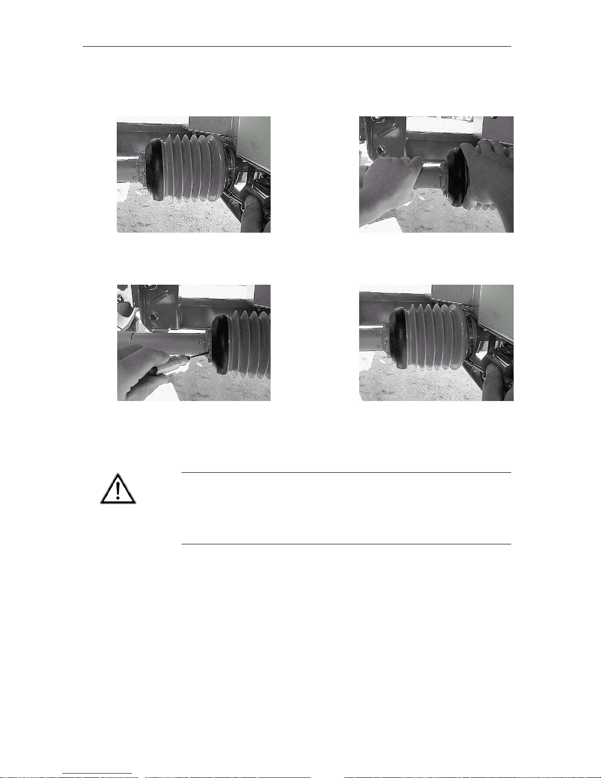
5.
Pull the guard muff over the pto CV
joint onto the housing boss and place the banjo clip into position (do not
tighten).
6.
Turn the guard muff into its locked
position.
7.
Screw in locking screw.
8.
Tighten banjo clip.
• Before engaging the pto drive, make sure that the correct tractor pto speed
is selected to match the recommended speed of the implement. (Respect
all details given in the spreading chart and the max. allowable pto speed.)
Drive shaft damage when engaging the pto drive
The pto drive shaft and the agitator drive can suffer damage if the pto drive is
engaged at high tractor engine speeds.
• Engage the pto drive at lower tractor engine speeds to avoid sudden overload to the drive shaft and agitator drive.
• Make sure that pto shafts, protector tube and end gaiter, as well as extension gaiters on the side
of the fertiliser spreader, are correctly in place and in good condition!
• When detaching the pto shaft, place it in the holder provided on the fertiliser spreader.
• Do not use the safety chain to support the shaft when not in use.
IMPORTANT
Page 26

Erreur ! Style non défini. Erreur ! Style non défini.
24
5.8 Fitting and connecting the hydraulic metering slide
controls
Injury hazard through crushing from remote control elements
The remote control elements (positioning lever, metering slides) can cause
crushing and amputation injuries.
• When activating control levers i.e. metering slides, ensure that no one is in
the vicinity of any moving parts.
Injury hazard due to defective or incorrectly sealed hydraulic hoses
Hydraulic fluid escaping under high pressure can penetrate the skin and cause
serious injuries.
• Regularly check all hoses at least every six months and before each season
commences, for mechanical defects e.g. cuts, abrasions, crushed sections,
kinks, tears, leaks, porosity, etc. Replace any suspect hoses immediately
before operating the machine.
• Even when carefully stored and correctly used, hoses and hose connecti-
ons undergo a natural aging. Therefore, their stocking and operational periods should not be exceeded.
• The useful life of an undamaged hose should be limited to six years, inclu-
ding a possible maximum two-year stocking period.
• The hydraulic hose manufacturing date is indicated on the hose with the
month and year of manufacture (e.g. SLP 8/00).
• Use suitable protection when locating leaks (safety goggles, gloves, etc.) in
order to avoid injury.
• In case of injury, immediately consult a doctor, as there is a risk of serious
infection!
Storing hydraulic hoses when fertiliser spreader is uncoupled from the
tractor
Hydraulic hoses can be laid between the upper link point and the hopper.
5.8.1 Single acting hydraulic metering control for MDS 55 K /
65 K / 85 K / 735 K / 935 K
The MDS 55 K / 65 K / 85 K / 735 K / 935 K metering slides operate with two
hydraulic cylinders fitted complete with exterior mounted return springs.
Oil pressure closes - Spring tension opens
Connecting the hydraulic metering slide control:
The following hydraulic valves are needed on the tractor:
• Two single acting valves, or
• Two double acting valves with free return, or
one single and one double acting valve with free return
WARNING
WARNING
ATTENTION
ATTENTION
Page 27

Erreur ! Style non défini. Erreur ! Style non défini.
25
Prior to long transport journeys or when filling, close both shut-off valves in the
hydraulic circuit to prevent subsequent opening of the metering slides, should
oil inadvertently escape through the control valves.
If the spreader is to be stored for any length of time, it is recommended that the
metering slides are left open so that spring tension is not weakened. Proceed
as follows :
1. Hydraulically close the metering slides
2. Adjust positioning lever stops to their highest scale level.
3. Open metering slides.
5.8.2 Double acting hydraulic metering control for MDS 55 D
/ 65 D / 85 D / 735 D / 935 D
The metering slides operate with two double acting hydraulic cylinders.
Oil pressure closes – Oil pressure opens
Connecting the hydraulic metering slide control:
The following hydraulic valves are needed on the tractor :
Two double acting control valves
5.8.3 Single acting hydraulic metering control with double
acting mechanism for MDS 55 R / 65 R / 85 R / 735 R /
935 R
The MDS 55 R / 65 R / 85 R / 735 R / 935 R metering slides operate with two
single acting hydraulic cylinders complete with externally mounted return
springs.
Oil pressure closes – Spring tension opens
Connecting the hydraulic metering control:
The folowing hydraulic valves are needed on the tractor:
• One single acting or one double acting valve with free return.
Attach the holder brackets for the shut-off valves to a suitable place on the tractor.
Prior to long transport journeys or when filling, close both shut-off valves to the
double acting mechanism to prevent subsequent opening of the metering slides,
should oil inadvertently escape through the control valves.
If the spreader is to be stored for long periods, it is recommended that the metering slides are left open so that spring tension is not weakened. Proceed as follows:
1. Hydraulically close the metering slides.
2. Adjust positioning lever stops to their highest scale level.
3. Open metering slides.
ATTENTION
ATTENTION
Page 28
Erreur ! Style non défini. Erreur ! Style non défini.
26
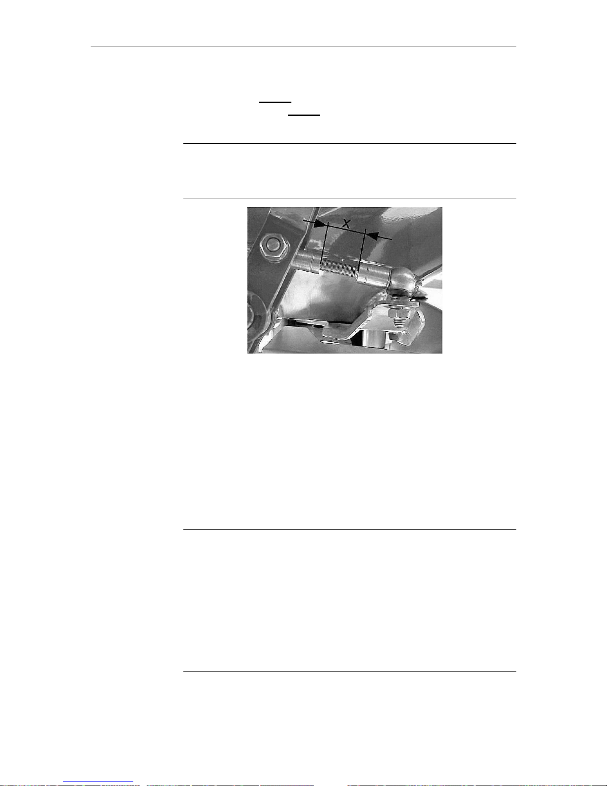
5.8.4 Fitting the single acting hydraulic metering slide
control FHK 4 and the double acting hydraulic metering
slide control FHD 4
Adjusting the knuckle joints
The setting dimension "x" of the knuckle joints (viewed from the left-hand side in
direction of travel) must be reduced by 1 mm (one turn in a clockwise direction)
before fitting the hydraulic cylinder.
5.8.4.1 Fitting the single acting hydraulic metering slide
control FHK 4 (Optional equipment for MDS 55 M / 65
M / 85 M / 735 M / 935 M)
This metering slide control operates with one single acting control valve (trailer
connection).
Oil pressure closes – Spring tension closes
Connecting the hydraulic metering control:
The cylinder for the hydraulic metering slide control FHK4 is fitted to the righthand side of the spreader (viewed in direction of travel).
Before connecting the hydraulic cylinder to the positioning lever, check that its
assembly length is correct when metering slides are closed and the cylinder is
fully extended.
The cylinder length can be adjusted by releasing the locknut and rotating the
piston fork yoke.
Incorrect assembly of the hydraulic cylinder can result in bent positioning levers and pins. (See separate assembly information.)
Prior to long transport journeys or when filling, close the shut-off valve where
the hydraulic circuit is connected, to prevent subsequent opening of the metering slides.
ATTENTION
ATTENTION
Page 29

Erreur ! Style non défini. Erreur ! Style non défini.
27
If the spreader is to be stored for long periods, it is recommended that the metering slides are opened, so that the spring tension is not weakened.
If the positioning lever's hydraulic cylinder fails to completely open, then the
lever's leaf spring, to which the hydraulic cylinder is attached, can be unscre-
wed.
5.8.4.2 Fitting the double acting hydraulic metering slide
control FHD 4 (Optional equipment for MDS 55 / MDS
65 / MDS 85 / 735 M / 935 M)
This hydraulic metering slide control operates with one double acting control
valve.
Oil pressure closes - Oil pressure opens
Connecting the hydraulic metering control:
The cylinder for the hydraulic metering slide control FHD 4 is fitted to the righthand side of the spreader (when viewed in direction of travel).
Before connecting the hydraulic cylinder to the positioning lever, check that its
assembly length is correct when metering slides are closed and the cylinder is
fully extended.
The cylinder length can be adjusted by releasing the locknut and rotating the
piston fork yoke.
Incorrect fitting of the hydraulic cylinder can result in bent positioning levers
and pins. (See separate assembly information.)
If the positioning lever's hydraulic cylinder fails to completely open, the lever's
leaf spring, to which the hydraulic cylinder is attached, can be unscrewed.
ATTENTION
Page 30

Erreur ! Style non défini. Erreur ! Style non défini.
28
5.8.5 Position indicator function: (only for MDS K / R / D)
This indicator allows the position of the shutter slide to be seen from the driver's seat, avoiding unintentional loss of fertiliser.
Shutter slide closed
Shutter slide open
Shutter slide completely open
Page 31

Erreur ! Style non défini. Erreur ! Style non défini.
29
6 Adjusting the fertiliser spreader
6.1 General
Values provided in the spreading charts are derived from practical tests in the
manufacturer's purpose built fertiliser spreader research centre. Settings are
obtained using fertiliser in perfect condition from each respective manufacturer
and spread over the stated spreading width.
We would particularly emphasise that physical characteristics of fertiliser can
vary, even within the same type and brand, due to differences in size of granules, density, surface texture, specific weight and quality of granules, etc.
These variations can influence spreading characteristics quite markedly, which
result in differences in the fertiliser application rates as well as changes in
spread patterns predicted in the spreading charts, therefore making it necessary to recalibrate the fertiliser.
The data provided in the spreading charts can only be used as a guideline. To
ensure greater accuracy the unit should be recalibrated for application rate, and
the spread pattern should be checked over the desired width with the help of
the practical test kit, every time fertiliser is changed, even when using different
bags of the same fertiliser.
We suggest the use of only quality fertiliser from well-known suppliers, preferably those fertilisers listed in the spreading charts. If you need to use fertiliser
not listed, please contact us.
Spreading of Urea
This highly concentrated nitrogen fertiliser has a wide variation of quality and
particle sizes, due to the great number of importers handling this product.
It is therefore essential to recalibrate the unit every time this fertiliser is used.
Also note that Urea is very susceptible to wind variations and moisture absorbtion.
Pay special attention when setting the spreader. Even a very small error in setting can result in a large change in spread pattern.
We must stress that no liability can be accepted for consequential losses
or damages due to spreading errors.
ATTENTION
Page 32
Erreur ! Style non défini. Erreur ! Style non défini.
30
6.2 Attachment height
Attachment height of the fertiliser spreader
Danger of injury from unintentional contact with spreading discs.
• Max. allowable attachment height measured from the ground
to the un-
derside of the frame in normal spreading mode: Dimension A 85 cm and
Dimension B 85 cm.
• Max. allowable attachment height measured from the ground
to the un-
derside of the frame in late top dressing mode: Dimension A 77 cm and
Dimension B 83 cm.
• The dimensions given in the spreading charts are always taken in the field
from the top of the crop to the underside of the frame (Dimension at points
A and B).
• If the max. allowable attachment height from ground level
in normal
spreading mode is exceeded, the unit should be set up using the values
for late top dressing.
6.2.1 Attachment height for normal spreading
Attach the fertiliser spreader to the tractor using the settings given in the spreading chart.
Settings from the spreading chart:
Attachment height above crop level A + B e.g. 50 / 50
The fertiliser spreader attachment height dimension at both points A and B is 50
cm above crop level.
6.2.2 Attachment height for late top dressing
Attach the fertiliser spreader to the tractor using the settings given in the spreading chart.
Settings from the spreading chart:
Attachment height above crop level A + B e.g. 0 / 6
The fertiliser spreader attachment height dimension at point A is 0 cm (i.e. same height as crop level) and the dimension at point B is 6 cm above crop level.
WARNING
Attachment example
Attachment example
B
(85 cm)
A
(85 cm)
B
(83 cm)
A
(
77 cm
)
Ground level-
Ground level
Maximum allowable attachment
height in normal spreading mode
Maximum allowable attachment
height in late top dressisng mode
Page 33

Erreur ! Style non défini. Erreur ! Style non défini.
31
6.3 Hopper capacity / Hopper extension sets
The basic hopper capacity of the fertiliser spreader is between 500 and 900
litres, depending on spreader model. Capacity can be increased by adding one
or more extension sets in various sizes.
When increasing hopper capacity by adding extension sets, take note of the following:
• When filling, the maximum payload must not be exceeded. If the loading
height exceeds 1250 mm a suitable mechanical loading system should be
used e.g. front-end loader.
• When fitting the extension sets, only use the self-locking nuts provided.
Checking the hopper contents
• An inspection window is provided on all MDS fertiliser spreaders (except
MDS 55 / 65 / 85). The M653 and M863 extension sets are also equipped
with inspection windows. These inspection windows facilitate the control of
the hopper contents e.g. when checking what is left in the hopper.
6.3.1 Calculation of maximum loading
The specific weight of Thomas potash = 1.36 kg/l. As the maximum payload of
the MDS 935 fertiliser spreader is 1800 kg, the spreader should not be loaded
with more than a maximum of 1323 litres of Thomas potash.
litres
lkg
kg
ge
fertiliserofweightspec
payload
capacityMax 1323
./36.1
1800
:..
.
.max
. ==
6.3.2 Hopper level scale
For control of the hopper level i.e. amount of product left to be spread in litres.
(Accuracy of each mark max. +/- 10 %.)
The scale allows the operator to calculate how long
spreading can continue before refilling is necessary.
This avoids unnecessary refilling, leading to a reduction in the amount of product remaining after
field operations are completed.
IMPORTANT
Page 34

Erreur ! Style non défini. Erreur ! Style non défini.
32
6.4 Setting application rates on the
MDS 55 M / MDS 65 M / MDS 85 M / 735 M / MDS 935 M
A potential crushing and amputation hazard exists when carrying out
adjustments or other work on the fertiliser spreader.
Rotating parts (e.g. spreading discs, pto shaft) and remote controlled machine
elements (e.g. adjusting lever, metering slides) can cause serious injuries.
• Before carrying out adjustments or other general work such as maintenance
or cleaning, disengage the pto drive, stop engine and remove the ignition
key.
• Wait until the rotating parts have come to a standstill before approaching
the machine.
Application rates are adjusted by means of an adjusting lever stop (1) on a large
scale segment, which is extremely easy and positive to use.
An application rate with its corresponding position on the scale segment is selected from the calibration charts, according to the desired forward speed. The
stop on the segment is positioned so that its edge is aligned to the position selected. (Marked edge (2) aligned to the selected position.)
The stop adjustment of one hole position corresponds to two scale segment positions. If only a single segment position adjustment is needed, this can be achieved by turning the handle (3) over the stop and slotting it into the offset holes (see photos 1 and 2).
Due to the proportional scale segmentation, not every value can be selected.
Select the nearest higher or lower selectable position. As the scale segmentations are so small, application rate variations will be minimal.
Photo 1 Metering slide position 350 Photo 2 Metering slide position 130
Closing the shut-off valves (only valid for single acting metering slide
control)
Close the shut-off valves before all transport journeys and before parking or
disconnecting the unit, as most valves are not entirely oil tight, thus allowing the
spring tension of the hydraulic metering control to overcome oil pressure, resulting in the metering slides opening and fertiliser escaping from the hopper.
WARNING
ATTENTION
Page 35

Erreur ! Style non défini. Erreur ! Style non défini.
33
6.5 Setting application rates on the
MDS 55 K / R / D MDS 65 K / R / D MDS 85 K / R / D
MDS 735 K / R / D and MDS 935 K / R / D
A potential crushing and amputation hazard exists when carrying out
adjustments or other work on the fertiliser spreader.
Rotating parts (e.g. spreading discs, pto shaft) and remote controlled machine
elements (e.g. adjusting lever, metering slides) can cause serious injuries.
• Before carrying out adjustments or other general work such as maintenance
or cleaning, disengage the pto drive, stop engine and remove the ignition
key.
• Wait until all rotating parts have come to a standstill before approaching the
machine.
An application rate with its corresponding position on the scale segment is selected from the calibration charts, according to the desired forward speed. The
stop on the segment is positioned so that its edge is aligned to the position selected. (Marked edge (2) aligned to the selected position.)
Both left- and right-hand side stops must be equally adjusted to the same scale
position and securely locked in place.
Closing the cut-off valves (only valid for single acting metering slide
control)
Close the shut-off valves before all transport journeys and before parking or
disconnecting the unit, as most valves are not entirely oil tight, thus allowing the
spring tension of the hydraulic metering control to overcome oil pressure, resulting in the metering slides opening and fertiliser escaping from the hopper.
WARNING
ATTENTION
Page 36

Erreur ! Style non défini. Erreur ! Style non défini.
34
6.6 Adjustment of the multi-disc spreading discs
6.6.1 Principle of operation
The disc vanes on the spreading discs can be adjusted to accept various types
of fertiliser, different fertiliser operations, as well as different working widths.
Different spreading operation mode possibilities are :
1. Normal spreading.
2. Border spreading either to the left- or right-hand side when in the normal
spreading mode.
3. Late season top dressing.
4. Border spreading either to the left- or right-hand side when in the late sea-
son top dressing mode.
• Each disc is equipped with two identical disc vanes.
• Each vane consists of a main vane with an extension vane.
• The main vane of the right-hand spreading disc is identified with the letters
BR and its corresponding extension vane with the letters AR.
• The main vane of the left-hand spreading disc is identified with the letters
BL and its corresponding extension vane with the letters AL.
• Each vane angle can be increased or decreased. Also, the vane's effective
length can be shortened or increased.
Decreasing the vane angle means that the vane is moved from higher to lower
numbers. The numbers are stamped into the discs.
Increasing the vane angle means that the vane is moved from lower to higher
numbers. The numbers are stamped into the discs.
Shortening the vane length means that the slidable vane extension is moved
towards the disc centre and locked in place.
Increasing the vane length means that the slidable vane extension is moved
away from the disc centre and locked in place.
Decreasing the vane
angle
Increasing the vane
angle
Shortening the vane
length
Increasing the vane
length
Page 37
Erreur ! Style non défini. Erreur ! Style non défini.
35
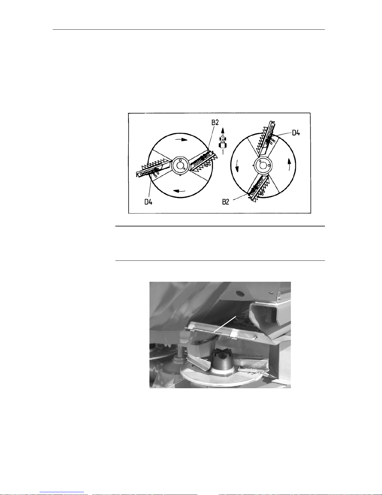
6.6.2 Adjusting the disc vanes
Obtain recommended setting positions of the disc vanes from the calibration
charts in accordance with the fertiliser to be used, the type of fertiliser operation
mode to be undertaken, as well as the desired working width.
Disc vanes on both discs must be positioned so that one vane is at the D4 position with the other set at the B2 position (see diagram).
Positioning the vanes
Positioning of the vanes on the right-hand disc must correspond exactly to the
same positions of the vanes on the left-hand disc (border spreading is the exception to this rule).
An adjusting lever will be found on the right-hand frame side (1).
This adjusting lever is used to adjust the vane positions as well as for changing
the discs.
When changing or checking that the discs are securely fitted, protective gloves
should be used as there is a danger of injury due to hands coming into contact
with sharp edges.
Example: D4-B2
ATTENTION
1
Page 38
Erreur ! Style non défini. Erreur ! Style non défini.
36
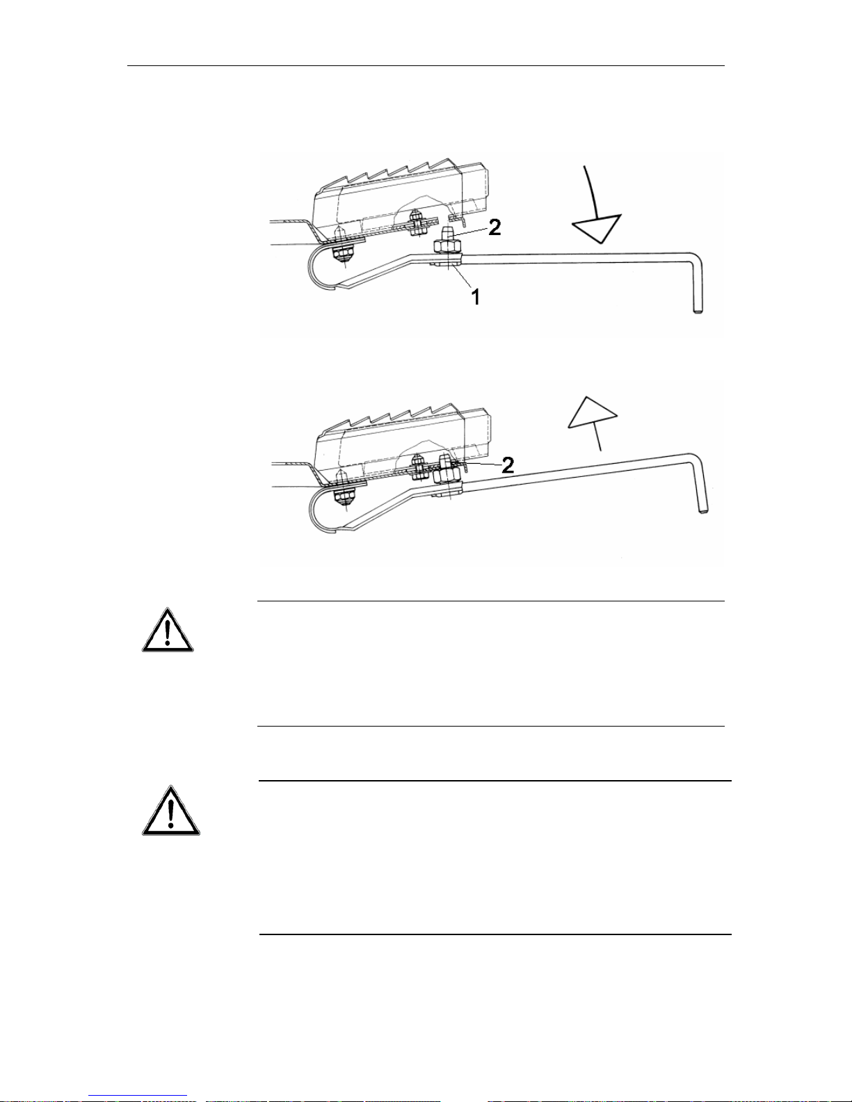
Slot the adjusting lever into the leaf spring under the disc and press downwards
to disengage the notch pin (2).
Adjust vane angle and length and re-engage the notch pin.
Engaging the disc vanes and replacing the adjusting lever
Serious injury hazard from incorrectly attached components.
• After adjusting the vanes, the notch pin must be completely returned into its
locked position.
• The adjusting lever must be securely reclipped into place on the frame befo-
re the pto drive is engaged.
WARNING
The left spring should only be pressed down just enough to disengage the
notch stop.
Over tensioning of the leaf spring will result in loss of necessary tension to safely secure the disc vane.
Check leaf spring tension regularly!! If tension is too weak it means the
notch stop is not fully engaged and the leaf spring should be immediately replaced for security reasons.
WARNING
Page 39

Erreur ! Style non défini. Erreur ! Style non défini.
37
6.6.3 Adjustment according to the spreading charts
Depending on :
• Type of fertiliser,
• Working width and the
• Mode of operation.
The
• Spreading disc type,
• Vane setting,
• Spreader attachment height and the
• Pto speed
must be set according to the spreading chart. Spreader attachment height is
always measured from the top of the crop.
Normal spreading mode:
Example: C3-B2
Both discs have one vane mounted in the C3 position and the other in the B2
position.
Example: A2-A2
Both vanes on the disc nearest the border are placed in the A2 position. The
vanes on the other disc remain in their normal spreading mode.
Late top dressing mode
Example: C3-C2
Mounting height is measured from the top of the crop e.g. when 0/6 is indicated:
Dimension A = distance from the top of the crop is 0 cm. Dimension B = distance from the top of the crop is 6 cm. Both discs have one vane mounted in
the C3 position and the other mounted in the C2 position.
Example: A3-A3
Both vanes on the disc nearest the border are placed in the A3 position. The
vanes on the other disc remain in their late top dressing mode.
Normal spreading
Border spreading du-
ring normal sprea-
ding
Late top dressing
Boundary spreading
during late top dres-
sing
Page 40

Erreur ! Style non défini. Erreur ! Style non défini.
38
Page 41

Erreur ! Style non défini. Erreur ! Style non défini.
39
6.6.4 Setting disc vanes for fertilisers not listed in the sprea-
ding charts
6.6.5 DiS
The KUHN fertiliser identification kit DiS (optional equipment) gives quick and
easy help in determining the correct spreader settings for numerous unknown
fertiliser products.
Designed to fit in normal size pockets the kit can also be used in the field.
The fertiliser to be identified is first grouped according to its chemical makeup. Then, using "mug shot" reference photos, the actual granules are identified and the fertiliser characteristics can be determined. After identification
the fertiliser spreader setting can be determined from the accompanying
table.
6.6.6 PtK
A practical test kit, supplied as optional equipment, offers a simple and quick
method for checking the spread pattern. By using this kit it is possible to obtain settings for fertilisers not listed in the spreading charts.
For a quick check of the spreader settings a one-pass method is recommended.
To obtain more accurate results and reduction of negative calibration error influences, such as side wind, a three-pass method is recommended.
6.6.6.1 Three-pass method (PtK):
• Choose a fertiliser from the spreading charts that has the nearest characte-
ristics to the one that needs to be used and adjust the fertiliser spreader to
these settings.
• Test on a dry calm day so that weather conditions do not influence the re-
sults.
• A test area should be chosen which is horizontal in both directions and is
large enough to achieve 3 tramlines over a length of approx. 60 - 70 m.
• Carry out the test, either on freshly mown grass or in a field with low vegeta-
tion (max. 10cm), and make sure that the 3 tramlines run parallel to each
other. When carrying out a test without pre-set tramlines the tracks must be
measured using a tape measure and marked with suitable post markers.
• The three tracks must not contain any notable bumps or hollows as these
could cause a shift in spread pattern.
• Place two collecting containers one behind the other (1m apart) as per the
following sketch. One pair in each overlap zone and one pair in the centre
of the middle tramline.
Page 42

Erreur ! Style non défini. Erreur ! Style non défini.
40
1/2
Working width
1/2
123
• Make sure individual containers are level. Containers set at an angle can
lead to measuring errors.
• Set the fertiliser spreader at the same height on the left- and right-hand si-
des in accordance with the information in the spreading charts, paying attention that the mounting height is taken from the top edge of the collecting
trays.
• Before testing, check the functioning and condition of the spreading ele-
ments (discs, vanes, metering slides).
• Carry out a calibration check. Adjust the left- and right-hand metering slides
according to results obtained, and lock in place. Undertake the spread pattern test using this aperture setting. If it is felt that the fertiliser collected in
the trays is not enough for a clear analysis, merely travel over the trays twice. Do not change the metering slide aperture.
• Select only a tractor speed of between 3 and 4 km/h so as to keep tractor
and spreader as steady as possible. Keep the metering slides to the same
setting. It is irrelevant to the test that the actual application rate is higher,
as this is only a result of the slower tractor speed for test purposes. Keep
the speed of the tractor constant throughout the test.
• Spread along the tramlines 1 - 3, one after the other. Open the open/close
shutter slides approx. 10 m before reaching the collecting trays and close
approx. 30 m after passing them. If the collected volume is insufficient, repeat all 3 passes.
• Pool the contents of each pair of containers and pour into the respective
measuring tubes i.e. left-hand pair in left-hand tube, middle pair in middle
tube, right-hand pair in right-hand tube. The evenness of the spread pattern
can now be judged from the level in each tube.
Page 43

Erreur ! Style non défini. Erreur ! Style non défini.
41
Following results are possible:
Same quantity in all three tubes
(allowed tolerance ± one mark).
The spread pattern is acceptable.
Lop-sided spread pattern.
Unacceptable.
Too much fertiliser in the overlap zone.
Unacceptable.
To little fertiliser in the overlap zone.
Unacceptable.
6.6.6.2 One-pass method (PtK):
• Choose a fertiliser from the spreading charts that has the nearest characte-
ristics to the one that needs to be used and adjust the spreader to these
settings.
• Test on a dry calm day so that the weather conditions do not influence the
result.
• A test area should be chosen which is large enough to achieve a tramline
length of 60 to 70m.
• Carry out the test, either on freshly mown grass or in a field with low vegeta-
tion (max. 10cm).
• The tramline must not contain any notable bumps or hollows as these could
cause a shift in the spread pattern.
• Place two collecting containers, one behind the other (1m apart), in the overlap zone (between tramlines) and one container in the centre of the
middle tramline (as per following sketch).
A
B
C
D
working width (AB)
Page 44
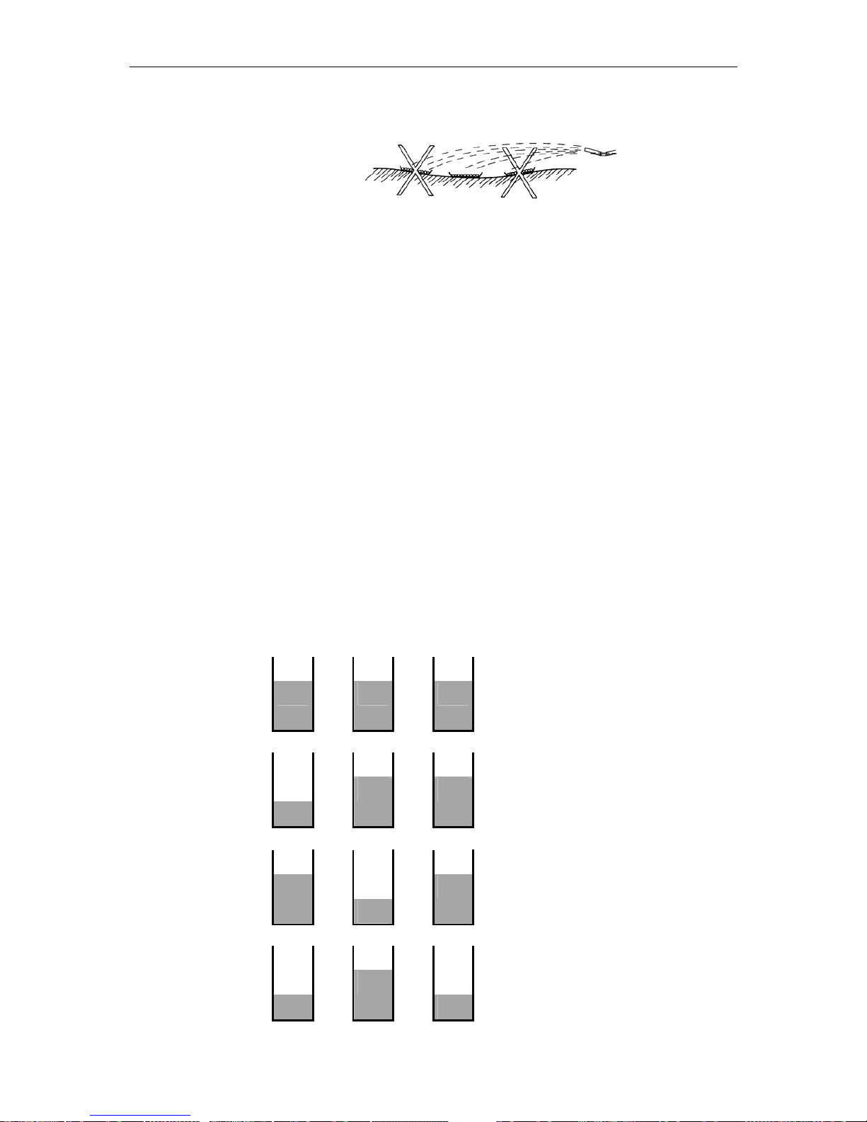
Erreur ! Style non défini. Erreur ! Style non défini.
42
• Make sure individual containers are level. Containers set at an angle can
lead to measuring errors.
• Set the fertiliser spreader at the same height on the left- and right-hand sides, in accordance with the information in the spreading charts, paying attention that the mounting height is taken from the top edge of the collecting
trays.
• Before testing, check the functioning and condition of the spreading ele-
ments (discs, vanes, metering slides).
• Carry out a calibration check. Adjust the left- and right-hand metering slides
according to results obtained, and lock in place. Undertake the spread pattern test using this aperture setting. If it is felt that the fertiliser collected in
the trays is not enough for a clear analysis, merely travel over the trays twice. Do not change the metering slide aperture.
• Select only a tractor speed of between 3 and 4 km/h so as to keep tractor
and spreader as steady as possible. Keep the metering slides to the same
setting. It is irrelevant to the test that the actual application rate is higher,
as this is only a result of the slower tractor speed for test purposes. Keep
the speed of the tractor constant throughout the test.
• When spreading along the tramline, open the open/close shutter slides ap-
prox. 10 m before reaching the collecting trays and close approx. 30 m after
passing them. If the collected volume is insufficient, make another pass.
• Pool the contents of each exterior pair of containers and pour all three a-
mounts into the respective measuring tubes i.e. left-hand pair in left-hand
tube, middle single container in middle tube, right-hand pair in right-hand
tube. The evenness of the spread pattern can now be judged from the level
in each tube
Following results are possible:
A
Same quantity in all three tubes (allowed
tolerance ± one mark). The spread pattern is acceptable.
B
Lop-sided spread pattern. Unacceptable.
C
Too much fertiliser in the overlap zone.
Unacceptable.
D
Too little fertiliser in the overlap zone. U-
nacceptable.
Page 45

Erreur ! Style non défini. Erreur ! Style non défini.
43
Following hints for correcting the spread pattern are applicable for
both one- and three-pass methods
If the results obtained are as shown in Example B check that both right- and
left-hand meterig slides open exactly equally.
Check that tramline widths are equally spaced and parallel and that there
has been no cross-wind during the test run.
If results obtained are as shown in Example C the setting given for the second
disc vane position in the spreading charts should be decreased (smaller figure
selected) so that the fertiliser in the overlap zone is reduced.
Example:
Given settings : C3 - B2
New setting : C3 - B1
If results obtained are as shown in Example D the setting given for the second
disc vane position in the spreading charts should be increased (higher figure selected) so that fertiliser in the overlap zone is increased.
Example:
Given settings: C3 - B2
New setting : C3 - B3
If the angle correction for the second disc vane is not sufficient, additional correction can be obtained by increasing the vane length.
Example: B3 C3
Lengthening this vane will result in more fertiliser being taken from the middle
and thrown into the overlap zone area.
If the overall spreading width is too wide or too narrow, the setting given for
the first disc vane position should be decreased or increased to the next given
working width setting given in the spreading chart.
Example: Spreading width too wide
Example:
E5 - C2 (24 m)
E4 - C2 (21 m)
Page 46

Erreur ! Style non défini. Erreur ! Style non défini.
44
6.7 One-sided spreading
6.7.1 One-sided spreading MDS 55 M / MDS 65 M / MDS 85 M
/ MDS 735 M / MDS 935 M
For left- or right-hand spreading, uncouple the round handled application control
lever from the flat handled one and, depending on the desired spreading side,
bring the corresponding application control lever to the stop point.
• Operate the round handled application lever: right-hand side spreading
• Operate the flat handled application lever: left-hand side spreading
6.7.2 One-sided spreading MDS 55 K / MDS 65 K / MDS 85 K /
MDS 735 K / MDS 935 K
To spread to the left or right, the control valve is depressurised on either the
left- or right-hand side allowing spring tension to pull the corresponding metering slide to its stop.
6.7.3 One-sided spreading MDS 55 D / MDS 65 D / MDS 85 D /
MDS 735 D / MDS 935 D
To spread to the left or right, operate the corresponding control valve, allowing
the hydraulic cylinder to move the corresponding metering slide to its stop.
6.7.4 One-sided spreading MDS 55 R / MDS 65 R / MDS 85 R /
MDS 735 R / MDS 935 R
To spread to the left or right, close or open the corresponding shut-off valve to
the double acting mechanism to depressurise the control valve, allowing spring
tension to pull the corresponding metering slide to its stop.
6.8 Yield and environmental optimised border spreading
With yield optimised border spreading a fertiliser distribution pattern is produced
so that only a minimum amount of fertiliser is thrown over the field edge while,
at the same time, the desired application rate up to the edge of the field is only
slightly reduced.
With environmental optimised boundary spreading, no fertiliser is thrown over
the field edge but a reduction in application rate up to the edge of the field must
be accepted.
6.8.1 Yield optimised border spreading in the first tramline
Adjust the vanes on the spreading disc nearest the field edge in accordance
with the information from the spreading chart. The metering slide is set to the
same position as the metering slide on the field side.
Page 47

Erreur ! Style non défini. Erreur ! Style non défini.
45
6.8.2 Environmental and yield border spreading using the
border spreading limiter GSE 7 (optional equipment).
Only one metering slide is opened
With the border spreading limiter GSE 7, it is possible to adjust the spreading
width between 0.75cm and 2m from the tractor centre up to the edge of the field
(on either left- or right-hand side). The metering slide facing the field edge is
closed. When border spreading, the border spreading mechanism must be lowered. To return to normal full width spreading, the border spreading mechanism must be folded up.
6.8.3 Environmental and yield border spreading using the
border spreading limiter TELIMAT T1 (optional equipment)
The Tellimat T1 is deployed from the first tramline (1/2 working width from the
field edge).
6.9 Spreading on small field strips
Adjust the vanes on both spreading discs according to the settings given for
border spreading in the spreading charts.
7 Calibration check / Purging unused fertiliser
7.1 Calculating the mean application rate
To ensure accurate application rates, we recommend that a new calibration
check is carried out each time a new type or a different batch of fertiliser is used. Calibration must be done when the machine is stationary with the pto revolving at 540 rpm, or at the recommended speed given in the spreading charts
for individual fertilisers, or when driving over a test length.
Calculation of precise tractor foward speed:
For more precise measurement of tractor forward speed to that given by the
tractor tachometer, drive a measured 100m on a field with the hopper half full
and measure the time taken.
Tractor speeds outside the above scale can be calculated using the following
formular :
hkmge
mfortimemeasured
speedTractor /10
.sec36
360
:..
100
360
==
Page 48

Erreur ! Style non défini. Erreur ! Style non défini.
46
Determination of the required mean fertiliser output per minute:
The calibration check is usually only carried out using one hopper outlet. However, the fertiiser quantity required is calculated for both hopper outlets i.e. total working width, therefore the calculated quantity should be halved for calibration purposes.
min/
600
)/()()/(
kg
hakgratenApplicatiomwidthWorkinghkmspeedTractor
=
×
×
min/72
600
/30018/8
: kg
hakgmhkm
Example =
×
×
Therefore 36 Kg/min must flow through one hopper outlet in 60 seconds. In order to determine the correct metering slide setting, several attempts may be required. (Use values provided in the spreading charts as a guideline.)
Output figures for a selection of application rates and tractor speeds are already
provided in the spreading charts.
This calibration can also be carried out using a calibration slide rule (see below).
For example: Position the 300 kg/ha figure below the 18m figure on the working width scale and then read off the value for kg/min above 8 km/h on the
speed scale. The result shows that 72 kg/min will be the required mean fertiliser output from both shutter outlets combined.
Only by driving at the given speed consistently can the desired application rate be achieved!
ATTENTION
e.g. 10% higher forward speed
10 % less application rate
Page 49

Erreur ! Style non défini. Erreur ! Style non défini.
47
7.2 The calibration check process
Calibration check nozzle holder
This holder allows the calibration check nozzle (1)
to be onhand at all times
• Close the metering slide by hand or with the
hydraulic control.
• Disengage the tractor pto drive. Stop the en-
gine and remove the ignition key.
• Fill with fertiliser. The calibration check
should only be undertaken on the left-hand side of the spreader (viewed in direction of travel).
• Remove the adjustment lever located in its
holder on the spreading disc shroud and release the synthetic castellated disc hub nuts.
• Remove both spreading discs from their hubs
and locate the calibration check nozzle (1)
under the left-hand outlet (viewed in direction
of travel).
• Position the metering slide stop to give the
desired application rate according to information given in the spreading charts. Engage
the pto drive at the required rpm speed, as given in the spreading charts.
•
Process as much fertiliser as possible.
The greater the volume processed the more
precise the calibration check.
Injury hazard from rotating parts
Rotating hubs can cause bruising, cutting and crushing injuries.
• Stand well away from the rotating hubs during the calibration check.
WARNING
1
1
Page 50

Erreur ! Style non défini. Erreur ! Style non défini.
48
Injury hazard from rotating pto shaft
Rotating pto shafts can lead to cutting, bruising and crushing injuries or death.
• When the pto shaft is turning, the metering slides must always be activated
from the tractor seat.
Open the left-hand metering slide (from tractor seat) for the chosen length of
time. An output of Kg/min must be ascertained. It is preferable to allow a full 60
seconds, but as this may involve a greater capacity than the bucket will hold, a
time of 20 to 30 seconds can be used, but remember to multiply the results accordingly, to obtain a theoretical minute.
Weigh the amount collected, remembering to subtract the weight of the bucket.
If actual weight differs from the guideline figure given in the spreading chart, alter the position of the metering slide stop and repeat the calibration check. E.g.
If 10% too little fertiliser is collected when the metering stop is at 150, as the
scale is proportionally laid out, select a new position of 150 + 10% = 165.
You may need to repeat the process several times before the correct application rate is achieved. Remember, the actual weight measured must be half of
the application rate required, as only one half of the total width is used in the calibration check. Once correct application rate is achieved, disengage pto drive,
switch off engine and remove the ignition key.
Refit the discs, making sure that right- and left-hand discs are correctly positioned on their respective sides. Each disc is indicated with either L (for left-hand
side) or R (for right-hand side).
Refit the synthetic castellated disc hub nuts, making sure they are not crossthreaded, and tighten by hand. Turn the spreading discs carefully by hand to
make sure they do not foul and, using the adjusting lever, securely but lightly
tighten, taking care not to overtighten.
Defective synthetic castellated disc hub nuts
Spreading discs are fast rotating parts and could flutter if the synthetic castellated disc hub nuts are faulty or not securely fastened.
• Regularly check castellated nuts (threads and cracks etc.).
• Replace defective castellated nuts immediately.
7.3 Purging unused fertiliser
To keep the spreader in good condition it is recommended that all unused fertiliser is removed immediately after field operations are completed. To purge the
hopper, follow instructions as per the calibration check in section 7.2. It is recommended that the metering slides are set to their max. opening position.
Injury hazard from rotating parts
Rotating hubs can lead to cutting, bruising and crushing injuries.
• Do not stand in the vicinity of rotating hubs when removing unused fertiliser.
Any left-overs can be removed from inside the hopper with a bush and pan.
Make sure the pto drive is disengaged, tractor engine is switched off and the
ignition key is removed.
DANGER
IMPORTANT
WARNING
Page 51

Erreur ! Style non défini. Erreur ! Style non défini.
49
Page 52

Erreur ! Style non défini. Erreur ! Style non défini.
50
8 Service and maintenance
Jack-knife danger
Non-observance of the safety rules can lead to serious injury or death.
• Do not stand close to the fertiliser spreader when it is in a raised position.
• When servicing or maintaining the fertiliser spreader in its raised position,
make sure it is supported by suitable support blocks.
Injury hazard in crushing and cutting areas
Remote controlled elements (control lever, metering slides) can lead to crushing
and amputation injuries.
• Make sure during service and maintenance that no one is in the vicinity of
remote controlled elements (control levers, metering slides).
8.1 Cleaning
To keep the spreader in good condition, we recommend that the unit be thoroughy cleaned with a low pressure water jet immediately after field operations
are completed.
When cleaning, make sure that the metering control mechanism and metering
flow tracts are cleaned from underneath.
Only wash in suitably designated areas that have been specifically designed to
collect and remove environmentally damaging elements, such as oil and fertiliser, without endangering the surrounding environment.
When washing with pressure washers, never direct the jet directly into any electrical elements, exposed hydraulic machine parts, exposed bearings or decals.
After drying off the spreader, we recommend that it is treated with environmentally acceptable biodegradable anti-corrosion liquid or spray such as
KAMSTAR 400 BIO.
Treating stainless steel components
Due to production processes, many fertiliser products contain Fe (iron), for example, Thomas potash. These fertilisers can damage the oxidation layer on
stainless steel components. It is recommended that stainless steel components
are treated with etching paste such as POLINOX-P. Take note of the manufacturers instructions before using.
8.2 Lubrication
8.2.1 Pto shaft
Slide the pto guard towards the rear to expose the grease nipple. Take note of
all safety and assembly instructions in section 5.7 "Fitting the pto shaft". Finally,
grease the shaft in accordance with the instructions supplied by Walterscheid.
DANGER
WARNING
Page 53

Erreur ! Style non défini. Erreur ! Style non défini.
51
8.2.2 Agitator shaft and agitator
Lubricate the agitator shaft and agitator before and after each season with graphite grease, as per section 5.5, photos 3 and 4.
8.2.3 Metering slides, positioning levers, links and ad-
justment scale segment
For trouble-free operation of the hydraulic metering control, it is recommended
that the metering slides, positioning levers and control links are adequately
greased to ensure free movement.
8.2.4 Disc hubs
The disc hub should be lubricated regularly with graphite grease to ensure trouble-free movement of the synthetic castellated disc hub nuts.
Check the synthetic castellated disc hub nuts for cracks and damage and renew
immediately if defective.
8.3 Gearbox oil level
The gearbox has a constant lubrication system and is maintenance-free in normal operating conditions.
The oil level is correct when oil reaches the lower edge of the opened filling/control plug when the fertiliser unit is absolutely level.
An oil change is recommended every 10 years, or at shorter intervals if high
pressure washers have been frequently used, as well as when fertilisers with
high dust content have been employed.
The control plug also serves as the filler and drain plug.
Correct oil capacity is 2.2 litres of SAE 90 API-GL-4 gear oil.
Disposal of old oil
Only dispose of old oil in an environmentally correct way.
ATTENTION
Page 54

Erreur ! Style non défini. Erreur ! Style non défini.
52
8.4 Wearing parts
Vanes, agitator, metering outlets
If these parts show signs of wearing, deformation, holes or fissures, they must
be replaced to avoid spreading accuracy deterioration. The life of these components is dependent, amongst other things, on the type of fertiliser products
used.
If the distance between the agitator finger and hopper floor is greater than 20 mm, the
agitator must be replaced.
Only by respecting this dimension will it be possible to achieve an even fertiliser output
(constant application rate).
8.5 Checking and setting the metering slide balance and
specially checking the metering slides for seed and slug
pellet spreading
Injury hazard from shearing and crushing elements.
Serious hand injuries can occur during adjustment operations.
• Never operate the metering slide controls, especially hydraulic metering
controls, when a lower link pin or other adjustment gauge is inserted into
the metering slide opening.
• When making adjustments, take especial care around the metering slide
area, which can shear or crush.
8.5.1 Checking the metering slide
Before each season and regularly during the season, the metering slides should
be checked to ensure that they open simultaneously and evenly.
When spreading seed or slug pellets, it should be checked even more particularly that the metering slides open evenly and simultaneously.
• Set the stop and stop lever to position 130 on the application rate proportio-
nal scale (for seed or slug pellets select position 9).
• Open the metering slides up to these previously mentioned stop positions.
WARNING
Max. 20 mm
Page 55
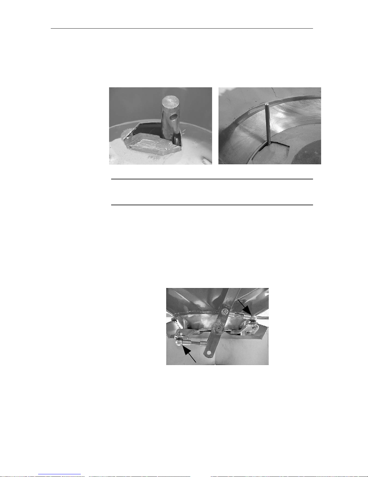
Erreur ! Style non défini. Erreur ! Style non défini.
53
• Place a Ø 28 mm lower link pin in both slide apertures (for seed or slug
pellets Ø 8 mm pins).
• If it is not possible to insert the pins, or the pins have more than 1.5 mm
play (for seed or slug pellets more than 1 mm), the metering slides must
be adjusted.
Equal and simultaneous opening of the metering slides.
Both metering slides must open equally and simultaneously. If this is not the
case they must be adjusted.
8.5.2 Rebalancing the metering slides MDS 55 M / MDS 65 M
/ MDS 85 M / 735 M / 935 M
To adjust the opening of the metering slide, the knuckle joint on one side is detached and turned through one revolution to increase or decrease the metering
slide opening.
Fundamentally, it is important that the metering slides open simultaneously
and equally.
ATTENTION
How to do it!
Page 56

Erreur ! Style non défini. Erreur ! Style non défini.
54
8.5.3 Rebalancing the metering slides MDS 55 K / R / D MDS
65 K / R / D MDS 85 K / R / D MDS 735 K / R / D and
MDS 935 K / R / D
Position the application rate stop in such a way that, when the Ø 28 mm lower
link pins or Ø 8 mm pins for seed and slug pellets, are inserted into the open
left- and right-hand metering slide apertures, there is only a small amount of
play.
By releasing the bolts (1) the application rate quadrant scales (2) can be positioned so that they both read exactly 130 at the application stop point (position 9
for seed and slug pellets).
Fundamentally, it is important that the metering slides open simultaneously
and equally.
Page 57

Erreur ! Style non défini. Erreur ! Style non défini.
55
9 Changing the spreading discs
Essential safety and accident prevention instructions
Before undertaking any adjustments or other work such as cleaning, maintenance, alterations, repairs
or clearing blockages, disengage the pto drive, switch off the tractor engine and remove the
ignition key. Allow all revolving parts to come to a complete standstill. Make sure that no-one can
inadvertently start up the fertiliser spreader while the operator is checking or repairing the unit.
DANGER
Injury hazard from rotating machine elements!
Rotating machine elements (discs, agitator, pto shaft) can cause serious injury or
death.
• Always avoid wearing loose clothing, or clothing with loose parts that are liable
to come into contact with moving parts!
• Avoid wearing clothing with belts, fringes or other items that could get caught
up in moving parts.
• Never get close to moving parts. Keep hands, feet and clothing well away.
• Never reach into the hopper or touch the rotating discs.
• Never climb onto the spreader when it is operating.
• Keep the hopper free of any foreign objects. (Danger from ejected projectiles.)
• Before starting the spreader, make sure there is no-one within the danger area
around the machine. Make sure you have a good all round vision and keep a
special watch out for children!
• Only start up the spreader when all safety devices and guards have been properly fitted and placed in their working positions (e.g. pto shaft guards, disc
shrouds).
IMPORTANT
All bolts (M8 and larger) should be coated with the anti-seizure past provided!
If the anti-seizure paste is not used
• bolts can corrode and seize in place.
• correct removing and refitting of the bolts are not possible.
• the correct locking of the bolted elements is not assured.
9.1 Spreading disc removal
1. Release both synthetic castellated disc hub nuts using the assembly lever located on the fertiliser
spreader.
2. Completely unscrew the synthetic castellated disc hub nuts and remove the spreading discs.
Page 58

Erreur ! Style non défini. Erreur ! Style non défini.
56
9.2 Replacing the extension vanes
1. Unscrew the bolt (5) and remove together with its nut and washer. Disengage the leaf spring (4)
with the help of the assembly lever and slide the old extension vane (7) out of the main vane (6).
Vane pairing:
IMPORTANT
• To avoid spreading errors, when assembling make sure the main and extension
vane combination is correct.
Vane combinations
Spreading disc type M0, M1
Spreading disc example RIGHT
Main vane + Ext. vane Main vane + Ext. vane
Left
BL + AL
Spreading disc
Right
BR + AR
+
5
6
7
4
Page 59

Erreur ! Style non défini. Erreur ! Style non défini.
57
DANGER
Injury hazard from rotating machine elements!
If the extension vanes are assembled using the previously used bolts, the extension
vane could detach itself, causing injury or death.
• With every re-assembly only use new bolts, nuts and washers delivered together
with the vane. Discard the old bolts, nuts and washers.
2. Bolt the new extension vane (7) with the main vane (6) onto the spreading disc using new bolt (5)
new self-locking nut (8) and new washer (12). (Before assembly, smear all bolt threads (M8 and
greater) with anti-seizure paste!)
3. Tighten the bolt so that it lies flat and secure with the spreading disc.
4. To allow the extension vane to be easily adjusted, release the bolt by approx. half a turn.
The bolt must only be released enough to allow extension vane adjustment, but ensuring at the
same time that it lies securely on the main vane. Retighten after adjustment is completed.
5. Repeat the above procedure for all other extension vanes that are to be replaced.
6. Re-assemble both spreading discs. See section 9.5 "Refitting the spreading discs".
5
12
5
6
7
12
8
Page 60

Erreur ! Style non défini. Erreur ! Style non défini.
58
9.3 Replacing the main vane or the complete vane assembly
1. Unscrew the self-locking disc vane leaf spring retaining nut (3) using a 13 mm open ended spanner.
WARNING
Injury hazard due to spring-loaded elements
The leaf spring is under tension and can eject violently. Follow the instructions below
carefully.
• When removing the leaf spring, stand as far away as possible.
• Do not remove in the direction of your body.
• Do not bend directly over the leaf spring.
2. Remove the leaf spring (4), with the help of a screwdriver or the assembly lever, in the direction of
the white arrow below.
3
4
Page 61

Erreur ! Style non défini. Erreur ! Style non défini.
59
3. Unscrew the bolt (5) and remove together with its nut and washer, and remove the main extension
vanes (6+7).
4. Place a new main vane (6) onto the spreading disc, as shown in the photograph below.
Vane pairing:
IMPORTANT
• To avoid spreading errors, when assembling make sure that the main and extensi-
on vane combination is correct.
6
5
6
7
Page 62

Erreur ! Style non défini. Erreur ! Style non défini.
60
Vane combination
Spreading disc type M0, M1
Spreading disc RIGHT
Main vane + Ext. vane Main vane + Ext. vane
Left
BL + AL
Spreading disc
Right
BR + AR
+
WARNING
Injury hazard from rotating machine elements!
If the extension vanes are assembled using the previously used bolts, the extension
vane could detach itself causing injury or death.
• With every re-assembly only use new holts, nuts and washers delivered together
with the vane. Discard the old
bolts, nuts and washers.
Page 63

Erreur ! Style non défini. Erreur ! Style non défini.
61
5. Bolt the new extension vane (7) with the main vane (6) onto the spreading disc using new bolt (5)
new self-locking nut (8) and new washer (12). (Before assembly, smear all bolt threads (M8 and
greater) with anti-seizure paste!)
6. Tighten the bolt so that it lies flat and secure with the spreading disc.
7. To allow the extension vane to be easily adjusted, release the bolt by approx. half a turn.
The bolt must only be released enough to allow extension vane adjustment, but ensuring at the
same time that it lies securely on the main vane. Retighten after adjustment is completed.
WARNING
Injury hazard due to spring-loaded elements
The leaf spring is under tension and can eject violently. Follow the instructions below
carefully.
• When removing the leaf spring, stand as far away as possible.
• Do not remove in the direction of your body.
• Do not bend directly over the leaf spring.
12
5
6
7
12
8
Page 64

Erreur ! Style non défini. Erreur ! Style non défini.
62
8. Locate the leaf spring (4) on the main vane threaded bolt (9).
9. Carefully re-engage the notch pin (10) into the desired hole (see photograph below).
10. Secure the leaf spring in place using a new washer and a new self-locking leaf spring nut (11).
Tighten the leaf spring nut securely so that the leaf spring sits flat on the spreading disc. (Before
assembly, smear bolt threads with anti-seizure paste!)
11. To allow spreading disc vane to be easily adjusted, release the leaf spring locating nut by approximately half a turn.
4
9
10
11
Page 65

Erreur ! Style non défini. Erreur ! Style non défini.
63
WARNING
Injury hazard from rotating machine elements!
Only release the leaf spring locating nut enough to allow adjustment of the spreading
disc vane but, at the same time, ensure that the leaf spring lies securely on the
spreading disc.
If the leaf spring locating nut is too loose, the disc vane can become detached from
the spreading disc causing damage to the machine and serious injury or death!
12. Repeat the above procedure for all other disc vanes that are to be replaced.
13. Re-assemble both spreading discs. See section 9.5 Refitting the spreading discs.
Page 66

Erreur ! Style non défini. Erreur ! Style non défini.
64
9.4 Replacing the MDS vane with an X-vane
IMPORTANT
Only one X-vane may be fitted to each left- and right-hand disc.
The right-hand photograph shows an assembled
spreading disc fitted with one main/extension vane (6+7) and one X-vane (12).
1. Remove one main and one extension vane assembly from each spreading disc. (See section 9.3,
points 1 to 3.)
2. Bolt the X-vane (12) onto the spreading disc (as per section 9.3, points 5 to 7).
3. Bolt the leaf spring (4) onto the spreading disc with the X-vane (as per section 9.3, points 8 to 11).
Make sure the correct X-vane/spreading disc combination
is employed (see table).
Spreading disc type M1X
Main and ext. va-
ne
X-vane
Left
BL + AL XL
Spreading
disc
Right
BR + AR XR
4. Refit both spreading discs. See section 9.5 "Refitting the spreading discs".
12
7
6
12
4
Page 67

Erreur ! Style non défini. Erreur ! Style non défini.
65
9.5 Refitting the spreading discs
1. Assemble the left spreading disc onto the left-hand side of the unit and the right spreading disc
onto the right-hand side of the unit (when viewed in direction of travel).
IMPORTANT
Positioning the spreading discs onto the disc hubs
• When positioning the spreading discs onto the disc hubs, do not invert the right-
hand disc (R) with the left-hand disc (L)!
• The right-hand disc (R) and the left-hand disc (L) must be correctly placed onto
their corresponding right- and left-hand drive hubs, when viewed in the direction
of travel.
• When placing the spreading discs onto their hubs, make sure they are correctly
seated (remove any dirt before assembly).
• Spreading discs and vanes are indicated with (R) or (L).
• Make sure the synthetic castellated disc hub nuts are correctly fitted (not cross
threaded).
• Tighten the synthetic castellated disc hub nuts, first by hand and then lightly fi-
nish tightening using the assembly lever.
• Check that the spreading disc is correctly seated.
IMPORTANT
Defective synthetic castellated disc hub nuts
If the synthetic castellated disc hub nuts are defective, it is possible that the disc will
not be adequately tightened in place. This will cause disc flutter.
• After the first hour of operation, check that the synthetic castellated disc hub
nuts and spreading discs are firmly seated.
• Regularly check the synthetic castellated disc hub nuts for defects (e.g. thread
damage, cracks).
• Immediately replace suspect synthetic castellated disc hub nuts.
2. Turn the spreading disc by hand to make sure discs and vanes revolve freely without fouling the
metering output tract.
Page 68

Erreur ! Style non défini. Erreur ! Style non défini.
66
10 Valuable tips for precision spreading
Due to modern design and construction techniques and thorough testing on high
performance test rigs in ideal conditions, KUHN fertiliser spreaders achieve trouble-free
spread patterns.
In spite of careful manufacture, and even when using the unit correctly, variations in
application rates, or occasional problems, cannot be totally eliminated. Such circumstances can be caused by the following examples:
• Varying consistency and flow characteristics of fertiliser or seed products (e.g.
variations of particle sizes, coatings, density, shape, causticity, moisture).
• Lumpy moist fertiliser.
• Wind drift. (When wind speed is high, stop spreading operations.)
• Blockage or bridging (e.g. caused by foreign particles, bits of bag, moist fertiliser etc.!).
• Undulating fields.
• Wear on components (e.g. agitator, vanes, metering components).
• Defects arising from external influences.
• Lack of cleaning or prevention against corrosion.
• Incorrect pto speed or incorrect tractor speed.
• Failing to carry-out calibration check.
• Failure to check spread pattern (Practical Test Kit).
• Incorrect machine set-up (incorrect unit attachment and disc vane setting).
• 3-point linkage not adequately restrained from side to side movement, or spreader not
exactly 90° to the direction of travel, or not exactly horizontal.
Before each operation, as well as during operation, check that the fertiliser spreader is
functioning correctly and the correct application rate and spread pattern is being achieved
at all times.
Rear fertiliser ejection distance equates to approx. ½ the working width. Total fertiliser
ejection width equates to approx. twice the working width in triangular spread pattern setup.
Use the hopper sieve (supplied, depending on country) to avoid output flow blockages
due to foreign particles or fertiliser lumps.
Check the spread pattern by using the Practical Test Kit.
No liability can be accepted for consequential losses or damages other than faults arising
from incorrect manufacture of the fertiliser spreader itself. This liability exclusion also
means the total non-acceptance for consequential losses or damages due to
spreading errors. Unauthorised alterations to the fertiliser spreader can lead to injury or
damages for which the manufacturer will not be liable.
Claims against the supplier for liability concerning personal injury and subsequent
consequential damages or property damage, which, according to product liability laws
regarding privately owned articles, have been caused by faults with the articles,
subjecting the supplier to liability, are not valid if such faults arise from the direct or
indirect consequences of wilful intent or gross negligence by the owner of the supplied
article, or any of the owners' employees, or other third parties. Further, liability claims
against the supplier are not valid if specifications supplied with the article, or made
available by the manufacturer of the article, offering specific protection, are missing and
that such protection would have protected the owner, operator or bystander against
personal injury and subsequent consequential damages or property damage.
Page 69
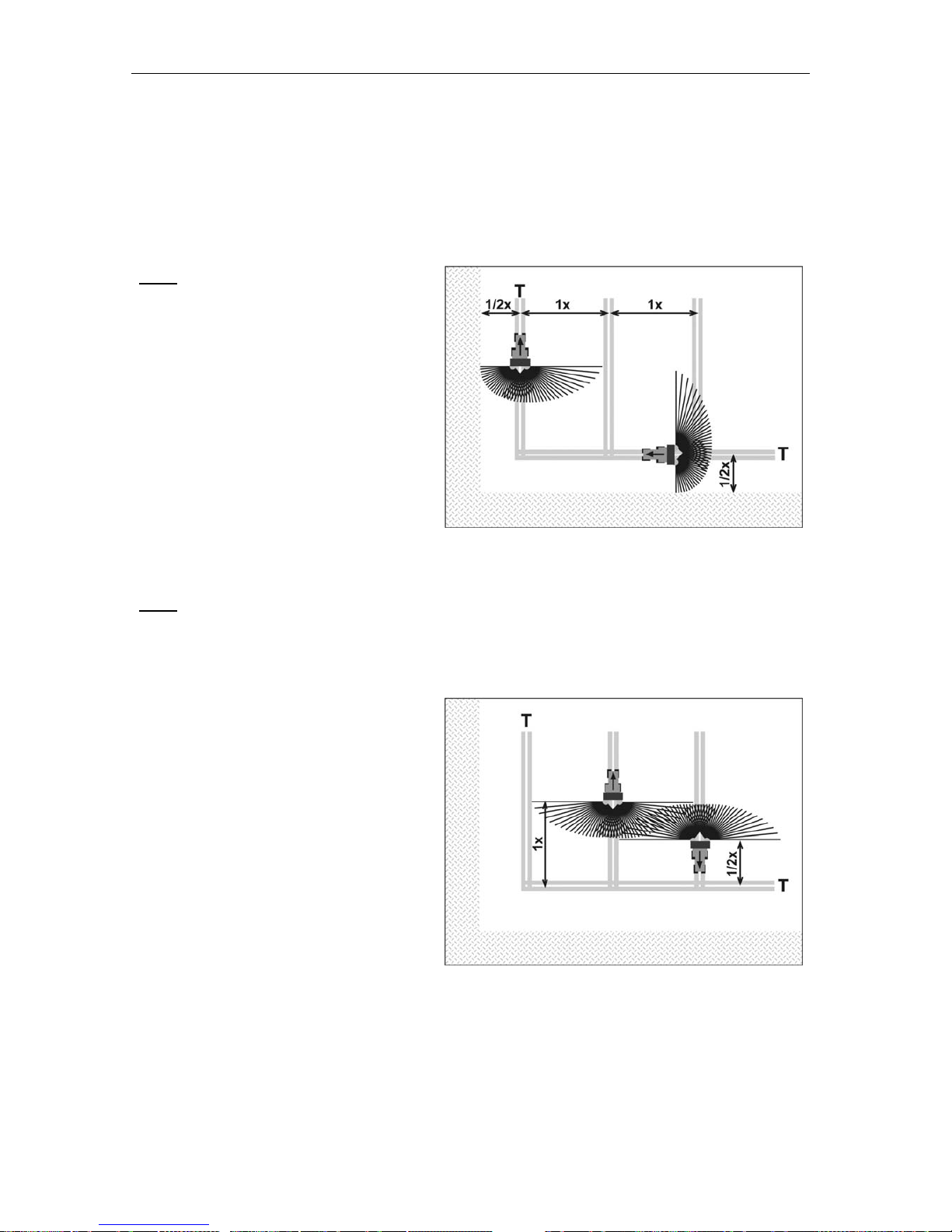
Erreur ! Style non défini. Erreur ! Style non défini.
67
10.1 Spreading procedure on headlands
To obtain optimal working results on headlands, it is essential that the tramlines are accurately positioned.
Fig. 1
When spreading at field edges with machines
equipped with the TELIMAT boundary spreading limiter, or when using a boundary
spreading disc, the first tramline (field edge
tramline (T)) must be positioned at exactly
half of the working width (x) away from the
field edge.
Additionally, a field edge tramline (T) should
be placed at the headland half of the working
width away from the field edge.
Fig. 2
When spreading within the field, make sure that after spreading from the field edge tramlines the
TELIMAT is pivoted out of the spreading flow and any boundary spreading discs are exchanged for
normal spreading discs.
The shutter slides are open and closed at different points from the field edge, depending
on the spreading direction.
When driving into the field, the shutter slides
should open about one working width (x) away from the field edge tramline (T) after
passing over it.
When driving out of the field, the shutter slides should be closed about half a working
width (x) away from the field edge tramline
(T) before passing over it.
Respecting this advice will achieve an economic, environmental-friendly result!
Page 70

Erreur ! Style non défini. Erreur ! Style non défini.
68
11 Fault diagnosis
11.1 Uneven spread pattern
Fertiliser build-up
• Remove fertiliser build-up around spreading discs, vanes and metering outlet tracts.
• Check that disc vane positions correctly correspond to the spreading charts.
Too much fertiliser within the tractor tracks
• Check that disc vanes are correctly positioned as per spreading charts.
• Check disc vanes and metering outlets for damage. Replace defective
parts immediately.
• Fertiliser granules have a smoother surface than those tested for the sprea-
ding chart (see section 6.6)
Too much fertiliser in overlapping zones
• Check that disc vanes are correctly positioned as per spreading charts.
• Fertiliser granules have a rougher surface that those tested for the calibrati-
on charts (see section 6.6).
• Pto speed is higher than what the tractor tachometer indicates. Check rpm.
Spreading application higher on one side than the other
• Check that metering slides are correctly balanced (see section. 8.5)
Fertiliser flow to spreading discs is uneven
• Check agitator and replace, if necessary.
• Fertiliser has formed a bridge over the metering outlet
Spreading discs are fluttering
• Check that synthetic castellated disc hub nuts are correctly tightened and
seated. Replace if defective.
With closed metering slides, fertiliser trickles out of the hopper
• Check the distance between the lower edge of the agitator finger and the
hopper floor. If it is more than 3mm the hopper must be shimmed between
hopper floor and frame.
11.2 Fault diagnoses for hydraulic metering controls
Hydraulic cylinder does not open
• Metering slides are too stiff. Check that slides, levers and pivot points are
free and adequately lubricated.
• Restrictors in the hydraulic circuits are dirty. Remove and clean.
Hydraulic cylinder opens too slowly
• Oil is not thin enough. Replace existing restrictor with a 1mm size restrictor.
The restrictor is situated in the input pressure hose connection on the cylinder. (With double acting cylinders in the cylinder base hose connecti-
ons.)
11.3 Disc vane wear
Some spreading products like Thomas Potash cause a higher wear rate on disc
vanes. Change worn disc vanes as per sections 9.2 and 9.3 "Replacing disc
vanes".
Page 71

Erreur ! Style non défini. Erreur ! Style non défini.
69
12 Optional equipment
12.1 Hopper extension sets
The hopper capacity of the spreader can be increased with the addition of an
extension set. Three- and four-sided extension sets with various capacities are
available for models MDS 735 and MDS 935 (see section. 4.1 "Technical Specification Data MDS"). The extension sets are bolted on to the basic unit.
12.2 Hopper cover
Spreading material can be protected against rain and humidity by the addition of
a hopper cover. Implements that are already equipped with extension sets can
also be fitted with a hopper cover.
Hopper covers can be folded back, as they are bolted to the hopper or to the
extension set with a foldable hinge bar.
12.3 Hopper sieve
Foreign particles or large solidified fertiliser lumps can be prevented from entering the hopper with the addition of a hopper sieve. This could avoid possible
damage to metering outlets and disc vane elements.
12.4 RFZ 7M (all MDS fertiliser spreaders except MDS 55)
This 7-row spreading unit is suitable for spreading dry prilled fertiliser in rows
next to existing crops.
The row spreading unit is supplied with its own instruction manual and assembly instructions.
12.5 Double acting mechanism
It is possible to operate the units on tractors equipped with only one control valve when a double acting mechanism is fitted to models MDS 735 K and MDS
935 K.
12.6 Tele-Space
The Tele-Space pto shaft allows additional free room (approx. 300mm) between
spreader and tractor, to facilitate easier attachment.
12.7 Practical Test Kit PtK
To check the spread pattern in the field.
12.8 Fertiliser identification system FiS
Quick and uncomplicated determination of correct spreader set-up for unknown
fertilisers.
Page 72

Erreur ! Style non défini. Erreur ! Style non défini.
70
12.9 Row spreading unit RV 2M for hopyards and orchards
The RV 2M row spreading unit is attached to the top yoke of the drawbar flange.
The RV 2M is designed so that row crops of 2 to 5 m can be covered with a 1m
wide spread band on both the left- and right-hand sides of the spreader. It is
recommended to set the disc vanes into position A1-A1, due to the narrow
spreading width.
Under no circumstances should the disc vanes be set higher than the C4 or D2
position, otherwise they will foul the row spreading unit.
As a precaution, turn the discs by hand after fitting the row spreading unit, to
make sure nothing fouls. Raising and lowering the unit will produce small variations in width settings available on the row spreading unit.
Spreading quantity can be proportionally calculated against effective spreading
width in the spreading chart.
Two rows are to be spread. The distance between the rows is 3m.
The effective working width is 6m. As the spreading charts do not give any data
for 6m, it is recommended to use the settings given for 12m working widths.
If an application rate of 200 Kg/ha in a 6m working width needs to be achieved,
take the settings indicated in the spreading charts for 12m and set the metering
slide position for 100 kg/ha, as the actual working width is 6m and not 12m.
12.10 Boundary spreading limiter GSE 7
Limiting the spreading width on either the left- or right-hand side between approx. 75cm and 2m from the middle of the tractor to the field edge, can be achieved. The metering slide nearest the field edge is closed. For boundary
spreading the unit is folded down. To return to normal full width spreading, the
boundary spreading limiter must be folded up.
12.11 Electronic remote control EF 24
Using the EF 24 electronic remote control unit, the boundary spreading limiter
GSE 7 can be electronically operated from the tractor cab, bringing it into boundary spreading mode and back to normal spreading mode.
12.12 Hydraulic remote control FHZ 10
Using the FHZ 10 hydraulic remote control unit, the boundary spreading limiter
GSE 7 can be hydraulically operated from the tractor cab, bringing it into boundary spreading mode and back to normal spreading mode.
How to do it!
Page 73

Erreur ! Style non défini. Erreur ! Style non défini.
71
12.13 Lighting without warning shield BLO1 (for rear profile
lighting security) for MDS 65 / MDS 85)
For safety reasons it is highly recomended that the fertiliser spreader is equipped with this lighting set.
12.14 Lighting without warning shield BLO2 (for rear profile
lighting security)
For safety reasons it is highly recommended that the fertiliser spreader is equipped with this lighting set.
12.15 Lighting with warning shield BLW 1 (for rear profile
lighting security) for MDS 65 / MDS 85
The rear of the fertiliser spreader profile must be equipped with warning and
lighting elements when the rear edge of the unit extends more than 1m from the
tractor running lights or when the side of the unit extends more than 40 cm outside the outermost illuminated edge of the running light.
The rear of the fertiliser spreader profile must likewise be equipped with warning
and lighting elements, if the unit covers the tractor lighting installations.
12.16 Lighting with warning shield BLW 8 (for rear profile
lighting security)
The rear of the fertiliser spreader profile must be equipped with warning and
lighting elements when the rear edge of the unit extends more than 1m from the
tractor running lights or when the side of the unit extends more than 40 cm outside the outermost illuminated edge of the running light.
The rear of the fertiliser spreader profile must likewise be equipped with warning
and lighting elements, if the unit covers the tractor lighting installations.
12.17 TELIMAT T1
For remote controlled yield and enviromental optimised border spreading.
12.18 Hydraulic metering slide control FHK 4
(Single acting cylinder) for MDS 55M / 65M / 85M / 735M / 935M.
12.19 Hydraulic metering slide control FHD 4
(Double acting cylinder) for MDS 55M / 65M / 85M / 735M / 935M.
12.20 Agitator for grass seeds RWK 7
12.21 Agitator RWK 15
For powdery fertiliser.
Page 74

Erreur ! Style non défini. Erreur ! Style non défini.
72
13 Axle load calculation
IMPORTANT
Overload danger
When fitting front or rear mounted implements, the total permissible weight, axle loading and tyre loads of the tractor must not be exceeded. The front axle must exert
a ground load of at least 20% of the unloaded weight of the tractor.
To judge if axle loadings are correct, use the following calculation methods or
weigh the tractor/implement combination before using any implement.
Determining the total weight, axle and
tyre loadings, as well as the necessary
ballast weights.
The following data is needed for calculation
TL [kg] Tractor weight (unladen)
(1)
T
V
[kg] Front axle load of unladen tractor
(1)
T
H
[kg] Rear axle load of unladen tractor
(1)
G
H
[kg] Total weight of rear implement/rear ballast
(2)
G
V
[kg] Total weight of front implement/front ballast
(2)
a [m] Distance between front implement/ballast centre of gravity and centre of front axle
(2) (3)
b [m] Tractor wheel base
(1) (3)
c [m] Distance between centre of rear axle and centre of lower link ball joint
(1) (3)
d [m]
Distance between centre of lower ball joint and rear implement/ballast centre of
gravity
(2)
(1) See tractor operator manual
(2) See price list and/or implement operator manual
(3) Measure
Page 75

Erreur ! Style non défini. Erreur ! Style non défini.
73
Rear and front/rear mounted combination
CALCULATING THE MINIMUM FRONT
BALLAST NEEDED G
V min
ba
bT2,0bT)dc(G
G
LVH
min
V
+
••+•−+•
=
Insert this minimum front tractor ballast value in the table overleaf.
Front mounted implements
CALCULATING THE MINIMUM REAR
BALLAST NEEDED G
H min
dcb
bT45,0bTaG
G
LHV
min
H
++
••+•−•
=
Insert this minimum rear tractor ballast value in the table overleaf.
(If the front mounted implement (GV) is lighter than the minimum front ballast (G
V min
), the wieght of the
front implement must be increased to the minimum required front ballast weight!)
CALCULATING THE ACTUAL FRONT AXLE
LOAD T
V tat
b
)dc(GbT)ba(G
T
HVV
tat
V
+•−•++•
=
Insert this actual front axle load value and the permissible front axle load, as given in the tractor operator manual, in the table overleaf.
(If the rear mounted implement (GH) is lighter than the minimum rear ballast (G
H min
), the weight of the
rear implement must be increased to the minimum required rear ballast weight!)
CALCULATING THE ACTUAL TOTAL WEIGHT
G
tat
HLVtat
GTGG ++
=
Insert this actual total weight value and the permissible total weight, as given in the tractor manual, in
the table overleaf.
CALCULATING THE ACTUAL REAR AXLE
LOAD T
H tat
tatV
tat
tatH
TGT −=
Insert this actual rear axle load and the permissible rear axle load, as given in the tractor manual, in
the table overleaf.
PERMISSIBLE TYRE LOADS
Insert the permissible tyre load x two (two tyres) (see tyre manufacturer's information) in the table overleaf.
Page 76

Erreur ! Style non défini. Erreur ! Style non défini.
74
TABLE
Actual calculated
values
Permissible values
as per operator
manual
Maximum permis-
sible tyre load x two
(2 tyres)
Minimum front/rear
ballast
/
Kg
≤
Total weight
Kg
≤
Kg
Front axle
Kg
≤
Kg
≤
Kg
Rear axle
Kg
≤
Kg
≤
Kg
The minimum ballast must be achieved by attaching either implements and/or ballast weights
to the tractor!
The calculated values must be smaller than or equal to the permissible values!
Page 77

LIMITED WARRANTY
KUHN S.A. of 4 Impasse des Fabriques, 67706 SAVERNE CEDEX, France (hereinafter called the
«Company») warrants, in accordance with the provisions below, to each original retail purchaser of
KUHN new equipment of its own manufacture, from an authorized KUHN dealer, that such equipment
is, at the time of delivery to such purchaser, free from defects in material and workmanship and that
such equipment will be warranted for a period of one year starting from the date the goods are delivered
to the end user and during this period up to a limit of 500 hours use, providing the machine is used and
serviced in accordance with the recommendations in the Operator’s Manual.
THESE CONDITIONS ARE SUBJECT TO THE FOLLOWING EXCEPTIONS :
1. Parts of machines which are not of our manufacture i.e. tyres, belts, P.T.O. shafts, clutches etc., are not
covered by this Limited Warranty but are subject to the warranty of the original manufacturer. Any claim
falling into this category will be taken up with the manufacturer concerned.
2. Warranty claims applying to these types of parts must be handled in the same way as if they were parts
manufactured by KUHN. However, compensation will be paid in accordance with the warranty agreement of the manufacturer concerned in as much as the latter justifies such a claim.
3. This Limited Warranty will be withdrawn if any equipment has been used for purposes other than for
which it was intended or if it has been misused, neglected or damaged by accident or let out on hire. Nor
can claims be accepted if parts other than those manufactured by us have been incorporated in any of
our equipment. Furthermore, the Company shall not be responsible for damage in transit or handling by
any common carrier and under no circumstances within or without the warranty period will the Company
be liable for damages for loss of use or damages resulting from delay or any consequential damage.
We cannot be held responsible for loss of earnings caused by a breakdown or for injuries either to the owner
or to a third party, nor can we be called upon to be responsible for labor charges, other than originally
agreed, incurred in the removal or replacements of components.
THE CUSTOMER WILL BE RESPONSIBLE FOR AND BEAR THE COSTS OF:
1. Normal maintenance such as greasing, maintenance of oil levels, minor adjustments, etc.
2. Transportation of any kind of any KUHN product to and from the place the warranty work is performed.
3. Dealer travel time to and from the machine or to deliver and return the machine from the workshop for
repair.
4. Dealer travelling costs.
Parts defined as normal wearing items are listed as follows and are not in any way covered under this
Limited Warranty :
V belts, discs, knives, wear plates, disc guards, tires, torque limiters, hydraulic hoses, pitman shafts, swath
sticks, blades, tines and tine holders.
KUHN Limited Warranty will not apply to any product which is altered or modified without the expressed
permission of the Company and/or repaired by anyone other than Authorized Service Distributors or
Authorized Service Dealers.
Page 78

LIMITED WARRANTY IS DEPENDENT UPON THE STRICT OBSERVANCE BY THE
PURCHASER OF THE FOLLOWING PROVISIONS :
- That this Limited Warranty shall not be assigned or transferred to anyone unless the Comp any’s consent in
writing has first been obtained.
- The warranty/product registration form has been correctly completed by dealer and purchaser with their
names and addresses, dated, signed and returned to the appropriate address as given on the warranty/
product registration form.
- The claim form sent to KUHN has been correctly completed stating:
* dealer’s name and address
* owner’s name and address
* type of machine
* machine serial number
* delivery date to buyer
* date of failure
* tractor make and type
* description of the failure and its cause
* quantity, reference number and name of the damaged part s
* reference number , quantity and date of the invoice for the replacement p arts.
- The judgement of the Company in all cases of claims under this Limited W arranty shall be final and conclu-
sive and the purchaser agrees to accept its decisions on all questions as to defect and to the exchange of
any part or parts.
- That all safety instructions in the Operator’s Manual shall be followed and all safety guards regularly inspected
and replaced where necessary .
No warranty is given on second-hand products and none is to be implied. Persons dealing in the Company’s
products are in no way legal agents of the Company and have no right or authority to assume any obligation
on their behalf, express implied, or to bind them in any way .
KUHN S.A. reserves the right to incorporate any change in design in its products without obligation to make
such changes on units previously manufactured.
Moreover, because of the constant progress in technology, no guarantee is given to the descriptions of
equipment published in any document by the company .
DISCLAIMER OF FURTHER W ARRANTY
There are no warranties, expressed or implied, except as set forth above. There is no
warranty of merchantability. There are no warranties which extend beyond the description
of the product contained herein. In no event shall the company be liable for indirect, special
or consequential damages (such as loss of anticipated profits) in connection with the retail
purchaser’s use of the product.
Page 79

- N O T E S -
Page 80

This machine complies with the safety requirements of the European machinery directive.
The Operator should respect all Health and Safety regulations as well as the Highway
Code. For your own safety, use only genuine KUHN spare parts. The manufacturer
disclaims all responsibilities due to incorrect use or non-compliance with the
recommendations given in this manual.
Page 81

Printed in France by KUHN
KUHN S.A. 4 Impasse des Fabriques F - 67706 SAVERNE CEDEX (FRANCE)
Tél. : + 33 (0) 3 88 01 81 00 - Fax : + 33 (0) 3 88 01 81 03
www.kuhnsa.com - E-mail : info@kuhnsa.com
Société Anonyme au Capital de 19 488 000 Euros
For your safety
and to get the best from your machine,
use only genuine KUHN parts
 Loading...