

Page 1

OPERA TOR'S MANUAL
MDC
Application rate monitoring
system
No 95738 B.GB - 01. 2005
for VENTA
Page 2

DEAR OWNER,
In buying a KUHN machine you have chosen wisely. Into it have gone years of thought,
research and improvements. You will find, as have thousands of owners all over the world, that
you have the best that engineering skill and actual field testing can produce. You have
purchased a dependable machine, but only by proper care and operation can you expect to
receive the performance and long service built into it.
This manual contains all the necessary information for you to receive full efficiency from your
machine. The performance you get from this machine is largely dependant upon how well you
read and understand this manual and apply this knowledge. Please DO NOT ASSUME THAT
YOU KNOW HOW TO OPERATE AND MAINTAIN YOUR MACHINE before reading this
manual carefully. KEEP THIS MANUAL AVAILABLE FOR REFERENCE.
Your KUHN dealer will instruct you on the general operation of your machine. He is interested
that you get the best performance possible and will be glad to answer any special questions
that may arise regarding the operation of the KUHN machine.
Your KUHN dealer can offer a complete line of genuine KUHN service parts.
These parts are manufactured and carefully inspected in the same factory that builds the
machine to assure high quality and accurate fitting of any necessary replacements.
When ordering service parts it is important that you indicate the type of machine concerned
and its serial number.
For this reason please complete the model identification plate diagram below with the required
information. This will provide you with an easy reference for future service parts orders.
ABOUT IMPROVEMENTS
KUHN is continually striving to improve its products and, therefore, reserves the right to make
improvements or changes when it becomes practical to do so, without incurring any
obligations to make changes or additions to the equipment sold previously.
Page 3

TABLE of CONTENTS
A Description............................................................................................................. 3
B Summary of use .................................................................................................... 4
C Detailed description of the system...................................................................... 6
C 1 Electric power supply................................................................................... 6
C 2 Design.......................................................................................................... 6
D Work and display settings ................................................................................... 8
D 1 Setting the point of reference ...................................................................... 8
D 2 Opening calibration (flow control)................................................................. 9
D 2.1 Setting the seed type........................................................................9
D 2.2 Setting the opening......................................................................... 10
D 2.3 Flow control ................................................................................... 10
D 3 Programming the nominal application rate (100% )...................................11
D 4 Adjustment to the nominal application rate (100%).................................... 12
D 5 Setting the application rate adjustment level.............................................. 12
D 6 Application rate adjustment in %................................................................ 12
D 7 Setting the null flow rate ............................................................................ 13
E Connection to a « Master » terminal (GPS mode)
E 1 Description................................................................................................. 14
E 2 Work and display settings..........................................................................15
F System adjustment and calibration .................................................................. 16
F 1 Adjusting the opening pulses......................................................................16
F 2 Adjustment of the opening limit points........................................................17
F 3 Screen test................................................................................................. 18
F 4 Rotation sensor test ................................................................................... 18
F 5 Motor and sensor pulse test....................................................................... 18
F 6 Setting the maximum amperage................................................................. 19
F 7 Setting the maximum functioning time under maximum amperage............ 19
G Trouble shooting guide ..................................................................................... 20
H Symbols ............................................................................................................. 21
2
Page 4
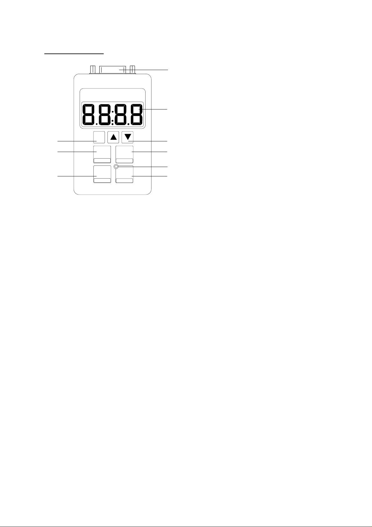
A Description
9
1 – Screen
2 – « Arrow » keys
F
CAL
SP
kg / ha
2 « Arrow » keys
3 « Function » key
MDC
+
STEP %
-100%
REF
1
3 – « Function » key
4 – « Plus » key
5 – « Flow control » key
23
45
6
78
?? Modification of the value.
?? Sets system by pressing this key when switching
on.
?? Second function of keys when pressing this key
simultaneously.
?? Store the selected function by pressing and
holding
6 – « Movement » display
7 – « Minus » key
8 – « 100% application rate » key
9 – Standard connection socket
4 « Plus » key
5 « Flow control » key
6 « Movement » display
7 « Minus » key
8 « 100% application rate » key
?? Increase in % of the application rate.
?? Setting the application rate monitoring level (dual
function key).
?? Setting the seed type (small or large seeds).
?? Programming the opening for carrying out a flow
control .
?? Setting the null flow rate (dual function key).
?? LED lights when metering unit rotates.
?? Reduction in % of the application rate.
?? Setting the point of reference (double function).
?? Adjustment to the nominal application rate
(100%)
?? Programming the application rate (dual function
key)
3
Page 5
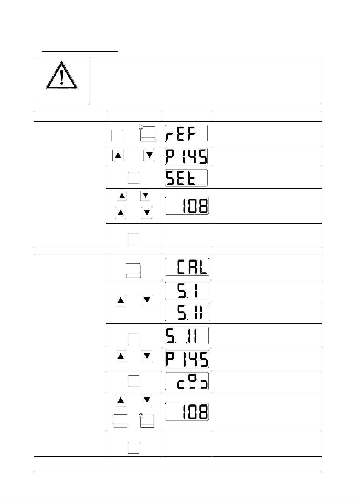
B Summary of use
When moving the metering unit by more than 30 mm, rotate metering
unit to avoid crushing seeds !
IMPORTANT
Action
Checking the opening position
(task to carry out at
work begin, in case
of seed change, at
least once per day)
When seeding in « small seed » position, the control box must also be
set on the « small seed » position!
Control Screen Result
Automatically goes to next screen
after 2 seconds
Metering unit moves to the required
opening
Automatically goes to next screen
after 2 seconds
F
and
and
F
-
REF
Calibration of the
seed type
Setting the opening
(flow control)
or
or
3 seconds
F
3 seconds
CAL
SP
or
3 seconds
F
or
Setting an opening position
Storing the opening
Automatically goes to next screen
after 2 seconds
Setting « small seeds »
Setting « large seeds »
Storing the choice of seed type
Setting the metering opening according to chart
F
or
or
F
-
REF
4
+
STEP %
3 seconds
Programming the nominal application rate /ha !
Automatically goes to next screen
after 2 seconds
Entering weight in kg/ha
Storing the collected weight
Page 6
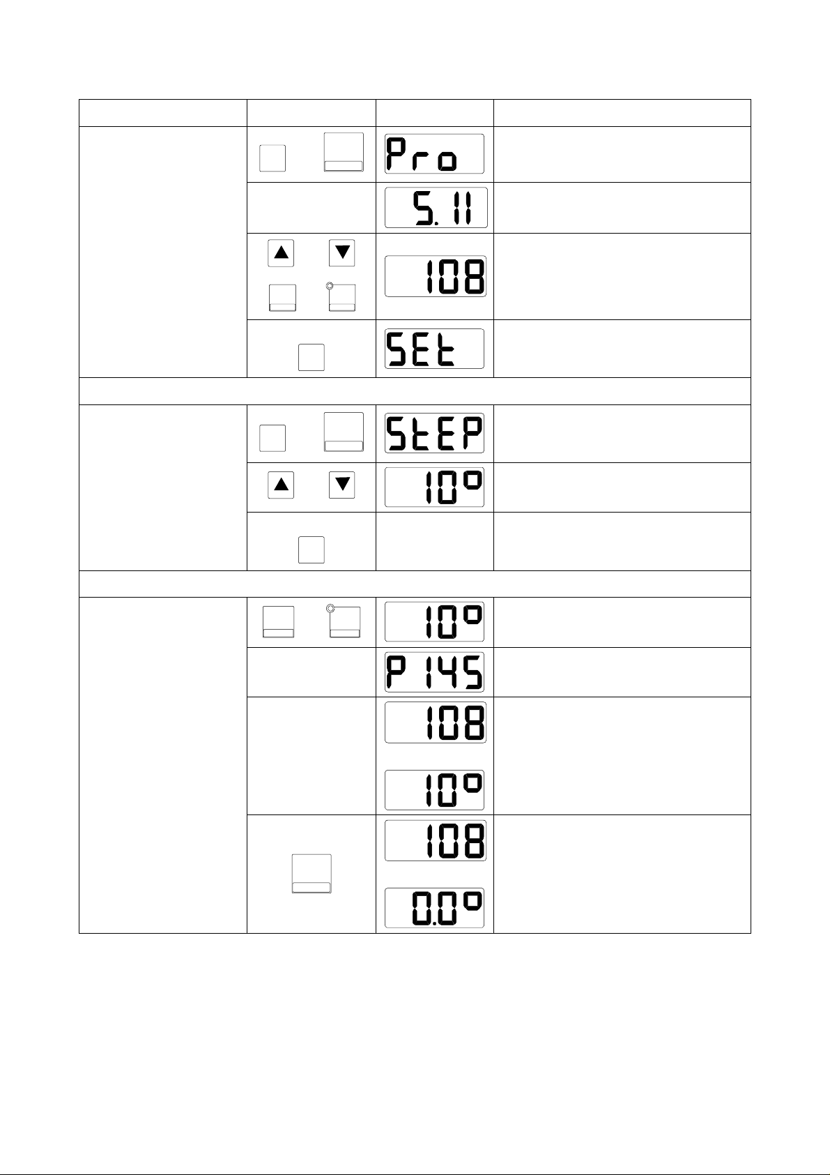
Action
Setting the nominal
application rate /ha
(100%)
Control Screen Result
Automatically goes to next screen
after 2 seconds
Automatically goes to next screen
after 2 seconds
F
and
100%
kg / ha
Setting the application rate monitoring
level
Adjustment of the
application rate (in
%)
+
STEP %
3 seconds
F
3 seconds
+
STEP %
or
-
REF
ou
F
+
STEP %
and
or
F
-
REF
or
Setting the nominal application rate
(100 %) in kg/ha
Storing the nominal application rate
Automatically goes to next screen
after 2 seconds
Adjustment of the level to
5%, 10% or 15%
Storing the monitoring level
The application rate is adjusted of
the displayed level (max. ? 60%)
The metering unit position is displayed for 2 seconds
The adjusted application rate and
100%
kg / ha
alternately
alternately
the adjustment level are displayed
alternately.
Setting the nominal application rate
5
Page 7
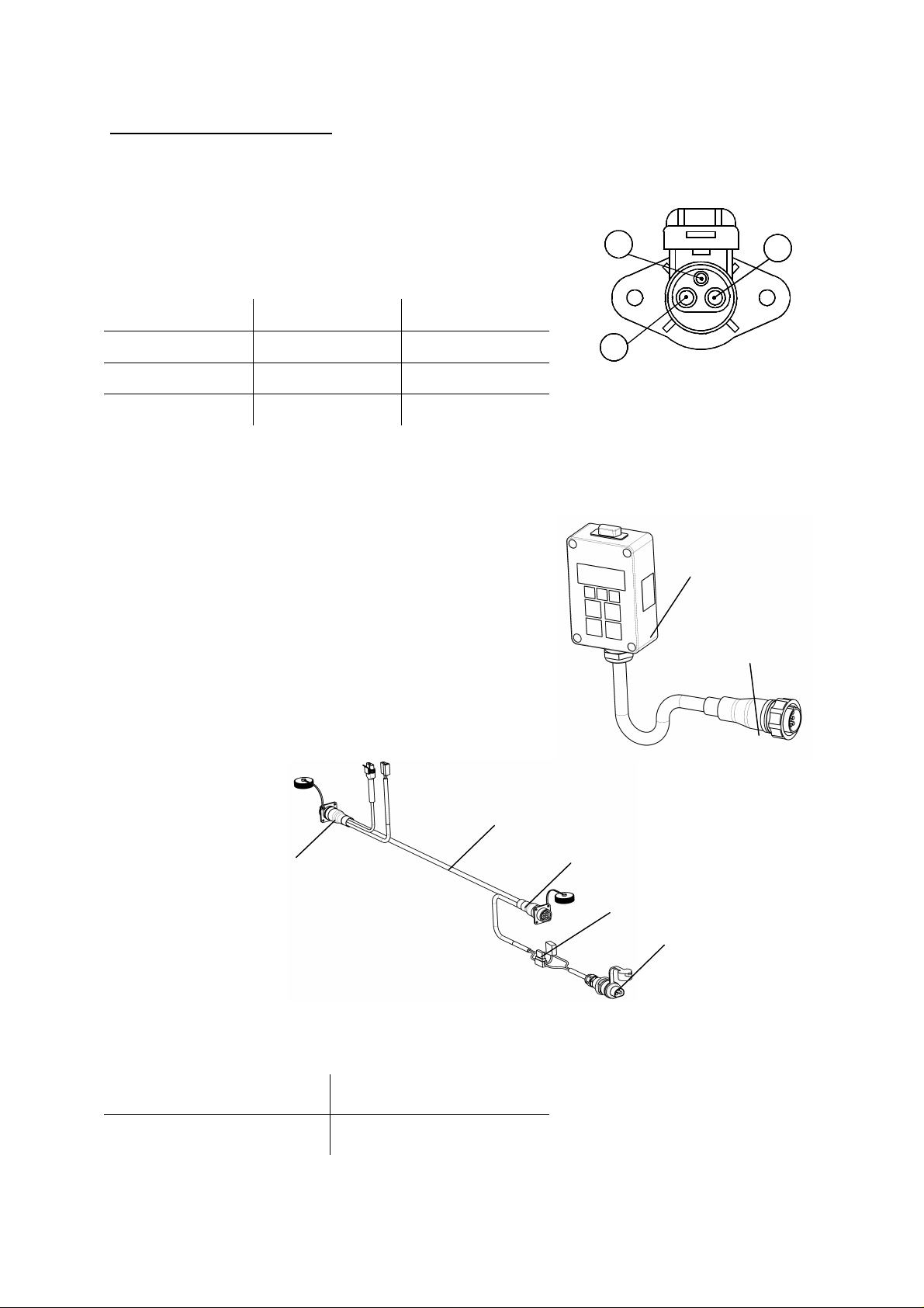
The MDC control box is supplied by a 3 pin plug
O 12369) connection onto the tractor
posed
tween
the tractor and the machine, a sensor and a driving
pin
pin plug (5) if
ctric power supply is
3 2 4 5 6
7
C System description
C 1 Electric power supply
(DIN 9680, IS
network
Pin number Wire colour Function
15 / 30 Brown + 12 Volt
31 Blue Mass
81 - Not used
C 2 Design
The MDC electronic monitoring system is com
of a control box (1), a wiring harness (2) be
motor.
The MDC control box is connected either by its 9-
plug (3) in the cabin to the 9-pin plug (4) of the wiring harness connector or on the 9moved to the machine. The ele
made through plug (6).
The control box is protected by a fuse of 15 A (7).
1
15/30
31
82
2
3
1
Recommended distance of sensor (with regards
to the notched wheel metal stud)
Sensor Distance
From motor position 0,4 – 0,8 mm
6
Page 8
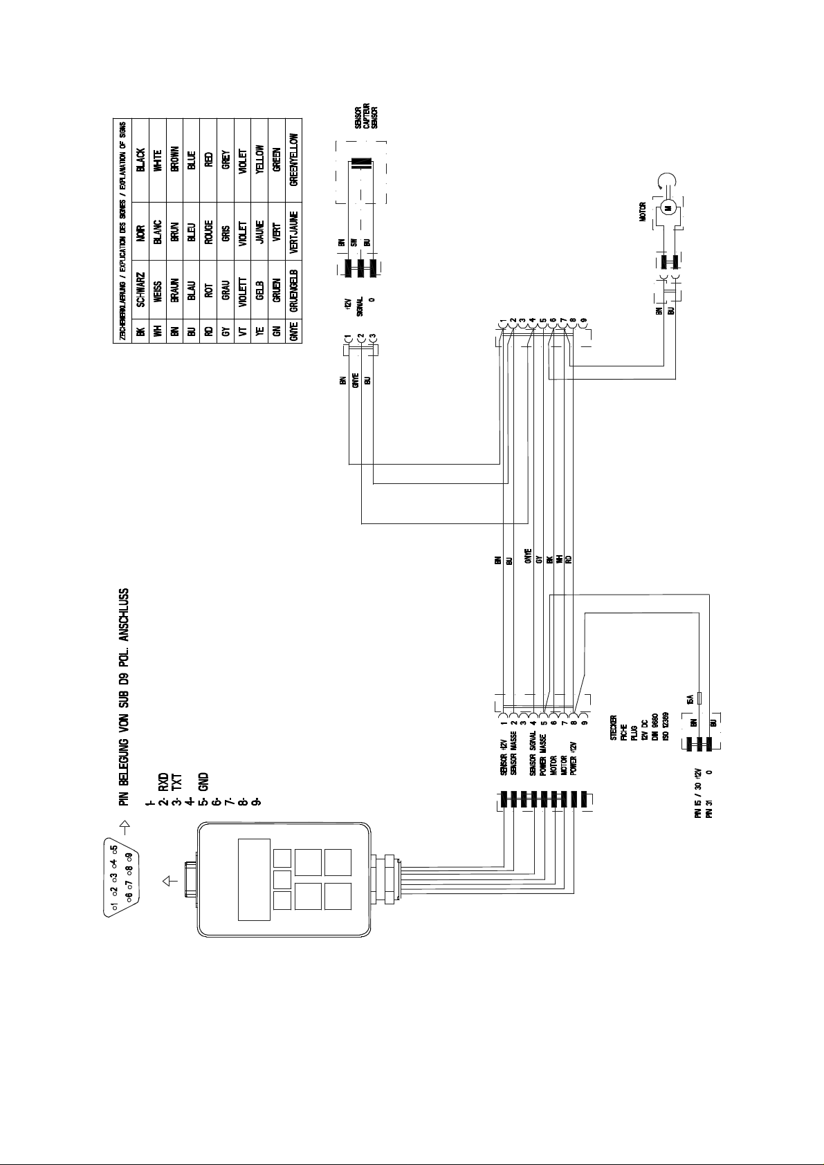
VENTA MDC connection plan
7
Page 9
D Work and display settings
The following settings and displays are vital (bold) or can be made in view of the work to
carry out :
1) Setting the point of reference
2) Calibration of the opening (flow control)
3) Programming the nominal seed application rate (100%)
4) Adjusting the metering unit to the nominal seed application rate
5) Programming the seed application rate adjustment level
6) Distribution adjustment of the chosen seed application rate
7) Setting the null flow rate (in case of maintenance)
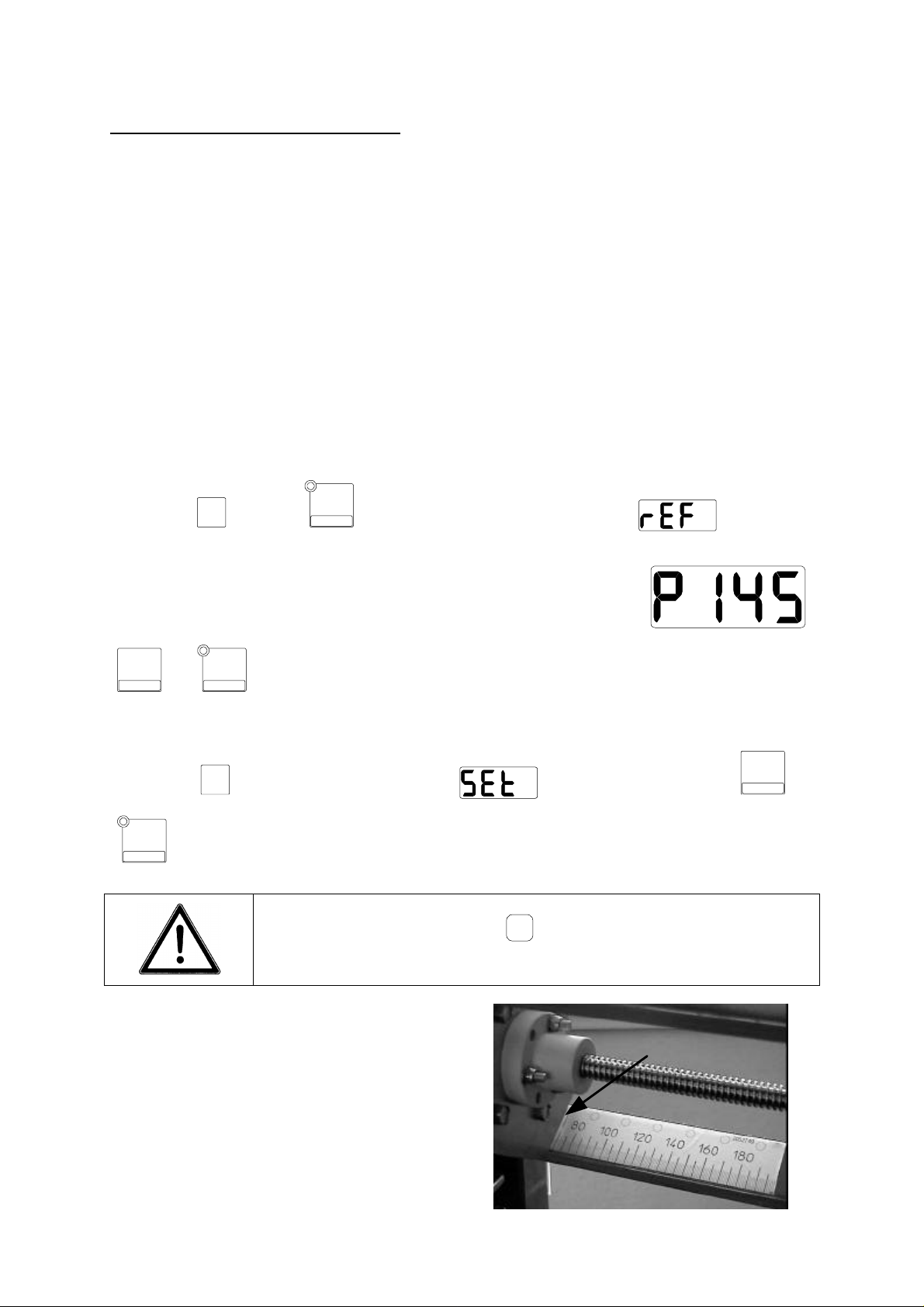
D 1 Setting the point of reference
Should their be a power cut during a motor manoeuvre or due to its removal, the point of
reference must be newly calibrated.
It must be checked at work begin, when changing the seed type or at least once a day!
Press key
The screen displays the theoretical point of reference: it must be
adjusted to an identical position corresponding to the current real
opening position of the metering unit.
+
STEP %
or
easier reading of the graduation). This manoeuvre is not compulsory !
and key
-
REF
keys enable changing the metering unit opening position (for ex. : for an
F
-
REF
to recalibrate the point of reference:
F
Press key
-
REF
to obtain the required value.
: the screen briefly displays . Now, modify with keys
Store this value by pressing
flashes briefly!
F
key for 3 seconds until the display
+
STEP %
or
1
1) Metering unit position (ex. : 70)
8
Page 10

D 2 Calibration of the opening (flow control)
CAL
Press for approx. 3 seconds key
(selection of the seed type, choice of opening for the flow control).
For seeding with the metering unit in « small seed » position
(rapeseed, clover, rye-grass,… i.e. with metering unit reduc-
SP
to carry out calibration for the flow control
tion slide engaged), the MDC must also be set on « small
seed » position if you do not want to risk damaging the me-
IMPORTANT
tering unit during work !
D 2.1 Setting the seed type
Use keys to select the seed type:
Small seed (clover, rapeseed, grass, etc.)
Large seed (wheat, barley, peas, horse beans, etc,)
Store this value by pressing
play flashes briefly!
F
key for 3 seconds until the dis-
The type of seeds memorized is briefly displayed on the screen:
Small seed (clover, rapeseed, grass, etc.)
Large seed (wheat, barley, peas, horse beans, etc,)
9
Page 11

the
D 2.2 Setting the opening
The current value of the metering unit position is displayed:
Opening position
Select from the adjustment chart the required opening in order to carry out a flow
control. It depends of the seed type and the required application rate (ex. : rate required in wheat 180 kg/ha, opening position at 90).
-
REF
to reach the desired opening position.
Use key
IMPORTANT
Press key
+
STEP %
or key
When moving the metering unit by more than 30 mm, rotate
F
metering unit to avoid crushing seeds !
to go onto the next step.
D 2.3 Flow control
After having selected the opening and pressed on key
screen briefly displays the scale symbol :
You may now carry out the flow control (see seed drill operator’s manual).
Weigh the quantity collected during test, convert it in kg/ha and enter it using
F
keys .
Store this value by pressing
play flashes briefly!
10
F
key for 3 seconds until the dis-
Page 12

The nominal seed application rate must now be programmed by pressing on key
100%
F
and at the same time briefly on key
NOTE : An alarm is displayed if the metering unit opening limits are reached when
setting the nominal application rate. The desired value cannot be reached, the screen
shows alternately the obtained seed application rate and the corresponding adjustment level.
kg / ha
.
D 3 Programming the nominal application rate (100%)
To programme the nominal application rate (i.e. the average value or 100%) press
100%
key
F
together with key
kg / ha
. The screen briefly displays
+
Use keys or
application rate in kg/ha.
Example of nominal seed application rate in kg/ha
Note: a message appears if the metering unit opening limits are reached when programming the application rate, the maximum seed application rate which can be
reached will be displayed.
Alarm Point of Limit « small seed » reached
STEP %
or keys or
Store this value by pressing
stored when the display shows before switching to the
work screen!
-
REF
to display the desired nominal
F
key for 3 seconds, the value is
Alarm Point of Limit « large seed » reached
11
Page 13

tion that the metering unit opening limit is not reached.
D 4 Adjustment to the nominal application rate (100%)
100%
Press key
kg / ha
to adjust the metering unit opening to the nominal application rate.
D 5 Setting the application rate monitoring level
The monitoring level in % can be adjusted by pressing key
+
STEP %
key
Use keys
15%.
.
+
STEP %
-
and
REF
to choose the adjustment level in steps of 5%, 10% or
Store this value by pressing
play flashes briefly!
F
key for 3 seconds until the dis-
D 6 Adjustment in % of the application rate at work
+
Use keys
application rate.
STEP %
or
-
REF
to adjust the nominal seed application rate to a different
F
together with
The display alternately shows the application rate reached and
the current adjustment level :
The maximum seed application rate adjustment range is ± 60%
on condi
An alarm appears if the opening limits are reached, the maximum seed application
rate which can be reached and the corresponding adjustment level will show alternately.
Alarm Point of Limit « small seed » reached
Alarm Point of Limit « large seed » reached
12
Page 14

This programming must imperatively be made for SP1 and
D 7 Setting the null flow rate:
This adjustment is specific to the seed drill type (mechanical or pneumatic) and is
only to be carried out when fitting the equipment or should the MDC control box
be replaced.
The calibrations of the null flow rate (in small or large seeds) is carried out by press-
CAL
SP
.
ing simultaneously on keys
F
and
F
Use keys to choose the one to programme. Press key
+
or
Value of the null flow rate in « small
seeds » for VENTA seed drills
Value of the null flow rate in « large
seeds » for VENTA seed drills
STEP %
-
REF
to modify these values.
??
SP2.
and use keys
?? Store this value by pressing
the display flashes briefly!
F
key for 3 seconds until
13
Page 15

E Connections with a « MASTER » terminal (GPS mode)
The standard connection plug enables connecting the MDC control box to a terminal.
This link enables monitoring the application rate within the field (Precision Farming).
The GPS positioning and the corresponding application rate are transmitted by the
« master » terminal to the MDC control box.
Depending on the « master » terminal, the MDC control box will transmit in return
information on the work achieved, to the « master » terminal. Information on the use
of the « master » terminal is indicated in its operator’s manual.
E 1 Description
Following terminals, fitted with a standard RS232 plug, can be connected using a
cable 0 Modem Sub D9 (female/female) for connection to the MDC control box. The
wiring plan in the cable can be checked at point C2.
PRO SERIES
(RDS)
(AGROTRONIX)
FIELD
OPERATOR
(WTK)
ACT
(MÜLLER /
CLAAS)
cable 0 Modem Sub D9 (fe-
male/female)
MDC Control box
FIELDSTAR
(AGCO)
14
Page 16

E 2 Work and display settings
Prior to connecting the terminal and the MDC control box, select the connection
protocol in the « master » terminal.
This protocol is in one way the « language » which will enable communication between both control boxes. Refer to the « master » terminal operator’s manual to adjust this selection.
« Master » Terminal Connection protocol
PRO SERIES 8000 (RDS) Modus B, FIELDSTAR
AGRO PILOT (AGROTRONIX) MDC
FIELD OPERATOR (WTK) FIELDSTAR
ACT 2-40 (MÜLLER / CLAAS) LH AGRO
FIELDSTAR (AGCO) FIELDSTAR
The MDC monitoring must be calibrated prior to the connection with the « master »
terminal, see points D1 to D7 in this manual.
The MDC control box keys are secured and are therefore inaccessible when working
in GPS mode.
If the connection is properly made between both control boxes,
the display shows the symbol opposite. Furthermore the LED
light flashes on the control box.
When switching off the « master » terminal, removing the connection cable or if there is a connection breakdown between
the 2 control boxes, the MDC control box screen displays the
symbol opposite after 10 seconds. The LED light is off.
The LED light is on without flashing if the « master » terminal modifies the application
rate and the motor adjusts the opening.
15
Page 17

Note: a message appears if the metering unit opening limits are reached when adjusting the seed application rate, the rate planned in GPS cannot be reached.
Alarm Point of Limit « small seed » reached
Alarm Point of Limit « large seed » reached
F System adjustment and calibration
Adjustments relative to the system’s good functioning can be accessed by pressing
key
can be checked and modified if necessary:
To go onto the next point to check/modify, press key
To leave this menu, press any other key.
To adjust the amperage limit, simultaneously press key and activate the control
box (12 V).
To adjust the maximum functioning time under maximum amperage, simultaneously
F
and simultaneously placing it under a 12 Volt tension. Following parameters
1) Opening pulses
2) Opening limit points
3) Checking the display screen
4) Checking the sensor
5) Checking the motor and pulses
Store these values by pressing
display flashes briefly!
F
key for 3 seconds until the
F
.
press key and activate control box (12V).
F 1 Adjusting the opening pulses
Use keys and to modify the displayed values:
16
Page 18

Adjustment for VENTA seed drills : 100 (100 pulses from the
impulse wheel with 30 teeth for a 10 mm metering unit movement)
Store these values by pressing
To go onto the next point to check/modify, press key
To leave this menu, press any other key.
display flashes briefly!
F
key for 3 seconds until the
F
.
F2 Adjustment of opening limit points
The maximum opening values of the metering unit must be programmed for the
« small seed » and « large seed » position.
+
Use keys or
the metering unit limit points according to the metering unit position. To go onto the
next screen, press key
STEP %
F
.
-
REF
to modify the displayed values corresponding to
Position (for VENTA) Display Required value
Minimum position
Position of limit « small
seed »
Position of limit « large
seed »
Store these values by pressing
To go onto the next point to check/modify, press key
To leave this menu, press any other key.
display flashes briefly!
F
key for 3 seconds until the
F
.
17
Page 19

F 3 Screen test
Press key
limit points to check the proper functioning of the screen
F
for 2 seconds after having adjusted the opening
F 4 Rotation sensor test
This test is automatically activated after the screen test. Check if the display changes
when metal passes in front of the sensor:
Sensor Display
Sensor deactivated
Sensor activated
To go onto the next point to check/modify, press key
To leave this menu, press any other key.
F
.
F 5 Motor test and sensor pulse count
+
Press keys
The number of pulses is displayed on the screen: it must increase or decrease according to the metering unit movement.
When moving the metering unit, pay attention to the pulse count. If the display
does not change: check the sensor/tooth wheel distance (0,4 to 0,8 mm) and
the sensor connection.
STEP %
and
-
REF
to open or shut the metering unit splines.
To go onto the next point to check/modify, press key
To leave this menu, press any other key.
18
F
.
Page 20

F6 Setting the maximum authorized amperage
To adjust the amperage limit, simultaneously press key and activate the control
box (12 V).
The keys now enable modifying the value indicated on the screen:
Adjustment for VENTA : 6A
Store this value by pressing
play flashes briefly!
F
key for 3 seconds until the dis-
F7 Adjustment of maximum functioning time under maximum a mperage
To adjust the maximum functioning time under maximum amperage, simultaneously
press key and activate control box (12V).
The keys maximum functioning time under maximum amperage:
Adjustment required for VENTA : 1.0 (1.0 second maximum
amperage)
Store this value by pressing
play flashes briefly!
19
F
key for 3 seconds until the dis-
Page 21

G Trouble shooting guide
Display Description of the incident or default
Closed position of the metering unit reached
“small seed” Opening limit position reached
“large seed” Opening limit position reached
Maximum functioning time under maximum amperage rea-
ched.
The motor must have reached an opening position stop.
The point of reference must be calibrated (see point D1).
The motor is perhaps jammed due to a foreign body:
check the metering unit, the point of reference must be
calibrated (see point D1).
No sensor signals although the 12 V motor rotates.
Check sensor: attachment, distance to the tooth wheel
(distance 0.4 – 0.8 mm). The point of reference must be
calibrated (see point D1).
The sensor is damaged: replace it and calibrate the point
of reference (see point D1).
In case of a control box defect, the hood covering the gearwheels which connect the
motor to the metering unit can be removed. Then turn gearwheel by hand to obtain
the desired metering unit opening.
After repair and depending on the part replaced, check all
parameters described in points F6, F7, F1, F2, F3, F4 , F5
IMPORTANT
and then D1 (calibration of the point of reference). !
20
Page 22

H Symbols
When activating functions or in case of incidents, the following symbols may appear :
below a summary of their signification :
Symbols Signification
Metering unit position : 145
Adjustment percentage applied : – 10%
Adjustment of opening pulses
Adjustment of the shutting point of limit
Adjustment of the « small seed » opening point of limit
Adjustment of the « large seed » opening point of limit
Sensor and motor test
Start of the flow control menu
Small seed setting
Large seed setting
Memorizing the « small seed » setting
Memorizing the « large seed » setting
Setting the « small seed » null flow rate
Setting the « large seed » null flow rate
Prior to memorizing the weight collected during test
Memorizing the nominal application rate
21
Page 23

Setting the point of reference
Memorizing the nominal application rate
Functioning time under maximum amperage reached
No signal from sensor
Connection with GPS terminal
Connection defect with the GPS terminal
Setting the maximum authorized amperage (6 amperes)
Adjustment of the maximum functioning time under maximum
amperage (1 second)
22
Page 24

LIMITED WARRANTY
KUHN S.A. of 4 Impasse des Fabriques, 67706 SAVERNE CEDEX, France (hereinafter called the
«Company») warrants, in accordance with the provisions below, to each original retail purchaser of
KUHN new equipment of its own manufacture, from an authorized KUHN dealer, that such equipment
is, at the time of delivery to such purchaser, free from defects in material and workmanship and that
such equipment will be warranted for a period of one year starting from the date the goods are delivered
to the end user and during this period up to a limit of 500 hours use, providing the machine is used and
serviced in accordance with the recommendations in the Operator’s Manual.
THESE CONDITIONS ARE SUBJECT T O THE FOLLOWING EXCEPTIONS :
1. Parts of machines which are not of our manufacture i.e. tyres, belts, P.T.O. shafts, clutches etc., are not
covered by this Limited Warranty but are subject to the warranty of the original manufacturer. Any claim
falling into this category will be taken up with the manufacturer concerned.
2. Warranty claims applying to these types of parts must be handled in the same way as if they were parts
manufactured by KUHN. However, compensation will be paid in accordance with the warranty agreement of the manufacturer concerned in as much as the latter justifies such a claim.
3. This Limited Warranty will be withdrawn if any equipment has been used for purposes other than for
which it was intended or if it has been misused, neglected or damaged by accident or let out on hire. Nor
can claims be accepted if parts other than those manufactured by us have been incorporated in any of
our equipment. Furthermore, the Company shall not be responsible for damage in transit or handling by
any common carrier and under no circumstances within or without the warranty period will the Company
be liable for damages for loss of use or damages resulting from delay or any consequential damage.
We cannot be held responsible for loss of earnings caused by a breakdown or for injuries either to the owner
or to a third party, nor can we be called upon to be responsible for labor charges, other than originally
agreed, incurred in the removal or replacements of components.
THE CUSTOMER WILL BE RESPONSIBLE FOR AND BEAR THE COSTS OF:
1. Normal maintenance such as greasing, maintenance of oil levels, minor adjustments, etc.
2. Transportation of any kind of any KUHN product to and from the place the warranty work is performed.
3. Dealer travel time to and from the machine or to deliver and return the machine from the workshop for
repair.
4. Dealer travelling costs.
Parts defined as normal wearing items are listed as follows and are not in any way covered under this
Limited Warranty :
V belts, discs, knives, wear plates, disc guards, tires, torque limiters, hydraulic hoses, pitman shafts, swath
sticks, blades, tines and tine holders.
KUHN Limited Warranty will not apply to any product which is altered or modified without the expressed
permission of the Company and/or repaired by anyone other than Authorized Service Distributors or
Authorized Service Dealers.
Page 25

LIMITED WARRANTY IS DEPENDENT UPON THE STRICT OBSERVANCE BY THE
PURCHASER OF THE FOLLOWING PROVISIONS :
- That this Limited Warranty shall not be assigned or transferred to anyone unless the Company’s consent in
writing has first been obtained.
- The warranty/product registration form has been correctly completed by dealer and purchaser with their
names and addresses, dated, signed and returned to the appropriate address as given on the warranty/
product registration form.
- The claim form sent to KUHN has been correctly completed stating:
* dealer’s name and address
* owner’s name and address
* type of machine
* machine serial number
* delivery date to buyer
* date of failure
* tractor make and type
* description of the failure and its cause
* quantity , reference number and name of the damaged p art s
* reference number, quantity and date of the invoice for the replacement p arts.
- The judgement of the Company in all cases of claims under this Limited Warranty shall be final and conclu-
sive and the purchaser agrees to accept its decisions on all questions as to defect and to the exchange of
any part or parts.
- That all safety instructions in the Operator’s Manual shall be followed and all safety guards regularly inspected
and replaced where necessary .
No warranty is given on second-hand products and none is to be implied. Persons dealing in the Company’s
products are in no way legal agents of the Company and have no right or authority to assume any obligation
on their behalf, express implied, or to bind them in any way .
KUHN S.A. reserves the right to incorporate any change in design in its products without obligation to make
such changes on units previously manufactured.
Moreover, because of the constant progress in technology, no guarantee is given to the descriptions of
equipment published in any document by the company .
DISCLAIMER OF FURTHER WARRANTY
There are no warranties, expressed or implied, except as set forth above. There is no
warranty of merchantability. There are no warranties which extend beyond the description
of the product contained herein. In no event shall the company be liable for indirect, special
or consequential damages (such as loss of anticipated profits) in connection with the retail
purchaser’s use of the product.
Page 26

- N O T E S -
Page 27

This machine complies with the safety requirements of the European machinery directive.
The Operator should respect all Health and Safety regulations as well as the Highway
Code. For your own safety, use only genuine KUHN spare parts. The manufacturer
disclaims all responsibilities due to incorrect use or non-compliance with the
recommendations given in this manual.
Page 28

For your safety
and to get the best from your machine,
use only genuine KUHN parts
KUHN S.A. 4 Impasse des Fabriques F - 67706 SAVERNE CEDEX (FRANCE)
Tél. : + 33 (0) 3 88 01 81 00 - Fax : + 33 (0) 3 88 01 81 03
www.kuhnsa.com - E-mail : info@kuhnsa.com
Société Anonyme au Capital de 19 488 000 Euros
Printed in France by KUHN
 Loading...