

Page 1

OPERATOR'S MANUAL
KN175BGB A
Precision Seed Drills
MAXIMA 2
Single bar frame exceeding 4.40 m
KN175BGB A
- English - 09-2008
Page 2

Page 3

Precision Seed Drills
MAXIMA 2
$DEAR OWNER
In buying a Kuhn machine you have chosen wisely. Into it have gone years of thought, research and
improvement. You will find, as have thousands of owners all over the world, that you have the best that
engineering skill and actual field testing can produce. You have purchased a dependable machine, but only
through proper care and operation can you expect to receive the performance and long service built into it.
This manual contains all the necessary information for you to receive full efficiency from your machine. The
performance you get from this machine is largely dependent on how well you read and understa nd this manual
and apply this knowledge. Please DO NOT ASSUME YOU KNOW HOW TO OPERATE AND MAINTAIN YOUR
MACHINE before reading this manual carefully. KEEP THIS MANUAL AVAILABLE FOR REFERENCE. Pass
it on to the next owner if you re-sell the machine.
Your KUHN dealer can offer a complete line of genuine KUHN service parts. These parts are manufactured and
carefully inspected in the same factory that builds the machine to assure high quality and accurate fitting of any
necessary replacements.
About improvements
We are continually striving to improve our products. It therefore reserves the right to make improvements or
changes when it becomes practical to do so, without incurr ing any obligations to make changes or additions to
the equipment sold previously.
Designated use of the machine
The MAXIMA 2 precision seed drill must only be used for work for which it has been designed:
- Precision drilling.
- Mineral fertilizer placement (depending upon equipment).
- Application of microgranules in combination with drilling (depending upon equipment).
Document illustrations
The illustrations in this manual may be based on one type of machine only. However, all instructions apply to all
machines covered in this manual.
Dear Owner
1
Page 4

Precision Seed Drills
MAXIMA 2
$CONTENTS
Dear Owner.....................................................................................................................1
Contents .........................................................................................................................2
Identification of the machine........................................................................................5
Front view (Basic machine) ............................................................................................................ 5
Rear view (Basic machine).............................................................................................................. 5
Model identification plate................................................................................................................ 6
Optional equipment................... ... ... ... .............................................. ............................................... 7
Safety............................................................................................................................16
Description of symbols used in this document............ .... ... ... ... .... ... ... ... ... .... ... ... ....................... 16
Safety instructions......................................................................................................................... 17
Location and description of safety decals on the machine....................................................... 27
Machine specifications................................................................................................30
Description and glossary.............................................................................................................. 30
General technical specifications.................................................................................................. 31
Technical specifications per model ............................................................................................. 32
Sound levels................................................................................................................................... 52
Putting into service......................................................................................................53
Description of control elements................................................................................................... 53
Control box description ................................................................................................................ 53
Coupling and uncoupling.............................................................................................................. 57
Instructions for transport............................................................................................71
Putting the machine into transport position ............................................................................... 71
Conformity with the road regulations.......................................................................................... 73
2
Contents
Page 5

Precision Seed Drills
MAXIMA 2
Instructions for work....................................................................................................74
Putting the machine into work position ...................................................................................... 74
Adjustments in working position.................................................................................................75
Machine use................................................................................................................................. 105
Optional equipment....................................................................................................114
Clod clearer................................................... ... ... ... .... .......................................... ... ... ...................118
Spring assisted clod clearer........................................................................................................119
Star shaped trash remover......................................................................................................... 121
Furrow opening disk ................................................................................................................... 123
Covering scraper......................................................................................................................... 125
Composite intermediate axial press wheel............................................................................... 126
Stainless steel intermediate axial press wheel......................................................................... 128
Furrow closing disks................................................................................................................... 131
Standard V-shaped roller............................................................................................................ 132
HD V roller.................................................................................................................................... 136
"OTIFLEX" 370 x 165 roller......................................................................................................... 141
"OTIFLEX" 500 x 175 roller......................................................................................................... 143
Left and right rear drive wheels 5 x 15 ...................................................................................... 145
Left and right rear drive wheels 6.5 x 15 ................................................................................... 145
Left and right rear drive wheels 26 x 12 .................................................................................... 145
Microgranulator ........................................................................................................................... 146
Fertilizer unit.................... .......................................... ... ... ... .... ..................................................... 164
Low flow kit for the fertilizer unit ............................................................................................... 180
Filling auger ................................................................................................................................. 181
Distribution disks ........................................................................................................................ 183
Rear PTO output stub...................................... ... ... .... ... ............................................................... 184
Vacuometer.................................................................................................................................. 185
HECTOR 3000 electronic control box......... ... ... ... .... ... ... ... .... ... ... ... ... ......................................... 185
Contents
3
Page 6

Precision Seed Drills
MAXIMA 2
Passage control box kit KMS208................................................................................................ 185
Sowing control box kit KMS412 ................................................................................................. 186
Electronic disengagement kit..................................................................................................... 186
65 x 400 depth control wheels.................................................................................................... 187
45 mm (1.8 ’’) spacer and 5 mm (0.2’’) levelling pad................................................................. 187
82 mm (3.2’’) spacer and 5 mm (0.2’’) levelling pad.................................................................. 187
Wheel footbridges............................... .... ... ... ... ... .... ... ... ... .... ... ... .................................................. 188
Track eradicators......................................................................................................................... 189
Marker working depth limitors.................................................................................................... 190
Mechanical hectare counter........................................................................................................ 191
Maintenance and storage..........................................................................................193
Frequency chart........................................................................................................................... 193
Cleaning the machine.................................................................................................................. 195
Lubrication ................................................................................................................................... 196
Maintenance................................................................................................................................. 198
Storage.......................................................................................................................................... 207
Trouble shooting guide .............................................................................................209
Limited warranty........................................................................................................212
4
Contents
Page 7
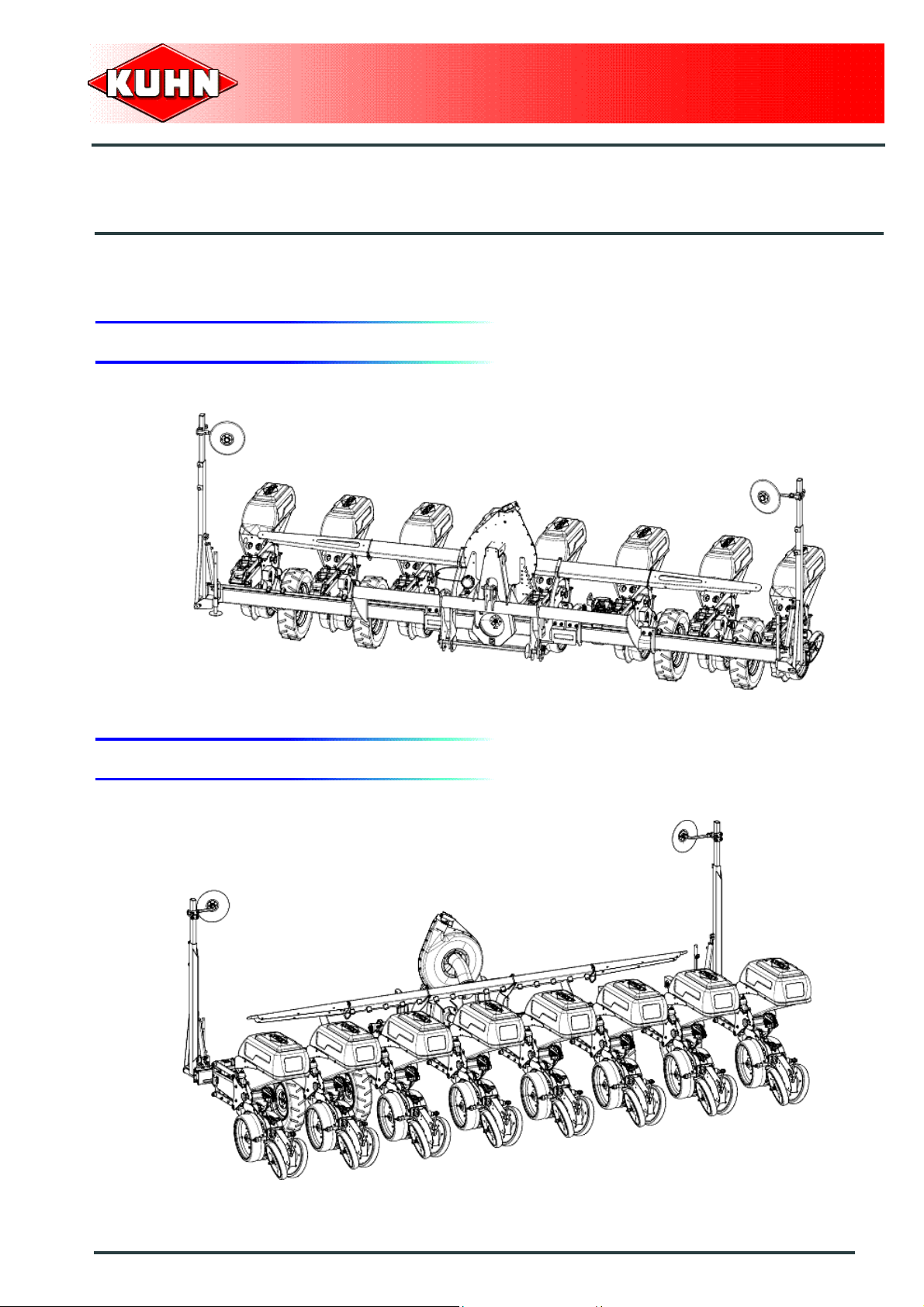
$IDENTIFICATION OF THE MACHINE
1. Front view (Basic machine)
Precision Seed Drills
MAXIMA 2
2. Rear view (Basic machine)
Identification of the machine
5
Page 8
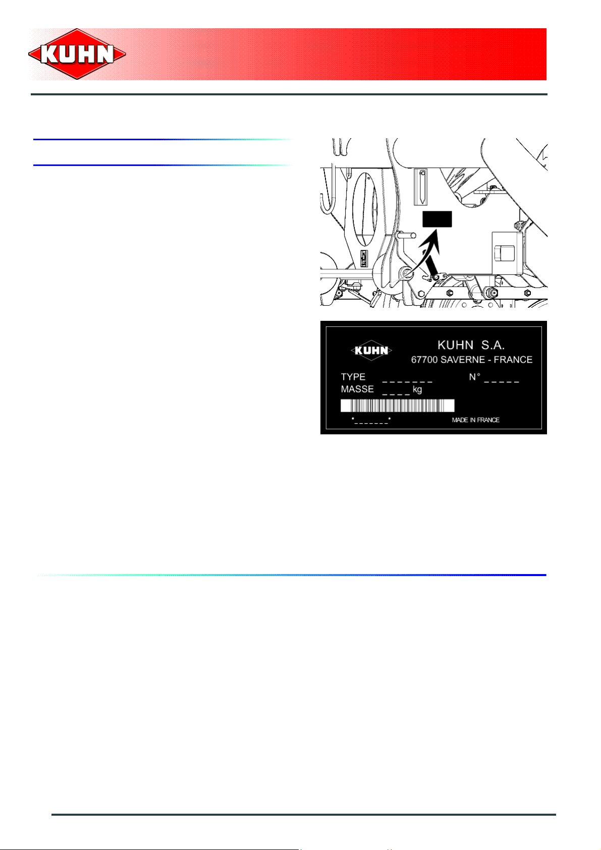
3. Model identification plate
Please write below the type and serial number of the
machine. This information is to be indicated to the dealer
for all spare parts orders.
Precision Seed Drills
MAXIMA 2
Type: MAXIMA 2
Serial no.:
6
Identification of the machine
Page 9

4. Optional equipment
Tick box corresponding to the equ ipment fitted on your
machine:
Sowing component
Kit no. 1676801: Clod clearer with disk coulter for * 1 gauge wheels.
Kit no. 1676802: Clod clearer with disk coulter for * 1 gauge wheels.
Kit no. 1676803: Spring assisted clod clearer.
Kit no. 1676783: Star shaped trash remover.
Kit no. 1676775: Opener disc solo.
Precision Seed Drills
MAXIMA 2
Kit no. 1676780: Furrow opening disk with star-shaped trash remover.
Kit no. 1676761: Covering scraper.
Kit no. 1676762: Composite intermediate axial press wheel.
Kit no. 1676766: Stainless steel intermediate axial press wheel.
Kit no. 1676790: Furrow closing disks.
Kit no. 1677235: Standard Rubber V roller 1’’.
Kit no. 1677234: Standard Rubber V roller 2’’.
Kit no. 1677237: Standard smooth steel V roller.
Kit no. 1677236: Standard notched steel V roller.
Kit no. 1677241: HD Rubber V roller 1’’.
Kit no. 1677240: HD Rubber V roller 2’’.
Kit no. 1677239: HD smooth steel V roller.
Kit no. 1677238: HD notched steel V roller.
Kit no. 1676757: 370 x 165 OTIFLEX roller and covering scrapers.
Kit no. 1676859: 370 x 165 OTIFLEX roller and furrow closing disks.
Kit no. 1676758: 500 x 175 OTIFLEX roller and covering scrapers.
Kit no. 1676863: 500 x 175 OTIFLEX roller and furrow closing disks.
Identification of the machine
7
Page 10

Drive
Kit no. 1676503: Left and right rear drive wheels 5 x 15.
Kit no. 1676502: Left and right rear drive wheels 6.5 x 15.
Kit no. 1676501: Left and right rear drive wheels 26 x 12.
Microgranulator
For the following models:
M2B12MB600C001
M2B12MB600C002
M2M12MB900C002
First equipment microgranulator
Precision Seed Drills
MAXIMA 2
Kit no. 1677175: Insecticide microgranulator 12 rows, 2x80 L (2x21 US gal) hoppers with front blower and fitting
on air duct.
Kit no. 1677176: Slug pellet microgranulator 12 rows, 2x80 L (2x21 US gal) hoppers with front blower and fitting
on air duct.
Kit no. 1677177: Herbicide microgranulator 12 rows, 2x150 (2x40 US gal) hoppe rs with front bl ower and fitting on
air duct.
Second equipment microgranulator
Kit no. 1677178: Insecticide microgranulator 12 rows, with 2x80 L (2x21 US gal) hoppers and fitting on air duct.
Kit no. 1677179: Slug pellet microgranulator 12 rows, with 2x80 L (2x21 US gal) hoppers and fitting on air duct.
Kit no. 1677180: Herbicide microgranulator 12 rows, with 2x150 (2x40 US gal) hoppers and fitting on air duct.
For the following models:
M2B12MB600CG01
M2B12MB600CG02
M2M12MB900CG02
First equipment microgranulator
Kit no. 1677181: Insecticide microgranulator 12 rows with 2x80 L (2x21 US gal) hoppers and upper fitting.
Kit no. 1677182: Slug pellet microgranulator 12 rows with 2x80 L (2x21 US gal) hoppers and upper fitting.
Kit no. 1677183: Herbicide microgranulator 12 rows with 2x150 L (2x40 US gal) hoppers and upper fitting.
8
Identification of the machine
Page 11

Precision Seed Drills
MAXIMA 2
For the following models:
M2B18MB900C001
M2B18MB900C002
First equipment microgranulator
Kit no. 1677184: Insecticide microgranulator 18 rows, 2x100 L (2x26 US gal) hoppers with front blower an d fitting
on air duct.
Kit no. 1677185: Slug pellet microgranulator 18 rows, 2x100 L (2x26 US gal) hoppers with front blowe r and fitting
on air duct.
Kit no. 1677186: Herbicide microgranulator 18 rows, 2x190 (2x50 US gal) hoppers with front blower and fitting o n
air duct.
Second equipment microgranulator
Kit no. 1677187: Insecticide microgranulator 18 rows, with 2x100 L (2x26 US gal) hoppers and fitting on air duct.
Kit no. 1677188: Slug pellet microgranulator 18 rows, with 2x100 L (2x26 US gal) hoppers and fitting on air duct.
Kit no. 1677189: Herbicide microgranulator 18 rows, with 2x190 (2x50 US gal) hoppers and fitting on air duct.
For the following models:
M2M08MB600C002
First equipment microgranulator
Kit no. 1677163: Insecticide microgranulator 8 rows, 100 L (2x26 US gal) hopper with front blower and fitting on
air duct.
Kit no. 1677164: Slug pellet microgranulator 8 rows, 100 L (26 US gal) hopper with front blower and fitting on air
duct.
Kit no. 1677165: Herbicide microgranulator 8 rows, 190 (50 US gal) hopper with front blower and fitting on air duct.
Second equipment microgranulator
Kit no. 1677139: Insecticide microgranulator 8 rows with 100 L (26 US gal) hopper and fitting on air duct.
Kit no. 1677140: Slug pellet microgranulator 8 rows with 100 L (26 US gal) hopper and fitting on air duct.
Kit no. 1677292: Herbicide microgranulator 8 rows with 190 L (50 US gal) hopper and fitting on air duct.
For the following models:
M2M08MB600CG02
First equipment microgranulator
Kit no. 1677145: Insecticide microgranulator 8 rows with 100 L (21 US gal) hopper and fitting in high position.
Kit no. 1677146: Anti-slug pellet microgranulator 8 rows with 100 L (21 US gal) hopper a nd fitting in h igh position.
Kit no. 1677147: Herbicide microgranulator 8 rows with 190 L (40 US gal) hopper and fitting in high position.
Identification of the machine
9
Page 12

Precision Seed Drills
MAXIMA 2
Second equipment microgranulator
Kit no. 1677145: Insecticide microgranulator 8 rows with 100 L (21 US gal) hopper and fitting in high position.
Kit no. 1677146: Anti-slug pellet microgranulator 8 rows with 100 L (21 US gal) hopper and fitting in high position.
Kit no. 1677147: Herbicide microgranulator 8 rows with 190 L (40 US gal) hopper and fitting in high position.
For the following models:
M2S11MB440C002
M2S11MB440CF02
M2S11MB500C003
First equipment microgranulator
Kit no. 1677148: Insecticide microgranulator 11 rows, 2x80 L (2x21 US gal) hoppers with front blower and fitting
on air duct.
Kit no. 1677149: Slug pellet microgranulator 11 rows, 2x80 L (2x21 US gal) hoppers with front blower and fitting
on air duct.
Kit no. 1677150: Herbicide microgranulator 11 rows, 2x1 50 (2x40 US gal) hoppe rs with front bl ower and fitting on
air duct.
Second equipment microgranulator
Kit no. 1677151: Insecticide microgranulator 11 rows, with 2x80 L (2x21 US gal) hoppers and fitting on air duct.
Kit no. 1677152: Slug pellet microgranulator 11 rows, with 2x80 L (2x21 US gal) hoppers and fitting on air duct.
Kit no. 1677153: Herbicide microgranulator 11 rows, with 2x150 (2x40 US gal) hoppers and fitting on air duct.
For the following models:
M2S11MB500CG03
First equipment microgranulator
Kit no. 1677154: Insecticide microgranulator 11 rows with 2x80 L (2x21 US gal) hoppers and upper fitting.
Kit no. 1677155: Slug pellet microgranulator 11 rows with 2x80 L (2x21 US gal) hoppers and upper fitting.
Kit no. 1677156: Herbicide microgranulator 11 rows with 2x150 L (2x40 US gal) hoppers and upper fitting.
For the following models:
M2T09MB500C002
M2T09MB600C002
First equipment microgranulator
10
Identification of the machine
Page 13

Precision Seed Drills
MAXIMA 2
Kit no. 1677157: Insecticide microgranulator 9 rows, 100 L (2x26 US gal) hopper with front blower and fitting on
air duct.
Kit no. 1677158: Slug pellet microgranulator 9 rows, 100 L (26 US gal) hopper with front blower and fitting on air
duct.
Kit no. 1677159: Herbicide microgranulator 9 rows, 190 (50 US gal) hopper with front blower and fitting on air duct.
Second equipment microgranulator
Kit no. 1677160: Insecticide microgranulator 9 rows with 100 L (26 US gal) hopper and fitting on air duct.
Kit no. 1677161: Slug pellet microgranulator 9 rows with 100 L (26 US gal) hopper and fitting on air duct.
Kit no. 1677162: Herbicide microgranulator 9 rows with 190 L (50 US gal) hopper and fitting on air duct.
Fertilizer unit
For the following models:
M2B12MB600C001
M2B12MB600C002
M2M12MB900C002
Kit no. 1677327: Fertilizer 12 rows with front mounted hopper and applicators with standard Suffolk coulters.
Kit no. 1677328:Fertilizer 12 rows with front mounted hopper and applicators with non-stop Suffolk coulters.
Kit no. 1677329: Fertilizer 12 rows with front mounted hopper and applicators with non-stop disk coulters.
For the following models:
M2B12MB600CG01
M2B12MB600CG02
Kit no. 1677049: Fertilizer 12 rows with 1350 L (356 US gal) hopper and applicators with standard Suffolk coulters.
Kit no. 1677050: Fertilizer 12 rows with 1350 L (356 US gal) hopper and applicators with non-stop Suffolk coulters.
Kit no. 1677051: Fertilizer 12 rows with 1350 L (356 US gal) hopper and applicators with non-top disk coulters.
For the following models:
M2M08MB600C002
Kit no. 1677324: Fertilizer 8 rows with front mounted hopper and applicators with standard Suffolk coulters.
Kit no. 1677325: Fertilizer 8 rows with front mounted hopper and applicators with non-stop Suffolk coulters.
Kit no. 1677326: Fertilizer 8 rows with front mounted hopper and applicators with non-stop disk coulters.
Identification of the machine
11
Page 14

Precision Seed Drills
MAXIMA 2
For the following models:
M2M08MB600CG02
Kit no. 1677046: Fertilizer 8 rows with 1350 L (356 US gal) hopper and applicators with standard Suffolk coulters.
Kit no. 1677047: Fertilizer 8 rows with 1350 L (356 US gal) hopper and applicators with non-stop Suffolk coulters.
Kit no. 1677048: Fertilizer 8 rows with 1350 L (356 US gal) hopper and applicators with non-top disk coulters.
For the following models:
M2M12MB900CG02
Kit no. 1677055: Fertilizer 12 rows with 1350 L (356 US gal) hopper and applicators with standard Suffolk coulters.
Kit no. 1677056: Fertilizer 12 rows with 1350 L (356 US gal) hopper and applicators with non-stop Suffolk coulters.
Kit no. 1677057: Fertilizer 12 rows with 1350 L (356 US gal) hopper and applicators with non-top disk coulters.
For the following models:
M2S11MB440CF02
Kit no. 1677022: Fertilizer 6 rows with 2X280 L (2X74 US gal) hoppers and applicators with standard Suffolk coulter.
Kit no. 1677023: Fertilizer 6 rows with 2X280 L (2X74 US gal) hoppers and applicators with non-stop Suffolk coulter.
Kit no. 1677024: Fertilizer 6 rows with 2X280 L (2X74 US gal) hoppers and applicators non-stop disk coulters.
For the following models:
M2S11MB500CG03
Kit no. 1677043: Fertilizer 6 rows with 1350 L (356 US gal) hopper and applicators with standard Suffolk coulters.
Kit no. 1677044: Fertilizer 6 rows with 1350 L (356 US gal) hopper and applicators with non-stop Suffolk coulters.
Kit no. 1677045: Fertilizer 6 rows with 1350 L (356 US gal) hopper and applicators with non-top disk coulters.
Kit no. 1677228: Low flow kit for the fertilizer unit.
Kit no. 1677225: Loading screw for fertilizer equiped with 2x280 L (2x74 US gal) hoppers.
Kit no. 1677226: Loading screw for fertilizer unit fitted with a 1350 L (356 US gal) hopper.
Distribution disks
SP = Disk without agitator blades.
AP = Disk with agitator blades.
Kit no. N1503620: Distribution disk 12 holes of diameter 1.5 mm (0.06’’) AP.
Kit no. N04343B0: Distribution disk 12 holes of diameter 2.5 mm (0.1’’) AP.
12
Identification of the machine
Page 15

Precision Seed Drills
Kit no. N1502090: Distribution disk 12 holes of diameter 3.5 mm (0.14’’) AP.
Kit no. N04286B0: Distribution disk 18 holes of diameter 1.5 mm (0.06’’) SP.
Kit no. N00846B0: Distribution disk 18 holes of diameter 2.5 mm (0.1’’) AP.
Kit no. N04318B0: Distribution disk 18 holes of diameter 3 mm (0.12’’) AP.
Kit no. N00847B0: Distribution disk 18 holes of diameter 3.5 mm (0.14’’) AP.
Kit no. N00856B0: Distribution disk 22 holes of diameter 2.1 mm (0.08’’) SP.
Kit no. N1503810: Distribution disk 22 holes of diameter 2.1 mm (0.08’’) AP.
Kit no. N04341B0: Distribution disk 22 holes of diameter 2.5 mm (0.1’’) AP.
Kit no. N03840B0: Distribution disk 22 holes of diameter 3.5 mm (0.14’’) AP.
Kit no. N00851B0: Distribution disk 22 holes of diameter 4.5 mm (0.18’’) AP.
MAXIMA 2
Kit no. N02511B0: Distribution disk 22 holes of diameter 5 mm (0.2’’) AP.
Kit no. N00852B0: Distribution disk 22 holes of diameter 5.5 mm (0.22’’) AP.
Kit no. N1503140: Distribution disk 27 holes of diameter 2.5 mm (0.1’’) AP.
Kit no. N1500670: Distribution disk 27 holes of diameter 3 mm (0.12’’) SP.
Kit no. N03823B0: Distribution disk 27 holes of diameter 3.5 mm (0.14’’) AP.
Kit no. N00843B0: Distribution disk 27 holes of diameter 4.5 mm (0.18’’) AP.
Kit no. N00905B0: Distribution disk 27 holes of diameter 5 mm (0.2’’) AP.
Kit no. N00844B0: Distribution disk 27 holes of diameter 5.5 mm (0.22’’) AP.
Kit no. N1500340: Distribution disk 30 holes of diameter 7 mm (0.28’’) AP.
Kit no. N00845B0: Distribution disk 31 holes of diameter 2.1 mm (0.08’’) SP.
Kit no. N00855B0: Distribution disk 33 holes of diameter 3.5 mm (0.14’’) AP.
Kit no. N04107B0: Distribution disk 33 holes of diameter 4.5 mm (0.18’’) AP.
Kit no. N04282B0: Distribution disk 33 holes of diameter 5.5 mm (0.22’’) AP.
Kit no. N1503380: Distribution disk 35 holes of diameter 3.5 mm (0.14’’) AP.
Kit no. N1503390: Distribution disk 35 holes of diameter 4.5 mm (0.18’’) AP.
Kit no. N1503400: Distribution disk 35 holes of diameter 5 mm (0.2’’) AP.
Kit no. N1503410: Distribution disk 35 holes of diameter 5.5 mm (0.22’’) AP.
Kit no. K3601440: Distribution disk 48 holes of diameter 1.25 mm (0.05’’) SP.
Kit no. N02951B0: Distribution disk 48 holes of diameter 2.5 mm (0.1’’) AP.
Identification of the machine
13
Page 16

Precision Seed Drills
Kit no. N00848B0: Distribution disk 48 holes of diameter 3.5 mm (0.14’’) AP.
Kit no. N04305B0: Distribution disk 48 holes of diameter 4.5 mm (0.18’’) AP.
Kit no. N1503130: Distribution disk 48 holes of diameter 5.5 mm (0.22’’) AP.
Kit no. N1500061: Distribution disk 54 holes of diameter 3 mm (0.12’’) SP.
Kit no. N1500681: Distribution disk 54 holes of diameter 4.5 mm (0.18’’) AP.
Kit no. N1500691: Distribution disk 54 holes of diameter 5.5 mm (0.22’’) AP.
Kit no. N1500431: Distribution disk 70 holes of diameter 1.25 mm (0.05’’) SP.
Kit no. N02851B0: Distribution disk 70 holes of diameter 2.5 mm (0.1’’) AP.
Kit no. N04342B0: Distribution disk 70 holes of diameter 3.5 mm (0.14’’) AP.
Kit no. N00850B0: Distribution disk 70 holes of diameter 4.5 mm (0.18’’) AP.
MAXIMA 2
Kit no. N1502170: Distribution disk 80 holes of diameter 2.5 mm (0.1’’) AP.
Kit no. N1501591: Distribution disk 80 holes of diameter 3.5 mm (0.14’’) AP.
Kit no. N1501051: Distribution disk 100 holes of diameter 0.8 mm (0.03’’) SP.
Kit no. N00849B0: Distribution disk 100 holes of diameter 1.25 mm (0.05’’) SP.
Kit no. N1500701: Distribution disk 100 holes of diameter 1.75 mm (0.07’’) AP.
Kit no. N04293B0: Distribution disk 100 holes of diameter 3.5 mm (0.14’’) AP.
Blower
Kit no. 1677287: 470 min
Kit no. 1676731: 870 min
Kit no. 1676738: 1000 min
-1
pulley and belt unit
-1
pulley and belt unit
-1
pulley and belt unit
Kit no. 1676730: Rear PTO output stub.
Kit no. 1677223: Vacuometer.
Control units
Kit no. 1676822: HECTOR 3000 electronic unit.
Passage control box kit KMS208:
Kit no. 1676648: For machine with 8 rows.
Sowing control box kit KMS412:
Kit no. 1676408B: For machine with 8 rows.
14
Identification of the machine
Page 17

Kit no. 1676409B: For machine with 9 rows.
Kit no. 1676411B: For machine with 11 rows.
Kit no. 1676412B: For machine with 12 rows: Sowing Beet.
Kit no. 1676413B: For machine with 12 rows: Sowing maize.
Kit no. 1676418B: For machine with 18 rows.
Electronic disengagement kit:
Kit no. 1677299: For machine with 8 rows
Kit no. 1677300: For machine with 9 rows
Kit no. 1677301: For machine with 11 rows
Kit no. 1677302: For machine with 12 rows
Precision Seed Drills
MAXIMA 2
Sundry
Kit no. 1676520: 65 x 400 depth control wheels.
Kit no. 1677293: 45 mm (1.8’’) spacer and 5 mm (0.2 ’’) levelling pad.
Kit no. 1676792: 82 mm (3.2’’) spacer and 5 mm (0.2 ’’) levelling pad.
Kit no. 1676825: Wheel footbridges.
Kit no. 1626614: Track eradicators.
Kit no. 1676815: Marker working depth limitors.
Kit no. 1676820: Mechanical hectare counter.
Identification of the machine
15
Page 18

$SAFETY
1. Description of symbols used in this document
This symbol indicates a potentially hazardous situation
that if not avoided, could result in serious bodily injury.
Precision Seed Drills
MAXIMA 2
This symbol is used to identify special instructions or
procedures which, if not followed strictly, could result in
machinery damage.
This symbol is used to communicate technical
information of particular interest.
16
Safety
Page 19
Precision Seed Drills
MAXIMA 2
2. Safety instructions
Introduction
The machine must only be operated, maintained and repaired by competent persons who are familiar with
machines' specifications and operation and aware of safety regulations for preventing accidents.
The operator must imperatively respect safety instructions in this manual and in the warnings posted on the
machine. The operator is also obliged to respect cu rrent legislation concerning accident pr evention, work safety
and public traffic circulation.
Designated use of the machine al so means following operation, maintenance and repair recommendations
given by the manufacturer, and using only genuin e spa re parts, e quip ment and accesso rie s, as re commen de d
by the manufacturer.
The manufacturer is not held liable for any damage resulting from machine applications other than those
specified by the manufacturer. Any use other than the designated operation is at the risk and responsibility of
the operator.
The manufacturer is not held liable for any damage or accident resulting from machine modifications carried out
by the operator himself or by a third party without previous written agreement from the manufacturer.
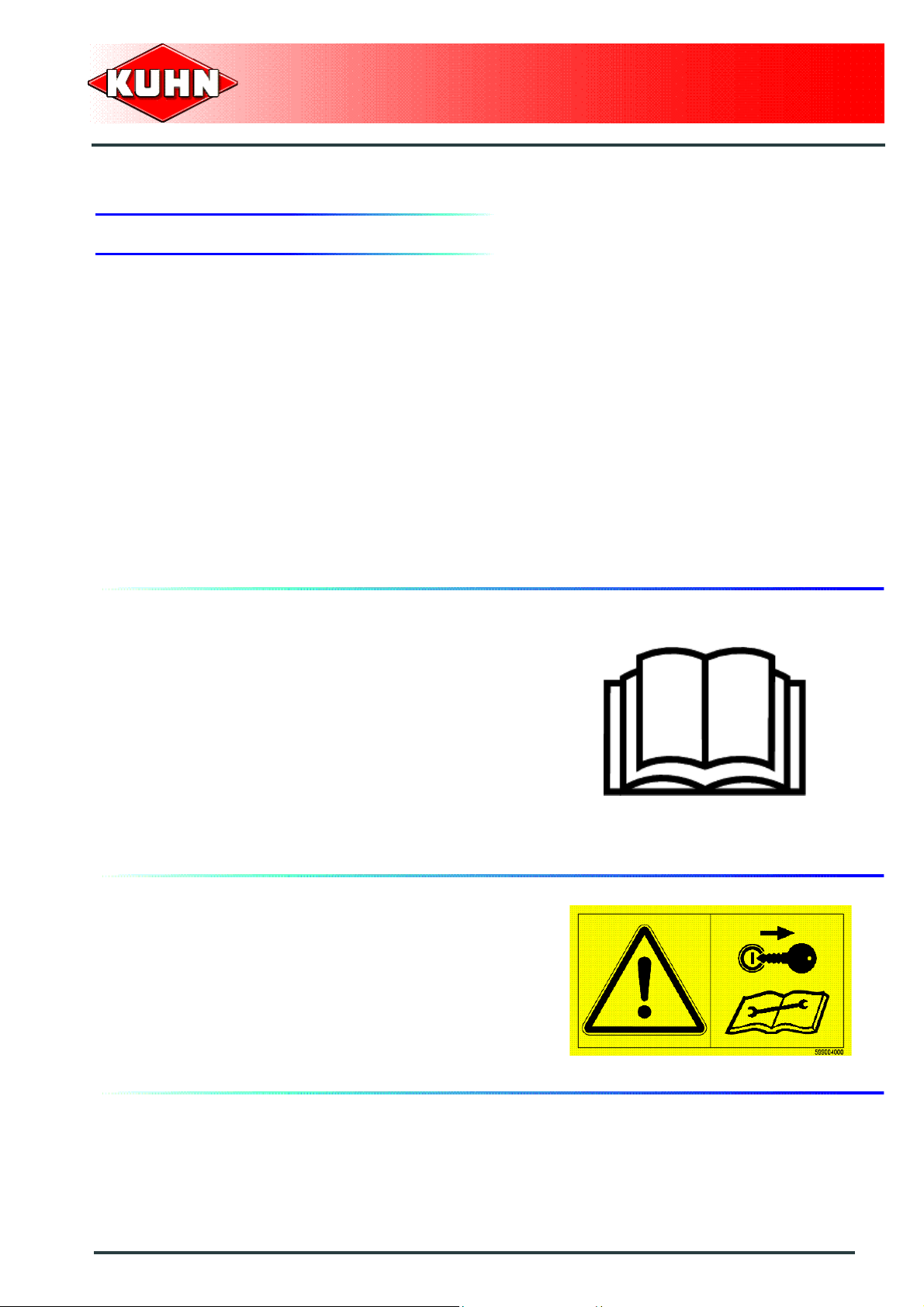
Read and follow the safety instructions
Before using the machine, carefully read all the safety
instructions in this manual and the warnings placed on
the machine.
Before starting work, the operator must be familiar with
all machine controls, handling devices and their
functions. It is too late to learn once work has been
started!
Never let anyone operate the machine who is not trained
to do so.
Should you have any difficulties in understanding certain
parts in this manual, please contact your KUHN dealer.
Precautions to be taken before carrying out
any operations on the machine
Before leaving the tractor or before adjusting,
maintaining or repairing the machine, disengage the
PTO drive, turn off the engine , remove ignition k ey and
wait until all moving parts have come to a complete stop
and apply park brake.
Safety
17
Page 20
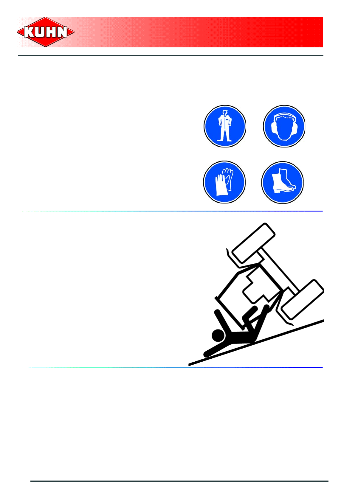
Precautions to take before using the
machine
Do not wear loose clothing which could become caught
up in moving parts.
Wear the appropriate protective clothing for the work in
hand (gloves, shoes, goggles, helmet, ear-protectors,
etc.).
Ensure that all operating controls (ropes, cables, rods,
etc) are placed so as they cannot be operated
unintentionally and cause damage or injury.
Before operating the machine, check tightness of nuts
and bolts, particularly on fixing elements (tines, forks,
blades, knives, etc). Retighten if necessary.
Before operating the machine, ensure that all the safety
guards are firmly in place and in good condition.
Immediately replace any worn or damaged guard.
Precision Seed Drills
MAXIMA 2
Precautions when driving
Tractor handling, stability, performance and braking
efficiency are all affected by weight distribution, trailed or
mounted implements, additional ballast and driving
conditions. It is therefore of the great importance that the
operator exercises caution in every given situation.
Groundspeed must be adapted to ground conditions as
well as to roads and paths. Always avoid abrupt changes
of direction.
Be particularly cautious when turning corners, paying
attention to machine overhang, length, height and
weight.
Never use a narrow track tractor on very uneven or
steeply sloping ground.
Never leave the tractor seat while the machine is
operating.
Carrying people or animals on the machine when
working or in transport is strictly forbidden.
18
Safety
Page 21
Precautions when driving on public roads
Dimensions
Depending on the dimensions of the machine, contact
the relevant authorities to ensure that it can be legally
transported on public roads.
If the machine is over the maximum legal size, follow th e
local regulations for special transportation of oversize
equipment.
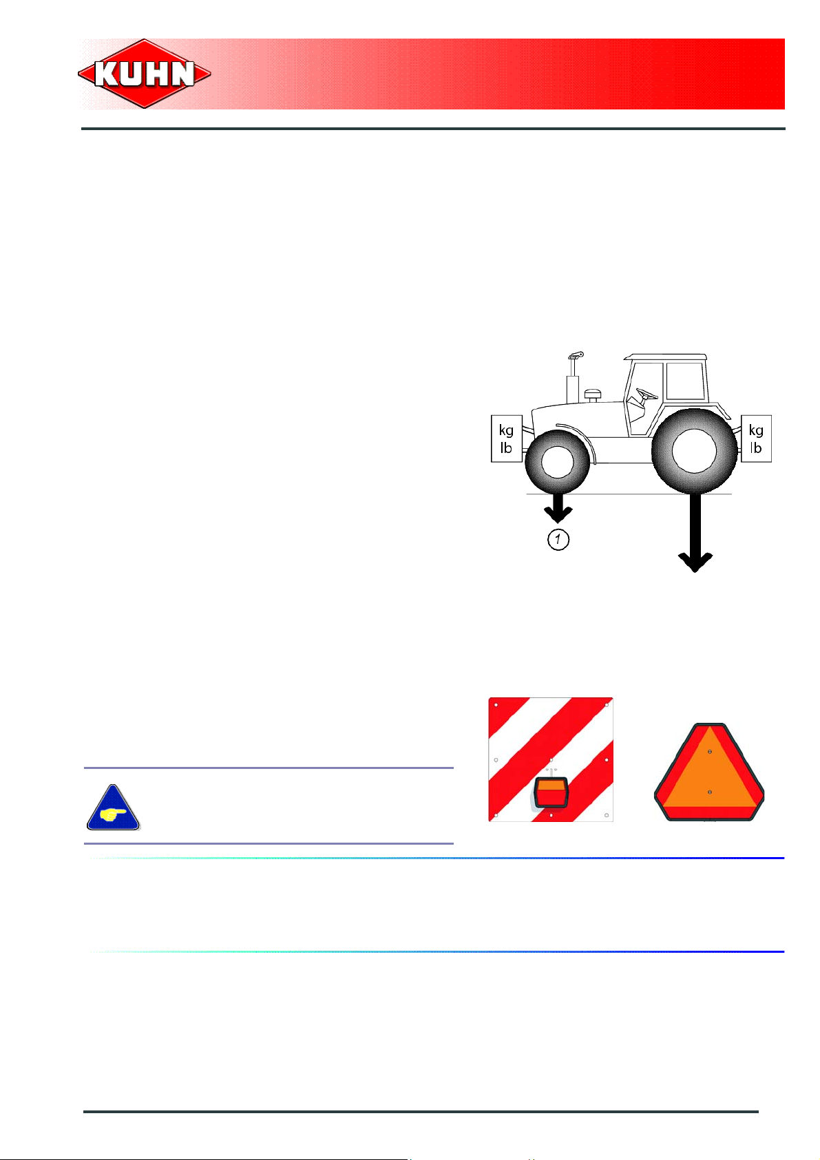
Gross weight and weight per axle
Check that the tractor's authorized gross weight as well
as its lift capacity and maximum weight per axle are not
exceeded.
The front axle load (1) must never, under any
circumstances, be less than 20% of the tractor's unladen
weight. If necessary, add ballast weights to the front or
to the rear to preserve the steering and braking
efficiency.
Precision Seed Drills
MAXIMA 2
Transport position
Before transporting the machine on public roads, place
the machine into its transport position, according to the
instructions in this manual.
Lightings and signallings
Before transporting the machine on public roads, e nsure
that all legally required lightings and signallings are in
place.
Ensure that lightings and signallings are clean and in
good working order. Replace any missing or broken
equipment.
Always obey current regulations for driving
on roads.
Maximum speed
Always keep to the legal speed limit for driving a tractormachine assembly on public roads.
Safety
19
Page 22
Precautions when coupling
Before attaching the machine, make sure that it cannot
accidentally start moving (chock the wheels) and that the
parking stand is in the right position.
The machine must only be attached to the hitch points
provided for this purpose.
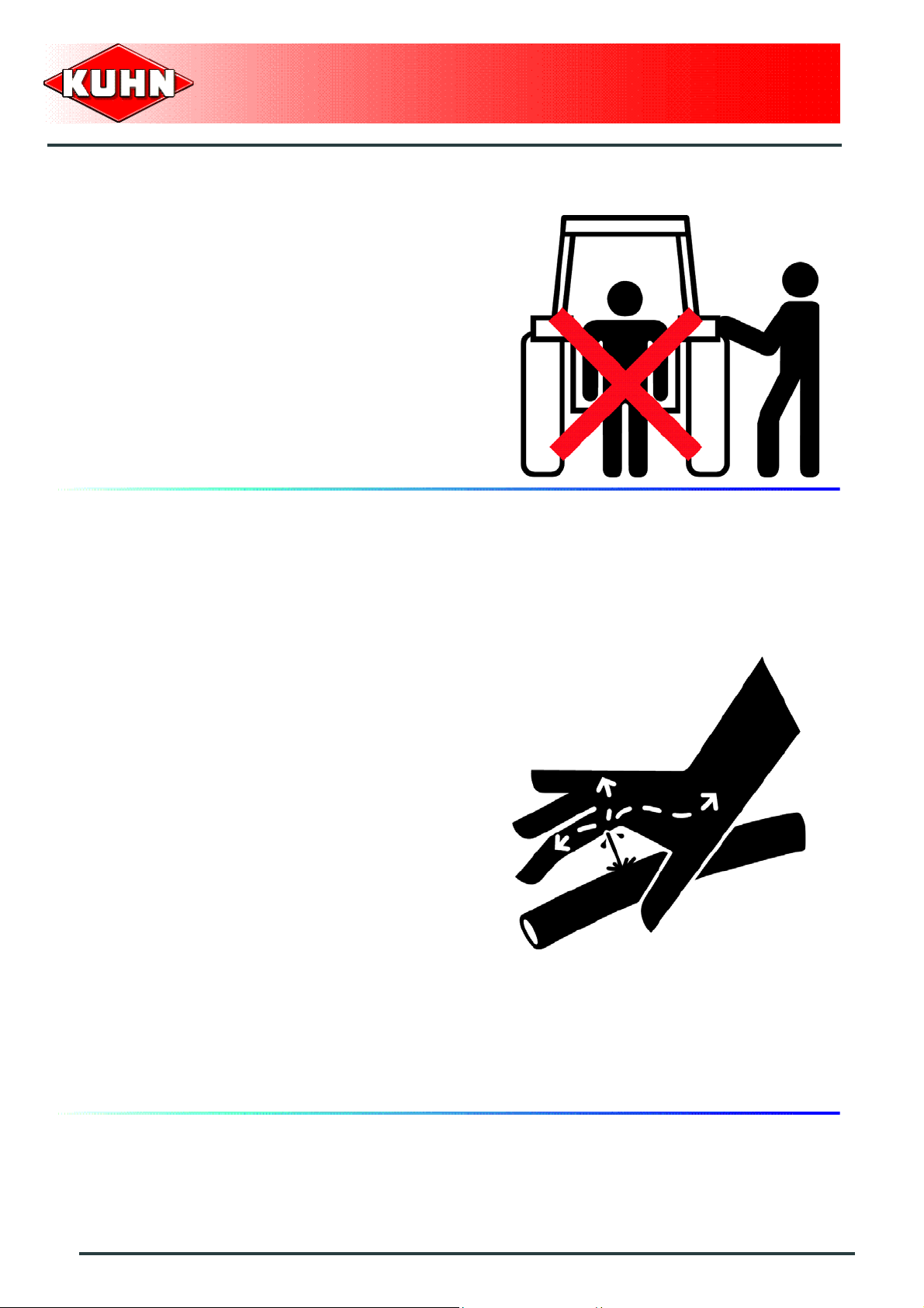
Never stand between the tractor and the machine when
operating the three point linkage.
Do not stand between the tractor and the machine
without ensuring that the parking brake is applied.
Hydraulic circuit
Precision Seed Drills
MAXIMA 2
Beware : The hydraulic circuit is under pressure.
Maximum pressure at work: 200 bar (2857 psi).
Before connecting hoses to the tractor hydraulics,
ensure that tractor and machine circuits are not under
pressure. Before disconnecting a hose, depressurize the
hydraulic circuit.
To avoid making incorrect connections, mark hydraulic
couplers and corresponding hoses with colors.
WARNING! Functions could be reversed (for example:
lift/lower) and cause accidents.
Regularly check the hydraulic hoses. In cas e of normal
wear, replace the hydraulic hoses every 5 years.
Damaged or worn hoses must immediately be replaced.
When replacing the hydraulic hoses, make sure to use
hoses with the specifications and quality recommended
by the manufacturer of the machine.
To locate a leak, use appropriate means.
Protect body and hands from liquid under pressure.
Any liquid under pressure (particularly oil from
hydraulics) can penetrate the skin and cause severe
injury. If injured, see a doctor immediately, there could
be danger of infection.
Before any adjustments, maintenance or repairs are
carried out, lower the machine on the ground,
depressurize the hydraulics, turn off the engine, remove
ignition key and wait until all moving parts have come to
a complete stop.
20
Safety
Page 23

PTO shaft
Use only PTO shafts supplied with the machine or
recommended by the manufacturer.
The protective shield of the tractor PTO stub, the PTO
shaft guards and the protective covering of the machine
input shaft must always be in place and in good
condition.
Make sure that the PTO shaft guards are secured with
the safety chains provided.
Any worn or damaged guards must be replaced
immediately. A worn guard or an unprotected PTO shaft
can cause a serious or even a lethal accident.
Do not wear loose clothing that could be caught in the
rotating PTO shaft.
Before attaching or removing a PTO shaft, or before
doing any work on the machine, disengage the PTO
drive, turn off the engine, remove ignition key and wait
for all moving parts have come to a complete stop.
If the primary PTO shaft is equipped with a slip clutch or
a free wheel, these must be fitted on the machine side.
Ensure that the PTO shaft is always correctly fitted and
locked into place.
Before connecting the PTO shaft, ensure that the PTO
speed (rotational frequency) and directions of rotation
are in line with manufacturer's recommendations.
Before engaging the PTO drive, make sure all people
and animals are clear from the machine. Never engage
the PTO drive when the tractor engine is stopped.
When uncoupling the machine, rest the PTO shaft on the
support specially provided, and replace protective co ver
on the PTO stub of the tractor.
Read and follow the instructions in the operator's m anual
provided with the PTO shaft.
Precision Seed Drills
MAXIMA 2
Safety
21
Page 24

Precautions during manoeuvres
When moving the machine from the transp ort position to
the working position and vice versa, make sure that
nobody is within the machine pivoting area.
Remote controlled components
Danger of crushing and shearing can exist when
components are operated by hydraulic or pneumatic
controls. Keep away from these danger zones.
Safety decals
Safety warning decals to respect, are placed in pictorial
form on various parts of the machine. They are there to
warn you of potential dangers and to tell you how to
avoid accidents.
Always keep the safety decals clean and readable, and
replace them when they are worn, damaged, missing or
illegible.
Precision Seed Drills
MAXIMA 2
Waste disposal
Respect the environment! Never spill pollutants (oil,
grease, filters etc.) on the ground neither pour them
down the drain or discard them in any other place where
they could pollute the environment. Never throw away or
burn a tire. Always take waste to specialized recycling or
waste disposal centers.
22
Safety
Page 25

Precautions for maintenance and repair
work
Before leaving the tractor or before adjusting,
maintaining or repairing the machine, disengage the
PTO drive, turn off the engine , remove ignition k ey and
wait until all moving parts have come to a complete stop
and apply park brake.
Rest the machine on the ground, release the pressure
from the hydraulic circuit and leave the machine to cool
down.
Make sure that the parts of the machine that need to be
lifted for maintenance or repair work are firmly propped
up.
Before any work is done on th e electric circ uit or befo re
any electric welding is carried out on the attached
machine, disconnect the machine from the tractor
electrical circuit. Also disconnect alternator and battery
terminals.
Repairs on elements under pressure or tension (springs,
pressure accumulators, etc.) must only be carried out by
competent persons with regulation equipment.
Wear the appropriate protective clothing for the work in
hand (gloves, shoes, goggles, helmet, ear-protectors,
etc.).
Do not solder, weld or use a blow torch near fluids under
pressure or inflammable products.
For your own safety and for correct machine operation,
only use original manufacturer parts.
It is strongly recommended to have your machine
checked by your Kuhn dealer after each season,
especially tools and their attaching hardware.
Precision Seed Drills
MAXIMA 2
Projection of stones and foreign objects
For driver safety, always use a tractor equipped with a
cab. Never start the machine when there are people
nearby. Even when the machine is used in accordance
with its purpose, objects may be projected. Stones and
other foreign objects projected by the moving parts can
travel a considerable distance. Keep all persons and
animals away from the danger zone.
Safety
23
Page 26

Precautions for machine use
Before use, check the condition of the fasteners in
accordance with the instructions contained in this
manual.
Keep all persons and animals away from the danger
zone. Check that nobody is within the side marker
operating area on headlands.
Stay a safe distance from the machine when the cuttin g
tools are in movement.
Never work in reverse.
Stay away from the machine until all moving parts have
come to a complete standstill.
Check the entire machine for any damage before
resuming work.
Never engage the tractor PTO drive when the machine
is in transport position.
If the machine hits an obstacle, disengage the PTO
drive, stop the tractor engine, remove the ignition key
and wait for all moving parts to come to a complete
standstill. Check the entire machine for any damage
before resuming work.
Precision Seed Drills
MAXIMA 2
Precautions to take with crop protection
products
Keep crop protection products away from children.
Do not clean outlets, spreaders, tubes or other small
parts by blowing with the mouth. When using crop
protection products, never smoke or eat.
All precautions must be taken to prevent hopper from
overflowing and products from flowing outside the
treatment area.
Booms and tanks are to be drained in all cases over the
areas under cultivation in accordance with regulatory
provisions.
Keep machine control and handling devices clean and
make sure to wash your hands prior to using these
devices.
Rinse and pierce packagings to prevent them from being
reused.
Find out about and comply with the instructions on the
use of crop protection products with regards to their
possible harmfulness for insects and wildlife, especially
for pollinating insects.
24
Safety
Page 27
Consulting and respecting the rules given in the
operating instructions, the safety files and in the advice
documents is the basis of behaving responsibly.
Store crop protection products in a place with a leakproof
floor enabling to recover product leaks.
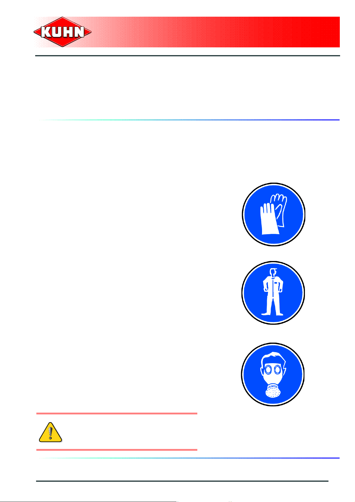
Body protection
Wear waterproof clothing whenever there is a risk of
splashing from or contact with crop protection products,
even in diluted form. Wear specific protective clothing
(suit, gloves, boots, glasses, mask) when handling
phytosanitary products).
Wear gloves that are resistant to the various
components contained in the products (ultranitrile
gloves). Neoprene gloves are required in the presence
of ketone in the formulations.
Strictly avoid certain materials such as late x or PVC. A
watertightness indicator is insufficient.
Replace gloves as soon as they present signs of wear.
Store the gloves in a place well away from the products.
Precision Seed Drills
MAXIMA 2
Use special protection suits resistant to the products.
Wear a respiratory protection when preparing the spray
mixture or spraying certain products.
Check that the respiratory protections are fitted with
filters.
Change cartridges every 40h during intensive use
periods.
Replace respiratory protection at least once per year.
Anti-dust masks do not protect sufficiently
against phytosanitary products.
Safety
25
Page 28

Toxic substances
It is recommended to have a first-aid kit within reach.
Avoid all skin, eyes and mouth contact with products
such as fuels, oils, solvents, antifreeze and cleaning
products. Most of them contain harmfull substances.
In case of an incident, seek medical advice.
Follow to the letter all instructions given on the safety
decals of toxic substance containers.
Compatibility of phytosanitary products
and microgranulators
There are no known contraindication of incompatibility
between solid phytosanitary products and the material
used in the microgranulator assembly.
Precision Seed Drills
MAXIMA 2
26
Safety
Page 29
3. Location and description of safety decals on the machine
Location of safety decals
Precision Seed Drills
MAXIMA 2
Safety
27
Page 30

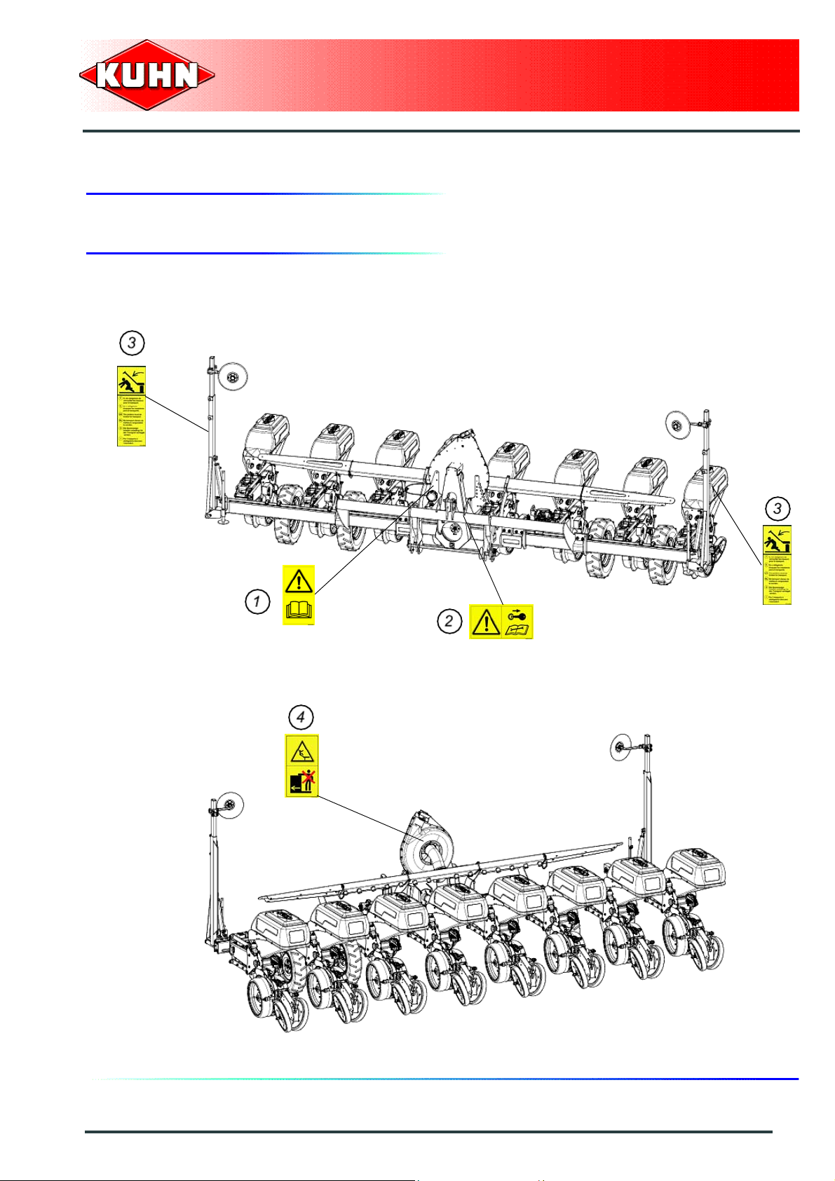
Description of safety decals
Operating instructions (1)
The operators' manual contains all the information
necessary for using the machine safely. It is imperative
to read and comply with all instructions.
Working on the machine (2)
Before leaving the tractor or before adjusting,
maintaining or repairing the machine, disengage the
PTO drive, turn off the engine, remove ignition key and
wait until all moving parts have come to a complete stop
and apply park brake.
Precision Seed Drills
MAXIMA 2
Body crushing (3)
The side markers must always be locked for transport.
28
Safety
Page 31

Risk of falling (4)
Do not ride on the machine when it is moving. There is a
risk of falling.
Precision Seed Drills
MAXIMA 2
Safety
29
Page 32

$MACHINE SPECIFICATIONS
1. Description and glossary
0
Precision Seed Drills
MAXIMA 2
1 : Pull bar 2 : Three-point hitch coupler
3 : Vacuum turbine 4 : Drive wheel
5 : Sowing component 6 : Gearbox
7 : Side marker 8 : Parking stand
9 : Seeding unit hopper 10 : Control hatch
11 : Distribution disc 12 : Selector
13 : Sowing depth adjustment handle 14 : Gauge wheel
15 : Press wheel 16 : Pressure spring
30
Machine specifications
Page 33

2. General technical specifications
Precision Seed Drills
MAXIMA 2
Maxima 2
Single bar frame exceeding 4.40 m
Attachment type
PTO speed 540 min
Unit hopper capacity 52 L (3 US gal)
Minimum PTO power requirement
- When starting the PTO
-At work
Torque
- When starting the PTO
-At work
Tyre pressure
-5 x 15
- 6.5 x 15
-26 x 12
Semi-automatic attachment category 2
Category 3 linkage
8.2 kW (11 ch) (approximately)
4.4 kW (6 ch) (approximately)
From 12 to 15 daN m (88 - 110 lbf ft)
From 8 to 9 daN m (59 - 66 lbf ft)
1.7 bar (24 psi)
2.7 bar (39 psi)
1.4 bar (20 psi)
-1
Machine specifications
31
Page 34
3. Technical specifications per model
M2S1 1MB440C002
Precision Seed Drills
MAXIMA 2
M2S11MB440C002
Distance between sowing components 37.5 - 40 cm (1’3’’ - 1’4’’)
Number of rows 11
Width in transport position 4400 mm (14’5’’)
Length in transport position 2000 mm (6’7’’)
Height in transport position 1900 mm (6’3’’)
Weight 1803 kg (3975 lb)
32
Machine specifications
Page 35

M2S11MB440CF02
Precision Seed Drills
MAXIMA 2
M2S11MB440CF02
Distance between sowing components 37.5 - 40 cm (1’3’’ - 1’4’’)
Number of rows 11
Width in transport position 4400 mm (14’5’’)
Length in transport position 2000 mm (6’7’’)
Height in transport position 1900 mm (6’3’’)
Weight 2131 kg (4698 lb)
Machine specifications
33
Page 36
M2T09MB500C002
Precision Seed Drills
MAXIMA 2
M2T09MB500C002
Distance between sowing components 55 - 60 cm (1’9’’ - 2’)
Number of rows 9
Width in transport position 5000 mm (16’5’’)
Length in transport position 2000 mm (6’7’’)
Height in transport position 1900 mm (6’3’’)
Weight 1629 kg (3591 lb)
34
Machine specifications
Page 37
M2S11MB500C003
Precision Seed Drills
MAXIMA 2
M2S11MB500C003
Distance between sowing components 37.5 - 40 cm (1’3’’ - 1’4’’)
Number of rows 11
Width in transport position 5000 mm (16’5’’)
Length in transport position 2000 mm (6’7’’)
Height in transport position 1900 mm (6’3’’)
Weight 1820 kg (4012 lb)
Machine specifications
35
Page 38
M2S11MB500CG03
Precision Seed Drills
MAXIMA 2
M2S11MB500CG03
Distance between sowing components 37.5 - 40 cm (1’3’’ - 1’4’’)
Number of rows 11
Width in transport position 5000 mm (16’5’’)
Length in transport position 2000 mm (6’7’’)
Height in transport position 1900 mm (6’3’’)
Weight 2235 kg (4927 lb)
36
Machine specifications
Page 39

M2M08MB600C002
Precision Seed Drills
MAXIMA 2
M2M08MB600C002
Distance between sowing components 70 - 75 - 80 cm (2’4’’ - 2’6’’ - 2’8’’)
Number of rows 8
Width in transport position 6000 mm (19’8’’)
Length in transport position 2000 mm (6’7’’)
Height in transport position 1900 mm (6’3’’)
Weight 1662 kg (3664 lb)
Machine specifications
37
Page 40
M2M08MB600C002 With TF702 front
hopper
Precision Seed Drills
MAXIMA 2
M2M08MB600C002
With TF702 front hopper
Distance between sowing components 70 - 75 - 80 cm (2’4’’ - 2’6’’ - 2’8’’)
Number of rows 8
Width in transport position 6000 mm (19’8’’)
Length in transport position Height in transport position 1900 mm (6’3’’)
Weight -
38
Machine specifications
Page 41

M2M08MB600CG02
Precision Seed Drills
MAXIMA 2
M2M08MB600CG02
Distance between sowing components 70 - 75 - 80 cm (2’4’’ - 2’6’’ - 2’8’’)
Number of rows 8
Width in transport position 6000 mm (19’8’’)
Length in transport position 2000 mm (6’7’’)
Height in transport position 1900 mm (6’3’’)
Weight 2100 kg (4630 lb)
Machine specifications
39
Page 42

M2B12MB600C001
Precision Seed Drills
MAXIMA 2
M2B12MB600C001
Distance between sowing components 45 - 50 cm (1’6’’ - 1’8’’)
Number of rows 12
Width in transport position 6000 mm (19’8’’)
Length in transport position 2000 mm (6’7’’)
Height in transport position 1900 mm (6’3’’)
Weight 2046 kg (4511 lb)
40
Machine specifications
Page 43

M2B12MB600C001 With TF702 front hopper
Precision Seed Drills
MAXIMA 2
M2B12MB600C001
With TF702 front hopper
Distance between sowing components 45 - 50 cm (1’6’’ - 1’8’’)
Number of rows 12
Width in transport position 6000 mm (19’8’’)
Length in transport position Height in transport position 1900 mm (6’3’’)
Weight -
Machine specifications
41
Page 44

M2B12MB600C002
Precision Seed Drills
MAXIMA 2
M2B12MB600C002
Distance between sowing components 50 cm (1’8’’)
Number of rows 12
Width in transport position 6000 mm (19’8’’)
Length in transport position 2000 mm (6’7’’)
Height in transport position 1900 mm (6’3’’)
Weight 2052 kg (4524 lb)
42
Machine specifications
Page 45

M2B12MB600C002 With TF702 front hopper
Precision Seed Drills
MAXIMA 2
M2B12MB600C002
With TF702 front hopper
Distance between sowing components 50 cm (1’8’’)
Number of rows 12
Width in transport position 6000 mm (19’8’’)
Length in transport position Height in transport position 1900 mm (6’3’’)
Weight -
Machine specifications
43
Page 46

M2B12MB600CG01
Precision Seed Drills
MAXIMA 2
M2B12MB600CG01
Distance between sowing components 45 - 50 cm (1’6’’ - 1’8’’)
Number of rows 12
Width in transport position 6000 mm (19’8’’)
Length in transport position 2000 mm (6’7’’)
Height in transport position 1900 mm (6’3’’)
Weight 2560 kg (5644 lb)
44
Machine specifications
Page 47

M2B12MB600CG02
Precision Seed Drills
MAXIMA 2
M2B12MB600CG02
Distance between sowing components 50 cm (1’8’’)
Number of rows 12
Width in transport position 6000 mm (19’8’’)
Length in transport position 2000 mm (6’7’’)
Height in transport position 1900 mm (6’3’’)
Weight 2566 kg (5657 lb)
Machine specifications
45
Page 48

M2M12MB900C002
Precision Seed Drills
MAXIMA 2
M2M12MB900C002
Distance between sowing components 70 - 75 - 80 cm (2’4’’ - 2’6’’ - 2’8’’)
Number of rows 12
Width in transport position 9000 mm (29’6’’)
Length in transport position 2000 mm (6’7’’)
Height in transport position 1900 mm (6’3’’)
Weight 2527 kg (5571 lb)
46
Machine specifications
Page 49
M2M12MB900CG02
Precision Seed Drills
MAXIMA 2
M2M12MB900CG02
Distance between sowing components 70 - 75 - 80 cm (2’4’’ - 2’6’’ - 2’8’’)
Number of rows 12
Width in transport position 9000 mm (29’6’’)
Length in transport position 2000 mm (6’7’’)
Height in transport position 1900 mm (6’3’’)
Weight 3113 kg (6863 lb)
Machine specifications
47
Page 50

M2B18MB900C001
Precision Seed Drills
MAXIMA 2
M2B18MB900C001
Distance between sowing components 45 - 50 cm (1’6’’ - 1’8’’)
Number of rows 18
Width in transport position 9000 mm (29’6’’)
Length in transport position 2000 mm (6’7’’)
Height in transport position 1900 mm (6’3’’)
Weight 3100 kg (6834 lb)
48
Machine specifications
Page 51
M2B18MB900C002
Precision Seed Drills
MAXIMA 2
M2B18MB900C002
Distance between sowing components 50 cm (1’8’’)
Number of rows 18
Width in transport position 9000 mm (29’6’’)
Length in transport position 2000 mm (6’7’’)
Height in transport position 1900 mm (6’3’’)
Weight 3110 kg (6856 lb)
Machine specifications
49
Page 52

Precision Seed Drills
M2T09MB600C002
M2T09MB600C002
Distance between sowing components 55 - 60 cm (1’9’’ - 2’)
Number of rows 9
Width in transport position 6000 mm (19’8’’)
Length in transport position 2000 mm (6’7’’)
Height in transport position 1900 mm (6’3’’)
MAXIMA 2
Weight 1671 kg (3684 lb)
50
Machine specifications
Page 53

Precision Seed Drills
MAXIMA 2
M2M12MB900C002 With TF702 front
hopper
M2M12MB900C002
With TF702 front hopper
Distance between sowing components 70 - 75 - 80 cm (2’4’’ - 2’6’’ - 2’8’’)
Number of rows 12
Width in transport position 9000 mm (29’6’’)
Length in transport position Height in transport position 1900 mm (6’3’’)
Weight -
Machine specifications
51
Page 54

Precision Seed Drills
MAXIMA 2
4. Sound levels
Sound levels have been measured in accordance with the measuring methods as defined in:
NF EN 1553 "Agricultural machinery - Self-propelled, mounted, semi-mounted and trailed - Common
safety recommendations"
Weighted equivalent continuous acoustic pressure level at the driver's seat (closed cabin) L (A) eq:
Tractor only: 69.4 dB(A)
Tractor + machine:
70.1 dB(A)
52
Machine specifications
Page 55

$PUTTING INTO SERVICE
1. Description of control elements
The machine can be fitted with several contro l boxes to
monitor all functions.
Precision Seed Drills
MAXIMA 2
2. Control box description
The KMS412 control box enables monitoring the seed
population.
The KMS208 control box enables controlling the seed
passage.
Putting into service
53
Page 56

The KMD112 disengagement control box can only
function in combination with control boxes KMS208 or
KMS412.
The KMD112 disengagement control box allows
electrical disengagement of one or several rows at any
time
The HECTOR 3000 electronic control box is used to::
- Count the area sown (daily and total counter).
- Indicate forward speed.
Precision Seed Drills
MAXIMA 2
54
Putting into service
The functioning and setting of the control boxes
are indicated in the complementary instructions
supplied.
Page 57
Positioning and parking
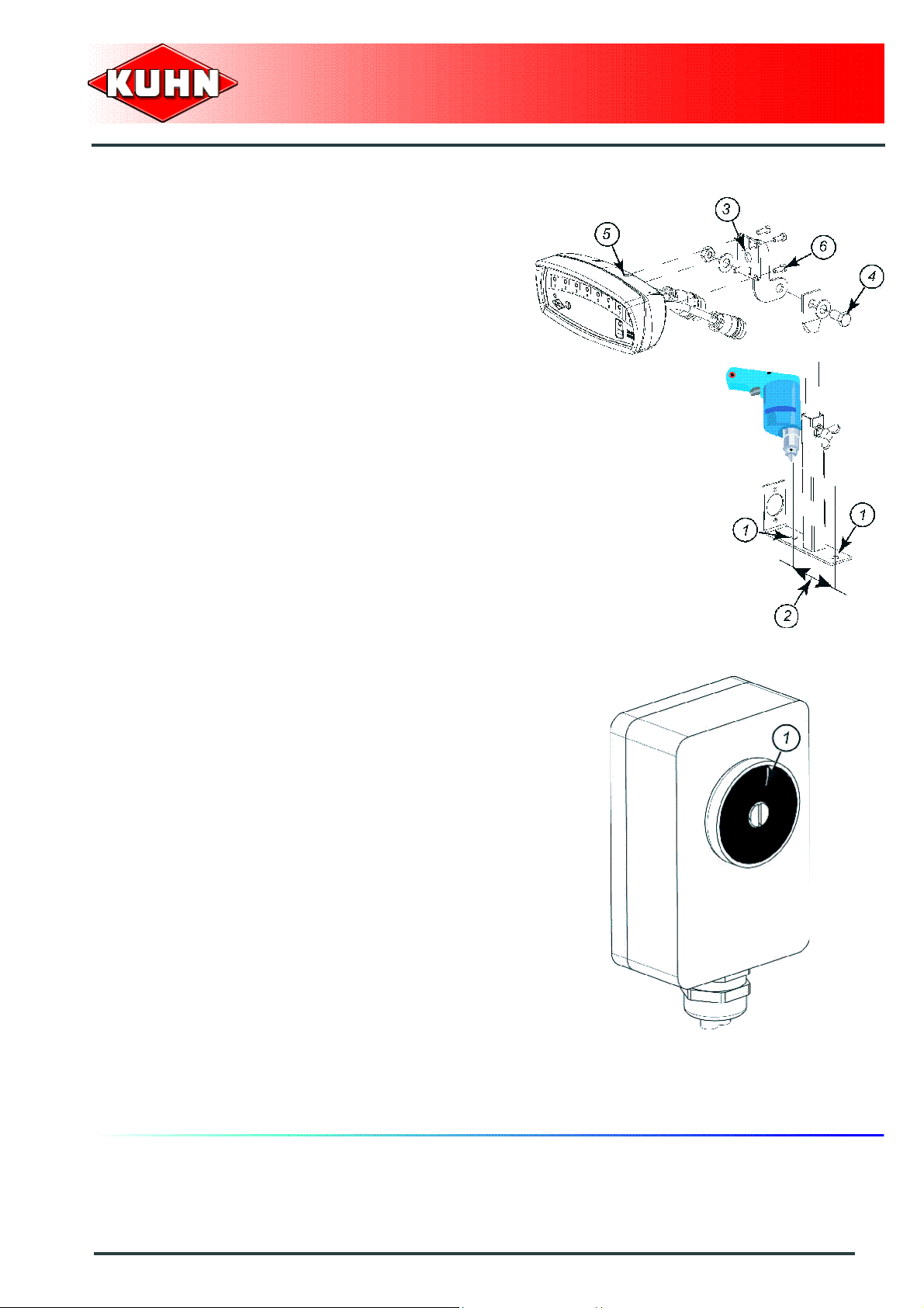
Fitting the control boxes
The control boxes must be easy to access from the
tractor cab.
Control boxes KMS412/KMS208 and KMD112:
- Drilling of 2 holes diameter 11 mm (1).
- 100 mm Hole to hole distance (2).
- Fit holder (3) using screws, washers and nuts (4).
- Position control box (5) using screws (6).
Precision Seed Drills
MAXIMA 2
Control box HECTOR 3000:
The attachment is ensured by magnet (1).
Removing the control boxes
The control boxes must be stored in a dry place free of
dust.
Putting into service
55
Page 58

3 pin plug
The box is energized by the tractor's 3-pin socket(DIN
9680, ISO 12369) or the battery power cable supplied.
Pin Wire color Function
15 / 30 (1) Brown + 12 Volt
31 (2) Blue Earth
82 (3) - -
Precision Seed Drills
MAXIMA 2
Description of the connection
Never connect battery charger or perform
welding tasks without having previously
disconnected the control box.
The control boxes are connected to:
- A tractor 3-pin socket.
- a supplied battery power cable.
To use the machine with another tractor, a
second tractor-side power harness can be
ordered under p/n 83233001.
Do not connect the wiring harness to the
starter connections.
Check that the connectors are in a good
condition and clean.
If the tractor is not fitted with a battery isolation switch:
Connect the wiring harness directly to the battery
terminals respecting the polarities.
If the tractor is fitted with a battery isolation switch:
Connect the wiring harness to the battery isolation
switch output.
The wiring harness is fitted with a 15 Amp ATO type
fuse: Part no. 82333017(2).
+
-
56
Putting into service
Page 59

3. Coupling and uncoupling
Description of coupling elements
The machine is equipped with:
- 1 PTO shaft 1 3/8’’ - 6 splines.
- 1 3-pin socket.
- 1 7-pin plug for the signalling equipment.
- 2 hydraulic hoses to supply the side marker cylinders.
Precision Seed Drills
MAXIMA 2
When optional equipment is used, follow
specific procedures mentioned in the related
section: Filling auger.
Preparing the tractor
The machine is for use with tractors equipped with a
standard category 2 or 3 3-point hitch.
The tractor must be fitted with a double acting hydraulic
outlet.
Putting into service
57
Page 60

The tractor PTO stub must rotate at a speed of 540 min-1.
Belt and pulley assemblies are available to adapt
the blower speed to the tractor PTO speed.
- 470 min
-1
pulley and belt unit: Kit
no. 1677287
- 870 min
-1
pulley and belt unit: Kit
no. 1676731
- 1000 min
-1
pulley and belt unit: Kit
no. 1676738
Precision Seed Drills
MAXIMA 2
The front axle load (1) must never, under any
circumstances, be less than 20% of the
tractor's unladen weight.
The tractor must be fitted with lower link
stabilizers.
Fitting a pull bar
A pull bar must be fitted when the machine is
equipped with a semi-automatic attachment
category 2.
- Fit pull bar (1) on lower links (2).
- Install spacer (3).
- Insert and lock lynch pin (4).
Proceed the same way on the other side.
58
Putting into service
Page 61

Lateral adjustment of the lower linkage arms
Balance the play on either sides of the lift linkage and
lock lower link stabilizers.
Parallelism of lower linkage arms
Adjust tractor lift rods so that lower linka ge arms are at
equal height from ground.
Precision Seed Drills
MAXIMA 2
Placing the tractor lift linkage in floating position
Adjust turn buckles (1) in order to obtain floating position
of the lower link arms.
This position enables free machine adaptation to the
ground contours.
Putting into service
59
Page 62

Tyres
If compatible with the seed drill configuration, we
recommended fitting the tractor with dual wheels or
extra-wide wheels in order to reduce the ground
pressure.
Make sure that the seed drill never interferes
with the tractor wheels.
Precision Seed Drills
MAXIMA 2
Tractor tire pressure
To ensure that tractor can be driven safely and that
machine gives the desired finish, each tyre must be
inflated to the correct pressure for the load supported.
- Slightly lift the machine from the ground.
- Measure the load on each wheel (or the load of one
axle divided by 2) using a weight indicator or a scale.
- Refer to the tyre manufacturer's pressure chart.
- Adjust the tyre pressure to the measured loads.
The tyre pressure must be identical on each side of the
tractor.
60
Putting into service
Page 63

Coupling the machine
For attachment category 2:
- Position hitch bar closest to the semi-automatic
attachment.
- Remove lynch pins (1) (1 on each machine side).
Precision Seed Drills
MAXIMA 2
- Raise tractor lower links to engage hitch bar (1) in th e
machine's semi-automatic attachment (2).
- The lock (3) automatically engages.
- Insert and lock lynch pin (4). (1 on each machine
side).
- Attach top link with hitch pin.
- Use tractor and machine attachment holes to adjust
the top link position.
- Raise machine using the tractor lift linkage until
parking stands no longer rest on the ground.
To obtain optimum PTO shaft angles and
tractor lift capacity, the top link must be
parallel to the lower links or slightly pointing
downwards towards the tractor.
Putting into service
61
Page 64

- Remove lynch pin (1) and pin (2).
- Raise parking stand (3).
- Insert pin (2) and lock using lynch pin (1).
- Repeat procedure on the other parking stand.
For attachment category 3:
- Lower the tractor three-point linkage.
- Position ball joints of tractor lower links in line with
holes of machine lower yokes.
- Insert pins (1) and lock using lynch pins (2).
Precision Seed Drills
MAXIMA 2
- Remove lynch pin (1) and pin (2).
- Raise parking stand (3).
- Insert pin (2) and lock using lynch pin (1).
- Proceed the same way on each parking stand.
62
Putting into service
Page 65
- Attach top link with hitch pin.
- Use tractor and machine attachment holes to adjust
the top link position.
- Raise machine using the tractor lift linkage until
parking stands no longer rest on the ground.
To obtain optimum PTO shaft angles and
tractor lift capacity, the top link must be
parallel to the lower links or slightly pointing
downwards towards the tractor.
Precision Seed Drills
MAXIMA 2
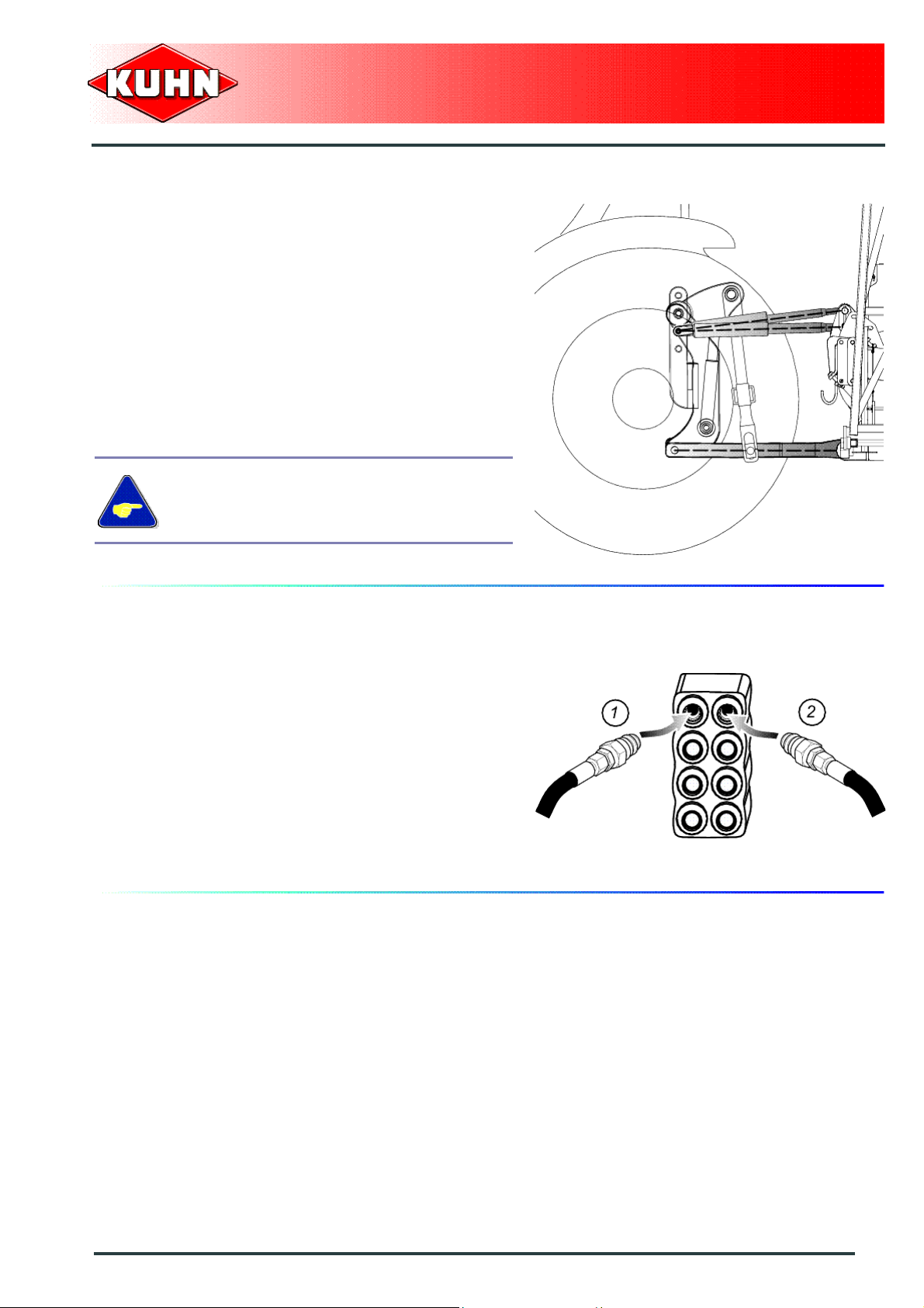
Hydraulic connections
Connect hydraulic hoses (1) and (2) to a double acting
outlet.
Hoses (A) and (B) supply the side marker
folding/unfolding cylinders.
Putting into service
63
Page 66

Adjusting the machine
Adjusting the vertical setting
Adjust the top link length so that the machine is
horizontal with regards to the ground.
This setting can be checked with the seed drill level
gauge (1).
Check setting over the first few metres sown.
Precision Seed Drills
MAXIMA 2
Adjusting the scrapers of the side gauge wheels
The scrapers remove soil build-up on the rubber tread of the side gauge wheels.
- Loosen bolts (1).
- Adjusting scrapers (2):
Lateral adjustment
Adjust scraper to obtain play (X) of approximately 3 mm
(0.12 ’’) between scraper (2) and the inside rubber tread
of gauge wheel (3).
Lengthways adjustment
Adjust scraper (2) as close as possible to the gauge
wheel, without touching it. Rotate gauge wheel once to
check that it is not in contact.
- Tighten screws (1).
In certain wet conditions with plant debris, it may
be necessary to remove the scrapers to continue
working without risking stopping the gauge
wheels from turning.
64
Putting into service
Page 67

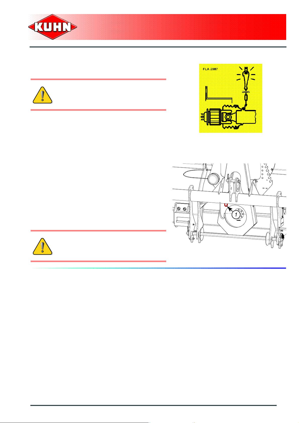
Setting the seed row spacing
For machine with 8 - 12 - 18 rows.
Adjusting the central sowing units:
- Raise machine using tractor lift.
- Measure the frame middle.
- Loosen nuts (1).
- Adjust position of the two central sowing units in order
to obtain a spacing (D) with regards to the frame
middle equalling half of spacing (E) required between
rows.
- Tighten nuts (1).
• Torque: 13 daN m (96 lbf ft).
Precision Seed Drills
MAXIMA 2
Setting sowing components:
- Loosen nuts (1).
- Adjust position of the seeding units to obtain required
spacing (E) between rows.
- Tighten nuts (1).
• Torque: 13 daN m (96 lbf ft).
Repeat procedure on each seeding unit.
For machine with 9 - 11 rows.
Setting sowing components:
- Raise machine using tractor lift.
- Measure the frame middle.
- Check that central unit (1) is positioned in the frame
middle.
- Loosen nuts (2).
- Adjust position of the seeding units to obtain required
spacing (E) between rows.
- Tighten nuts (2).
• Torque: 13 daN m (96 lbf ft).
Repeat procedure on each seeding unit.
Putting into service
65
Page 68
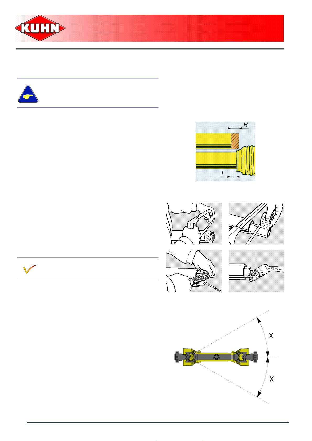
Primary PTO shaft
Make sure that the PTO shaft is correctly
adjusted, to avoid premature wear and tear.
Separate the two half PTO shafts and connect them to
the machine's input shaft and to the tractor PTO stub.
Check the length of the PTO shaft:
- When the PTO shaft is in its maximum overlap
position (retracted), tubes should not butt against the
yokes.
- As a safety measure, a clearance (L) of at least
25 mm (1’’) must be maintained.
- When the PTO shaft is in its maximum extended
position, the tube overlap must be more than
250 mm (10’’).
Precision Seed Drills
MAXIMA 2
If this is not the case:
- Mark length (H) to cut when the transmission is the
maximum overlap position.
- Shorten the guard tubes and the transmission tubes
by the same length.
- Bevel and clean the tubes.
- Grease the inside of the outer tube.
Check that there is still a minimum overlap of
250 mm (10’’) when the machine is in working
position and the tractor in line with the machine.
Never operate the PTO shaft at an angle X exceeding
30°.
66
Putting into service
Page 69
To avoid serious accidents, the PTO drive
shaft guards must be properly in place and
fixed with the chains provided.
Precision Seed Drills
MAXIMA 2
On machine side, hook drive guard chain to ring (1).
Immediately replace any worn or damaged
guard.
Putting into service
67
Page 70

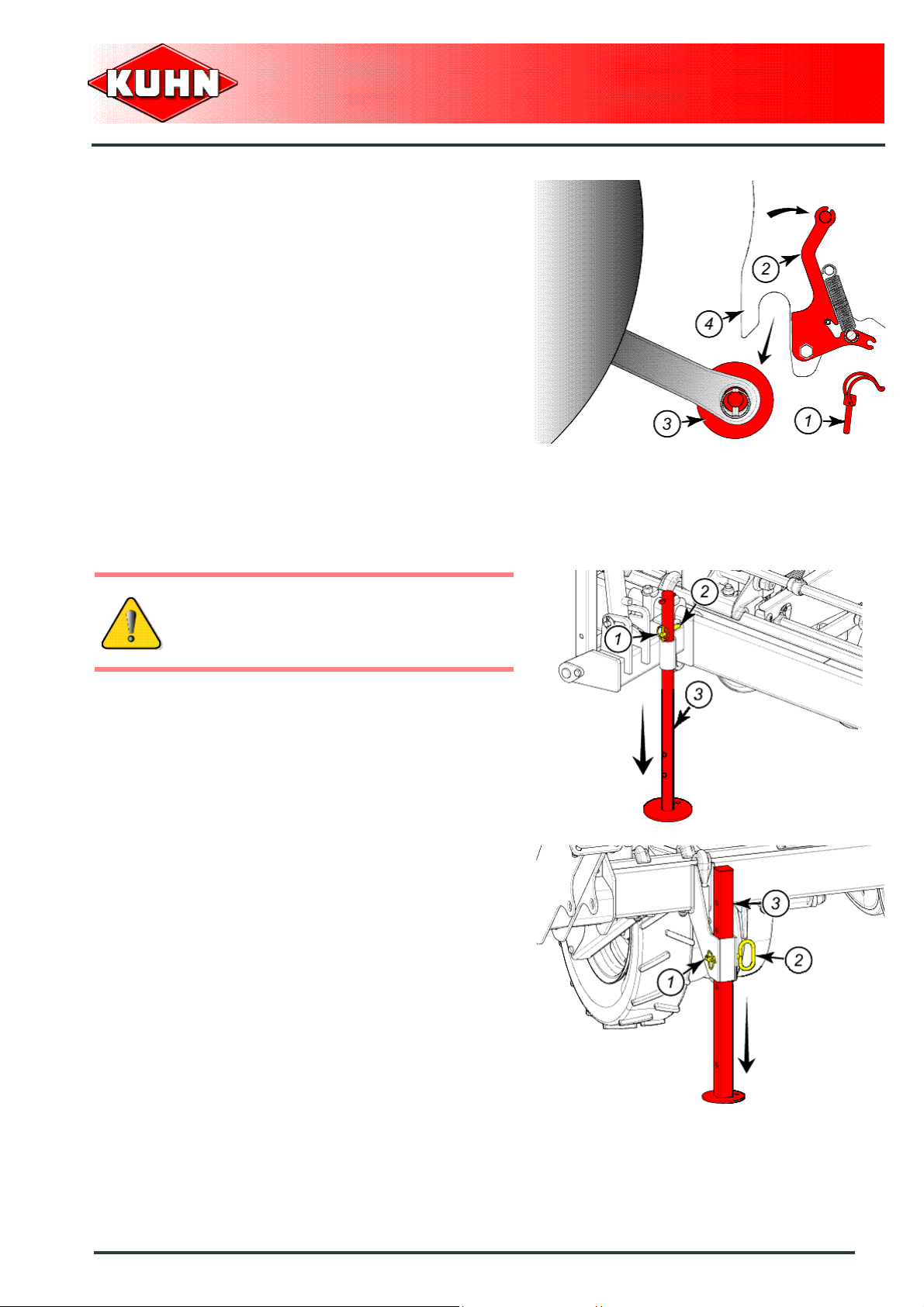
Uncoupling the machine
For attachment category 2:
Park the machine on an even fairly level
ground.
- Remove lynch pin (1) and pin (2).
- Lower parking stand (3).
- Insert pin (2) and lock using lynch pin (1).
- Repeat procedure on the other parking stand.
Precision Seed Drills
MAXIMA 2
- Lower the tractor three-point linkage to rest the
machine on the ground.
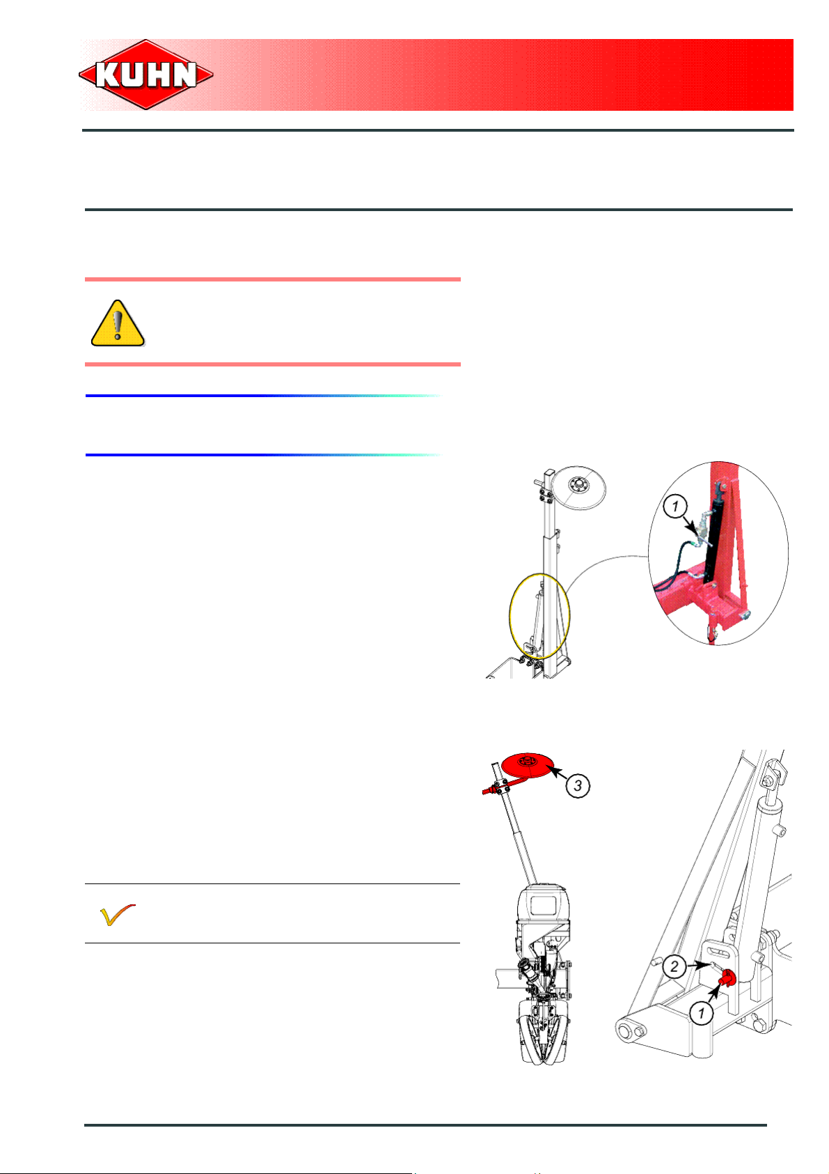
- Uncouple and place PTO shaft in support (1).
- Disconnect and store hydraulic hoses in holder (2).
- Disconnect and store control boxes in a dry and clean
place.
- Detach the top link from the machine end.
68
Putting into service
Page 71
- Remove lynch pins (1) (1 on each machine side).
- Pivot lock (2).
- Lower tractor lower links to disengage hitch bar (3)
from the machine semi-automatic attachment (4).
- Insert and lock lynch pin (1) (1 on each machine side).
The machine is uncoupled.
Precision Seed Drills
MAXIMA 2
For attachment category 3:
Park the machine on an even fairly level
ground.
- Lower parking stands:
• Remove lynch pin (1).
• Lower parking stand (2).
• Insert and lock lynch pin (1).
• Repeat procedure on the other parking stand.
Putting into service
69
Page 72

- Lower the tractor three-point linkage to rest the
machine on the ground.
- Uncouple and place PTO shaft in support (1).
- Disconnect and store hydraulic hoses in holder (2).
- Disconnect and store control boxes in a dry and clean
place.
- Detach the top link from the machine end.
- Remove lynch pins (2).
- Remove the 2 pins (1).
- Lower the tractor three-point linkage.
Precision Seed Drills
MAXIMA 2
The machine is uncoupled.
70
Putting into service
Page 73
$INSTRUCTIONS FOR TRANSPORT
Before placing the machine into transport
position:
Wait until the rotating parts have come to a
complete stop.
1. Putting the machine into transport position
Precision Seed Drills
MAXIMA 2
From the working position:
If the machine is fitted with a fertilizer or if the
machine is fitted with a fertilizer with a 1350 L
(356 US gal) hopper:
- Activate cylinders to fold side markers.
- Lock side markers using valves (1) (1 on each
marker).
- Position pin (1) in lower hole (2).
this position enables leaving the marker disks (3)
pointing outwards.
Instructions for transport
71
Page 74

If the machine is equipped with a fertilizer with
2x280 l (2x74 US gal) hoppers:
- Activate cylinders to fold side markers.
- Lock side markers using valves (1) (1 on each
marker).
- Remove tube clip (1).
- Position side marker disc towards the machine inside.
- Insert and lock tube clip (1).
Repeat procedure for the other marker.
Precision Seed Drills
MAXIMA 2
- Position pin (1) in upper hole (2).
The machine is in transport position.
Never engage the tractor PTO drive when th e
machine is in transport position.
72
Instructions for transport
Page 75

2. Conformity with the road regulations
For driving on public roads, due to its width,
the machine must be transported on a trailer.
Check that the lilght boards are clean and that the
lighting equipment functions before transporting the
machine on public roads.
Immediately replace any worn or damaged
signalling panels or lights.
Precision Seed Drills
MAXIMA 2
During transport, adapt the travel speed to
suit the road conditions.
Instructions for transport
73
Page 76

$INSTRUCTIONS FOR WORK
Before placing the machine in working
position:
- Check that nobody is within the machine
pivoting area.
- If there is someone, make sure the
person moves away.
1. Putting the machine into work position
Precision Seed Drills
MAXIMA 2
From the transport position:
If the machine is equipped with a fertilizer with
2x280 l (2x74 US gal) hoppers:
- Lower tractor lift linkage to position the machine near
to the ground.
- Remove tube clip (1).
- Position side marker disc on the machine outside.
- Insert and lock tube clip (1).
Repeat procedure for the other marker.
- Unlock side marker valve (1). (1 on each marker).
- Deploy the right or left side marker.
The machine is in working position.
74
Instructions for work
Page 77

2. Adjustments in working position
Adjusting the seeding unit ground
pressure
The seeding unit ground pressure is modified by
changing the position of springs (1).
Precision Seed Drills
MAXIMA 2
Coupling device (a):
By moving one spring (1) rearwards, the seeding unit
ground pressure is increased by 20 kg (44 lb).
Coupling device (b):
By moving 2 springs (1) rearwards, the seeding unit
ground pressure is increased by 40 kg (88 lb).
When the 2 springs (1) are positioned in
configuration (b), check that the frame is
sufficiently ballasted.
The drive wheels must not slip. If necessary
ballast the frame.
Instructions for work
75
Page 78

Whe the machine is fitted with electronic
seeding unit disengagement system (1),
never position springs (2) in configuration
(c). There is a risk of interference.
Precision Seed Drills
MAXIMA 2
76
Instructions for work
Page 79

Adjusting the sowing depth
Handle (1) enables adjusting the sowing depth.
The sowing depth can be adjusted from 0 to
8.5 cm (0’’ - 3.34’’) (app ro xim a te ly).
Precision Seed Drills
MAXIMA 2
Adjustment:
Refer to the decal applied on the machine to determine
handle (1) setting position.
Settings are only indicated for your
information.
The seeding unit setting must be adjusted
according to the sowing conditions (Soil
preparation and nature).
Example:
To adjust the sowing depth at 4.5 cm (1.77’’), place
adjustment handle in position D-E.
- Repeat procedure on each seeding unit.
The marking enables identical setting of each
seeding unit.
Instructions for work
77
Page 80
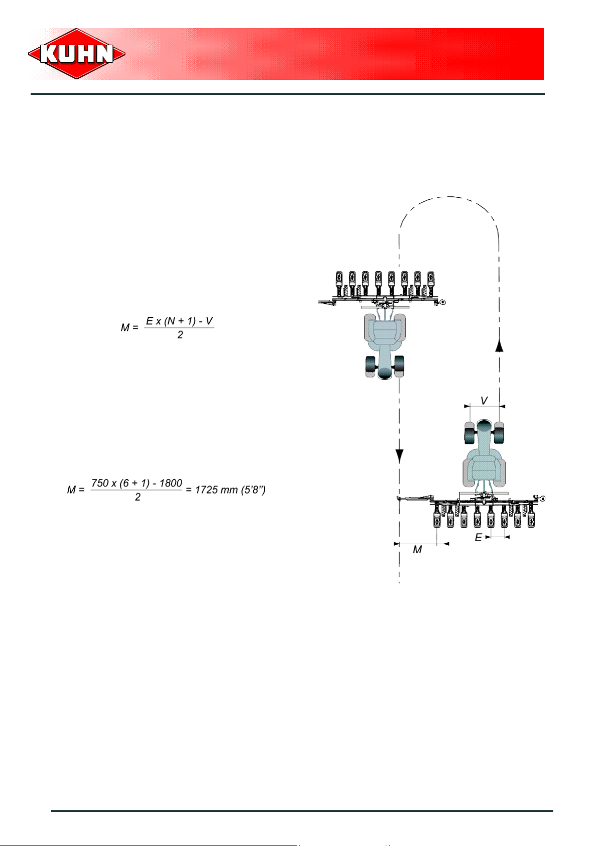
Adjusting the markers
The side markers are designed to provide marking in the
tractor center or wheel track.
Marking to the tractor wheel
Calculating the distance (M):
- M: distance between the marker disk and the outer
seeding unit.
- N: Number of rows.
- E: distance between rows.
- V: Tractor wheel track.
Precision Seed Drills
MAXIMA 2
Example:
N = 6 rows
E = 750 mm (2.5’’)
V = 1800 mm (5’11’’)
78
Instructions for work
Page 81

Marking in line with the tractor
Calculating the distance (M):
- M: distance between the marker disk and the outer
seeding unit.
- N: Number of rows.
- E: distance between rows.
Example:
Precision Seed Drills
MAXIMA 2
N = 6 rows
E = 750 mm (2.5’’)
Instructions for work
79
Page 82
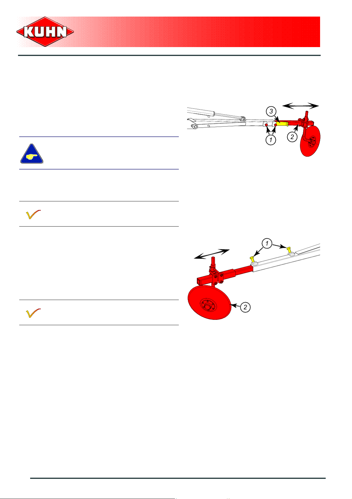
Adjusting the length (M)
- Unscrew the 2 bolts (1).
- Move side marker extension (2) to obtain required
length M.
- Check that spacer (3) located between the rigid arm
and the pivoting arm is fully inside the rigid arm.
The spacer prevents deterioration of the
moving arm when tightening the screws.
- Tighten bolts (1).
Repeat procedure on the second side marker.
Precision Seed Drills
MAXIMA 2
You are recommended to check this setting in
the field, by inspecting several runs.
For models 9 m (29’6’’):
- Unscrew the 2 bolts (1).
- Move side marker extension (2) to obtain required
length M.
- Tighten bolts (1).
Repeat procedure on the second side marker.
You are recommended to check this setting in
the field, by inspecting several runs.
80
Instructions for work
Page 83

Angle adjustment
- Loosen U-bolts (1).
- Pivot arm (2) to adjust the disc angle with regards to
the soil type.
- Tighten U-bolts (1).
Repeat procedure on the second side marker.
Precision Seed Drills
MAXIMA 2
For models 9 m (29’6’’):
- Loosen U-bolts (1).
- Pivot arm (2) to adjust the disc angle with regards to
the soil type.
- Tighten U-bolts (1).
Repeat procedure on the second side marker.
Instructions for work
81
Page 84

Selection of disks
Never drill out disks in order to increase the
diameter of the intake holes, otherwise
serious deterioration of sowing accuracy
may result.
For Maize seeds
In general, use disks with holes of diameter 5 mm (0.2 ’’)
for maximum versatility (Standard supplied).
Maize seeds with very angular or pointed shapes can be
sown with a disk with 4.5 mm (0.17 ’’) diameter holes to
improve seed placement in the row.
Precision Seed Drills
MAXIMA 2
For sowing very large maize seeds, we recommend
using a disk with 5.5 mm (0.21 ’’) diameter holes.
For sowing very small sweet corn seeds, we recommend
using a disk with 3.5 mm (0.14 ’’) diameter holes.
For Sunflower seeds
Successful sunflower sowing depends on two factors:
- The adaptation of the disk hole diameter to the seed
size.
- The selector adjustment.
Indications on the seed bags do not mention the
seed size.
We recommend to possess 2 disk models (holes
diameter 2.5 mm (0.1 ’’) and 3.5 mm (0.14 ’’)) if
the seed size to be purchased cannot be
specified.
82
Instructions for work
Page 85
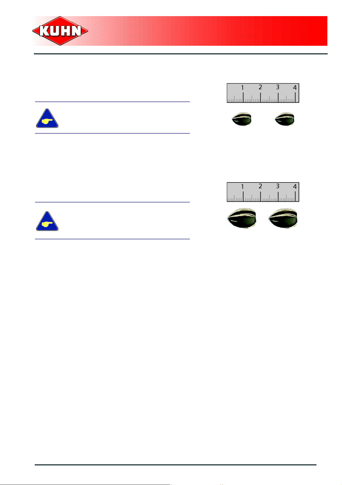
Fine and medium Sunflower
For sowing fine or medium sunflower seeds, we
recommend using a disk with 2.5 mm (0.1 ’’) diameter
holes.
For sowing fine or medium sunflower seeds,
using a disk with 3.5 mm (0.14 ’’) diameter
holes does not enable fine tuning of the
selection (Too many misses or doubles).
Coarse Sunflower
For sowing large sunflower seeds, we recommend using
a disk with 3.5 mm (0.14 ’’) diameter holes.
Precision Seed Drills
MAXIMA 2
For sowing large sunflower seeds, using a
disk with 2.5 mm (0.1 ’’) diameter holes does
not enable fine tuning of the selection
(Correct positioning but with too much
misses).
Instructions for work
83
Page 86

Table of recommended distribution disks
Precision Seed Drills
MAXIMA 2
Type of seeds Number of holes Hole diameter (mm)
Maize 27 5.0 from 8 to 24.1
Maize 27 4.5 from 8 to 24.1
Maize 27 5.5 from 8 to 24.1
Maize 22 5.0 from 9.8 to 29.5
Maize 22 4.5 from 9.8 to 29.5
Maize 22 5.5 from 9.8 to 29.5
Sunflower 18 2.5 from 12 to 36.1
Sunflower 18 3.5 from 16 to 36.1
Bean 48 3.5 from 4.5 to 13.5
Bean 48 2.5 from 1.5 to 13.5
Sorghum 70 2.5 from 3.1 to 9.3
Beet 31 2.1 from 7 to 21
Beet 22 2.1 from 9.8 to 29.5
Soy 70 4.5 from 3.1 to 6.3
Min/max spacing
(cm)
Delinted cotton 33 3.5 from 6.5 to 19.7
84
Instructions for work
Page 87
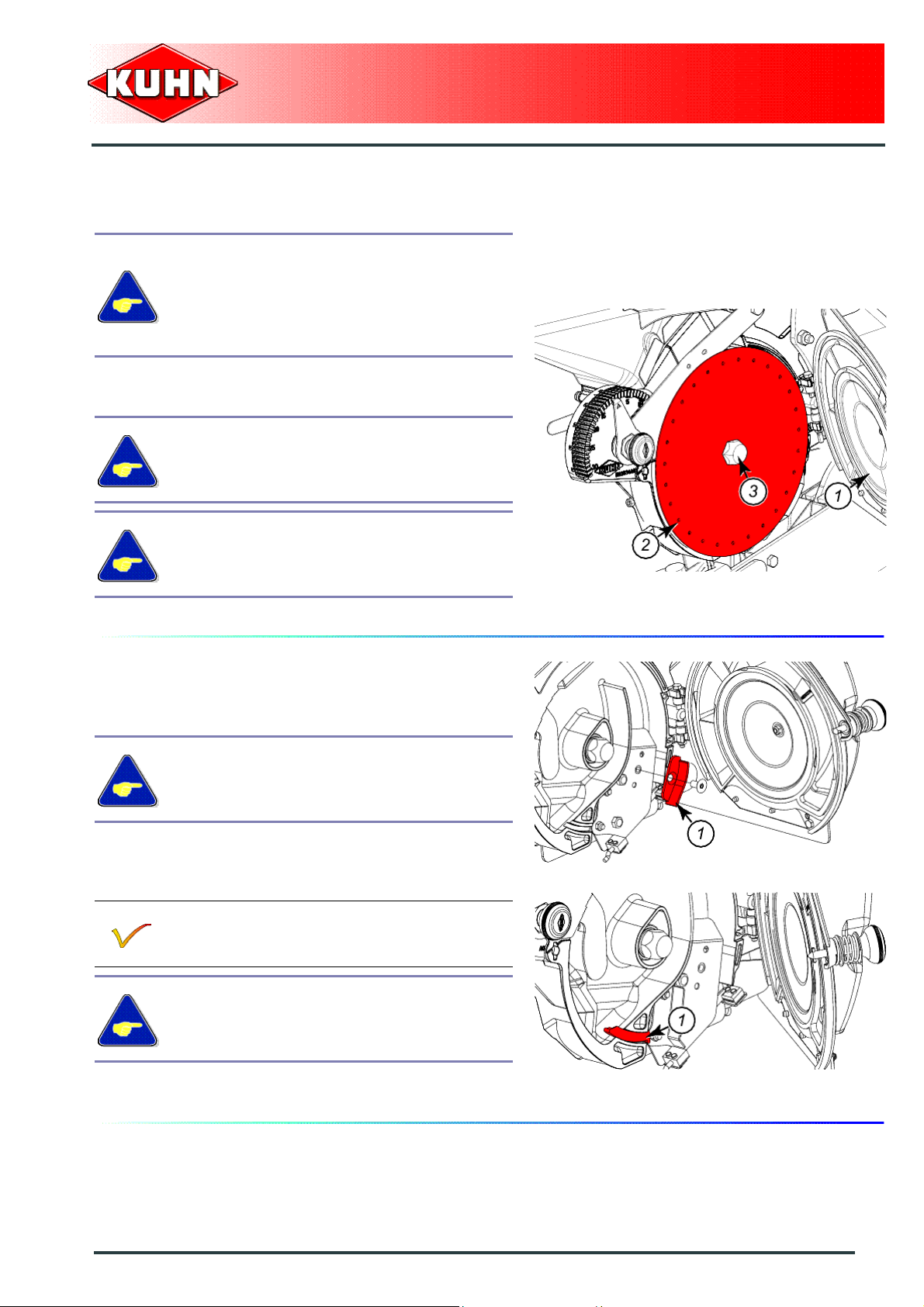
Fitting distribution disks
Before changing a disk, empty the seeding
unit hopper.
Mark disks prior to removing them in order to
determine their respective position. A disk
must always be fitted on the same sowing
unit.
- Open hood (1).
- Install distribution disk (2) on drive shaft ( 3).
When disks are fitted with agitator blades,
position disks with agitator blades pointing
inwards.
Precision Seed Drills
MAXIMA 2
Check that the distribution disk is properly
positioned on the drive shaft.
- Close hood (1).
Selecting and fitting seed ejectors
When the machine is used with disks with only one row
of holes, the ejector BNB0083 (1) must be fitte d.
This ejector must always be fitted whatever
the seed variety.
When disks are not fitted with agitator blades, install
spacer BNB0048 (1).
The agitator blades fitted on the disk enable
preventing seed bridging in the casing.
Spacer BNB0048 stops small seeds from
flowing freely through the groove.
When the disks are fitted with agitator blades, spacer
BNB0048 (1) must be removed.
Instructions for work
85
Page 88
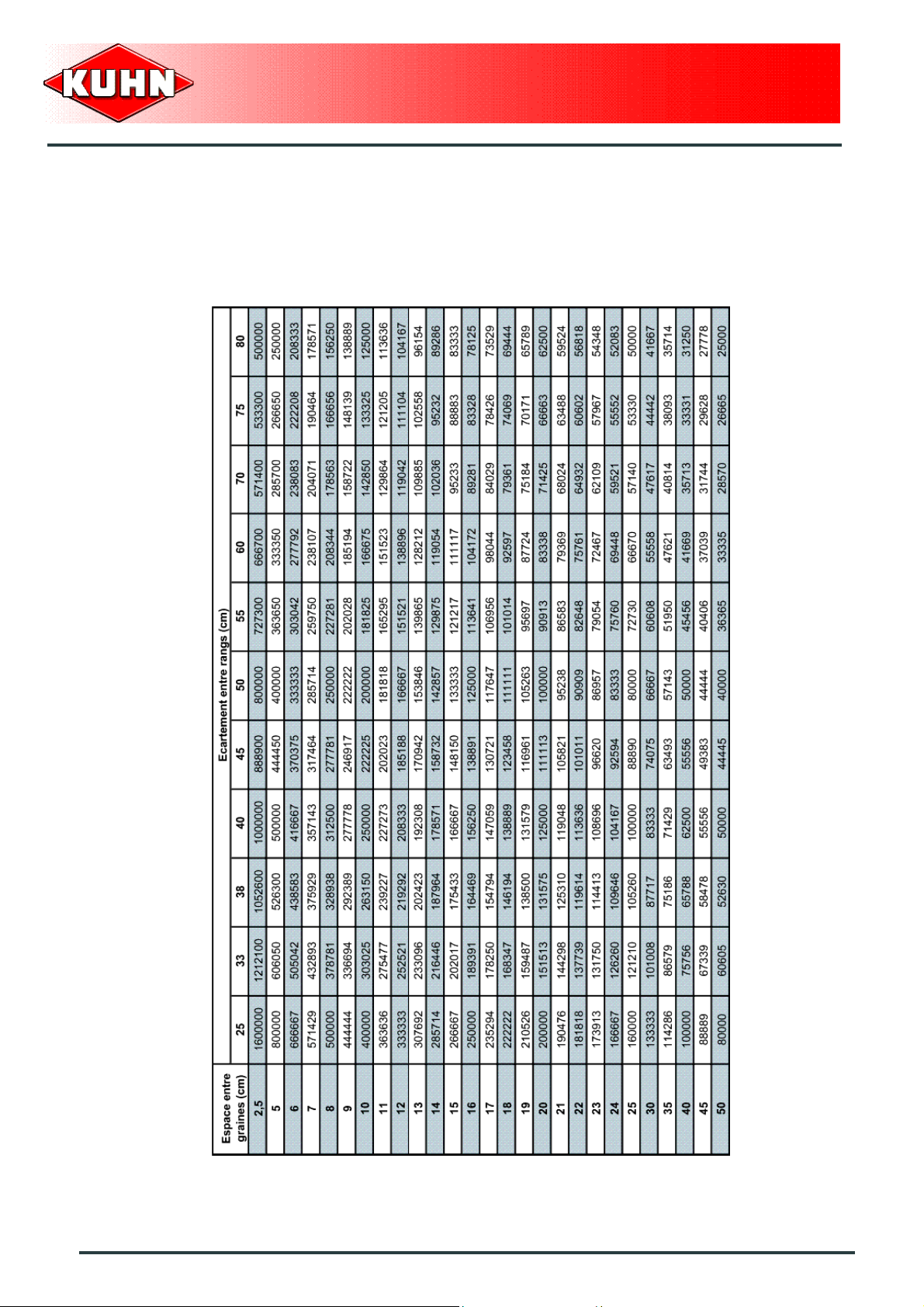
Adjusting the number of plants per hectare
Number of plants per hectare according to spacing between seeds and between rows
Precision Seed Drills
MAXIMA 2
86
Instructions for work
Page 89

Distribution output charts
Precision Seed Drills
MAXIMA 2
Instructions for work
87
Page 90

Precision Seed Drills
MAXIMA 2
88
Instructions for work
Page 91

Precision Seed Drills
MAXIMA 2
Instructions for work
89
Page 92

Precision Seed Drills
MAXIMA 2
90
Instructions for work
Page 93

Precision Seed Drills
MAXIMA 2
Instructions for work
91
Page 94

How to read the calibration charts
Use the chart corresponding to the selected disk type
(According to the number of holes).
The chart enables determining the position of the
gearbox gearwheels according to the spacing between
the seed drill rows and the number of plants required per
hectare.
Example:
For Maize seeds: 27 hole disk.
Seed row spacing: 75 cm (2’5’’).
Required population: 83000 plants/hectare.
Precision Seed Drills
MAXIMA 2
To obtain a number of plants (1) close to the required
number with a spacing between rows (2) of 75 cm (2’5’’),
position gearbox gearwheels on ratio D1 (3).
The chart also indicates the spacing between
seeds (4) and the theoretical number of seeds
(5) over 1 m (3’3’’).
It is possible to determine the gearbox ration as
from this data.
If in between 2 values in the adjustm ent chart,
select the setting that gives the less plants per
hectare.
92
Instructions for work
Page 95

When the chart does not correspond to the disk used
(number of holes), use "1 hole disk" chart:
Precision Seed Drills
MAXIMA 2
The 1 hole disk chart enables determin ing the following
values:
- Number of plants per hectare.
- Spacing between seeds.
- Number of seeds per meter.
Example:
Seed row spacing: 75 cm (2’5’’).
24 hole disk.
Selected speed ratio: A1
Number of plants per hectare:
P = Number of plants per hectare.
N = Number of holes on the disk used.
N1 = Number of seeds with 1 hole disk.
P = (N x N1) x1000
Example:
P = (24 x 6.17) x 1000 = 148080 seeds/ha
Instructions for work
93
Page 96

Spacing between seeds:
E = Spacing between seeds.
E1 = Spacing between seeds with 1 hole disk.
N = Number of holes on the disk used.
E = E1 / N
Example:
E = 2161 / 24 = 90 mm (3.5’’)
Number of seeds per meter:
N1 = Number of seeds per meter.
N2 = Number of seeds per meter with 1 hole disk.
N = Number of holes on the disk used.
Precision Seed Drills
MAXIMA 2
N1 = N2 x N
Example:
N1 = 0.463 x 24 = 11.1 Seeds per meter.
94
Instructions for work
Page 97
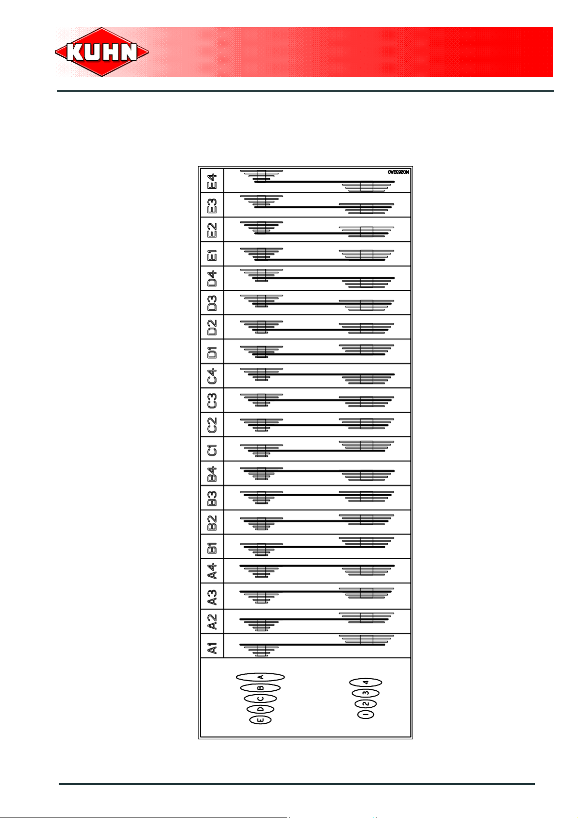
Adjustment of the gearbox
Combination chart
Precision Seed Drills
MAXIMA 2
Instructions for work
95
Page 98

Adjust gearbox gearwheel and chain position according
to the ratio recommended in the calibration chart.
Example:
Ratio to adjust: D1.
Precision Seed Drills
MAXIMA 2
- Position chain on upper level gearwheel D.
- Position chain on lower level gearwheel 1.
Variation of 6 % between each ratio.
96
Instructions for work
Page 99
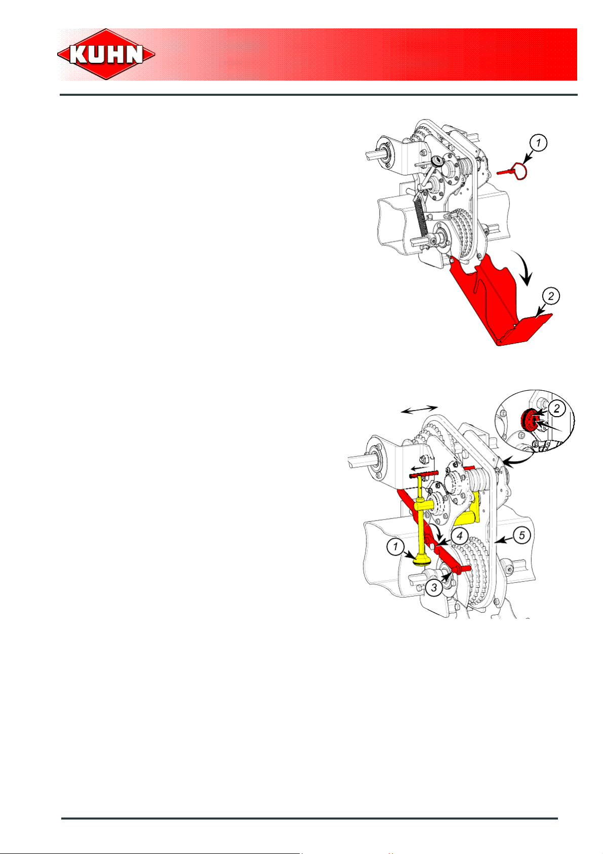
Adjustment:
- Remove lynch pin (1).
- Open gearbox (2).
Precision Seed Drills
MAXIMA 2
- Lower lever (1) until chain tension is loosened.
- Push handle (2) to lock lever (1) in low position.
- Position lever (3) in notch (4) to enable moving the
upper level gearwheels sideways.
- Position chain (5) on the recommended gearwheels.
Instructions for work
97
Page 100

- Position lever (3) in notch (4) to lock upper level
gearwheels.
Check that chain and gearwheels are in line.
- Maintain lever (1) downwards and pull handle (2) to
unlock the lever.
- Lift lever (1) to retension the chain.
Precision Seed Drills
MAXIMA 2
- Close gearbox (1).
- Insert and lock lynch pin (2).
98
Instructions for work
 Loading...