

Page 1

Complementary instructions
KC0010GB H
Conventional seed drills
INTEGRA G2 \ PREMIA
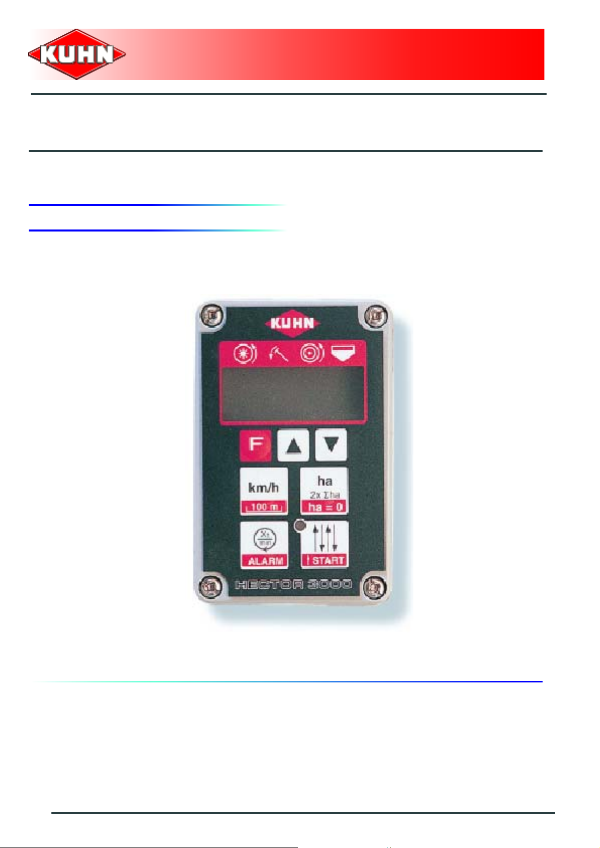
HECTOR 3000
KC0010GB H
- English - 01-2010
Page 2

Page 3

INTEGRA G2 \ PREMIA
HECTOR 3000
$Dear Owner
In buying a Kuhn machine you have chosen wisely. Into it have gone years of thought, research and
improvement. You will find, as have thousands of owners all over the world, that you have the best that
engineering skill and actual field testing can produce. You have purchased a dependable machine, but only
through proper care and operation can you expect to receive the performance and long service built into it.
This manual contains all the necessary information for you to receive full efficiency from your machine. The
performance you get from this machine is largely dependent on how well you read and understand th is manual
and apply this knowledge. Please DO NOT ASSUME YOU KNOW HOW TO OPERATE AND MAINTAIN YOUR
MACHINE before reading this manual carefully. KEEP THIS MANUAL AVAILABLE FOR REFERENCE. Pass
it on to the next owner if you re-sell the machine.
Your KUHN dealer can offer a complete line of genuine KUHN service parts. These parts ar e manufactured and
carefully inspected in the same factory that builds the machine to assure high quality and accurate fitting of any
necessary replacements.
About improvements
We are continually striving to improve our products. It therefore reserves the right to make improvements or
changes when it becomes practical to do so, without incurring any obligations to make changes or additions to
the equipment sold previously.
Dear Owner
1
Page 4

INTEGRA G2 \ PREMIA
HECTOR 3000
$Contents
Dear Owner.....................................................................................................................1
Contents..........................................................................................................................2
Control box identification..............................................................................................4
Front view..........................................................................................................................................4
Manufacturers' marking.................... ... .... ... ... ... ... .... ... ............................................. ... .... ... ... ...........5
Optional equipment..........................................................................................................................5
Safety...............................................................................................................................6
Description of symbols used in this document.............................................................................6
Safety instructions...........................................................................................................................7
Specifications.................................................................................................................9
Technical specifications............. ... ... ... .... ... ... ... ... .... ............................................. ... ... .... ... ..............9
Description of the box....................................................................................................................10
Meaning of symbols.......................................................................................................................11
Description of the controls............................................................................................................11
Assembly and fitting....................................................................................................14
Description of the connection.......................................................................................................14
Electrical diagrams.........................................................................................................................17
Positioning and parking.................................................................................................................20
2
Contents
Page 5

INTEGRA G2 \ PREMIA
HECTOR 3000
Putting into service .....................................................................................................21
Switches on the control box . ........................................................................................................21
Machine use .................................................................................................................22
Adjustments before first use.........................................................................................................22
Preliminary adjustments at work..................................................................................................27
Use during work.............................................................................................................................44
Simple maintenance....................................................................................................47
Error codes.....................................................................................................................................47
Adjusting the sensors....................................................................................................................48
Optional equipment.....................................................................................................49
Additional hopper bottom sensor (INTEGRA G2 from A0001 to C9999)...................................49
Additional hopper bottom sensor (INTEGRA G2 from D0000 to .....) ........................................49
Sensor holder on wheel arm (INTEGRA GII)................................................................................50
Shunt (PREMIA).................................... ... ... .... .......................................... ... ... ... .... ... ... ... ................50
Maintenance and storage............................................................................................ 51
Limited warranty.......................................................................................................... 52
Contents
3
Page 6
1. Front view
INTEGRA G2 \ PREMIA
HECTOR 3000
$Control box identification
4
Control box identification
Page 7

2. Manufacturers' marking
Please note the serial number of your equipment. This
information is to be indicated to the dealer for all spare
parts orders.
Type:
Serial no.:
KUHN reference:
The software version: 2.2
INTEGRA G2 \ PREMIA
HECTOR 3000
3. Optional equipment
Tick box corresponding to the equipment fitted on your
machine:
On: INTEGRA G2 (from A0001 to C9999)
Additional hopper bottom sensor
Sensor holder on wheel arm
On: INTEGRA G2 (from D0000 to .....)
Additional hopper bottom sensor
Sensor holder on wheel arm
On: PREMIA
Shunt
Control box identification
5
Page 8
$Safety
1. Description of symbols used in this document
This symbol indicates a potentially hazardous situation
that if not avoided, could result in serious bodily injury.
INTEGRA G2 \ PREMIA
HECTOR 3000
This symbol is used to identify special instructions or
procedures which, if not followed strictly, could result in
machinery damage.
This symbol is used to communicate technical
information of particular interest.
6
Safety
Page 9
INTEGRA G2 \ PREMIA
HECTOR 3000
2. Safety instructions
Introduction
The operator must follow the safety instructions in this manual and in the machine's operator's manual as well
as respect the warnings posted on the machine.
Read and follow the safety instructions
Before using the control box, carefully read all safety
instructions in this manual.
The operator must be familiar with all machine controls
and their respective functions. It is too late to learn once
work has been started!
Never let anyone operate the machine who is not traine d
to do so.
Should you have any difficulties in understanding certain
parts in this manual, please contact your KUHN dealer.
Precautions to take before using the
control box
Place the control box so that it cannot interfere with other
tractor controls and be activated inadvertently.
Before switching the control box on, check that nobody
is within the machine pivoting area: switching on the
control box can activate functions on the machine.
Precautions to take when using the control
box
Do not operate the control box while a person is carrying
out work on the machine.
Switch off control box before carrying out any
maintenance or repair work on the machine.
Safety
7
Page 10

Precautions when driving
Before transporting the machine on public roads, make
sure no function of the control box or of the control
accessories can be switched on inadvertently. Make
sure tractor valves and power take-off are deactivated
and not inadvertently engaged.
INTEGRA G2 \ PREMIA
HECTOR 3000
8
Safety
Page 11

$Specifications
1. Technical specifications
Hector 3000
The HECTOR 3000 electronic control box is used to:
- Control the pre- and post-emergence marker system.
- Count the area sown (daily and total counter).
- Indicate forward speed.
- The minimum grain level.
- Control the metering unit rotation.
- Check marker positions during work.
INTEGRA G2 \ PREMIA
HECTOR 3000
Specifications
9
Page 12
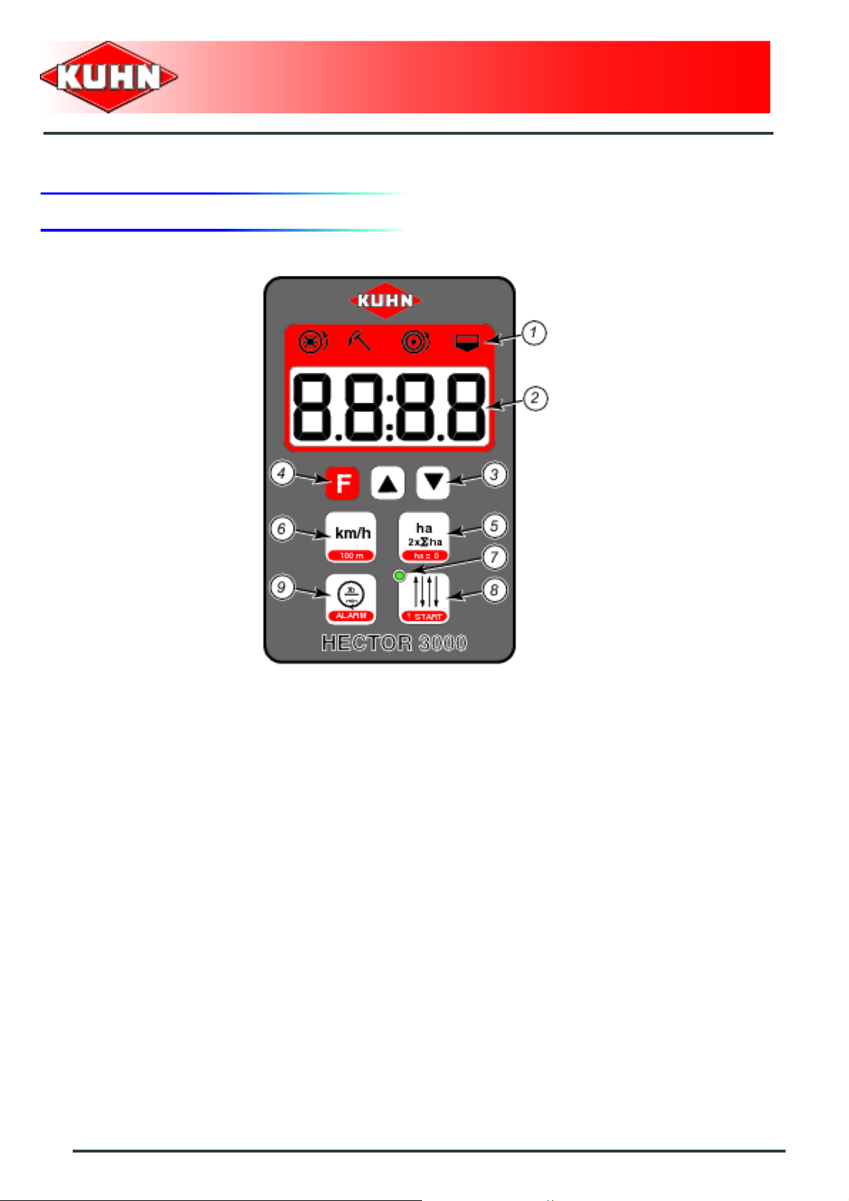
2. Description of the box
INTEGRA G2 \ PREMIA
HECTOR 3000
1 : Symbols 2 : Screen
3 : Data modification keys 4 : Function key
5 : Area button 6 : Speed button / Calibration
7 : Marker display 8 : Marker button
9 : Alarm keys / Blower
10
Specifications
Page 13
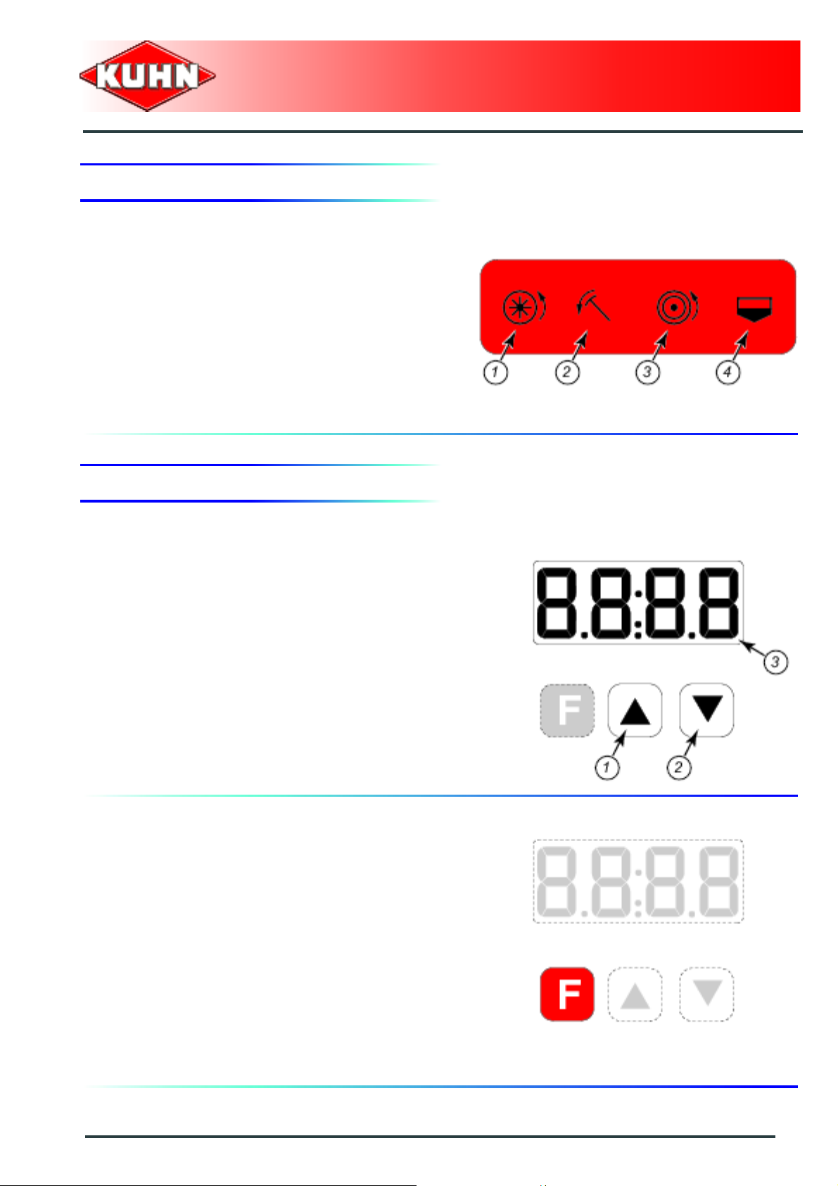
3. Meaning of symbols
Symbol (1):
• Metering units.
Symbol (2):
• Side markers.
Symbol (3):
•Drive wheel.
Symbol (4):
• Seed level.
4. Description of the controls
INTEGRA G2 \ PREMIA
HECTOR 3000
Data modification keys
Keys (1) and (2) enable modifying data displayed on
screen (3).
Function key
- Selecting adjustment parameters.
- Memorizing the adjustments.
Specifications
11
Page 14
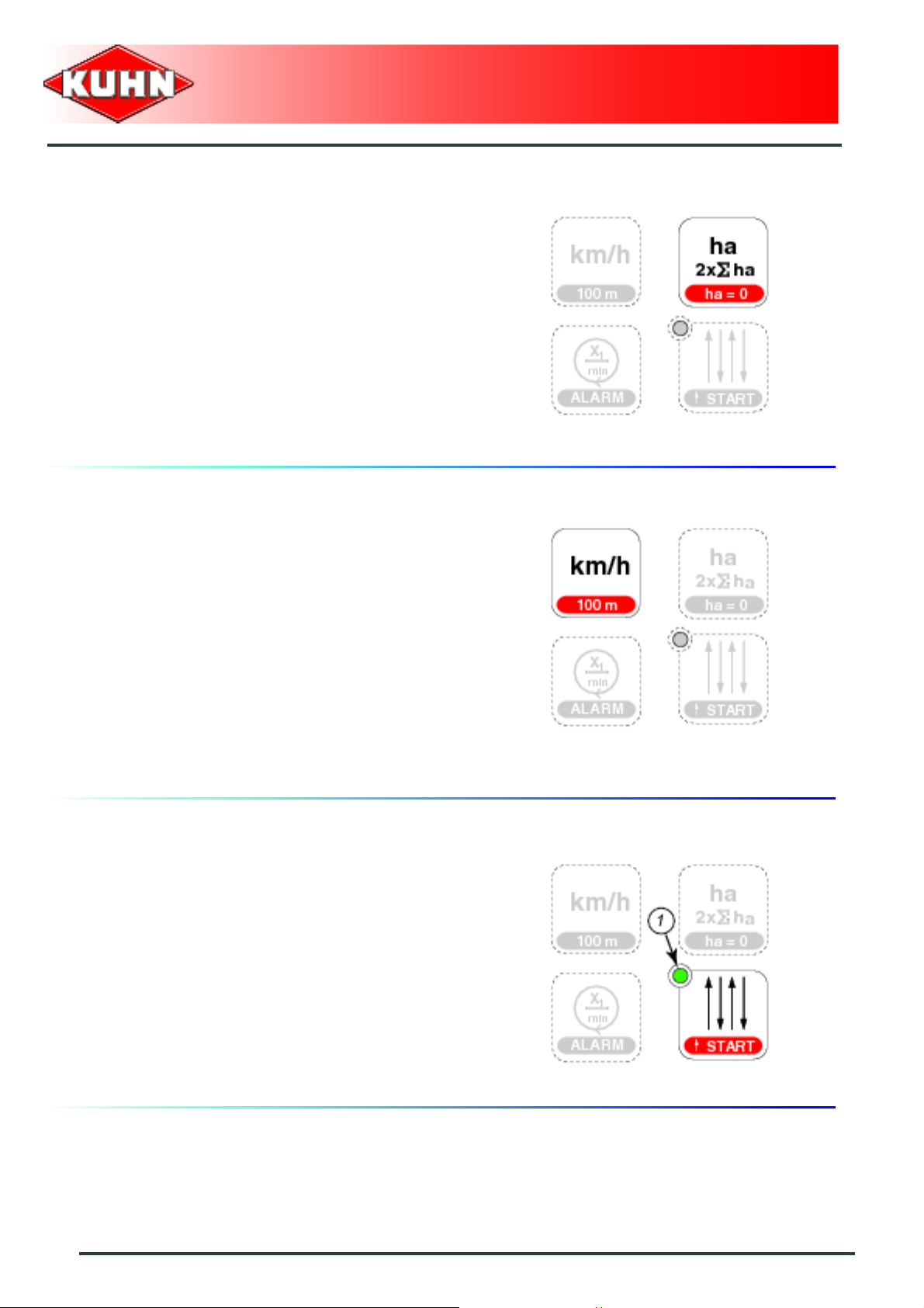
Area button
- Working width adjustment.
- Displaying and adjusting the counters:
• Displaying the daily area counter (ha).
• Displaying the total area counter (ha).
• Counter reset.
Speed button
- Displays the speed.
- Memorization and calibration of the forward travel
impulses.
INTEGRA G2 \ PREMIA
HECTOR 3000
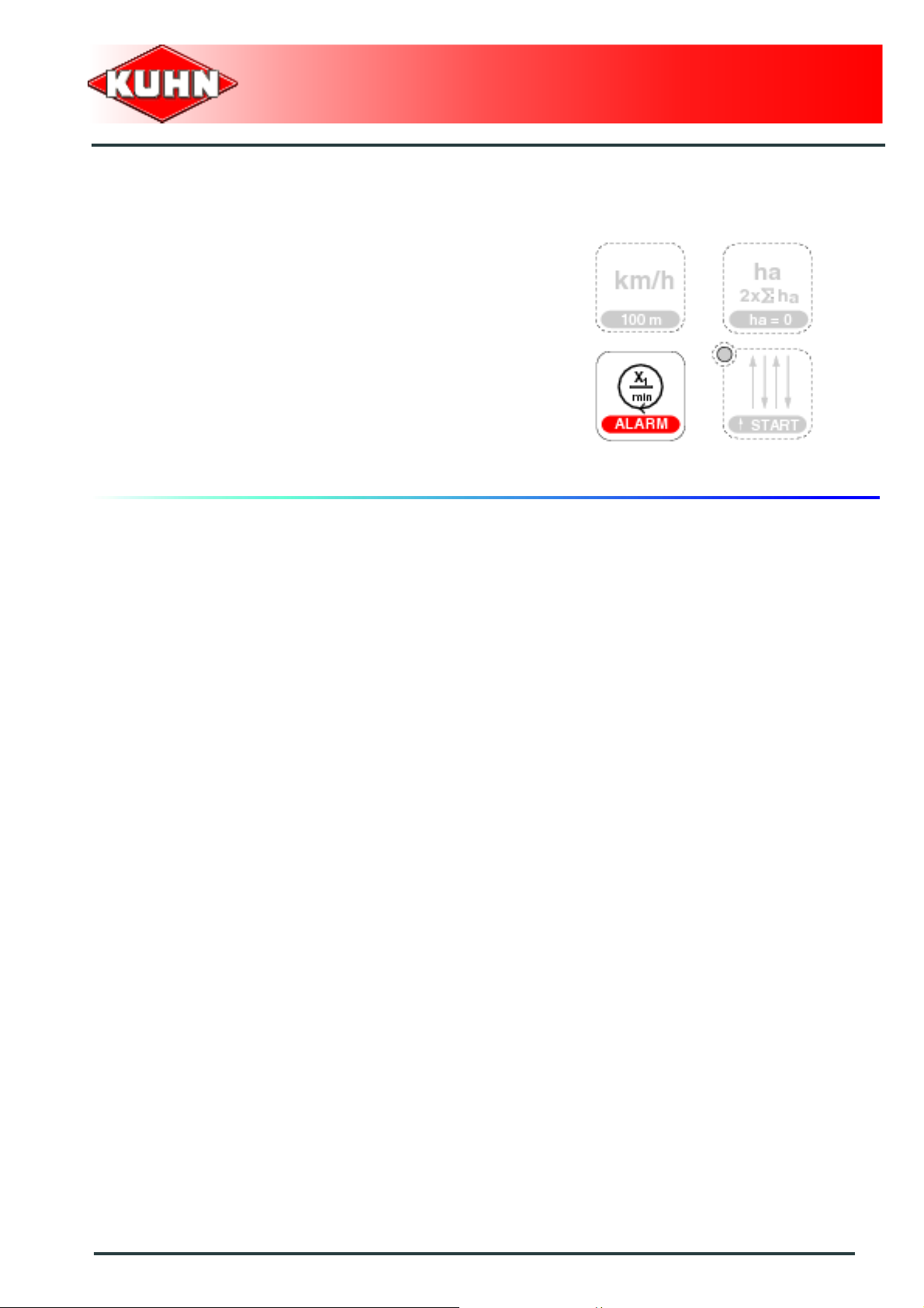
Marker button
- Tramlining metering unit shut-off indicator light (1).
- Displaying the tramlining rhythm.
- Adjusting the tramlining rhythm.
- Tramlining start and stop.
12
Specifications
Page 15
Alarm keys
- Alarm activation and deactivation.
INTEGRA G2 \ PREMIA
HECTOR 3000
Specifications
13
Page 16
$Assembly and fitting
1. Description of the connection
Electrical power supply
Never connect battery charger or perform
welding tasks without having previously
disconnected the control box.
The control box is connected to:
- A tractor 3-pin socket.
- A 7-pin plug of the Hector 3000 junction box.
INTEGRA G2 \ PREMIA
HECTOR 3000
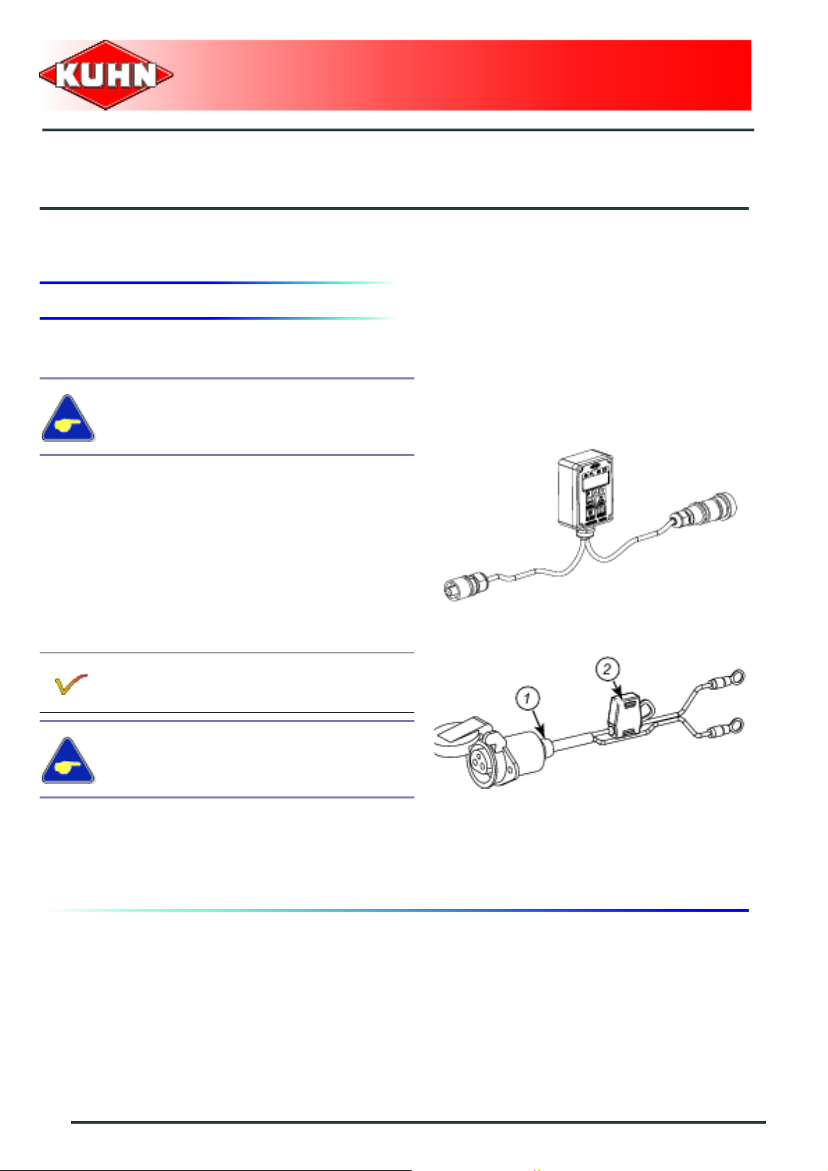
For tractors not fitted with a 3-pin socket, a wiring
harness can be ordered under (1):
Part no. 83233002.
Do not connect the wiring harness to the
starter connections.
Check that the connectors are in a good
condition and clean.
Connect the wiring harness directly to the battery
terminals respecting the polarities.
The wiring harness is fitted with a 15 Amp ATO type
fuse: Kit no. 82333017 (2).
14
Assembly and fitting
Page 17
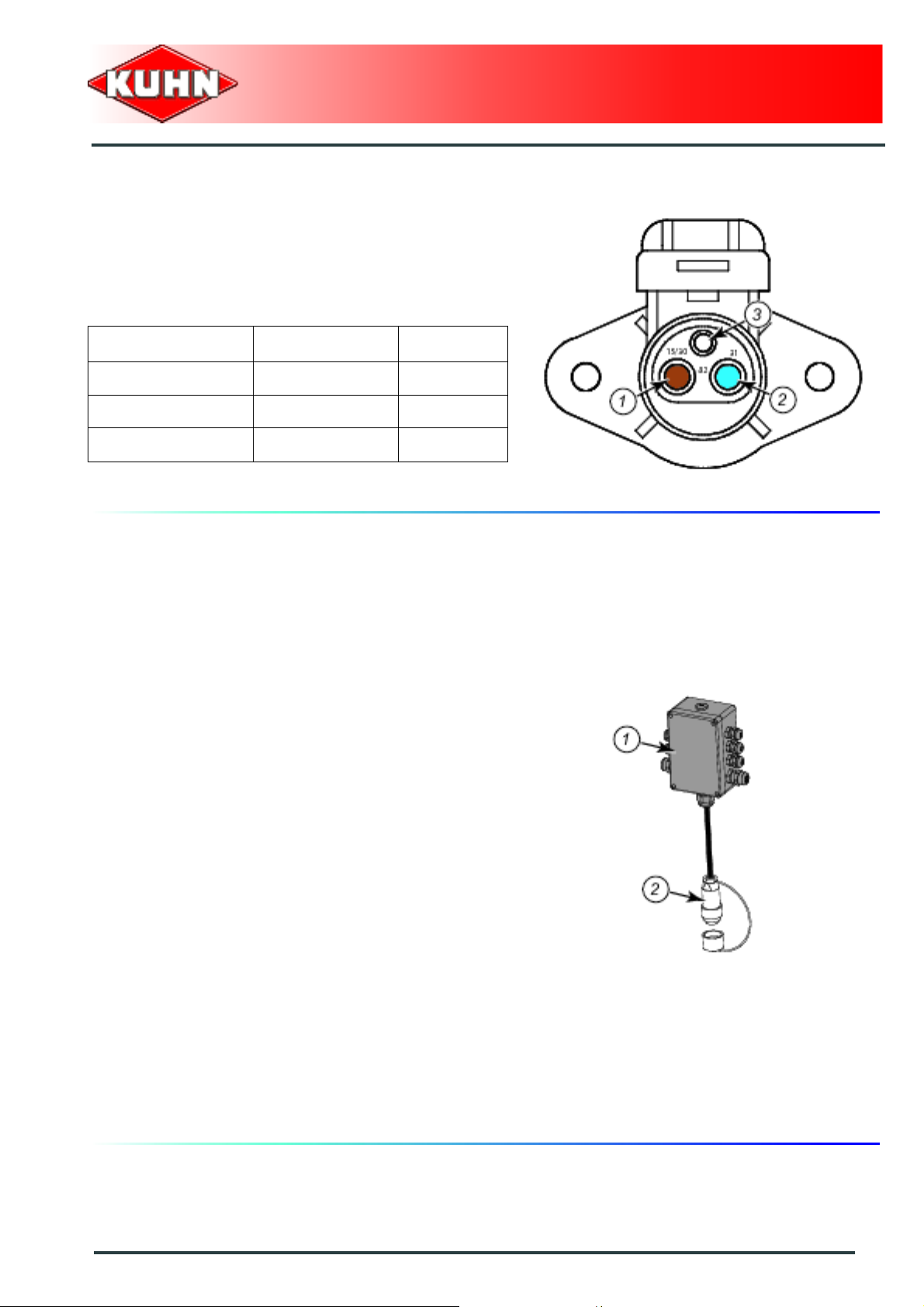
3 pin plug
The box is energized by the tractor's 3-pin socket
(DIN 9680, ISO 12369) or the battery power cable
supplied.
Pin Wire color Function
INTEGRA G2 \ PREMIA
HECTOR 3000
15 / 30 (1)
31 (2)
82 (3)
Junction box
Brown
Blue Ground
+ 12 Volt
--
(INTEGRA G2 from A0001 to C9999):
The Hector 3000 on the seed drill is composed of:
- 1 junction box (1).
- 2 marker sensors.
- 1 tramlining control electro-magnet.
- 1 seed level sensor (Second sensor as optional
equipment on: INTEGRA G2).
- 1 gearbox sensor.
- 2 sensors controlling the metering shaft rotation.
The junction box is connected to the control box with a 7pin plug (2).
(INTEGRA G2 from D0000 to .):
The Hector 3000 on the seed drill is composed of:
- 1 junction box (1).
- 2 marker sensors.
- 1 electric tramlining control cylinder.
- 1 seed level sensor (Second sensor as optional
equipment on: INTEGRA G2).
- 1 gearbox sensor.
- 2 sensors controlling the metering shaft rotation.
The junction box is connected to the control box with a 7pin plug (2).
Assembly and fitting
15
Page 18

Wiring harness (PREMIA)
The Hector 3000 on the seed drill is composed of:
- 1 wiring harness (1).
- 2 marker sensors.
- 1 electric tramlining control cylinder.
- 1 wheel rotation sensor.
The junction box is connected to the control box with a 7pin plug (2).
INTEGRA G2 \ PREMIA
HECTOR 3000
16
Assembly and fitting
Page 19

2. Electrical diagrams
INTEGRA G2 from A0001 to C9999
L = 4.5 m (14’9’’)
INTEGRA G2 \ PREMIA
HECTOR 3000
Side marker sensor (1)
Additional hopper bottom
sensor
Side marker sensor (2)
Metering unit drive shaft 1
L = 0.8 m (2’7’’)
Metering unit drive shaft 2
Hopper base sensor
L = 0.8 m (2’7’’)
L = 0.5 m (1’8’’)
L = 2.6 m (8’6’’)
L = 0.5 m (1’8’’)
L = 0.8 m (2’7’’)
L = 1.5 m (4’11’’)
L = 4.5 m (14’9’’)
Electro-magnet connectors
Gearbox sensor
L = 5 m (16’5’’)
Black
Blue
Brown
Assembly and fitting
17
Jumper for additional hopper bottom sensor
Green - Yellow
White
Red
Green or Grey
Page 20

INTEGRA G2 from D0000 to .....
Side marker sensor
(1)
L = 4.5 m (14’9’’)
L = 0.8 m (2’7’’)
INTEGRA G2 \ PREMIA
HECTOR 3000
Side marker sensor (2)
Metering unit drive shaft 1
L = 4.5 m (14’9’’)
Gearbox sensor
Metering unit drive shaft 2
L = 0.8 m (2’7’’)
L = 0.5 m (1’8’’)
L = 0.8 m (2’7’’)
L = 5 m (16’5’’)
Hopper base sensor
L = 2.6 m (8’6’’)
Electric cylinder connectors
L = 0.5 m (1’8’’)
L = 1.5 m (4’11’’)
Electro-magnet connectors
18
Assembly and fitting
Jumper for additional hopper bottom sensor
White
Green - Yellow
Red
Green or Grey
Blue
Brown
Black
Page 21

PREMIA
INTEGRA G2 \ PREMIA
HECTOR 3000
Speed sensor
Side marker sensor (1)
Electric cylinder connectors
Metering unit drive shaft sensor
Side marker sensor (2)
Pre-emergence
Hopper base sensor
Assembly and fitting
19
Page 22
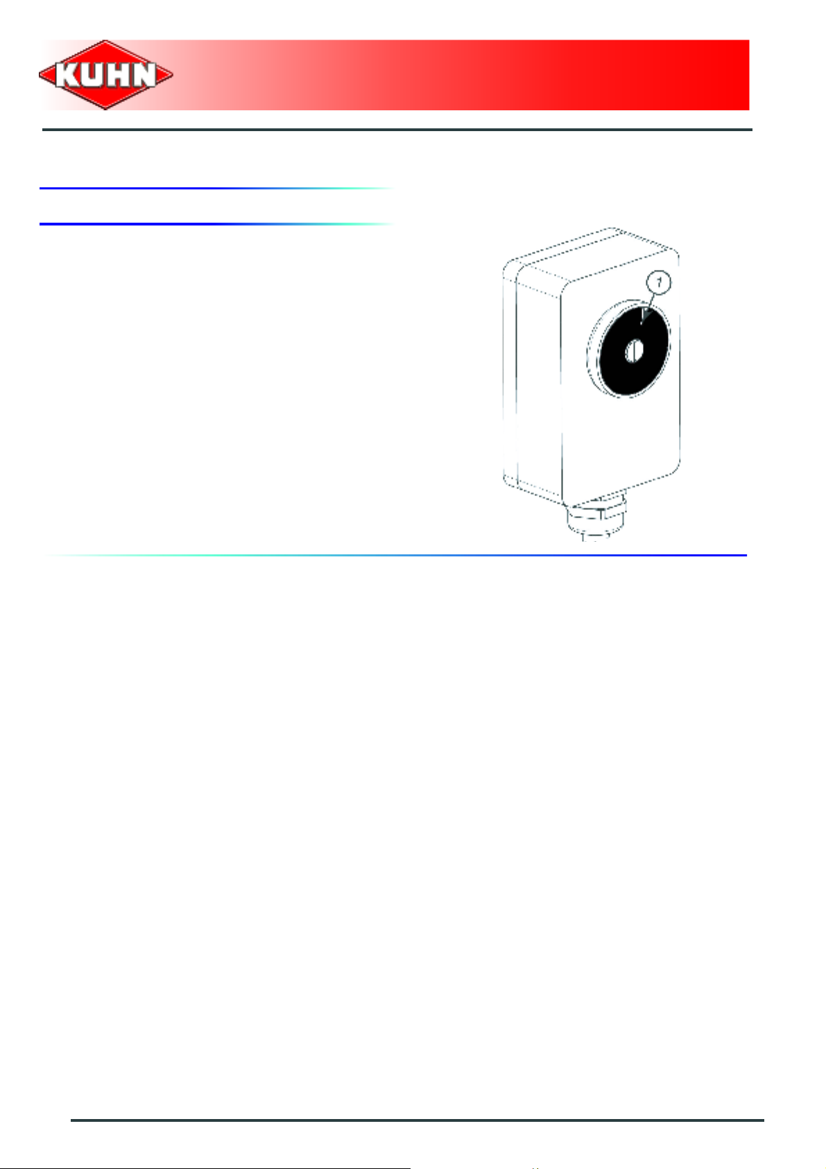
3. Positioning and parking
The control box must be easily accessible from the
tractor cab.
Control box mounting
It is held by means of a magnet (1).
INTEGRA G2 \ PREMIA
HECTOR 3000
Control box removal
Store control box in a dry place free of dust.
20
Assembly and fitting
Page 23

$Putting into service
1. Switches on the control box
Before switching the control box on, check
that nobody is within the machine pivoting
area: switching on the control box can
activate functions on the machine.
Connect control box to the 3-pin electric plug.
INTEGRA G2 \ PREMIA
HECTOR 3000
Putting into service
21
Page 24

$Machine use
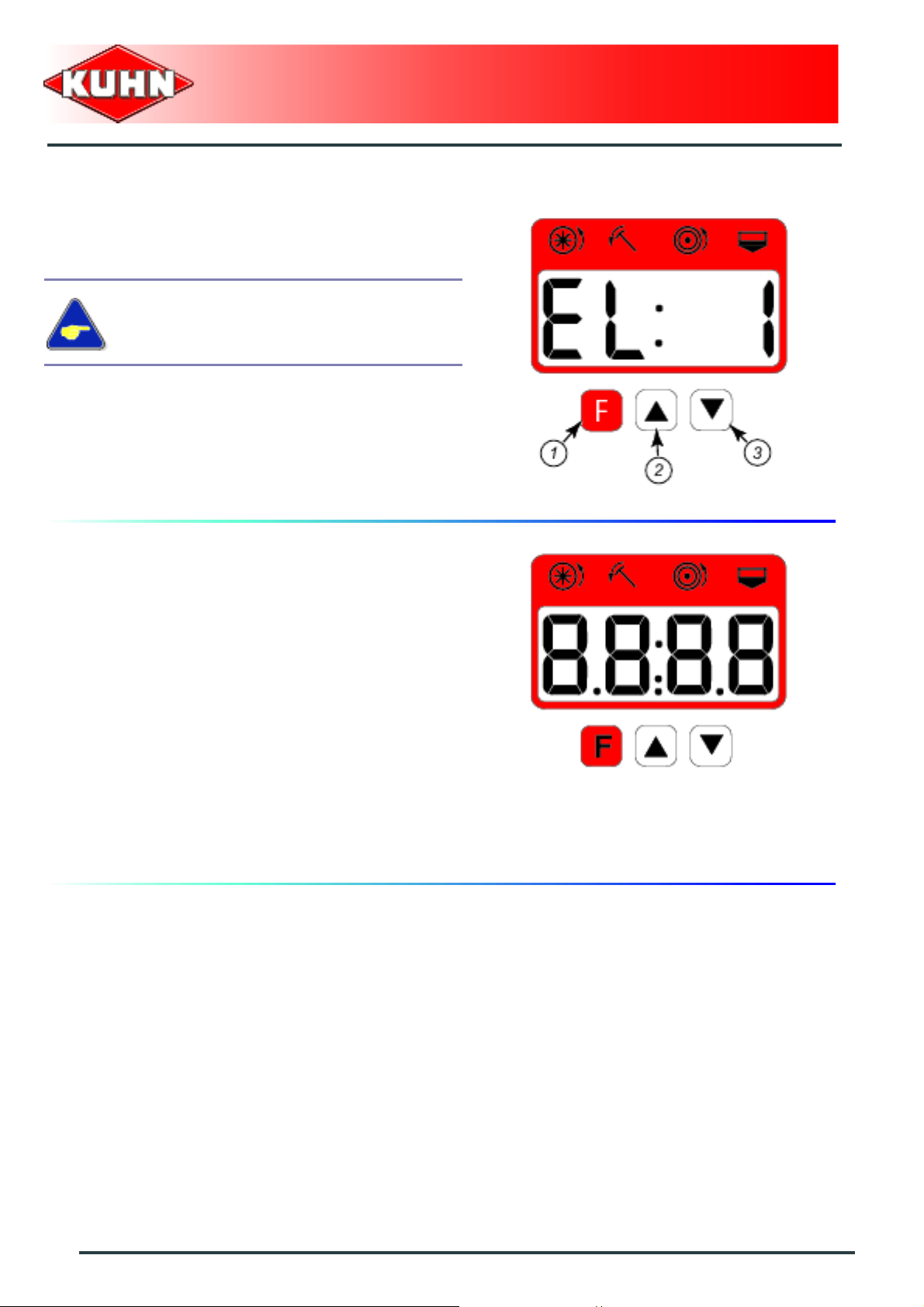
1. Adjustments before first use
Introduction
On switching on the control box press simultaneously
key (1).
- Following parameters can be modified:
• Type of seed drill.
• Number of magnets or tramlining control cylinders.
(Only one on mechanical seed drills).
• Checking the screen.
• Checking sensors.
• Marker sensor signal time delay.
Press key (1) to access the parameters to modify.
INTEGRA G2 \ PREMIA
HECTOR 3000
The adjustable parameter flashes.
- Press keys (2) and (3) to modify the parameters.
Press for approximately 3 seconds on key (1).
- The selection flashes shortly.
The setting is saved.
Press on one of the other keys to leave the configuration
menu.
22
Machine use
Page 25

Configuration of the type of seed drill
The display below the symbols has the following
significations:
Symbols Displays
- t = Pneumatic seed drills.(Blower sensor)
-
-
Side markers:
-
-
Speed sensor:
-
-
INTEGRA G2 \ PREMIA
HECTOR 3000
d = Mechanical seed drills.(Distribution sensor)
E = Precision Seed Drills.
1 = Activated.
0 = Deactivated.
1 = Activated.
0 = Deactivated.
Level sensor:
-
1 = Activated.
-
0 = Deactivated.
- On switching on the control box press simultaneously
key (1).
• The adjustable parameter flashes.
- Press key (3) to modify parameter.
- Press key (2) to access the next parameter.
- Press for approximately 3 seconds on key (1).
• The selection flashes shortly.
- The setting is saved.
- Press key (1) to access the next adjustment.
Configuration for:
INTEGRA G2.
Configuration for:
PREMIA:
- Standard.
- With metering unit sensor as optional
equipment.
Machine use
23
Page 26
Setting the number of electro-magnets or
electric cylinders
Number of magnets or tramlining control cylinders.
- Press keys (3) and (2) to modify the parameter.
Conventional seed drills:
- 1 tramlining control electro-magnet.
- Press for approximately 3 seconds on key (1).
• The selection flashes shortly.
- The setting is saved.
- Press key (1) to access the next adjustment.
INTEGRA G2 \ PREMIA
HECTOR 3000
Checking the screen
Allows checking the screen during 2 seconds, then the
screen passes automatically to the next adjustment.
24
Machine use
Page 27

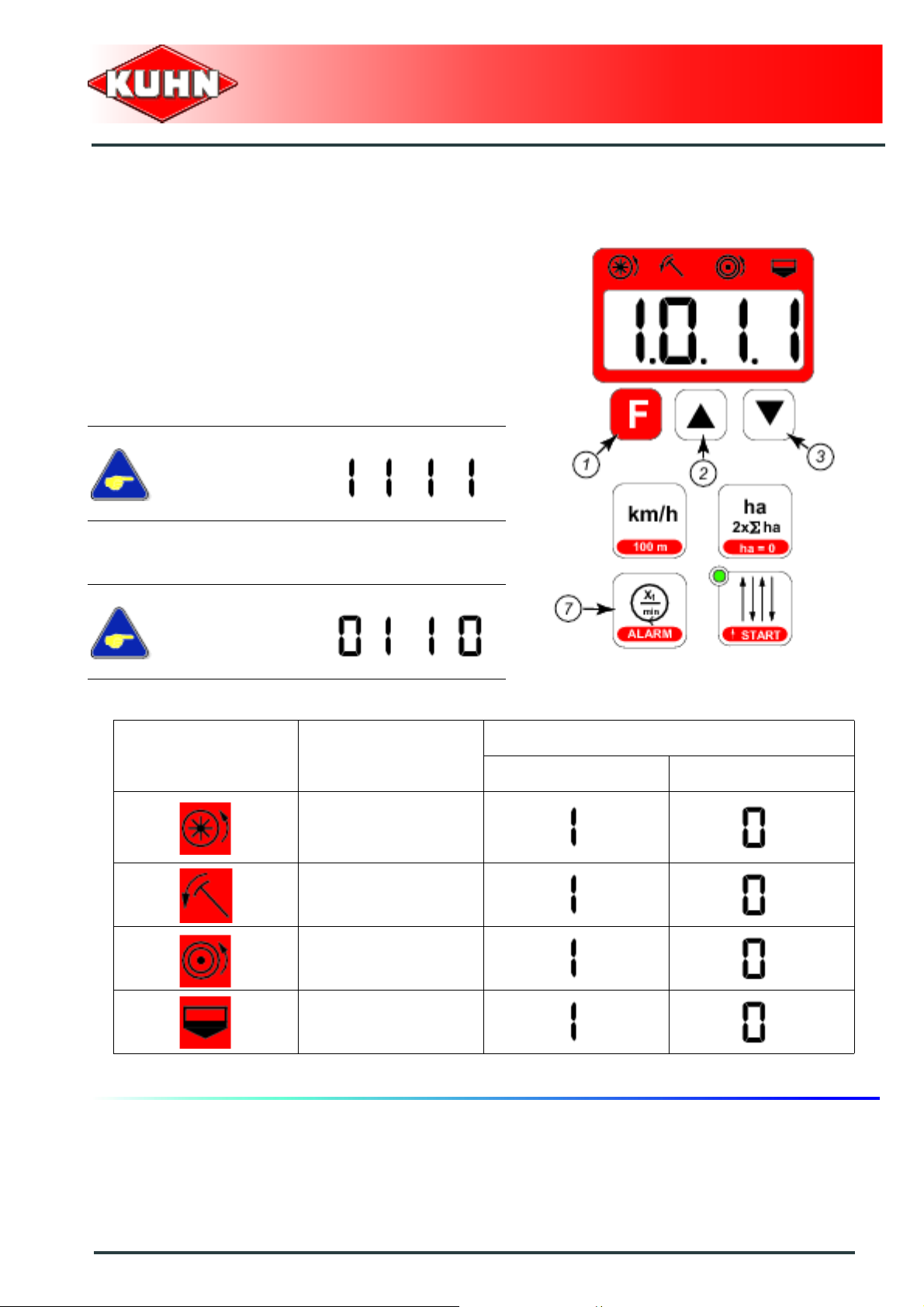
Checking sensors
Allows to check the various seed drill sensors.
- Rotate wheel. (INTEGRA: Gearbox engaged).
• The top segment of the first digit flashes.
- Raise the markers.
• The top segment of the second digit is ON.
- Rotate the distribution drive wheel.
• The top segment of the third digit flashes.
- Cover the hopper sensor.
• The top segment of the fourth digit is ON.
- Press key (1) to access the next adjustment.
INTEGRA G2 \ PREMIA
HECTOR 3000
Machine use
25
Page 28
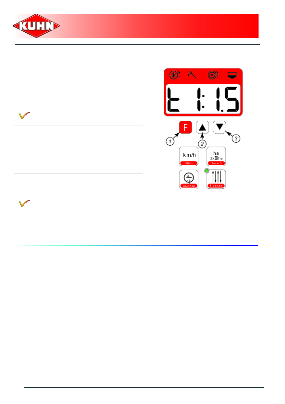
Marker sensor signal time delay
The sensor signal time delay can be adjusted for the
following positions:
-Raised
- Lowered
An increase in the time delay is required for particular
cases where the sensor is not fitted on the marker
The time can be adjusted from 0.0 to 9.9
seconds.
- Press keys (3) and (2) to modify the parameter.
- Press for approximately 3 seconds on key (1).
• The selection flashes shortly.
- The setting is saved.
- Repeat procedure for:
- Press on one of the other keys to leave the
configuration menu.
t 1.
t 2.
t 2.
INTEGRA G2 \ PREMIA
HECTOR 3000
.
Recommended factory setting with markers:
- t1: 0.5 seconds.
- t2: 2.0 seconds.
Recommended factory setting with sensor fitted
on the wheel arm:
- t1: 3.0 seconds.
- t2: 3.0 seconds.
26
Machine use
Page 29

2. Preliminary adjustments at work
Introduction
The following settings which are specific to the mach ine are to be car rie d ou t:
- Working width.
- Memorization and calibration of the forward travel impulses.
- Tramlining rhythm.
- Alarm activation and deactivation.
Working width adjustment
- Press for approximately 3 seconds on key (4).
•Symbol
• The adjustable parameter flashes.
- Press keys (2) and (3) to modify the parameter.
- Press for approximately 3 seconds on key (1).
• The selection flashes shortly.
- The setting is saved.
Lt is displayed during 2 seconds.
INTEGRA G2 \ PREMIA
HECTOR 3000
Press on one of the other keys to leave the
configuration menu.
Machine use
27
Page 30
Memorization and calibration of the
forward travel impulses
In order to display the correct speed and for the hectare
counter to calculate correctly, it is necessary to program
the number of pulses over a distance of 100 m (328’1’’).
There are two possible settings:
- An average value.
- In the field.
In field calibration provides increased accuracy
in the number of impulses.
Setting an average value
- Simultaneously press keys (1) and (5).
•Symbol
- Press keys (2) and (3) to modify the parameter.
• See the adjustment chart.
- Press for approximately 3 seconds on key (1).
• The selection flashes shortly.
- The setting is saved.
InP is displayed during 2 seconds.
INTEGRA G2 \ PREMIA
HECTOR 3000
Press on one of the other keys to leave the
configuration menu.
INTEGRA G2 / PREMIA
Type of seed drill Impulses/100m (328’1’’)
INTEGRA G2 480
PREMIA (Wheels 6.00 x 16) 832
28
Machine use
Page 31

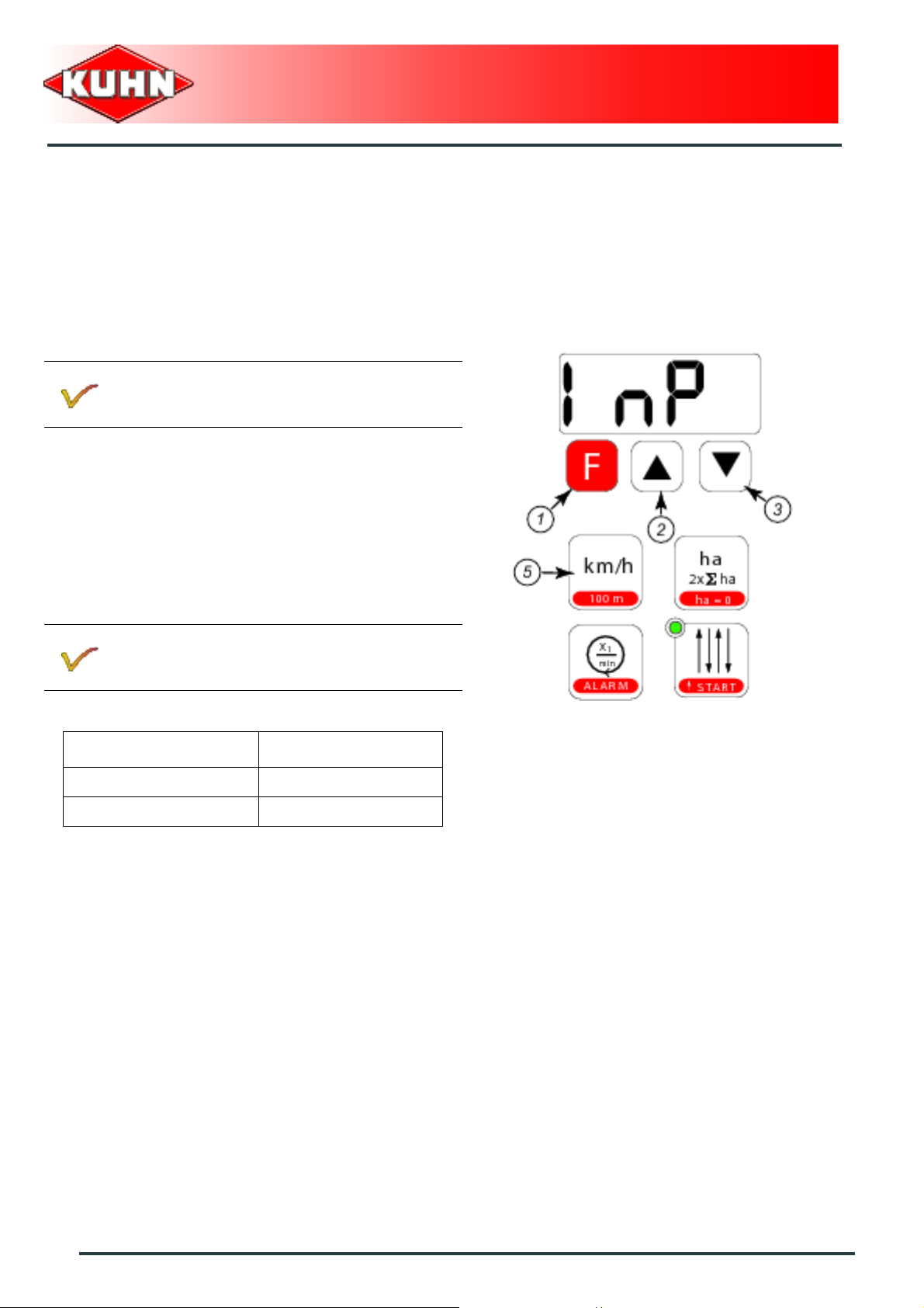
Field calibration
The field calibration is carried out over a
distance of 100m (328’1’’).
- Simultaneously press keys (1) and (5).
•Symbol
• The memorized parameter appears.
- Simultaneously press keys (2) and (3).
•Symbol
The calibration mode is activated.
- Press key (2) to start the counting.
LnP is displayed during 2 seconds.
CAL is displayed during 2 seconds.
Cover a distance of 100m (328’1’’).
INTEGRA G2 \ PREMIA
HECTOR 3000
- Press key (3) to stop the counting.
- Press for approximately 3 seconds on key (1).
• The selection flashes shortly.
- The setting is saved.
Press on one of the other keys to leave the
configuration menu.
Machine use
29
Page 32

Adjusting the tramlining rhythm
Before starting sowing, set the tramlining rhythm.
This rhythm depends on the seed drill widths and the
treatment machine.
- See the adjustment chart.
Adjustment chart
- In symmetrical rhythms SY, the wheel track marking
will be done in a single sowing strip.
Asymmetrical rhythms SY2 SY4 SY6 SY8
SY10 SY12 require to start with a half seed
drill.
INTEGRA G2 \ PREMIA
HECTOR 3000
Asymmetrical rhythms
AS perform the wheel track
marking over two consecutive sowing strips.
- Disconnect the paddle of the disengagement system
on the seed drill side not concerned by tramlining.
Treatment width
Width of
seed drill
2.50 m
(8’2’’)
3.00 m
(9’10’’)
4.00 m
(13’1’’)
Width of
seed drill
2.50 m
(8’2’’)
12.00 m
(39’4’’)
SY4 / AS4 SY5 SY6 / AS6 SY7 SY8 / AS8 SY9
SY3 SY4 / AS4 SY5 SY6 / AS6
28.00 m
(91’10’’)
15.00 m
(49’3’)
SY6 / AS6 SY8 / AS8
30.00 m
(98’5’)
SY12 /
AS12
16.00 m
(52’6’’)
32.00 m
(105’)
18.00 m
(59’1’’)
Treatment width
33.00 m
(108’3’’)
20.00 m
(65’7’’)
36.00 m
(118’1’’)
21.00 m
(68’11’’)
40.00 m
(131’3’’)
24.00 m
(78’9’’)
42.00 m
(137’10’’)
27.00 m
(88’7’’)
48.00 m
(157’6’’)
30
3.00 m
(9’10’’)
4.00 m
(13’1’’)
Machine use
SY10 /
AS10
SY7 SY8 / AS8 SY9
SY11
SY12 /
AS12
SY10 /
AS10
Page 33

Adjustment procedure
- Press for approximately 3 seconds on key (6).
• The stored rhythm flashes.
- Using keys (2) and (3), select the required tramlining
rhythm.
• See the adjustment chart.
- Press for approximately 3 seconds on key (1).
• The selection flashes shortly.
- The setting is saved.
According to the tramlining rhythm chosen, select the
side on which the sowing job is to be started.
- Press on the button (1).
- Select the start side using keys (2) or (3).
- Press for approximately 3 seconds on key (1).
• The selection flashes shortly.
- The setting is saved.
INTEGRA G2 \ PREMIA
HECTOR 3000
Machine use
31
Page 34

Rhythm 3 symmetrical
- 3.00 m (9’10’’) sowing.
- 9.00 m (29’6’’) treatment.
Or
- 4.00 m (13’1’’) sowing.
- 12.00 m (39’4’’) treatment.
Sowing start: Edge on the left or right
Programming:
- Rhythm SY3 (a).
INTEGRA G2 \ PREMIA
HECTOR 3000
Display at start of work:
- Full seed drill (b).
Wheel tracks:
- Rhythm 3 / Position 3 (c).
Rhythm 4 symmetrical
- 3.00 m (9’10’’) sowing.
- 12.00 m (39’4’’) treatment.
Or
- 4.00 m (13’1’’) sowing.
- 16.00 m (52’6 ’’) treatment.
Sowing start: Edge on the left or right
Programming:
- Rhythm SY4 (a).
Display at start of work:
- Half seed drill (b).
Wheel tracks:
- Rhythm 4 / Position 4 (c).
32
Machine use
Page 35

Rhythm 4 asymmetrical
- 3.00 m (9’10’’) sowing.
- 12.00 m (39’4’’) treatment.
Or
- 4.00 m (13’1’’) sowing.
- 16.00 m (52’6’’) treatment.
Sowing start: Edge to the left
Programming:
- Rhythm AS4 (a).
- Start on the left (b).
Display at start of work:
- Start on the left. Position 3 (c).
- Full seed drill (d).
INTEGRA G2 \ PREMIA
HECTOR 3000
Wheel tracks:
- Rhythm 4 / Position 4 (e).
Sowing start: Edge to the right
Programming:
- Rhythm AS4 (a).
- Start on the right (b).
Display at start of work:
- Start on the right. Position 3 (c).
- Full seed drill (d).
Wheel tracks:
- Rhythm 4 / Position 4 (e).
Machine use
33
Page 36

Rhythm 5 symmetrical
- 3.00 m (9’10’’) sowing.
- 15.00 m (49’3’’) treatment.
Or
- 4.00 m (13’1’’) sowing.
- 20.00 m (65’7’’) treatment.
Sowing start: Edge on the left or right
Programming:
- Rhythm SY5 (a).
INTEGRA G2 \ PREMIA
HECTOR 3000
Display at start of work:
- Full seed drill (b).
Wheel tracks:
- Rhythm 5 / Position 5 (c).
Rhythm 6 symmetrical
- 3.00 m (9’10’’) sowing.
- 18.00 m (59’1’’) treatment.
Or
- 4.00 m (13’1’’) sowing.
- 24.00 m (78’9’’) treatment.
Sowing start: Edge on the left or right
Programming:
- Rhythm SY6 (a).
Display at start of work:
- Half seed drill (b).
Wheel tracks:
- Rhythm 6 / Position 6 (c).
34
Machine use
Page 37
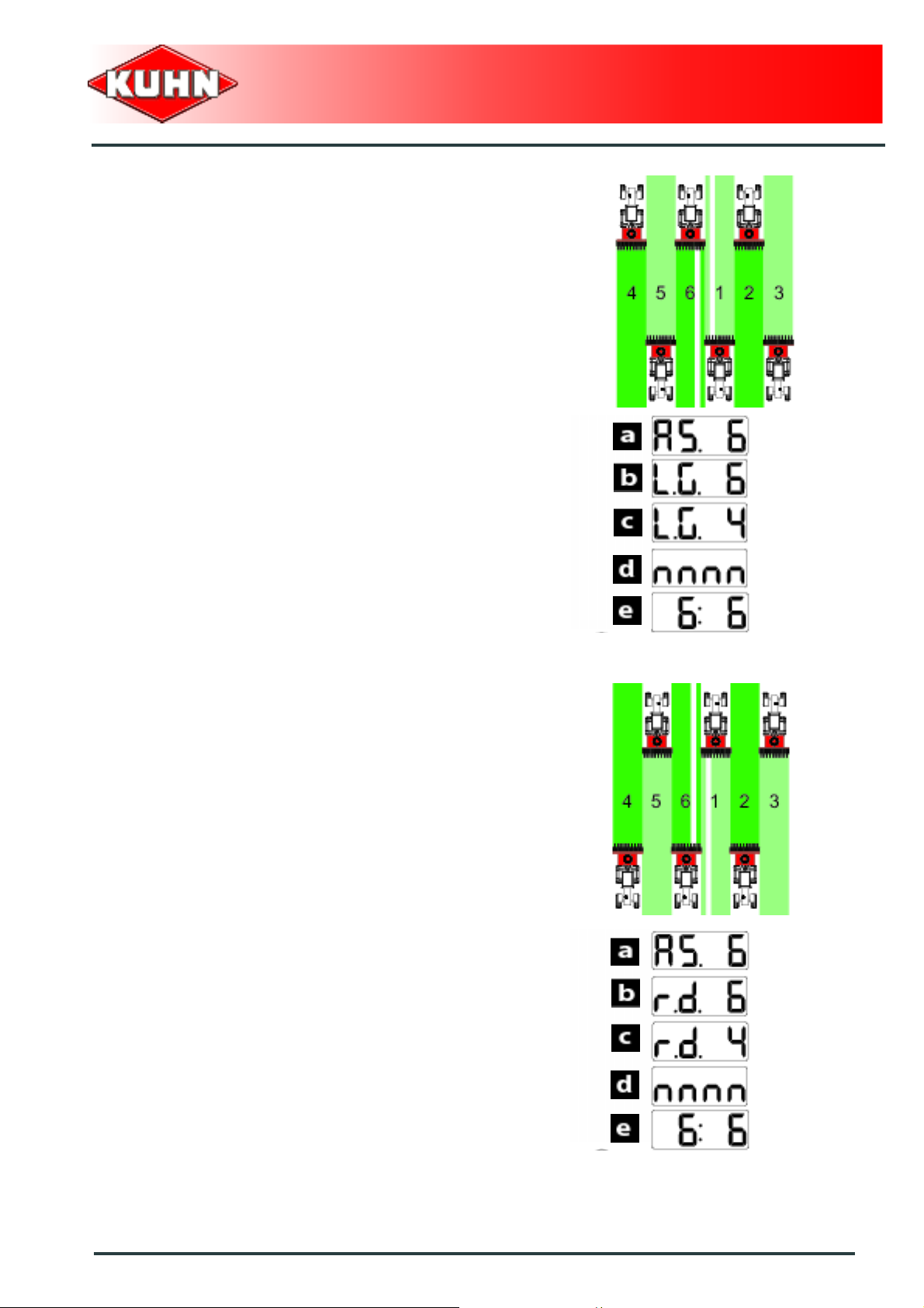
Rhythm 6 asymmetrical
- 3.00 m (9’10’’) sowing.
- 18.00 m (59’1’’) treatment.
Or
- 4.00 m (13’1’’) sowing.
- 24.00 m (78’9’’) treatment.
Sowing start: Edge to the left
Programming:
- Rhythm AS6 (a).
- Start on the left (b).
Display at start of work:
- Start on the left. Position 4 (c).
- Full seed drill (d).
INTEGRA G2 \ PREMIA
HECTOR 3000
Wheel tracks:
- Rhythm 6 / Position 6 (e).
Sowing start: Edge to the right
Programming:
- Rhythm AS4 (a).
- Start on the right (b).
Display at start of work:
- Start on the right. Position 4 (c).
- Full seed drill (d).
Wheel tracks:
- Rhythm 6 / Position 6 (e).
Machine use
35
Page 38

Rhythm 7 symmetrical
- 3.00 m (9’10’’) sowing.
- 21.00 m (68’11’’) treatment.
Or
- 4.00 m (13’1’’) sowing.
- 28.00 m (91’10’’) treatment.
Sowing start: Edge on the left or right
Programming:
- Rhythm SY7 (a).
INTEGRA G2 \ PREMIA
HECTOR 3000
Display at start of work:
- Full seed drill (b).
Wheel tracks:
- Rhythm 7 / Position 7 (c).
Rhythm 8 symmetrical
- 3.00 m (9’10’’) sowing.
- 24.00 m (78’9’’) treatment.
Or
- 4.00 m (13’1’’) sowing.
- 32.00 m (105’) treatment.
Sowing start: Edge on the left or right
Programming:
- Rhythm SY8 (a).
Display at start of work:
- Half seed drill (b).
Wheel tracks:
- Rhythm 8 / Position 8 (c).
36
Machine use
Page 39

Rhythm 8 asymmetrical
- 3.00 m (9’10’’) sowing.
- 24.00 m (78’9’’) treatment.
Or
- 4.00 m (13’1’’) sowing.
- 32.00 m (105’) treatment.
Sowing start: Edge to the left
Programming:
- Rhythm AS8 (a).
- Start on the left (b).
Display at start of work:
- Start on the left. Position 5 (c).
- Full seed drill (d).
INTEGRA G2 \ PREMIA
HECTOR 3000
Wheel tracks:
- Rhythm 8 / Position 8 (e).
Sowing start: Edge to the right
Programming:
- Rhythm AS8 (a).
- Start on the right (b).
Display at start of work:
- Start on the right. Position 5 (c).
- Full seed drill (d).
Wheel tracks:
- Rhythm 8 / Position 8 (e).
Machine use
37
Page 40

Rhythm 9 symmetrical
- 3.00 m (9’10’’) sowing.
- 27.00 m (88’7’’) treatment.
Or
- 4.00 m (13’1’’) sowing.
- 36.00 m (118’1’’) treatment.
Sowing start: Edge on the left or right
Programming:
- Rhythm SY9 (a).
INTEGRA G2 \ PREMIA
HECTOR 3000
Display at start of work:
- Full seed drill (b).
Wheel tracks:
- Rhythm 9 / Position 9 (c).
Rhythm 10 symmetrical
- 3.00 m (9’10’’) sowing.
- 30.00 m (98’5’’) treatment.
Or
- 4.00 m (13’1’’) sowing.
- 40.00 m (131’3’’) treatment.
Sowing start: Edge on the left or right
Programming:
- Rhythm SY10 (a).
Display at start of work:
- Half seed drill (b).
Wheel tracks:
- Rhythm 10 / Position 10 (c).
38
Machine use
Page 41

Rhythm 10 asymmetrical
- 3.00 m (9’10’’) sowing.
- 30.00 m (98’5’’) treatment.
Or
- 4.00 m (13’1’’) sowing.
- 40.00 m (131’3’’) treatment.
Sowing start: Edge to the left
Programming:
- Rhythm AS10 (a).
- Start on the left (b).
Display at start of work:
- Start on the left. Position 6 (c).
- Full seed drill (d).
INTEGRA G2 \ PREMIA
HECTOR 3000
Wheel tracks:
- Rhythm 10 / Position 10 (e).
Sowing start: Edge to the right
Programming:
- Rhythm AS10 (a).
- Start on the right (b).
Display at start of work:
- Start on the right. Position 6 (c).
- Full seed drill (d).
Wheel tracks:
- Rhythm 10 / Position 10 (e).
Machine use
39
Page 42
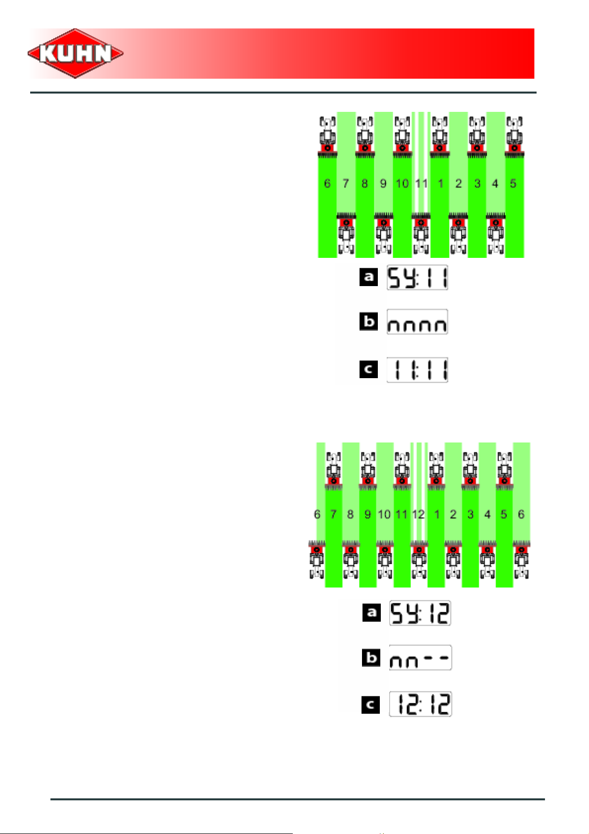
Rhythm 11 symmetrical
- 3.00 m (9’10’’) sowing.
- 33.00 m (108’3’’) treatment.
Or
- 4.00 m (13’1’’) sowing.
- 44.00 m (144’4’’) treatment.
Sowing start: Edge on the left or right
Programming:
- Rhythm SY11 (a).
INTEGRA G2 \ PREMIA
HECTOR 3000
Display at start of work:
- Full seed drill (b).
Wheel tracks:
- Rhythm 11 / Position 11 (c).
Rhythm 12 symmetrical
- 3.00 m (9’10’’) sowing.
- 36.00 m (118’1’’) treatment.
Or
- 4.00 m (13’1’’) sowing.
- 48.00 m (157’6’’) treatment.
Sowing start: Edge on the left or right
Programming:
- Rhythm SY12 (a).
Display at start of work:
- Half seed drill (b).
Wheel tracks:
- Rhythm 12 / Position 12 (c).
40
Machine use
Page 43

Rhythm 12 asymmetrical
- 3.00 m (9’10’’) sowing.
- 36.00 m (118’1’’) treatment.
Or
- 4.00 m (13’1’’) sowing.
- 48.00 m (157’6’’) treatment.
Sowing start: Edge to the left
Programming:
- Rhythm AS12 (a).
- Start on the left (b).
Display at start of work:
- Start on the left. Position 7 (c).
- Full seed drill (d).
INTEGRA G2 \ PREMIA
HECTOR 3000
Wheel tracks:
- Rhythm 12 / Position 12 (e).
Sowing start: Edge to the right
Programming:
- Rhythm AS12 (a).
- Start on the right (b).
Display at start of work:
- Start on the right. Position 7 (c).
- Full seed drill (d).
Wheel tracks:
- Rhythm 17 / Position 17 (e).
Machine use
41
Page 44

Select the rows to disengage according to
the tractor wheel track (INTEGRA G2)
There are 10 disengageable metering units for the
3.00m and 4.00m (9’10’’ - 13’1’’) seed drills, this allows
selecting the number and position of the rows to
disengage.
INTEGRA G2 \ PREMIA
HECTOR 3000
Number of
rows
20 1.35 m (4’5‘‘) / 2.55 m (8’4’’) 0.45 m (1’6‘‘) / 1.55 m (5’1’’)
INTEGRA G2
3.00 m (9’10’’) and
4.00 m (13’1’’)
Select the rows to disengage according to
24 1.38 m (4’6‘‘) / 2.38 m (7’10’’) 0.75 m (2’6‘‘) / 1.62 m (5’4’’)
28 1.35 m (4’5‘‘) / 2.85 m (9’4’’) 1.05 m (3’5‘‘) / 2.55 m (8’4’’)
32 1.63 m (5’4‘‘) / 2.63 m (8’8’’) 1.37 m (4’6‘‘) / 2.37 m (7’9’’)
Minimum/maximum
symmetrical tramlining wheel
the tractor wheel track (PREMIA)
There are 6 disengageable metering units for 2.50 m
(8’2’’) seed drills and 8 disengageable metering units for
3 m (9’10’’) seed drills.
This allows selecting the number and position of the
rows to disengage.
Number of
rows
Minimum/maximum
symmetrical tramlining wheel
track
track
Minimum/maximum
asymmetrical tramlining wheel
track
Minimum/maximum
asymmetrical tramlining wheel
track
42
PREMIA 250 20 1.38 m (4’6‘‘) / 2.38 m (7’10’’) -
20 1.05 m (3’5‘‘) / 1.95 m (8’4’’) 1.05 m (3’5‘‘) / 2.55 m (8’4’’)
PREMIA 300
24 1.38 m (4’6‘‘) / 2.13 m (7’) 0.88 m (2’10‘‘) / 1.63 m (5’4’’)
Machine use
Page 45
Alarm activation and deactivation
Alarms can be activated or deactivated separately.
- Simultaneously press keys (1) and (7).
- Press key (3) to access the next parameter.
• The adjustable parameter flashes.
- Press key (2) to modify parameter.
- Press for approximately 3 seconds on key (1).
• The selection flashes shortly.
- The setting is saved.
Recommended configuration:
-INTEGRA G2.
INTEGRA G2 \ PREMIA
HECTOR 3000
Recommended configuration:
- PREMIA.
Symbols Functions
Distribution
Side markers
Drive wheel
Seed level
Alarms
Activated Deactivated
Machine use
43
Page 46
3. Use during work
Introduction
The following functions are accessible during work :
- Area counter.
- Displays the speed.
- Tramlining start and stop.
- Displaying the tramlining rhythm.
- Blower rotational speed is on display.
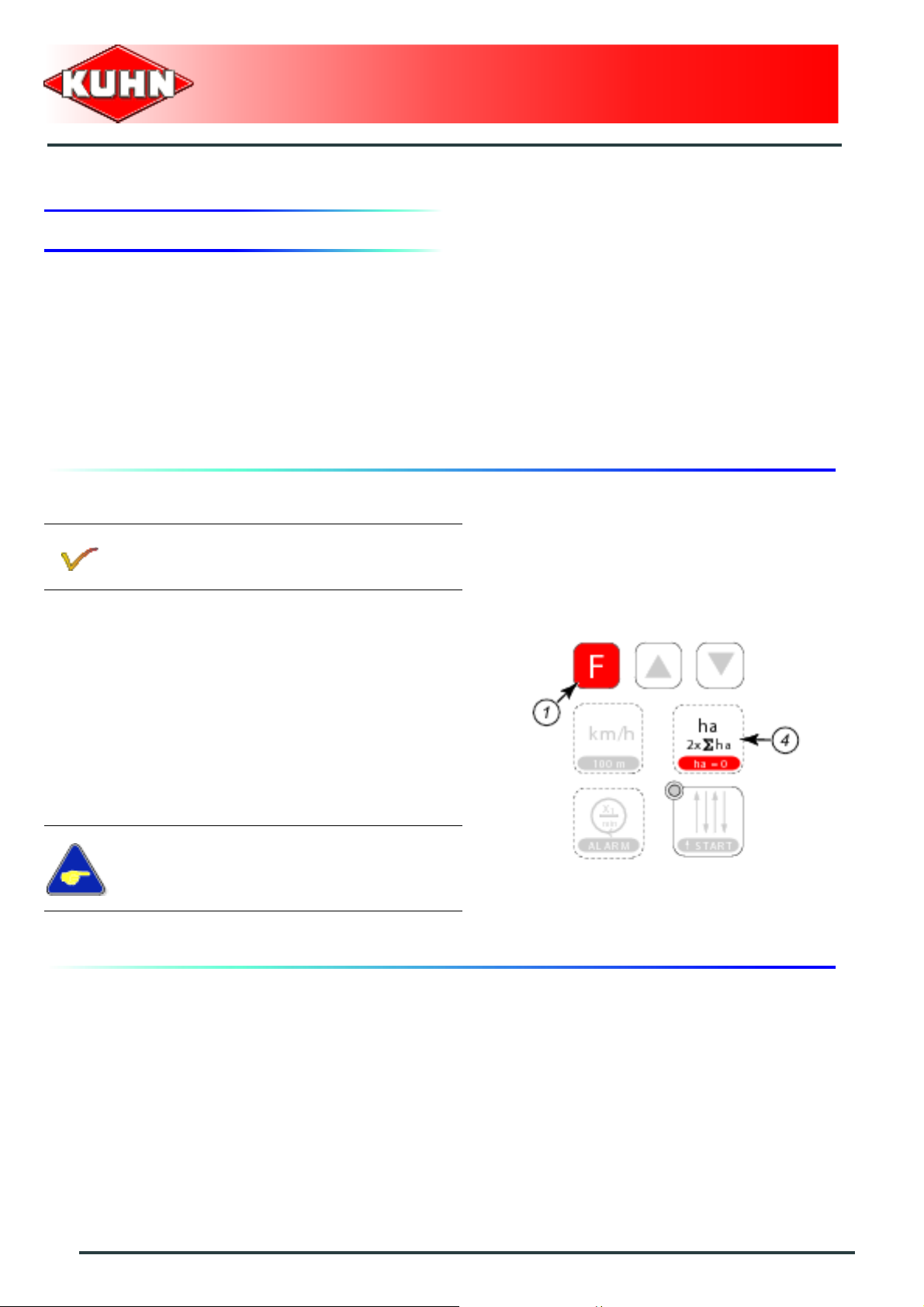
Area counter
INTEGRA G2 \ PREMIA
HECTOR 3000
The counter values remain stored even if the
control box power supply is cut.
Displaying the daily area counter:
- Press 1 time on key (4).
To reset:
- Simultaneously press keys (1) and (4).
Displaying the total area counter:
- Press key (4) a second time.
To reset:
- Simultaneously press keys (1) and (4).
The daily area counter will be reset at the
same time.
44
Machine use
Page 47

Displays the speed
- Press 1 time on key (5).
INTEGRA G2 \ PREMIA
HECTOR 3000
Machine use
45
Page 48

Tramlining start and stop
Tramlining start:
- Press simultaneously keys (1) and (6) to start sowing.
- The screen displays:
• Half seed drill / Full seed drill.
Displaying the tramlining rhythm:
- Press on the button (6).
- The screen displays:
• The tramlining rhythm programmed.
• The position in this tramlining rhythm.
- Press keys (2) or (3) or manipulate markers to scroll
the position counting.
INTEGRA G2 \ PREMIA
HECTOR 3000
Stopping tramlining temporarily:
- Press key (6) to stop the counting.
Pressing key (6) suspends the tramlining rhythm
progress and deactivates keys (2) and (3).
- The screen displays:
- Press key (6) to reactivate the counting.
46
Machine use
StOP.
Page 49

$Simple maintenance
1. Error codes
Alarm messages
Depending on alarm configuration, the following
messages may appear in the event of a fault:
Metering unit rotation
- The metering unit control alarm is displayed if the
shaft does not rotate on the gearbox input side and
the metering unit shaft does not rotate.
INTEGRA G2 \ PREMIA
HECTOR 3000
Side markers
- The alarm is displayed if the wheel has been rotating
for 10 seconds and the marker is not lowered.
Seed drill drive wheels
- The alarm is displayed if one of the markers is lowere d
or the seed drill drive wheel has not been rotating for
10 seconds.
Seed level
- The alarm is activated as soon as the sensor is not
covered with seeds.
The alarm is deactivated when the seed drill is
OFF.
Press following keys to cancel the alarm message
temporarily.
During headland turn maneuvers if the wheel or
the markers are raised, the alarm messages are
inoperative.
- If the minimum seed level alarm message is
interrupted during work, it will come on again every
time that:
• Headland turns are reached: The metering units no
longer rotate.
• The user resumes sowing after having made the
headland turn: Metering units start rotating again.
Simple maintenance
47
Page 50

2. Adjusting the sensors
Gearbox sensor (INTEGRA G2)
The sensor input length (L) inside the gear box must be
of 21 mm (0.9’’).
INTEGRA G2 \ PREMIA
HECTOR 3000
Gearbox sensor (PREMIA)
The distance between the sensor sensitive side and the
gearwheel teeth must be comprised between 1 and 3
mm (0.04’’ - 0.11’’).
Distribution sensor
The distance between the sensor sensitive side and the
metal part must be comprised between 1 and 3 mm
(0.04’’ - 0.11’’).
Distribution sensor (PREMIA)
The distance between the sensor sensitive side and the
metal part must be comprised between 1 and 3 mm
(0.04’’ - 0.11’’).
Marker sensor
The distance between the sensor sensitive side and the
metal part must be comprised between 3 and 5 mm
(0.11’’ - 0.19’’).
48
Simple maintenance
Page 51

$Optional equipment
1. Additional hopper bottom sensor (INTEGRA G2 from A0001 to C9999)
Connect sensor wires to the junction box contacts:
- Brown wire : Pin 5B.
- Black wire: Pin 6B.
- Blue wire: Pin 7B.
INTEGRA G2 \ PREMIA
HECTOR 3000
Remove jumper (1).
2. Additional hopper bottom sensor
(INTEGRA G2 from D0000 to .....)
Connect sensor wires to the junction box contacts:
- Brown wire : Pin +.
- Black wire: Pin F2.
- Blue wire: Pin -.
Remove jumper (1).
Optional equipment
49
Page 52

3. Sensor holder on wheel arm (INTEGRA GII)
Kit no. 1616349
This equipment enables adapting a sensor on the
machine for tramlining with the HECTOR 3000 when the
seed drill is not fitted with side markers.
INTEGRA G2 \ PREMIA
HECTOR 3000
4. Shunt (PREMIA)
Kit no. 83235188
This equipment enables shunting the non-used sensor
signal when side markers are not used.
50
Optional equipment
Page 53

$Maintenance and storage
The control box does not require any particular
maintenance, in the case of a breakdown or a
malfunction call your KUHN technician.
When cleaning the machine, never point the
water jet on the control box or the junction
box.
INTEGRA G2 \ PREMIA
HECTOR 3000
For any welding operation on the machine,
disconnect the electricity supply of the
machine and the tractor (battery and
alternator).
Position the earth as close as possible to the
part to be welded. Never put it on the chassis
to weld on the body or vice-versa. This could
be fatal for the sensors which connect the
body to the chassis.
Washing with a high-pressure cleaner is
strongly advised against, as there is a risk of
water penetrating inside the junction box and
the sensors.
Maintenance and storage
51
Page 54

INTEGRA G2 \ PREMIA
$Limited warranty
HECTOR 3000
52
Limited warranty
Page 55

INTEGRA G2 \ PREMIA
HECTOR 3000
Limited warranty
53
Page 56

 Loading...