

KUHN IND 900, IND 360P, IND 360S Maintenance Manual
1
MAINTENANCE MANUAL
For dealer technicians only
IND 360S STANDARD WEIGHING UNIT
IND 360P PROGRAMMABLE WEIGHING UNIT
Versions 1.1, 1.2 and 1.3
A7310180 4 04-2004
PLEASE READ CAREFULL Y BEFORE TESTING THE MACHINE
IND 900 STANDARD WEIGHING UNIT

2
DEAR OWNER
In buying a KUHN machine you have chosen wisely . Into it have gone years of thought, research and
improvements. You will find, as have thousands of owners all over the world, that you have the best
that engineering skill and actual field testing can produce. You have purchased a dependable machine, but only by proper care and operation can you expect to receive the performance and long
service built into it.
This manual contains all the necessary information for you to receive full efficiency from your machine. The performance you get from this machine is largely dependent upon how well you read and
understand this manual and apply this knowledge. This is a simple machine but in which causes for
trouble are often overlooked even though apparent. These troubles are normally shown in poor work,
though they are largely due to natural wear of parts not being in original adjustment conditions. Therefore,
please DO NOT ASSUME THA T YOU KNOW HOW TO OPERA TE AND MAINT AIN YOUR MACHINE
before reading this manual carefully .
KEEP THIS MANUAL A V AILABLE FOR REFERENCE.
Y our KUHN dealer will instruct you on the general operation of your machine. He wants you to get the
best performance possible and will be glad to answer any special questions that may arise regarding
the operation of the KUHN machine.
Y our KUHN dealer can of fer a complete range of genuine KUHN service p arts.
These parts are manufactured and carefully inspected in the same factory that builds the machine to
assure high quality and accurate fitting of any necessary replacements.
ABOUT IMPROVEMENTS
KUHN is continually striving to improve its products and, therefore, reserves the right to make
improvements or changes when it becomes practical to do so, without incurring any obligations to
make changes or additions to the equipment sold previously .

3
TABLE OF CONTENTS
1 - General ____________________________________________________ 4
1.1 Warning ________________________________________________ 4
1.2 General safety recommendations ____________________________ 5
1.3 Operating conditions ______________________________________ 6
1.3.1 Machines with chassis______________________________ 6
1.3.2 Machines without chassis ___________________________ 7
2 - IND 900 Standard Weighing Unit _______________________________ 9
2.1 Commissioning __________________________________________ 9
2.1.1 Electrical connection _______________________________ 9
2.1.2 Three-sensor machines_____________________________ 9
2.1.3 Four-sensor machines ______________________________ 10
2.2 Weighing unit maintenance _________________________________ 11
2.2.1 Switching on______________________________________ 11
2.2.2 Accessing the maintenance menu_____________________ 12
2.2.3 Description of the maintenance menu functions __________ 12
2.2.4 Testing the sensors ________________________________ 13
2.2.5 Calibrating the unit at two points ______________________ 14
2.2.6 Calibrating the unit at four points ______________________ 17
2.2.7 Auto-Power Off ___________________________________ 20
2.3 Troubleshooting __________________________________________ 21
2.4 Connecting to the junction box _______________________________ 24
3 - IND 360 Standard and Programmable Weighing Unit ______________ 26
3.1 Commissioning __________________________________________ 26
3.2 Weighing unit maintenance _________________________________ 28
3.2.1 Switching on______________________________________ 28
3.2.2 Simple maintenance _______________________________ 29
3.2.3 Specialized maintenance or self-testing_________________ 32
3.3 Troubleshooting __________________________________________ 35
3.4 Connecting to the printed circuit board ________________________ 38
4 - Options ____________________________________________________ 40
4.1 Luminous alarm (on IND 360) _______________________________ 40
4.2 Acoustic alarm (on IND 360) ________________________________ 40
4.3 Internal battery ___________________________________________ 40
4.4. IND 710 remote display ____________________________________ 41
5 - Removing and Refitting the Sensors and the Unit ________________ 42
51 General ________________________________________________ 42
5.2 Machines with chassis_____________________________________ 42
5.2.1 Removing and refitting the Ø 54 sensor_________________ 42
5.2.2 Removing and refitting the Ø 40 sensor_________________ 43
5.3 Machines without chassis __________________________________ 45
5.3.1 Removing the sensor_______________________________ 45
5.3.2 Refitting the sensor ________________________________ 46
5.4 Weighing unit ____________________________________________ 47
5.4.1 Removing and refitting the IND 900 unit _________________ 47
5.4.2 Removing and refitting the IND 360 unit _________________ 48
6 - Maintenance ________________________________________________ 49
7 - Limited Warranty ____________________________________________ 51

4
This symbol is used throughout this manual wherever recommendations
are made concerning the safety of others, or good machine operation.
These recommendations must be made known to all machine operators.
PROPER USE OF THE MACHINE
The weighing unit must only be used for work for which it has been designed:
- Indication of the weight contained in the machine with, for the programmable version, the
possibility of programming animal rations.
The weighing unit must not be used for commercial transactions.
Proper use of the machine also means:
- following operation, maintenance and repair recommendations given by the manufacturer,
- using only spare parts, equipment and accessories as designated by the manufacturer.
The weighing unit must only be used, maintained and repaired by competent persons who are familiar
with the machine specifications and are aware of any danger involved.
The operator must observe current legislation concerning:
- accident prevention
- work safety
1. GENERAL
1.1 WARNING

5
1.2 GENERAL SAFETY RECOMMANDATIONS
Before operating the machine, always ensure that the machine complies with work safety regulations.
GENERAL
1. Safety decals with recommendations to prevent accidents are placed on the machine.
2. Before carrying out work, ensure that the weighing unit is turned off.
3. Portable telephones can have a harmful effect on the working of the weighing unit.
USE
Before connecting the weighing unit to the tractor:
- check that the electric plug is clean and free from dirt,
- check that the electric circuit is correct.
MAINTENANCE
1. Disconnect from the power source before any work is done on the electrical system.
Before any electric welding is carried out on a machine that is attached
to the tractor, disconnect the tractor alternator and battery. Connect
the earth lead as close as possible to the part to be welded. Never
connect the earth to the chassis if the hopper is to be welded. If this
advice is ignored, then irreparable damage can be caused to the sensors
which connect the hopper and chassis.

6
1.3 OPERATING CONDITIONS
1.3.1 MACHINES WITH CHASSIS
Type of machine: EUROMIX I, II and III, all models
AL TOR 9050 and 11050
TURBOMEL 7050, 9050 and 1 1050
Before responding to the message ‘Is the machine empty?’ (IND360) or “--0--” (IND900), ensure
that:
- The tractor engine is switched off.
- The machine is horizontal lengthways and widthways at the transport height; if not, refer to the
section on technical characteristics and tow bar adjustment in the user instructions.
- The machine is not exposed to strong wind.
- The transmission slides effortlessly.
- The chassis is well isolated from the body (check for stray product or foreign bodies).
- The machine’s components (arm, grab and tailgate) are in the idle position (see user instructions).

7
1.3.2 MACHINES WITHOUT CHASSIS
Type of machine: ALTOR 4560, 6070, 7560 and 8060
A THENOR 6070, 7560 and 8060
ALTOR and ATHENOR 4560, 6070 & 7560
Before responding to the message ‘Is the machine empty?’ (IND360) or “--0--” (IND900), ensure
that:
- The tractor engine is switched off.
- The machine is horizontal lengthways and widthways at the transport height; if not, refer to the
section on technical characteristics and tow bar adjustment in the user instructions.
- The machine is not exposed to strong wind.
- The transmission slides effortlessly.
- The machine’s components (arm, grab and tailgate) are in the idle position (see user instructions).
- The brakes are off (parking and service brake) (see user instructions).
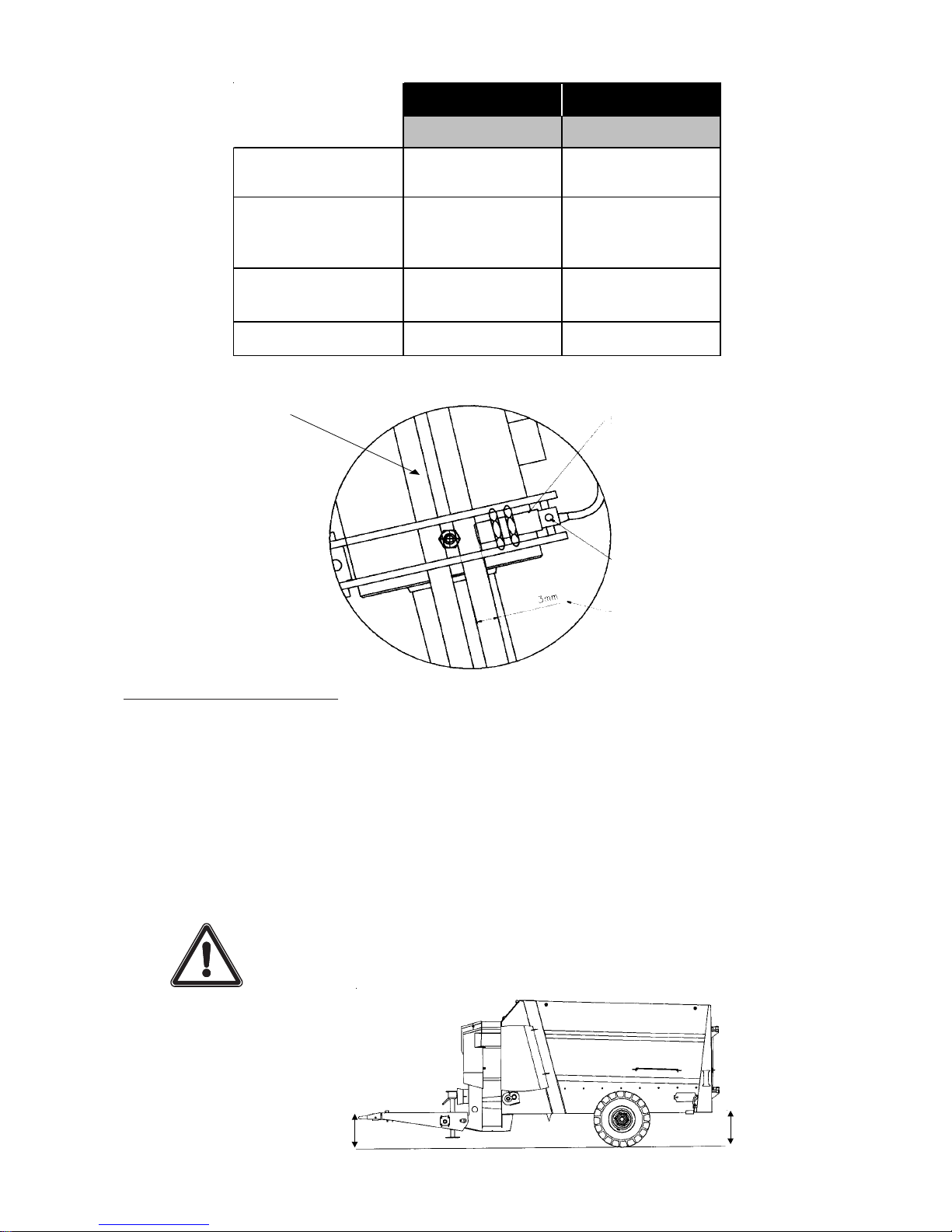
Sufficient clearance is required between the brake shoes and the drum;
any rubbing may cause incorrect weighing.
Adjusting the levelling sensor
- Set the body to height B from the ground and the towing eye bolt to height A, adjust the screw (1) to
position it opposite the sensor, then set the detection distance to approximately 3 mm (maximum
4 mm). The sensor indicator should then light up.
- Tighten the screw and the sensor onto their respective mountings.
- Check the body height setting. T o do this, lower the body to the ground, then raise it until the indicator
lights up and measure the body height. This must be equal to height B ± 10 mm.
If the measured distance is not correct, repeat the adjustment operation.
8
1
Inductive sensor
Indicator lamp
Detection distance
TOWBAR SILL
AB
4560
Short towbar
240 641
4560
Long towbar
(Position B2) *
272 641
6070
(Position B2) *
390 449
7560 332 545
* Refer to the user instructions for the machine.
355 mm
beneath
towing eye
512 mm
beneath body
Towbar setting: position B2
(refer to the user instructions for the machine)
ALTOR AND ATHENOR 8060
Before responding to the message ‘Is the machine empty?’ (IND360) or “--0--” (IND900), ensure
that:
- The tractor engine is switched off.
- The machine is horizontal lengthways and widthways at the transport height (see diagram); if not,
refer to the section on technical characteristics and tow bar adjustment in the user instructions.
- The machine is not exposed to strong wind.
- The transmission slides effortlessly.
- The machine’s components (arm, grab and tailgate) are in the idle position (see user instructions).
- The brakes are off (parking and service brake).
Sufficient clearance is required between the brake shoes and the drum;
any rubbing may cause incorrect weighing.
9
2. IND 900 STANDARD WEIGHING UNIT
2.1 COMMISSIONING
Power supply 12 V (max. 17 V)
Protection against polarity reversal.
- Connect the power cable (A) to the + and - terminals of the tractor battery (beware not to reverse
polarity) and attach the socket to the rear of the tractor cab.
- Connect the unit to the power cable (A).
Before using the weighing unit in cold weather, leave it to warm up for at least ten minutes for a more
stable display .
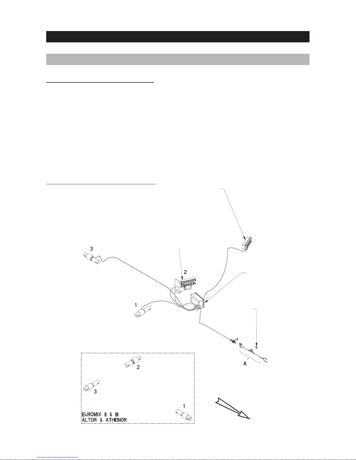
2.1.1 ELECTRICAL CONNECTION
Secondary display
3 sensors
Euromix I
Main indicator
Junction box
Fuse 15A
Ref. 83233017
Front
2.1.2 THREE-SENSOR MACHINES
10
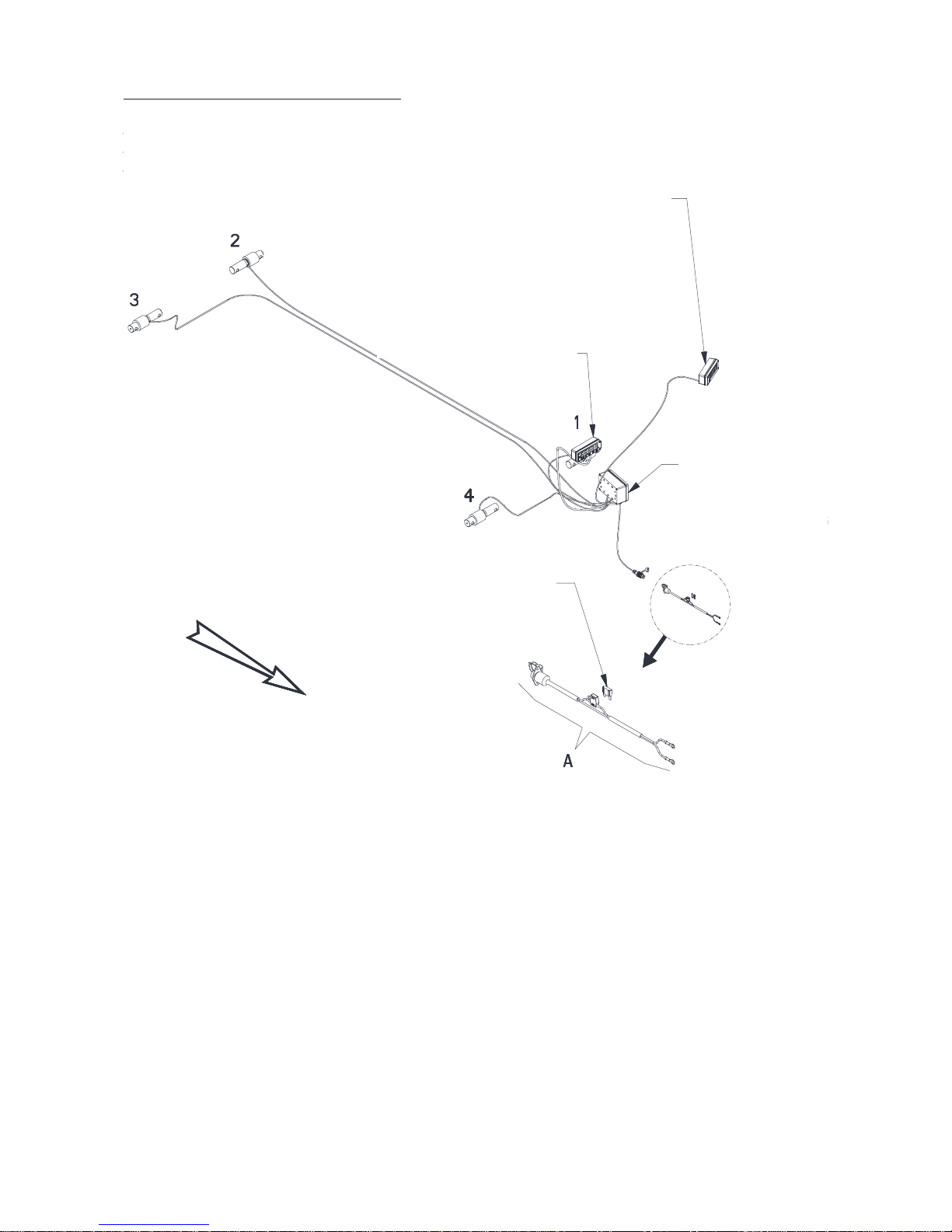
2.1.3 FOUR-SENSOR MACHINES
4 sensors
Euromix I
Euromix III 1050F - 1250F
Secondary display
Main indicator
Junction box
Fuse 15A
Ref. 83233017
Front

11
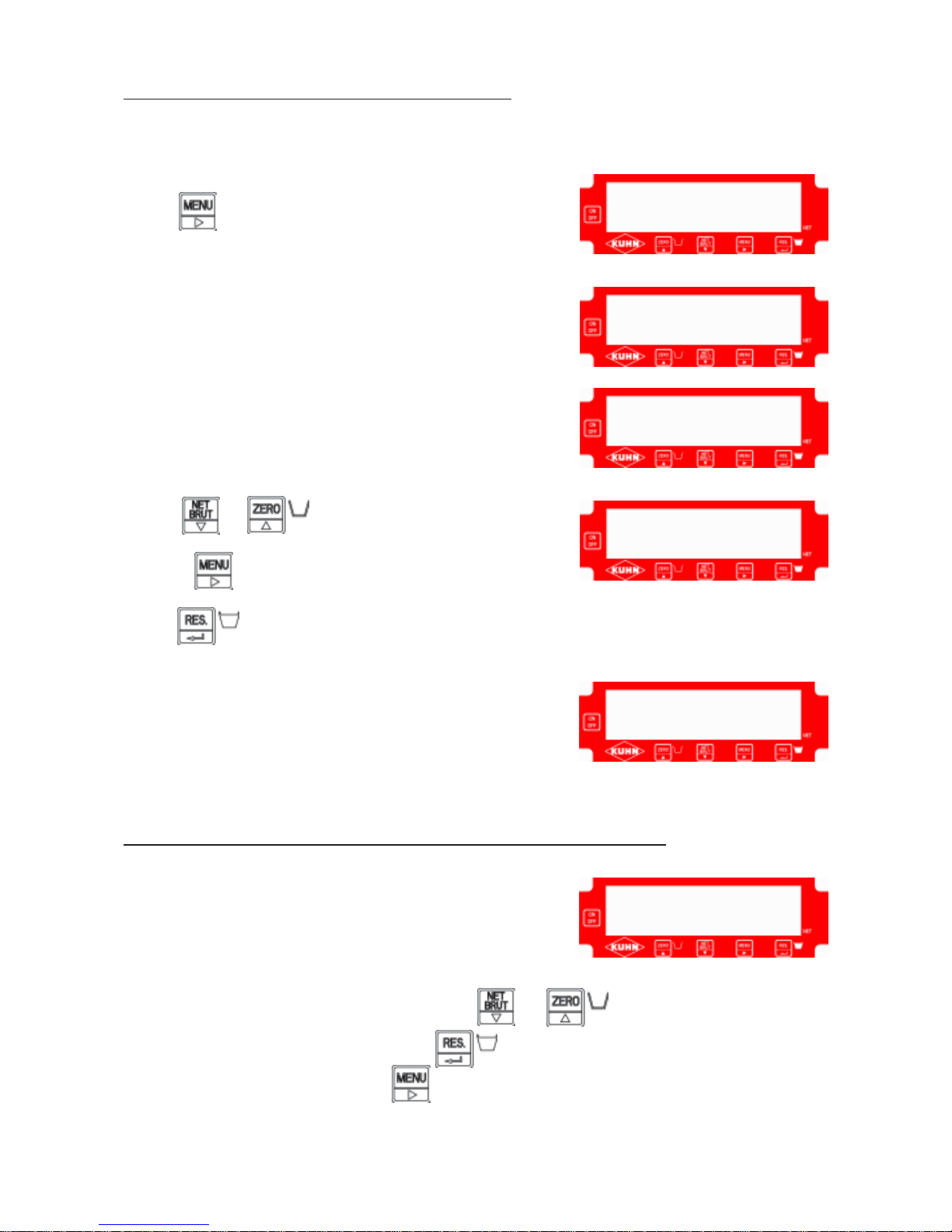
1 - Switch on the unit by pressing
2 - The message “- - - - -” is displayed for ten seconds.
3 - The message “
- - 0 - - “ flashes.
2.2 WEIGHING UNIT MAINTENANCE
- - - - -
2.2.1 SWITCHING ON
- - 0 - -
12
Press
The message “
CodE” is displayed.
The message “
0.000” is displayed. Now enter the main-
tenance code “
5657”.
- Press or to decrease or increase a digit.
- Press to move onto the next digit.
Press to validate.
The message “
F1” is displayed.
F1: Choice between kilograms “
SI” or pounds “Lb”
F2: T wo-point calibration with a standard weight
F3: Sensor voltage test and display
F4: Four-point calibration with factory values
F5: Time-out setting (ON or OFF)
To select a function (F1, F2, F3, F4 or F5), press or
To enter or exit the selected function, press
To exit the maintenance menu, press (when
F1, F2, F3, F4 or F5 is displayed).
Switch on the unit.
- - 0 - C o d E
F 1
F 1
2.2.2 ACCESSING THE MAINTENANCE MENU
2.2.3 DESCRIPTION OF THE MAINTENANCE MENU FUNCTIONS
0.0 0 0
5 6 5 7.
13
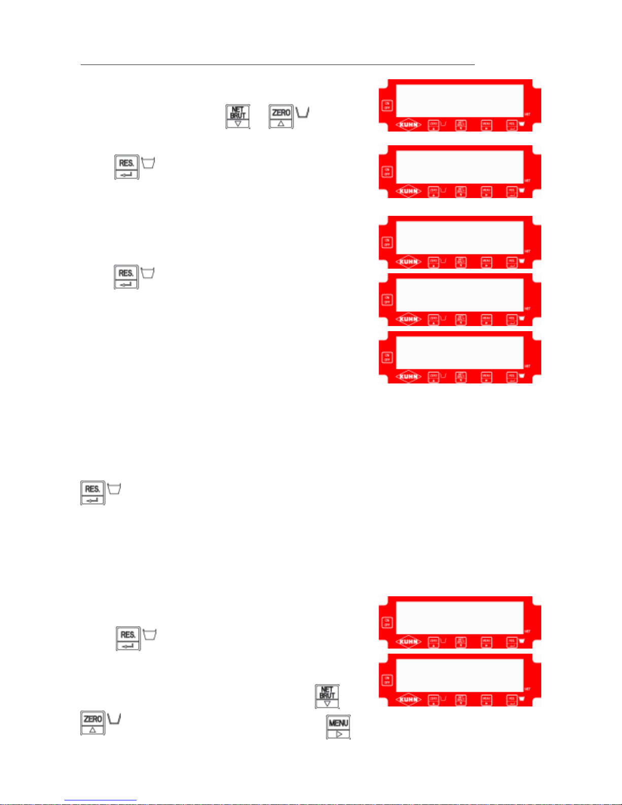
Enter the maintenance menu (see
2.2.2).
Select function F3 by pressing or
Disconnect the sensors in the junction box
Press to validate.
The message “
CELLS” is displayed indicating a sensor fault.
Press
The message “
CELL” is displayed briefly then the message
“
BAD” appears.
Reconnect the first sensor and wait two seconds. If the message “
Good” is displayed, no fault is
detected. If the message “
bad” continues to be displayed, the sensor is faulty (see the section on
connection, broken wire or faulty sensor problems).
Disconnect the first sensor, connect the second and wait for the “
Good” or “bad” diagnosis.
Repeat for each sensor. When the message “
Good” is displayed for the final sensor, press
The sensor voltage is displayed “
X.XXX” (in V).
Note the voltage on the test sheet.
Connect each sensor again one by one to display the
corresponding voltage.
Reconnect all sensors.
The total voltage is displayed “
X.XXX”.
Press to exit function F3.
The message “
F1” is displayed.
You can now choose another function by pressing or
or exit the maintenance menu by pressing
- - - - -
F 3
C E L L S
C E L L
B A D
F 1
2.2.4 TESTING THE SENSORS AND SENSOR VOLTAGE DISPLAYS “F3”
X.X X X
14
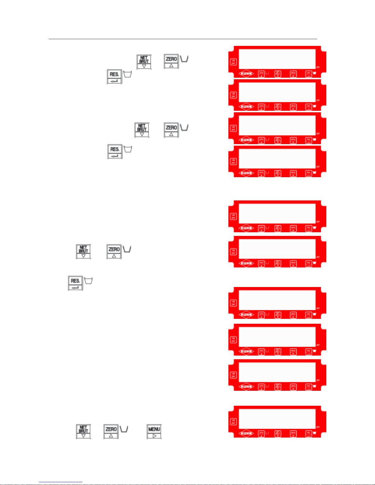
Enter the maintenance menu.
Select function F2 by pressing or
V alidate by pressing
The message “
CALIB” appears briefly.
Select the unit of weight - “
SI” for kilograms or
“
LB” for pounds - by pressing or
V alidate by pressing
The message “
CAL 1” is displayed for one second.
A value “
0” is displayed. If this value differs, reset to zero by
pressing or
Check that nothing is resting on the machine.
Press
The message “
AC0 1” is displayed and a dot scrolls across
the bottom of the screen.
(The weighing unit is calculating measurement 1. This
operation takes around 30 seconds).
The message “
CAL 2” is displayed for one second.
A value “
X.XXX” is displayed.
Display the value of the standard weight (e.g. 2327) by
pressing or and
F2
S I
C A L 1
0.
A C O 1
C A L I B
L b
2.2.5 CALIBRA TING THE UNIT AT TWO POINTS WITH A STANDARD WEIGHT “F2”
X.X X X
2 3 2 7.
C A L 2

15
The message “
AC0 2” is displayed.
Measurement 2 is displayed “
XXXXX”.
Press
Lay the standard weight on the machine.
Press
The message “
AC0 2” is displayed and a dot scrolls across
the bottom of the screen.
(The weighing unit is calculating measurement 2. This
operation takes around 30 seconds).
The message “
CAL 1” is displayed.
V alue 1 displays “
0” intermittently .
Press
The message “
AC0 1” is displayed.
Measurement 1 is displayed “
XXXXX”.
Press
The message “
CAL 2” is displayed.
Value 2 is displayed “
XXXXX” (2327 for the factory standard
weight, for example).
Press
0
A C O 2
C A L 1
A C O 1
X X X X X
C A L 2
2 3 2 7
X X X X X
A C O 2

16
The message “
F1” is displayed.
Press to exit the maintenance menu.
The message “
- - 0 - -” flashes.
If the weight is still on the machine, press
If the weight is no longer on the machine, press
The weighing unit has left maintenance mode and is running normally.
To check that the unit is in good working order:
- carry out successive measurements of the standard weight
- reset to zero.
- - 0 - -
F 1
17
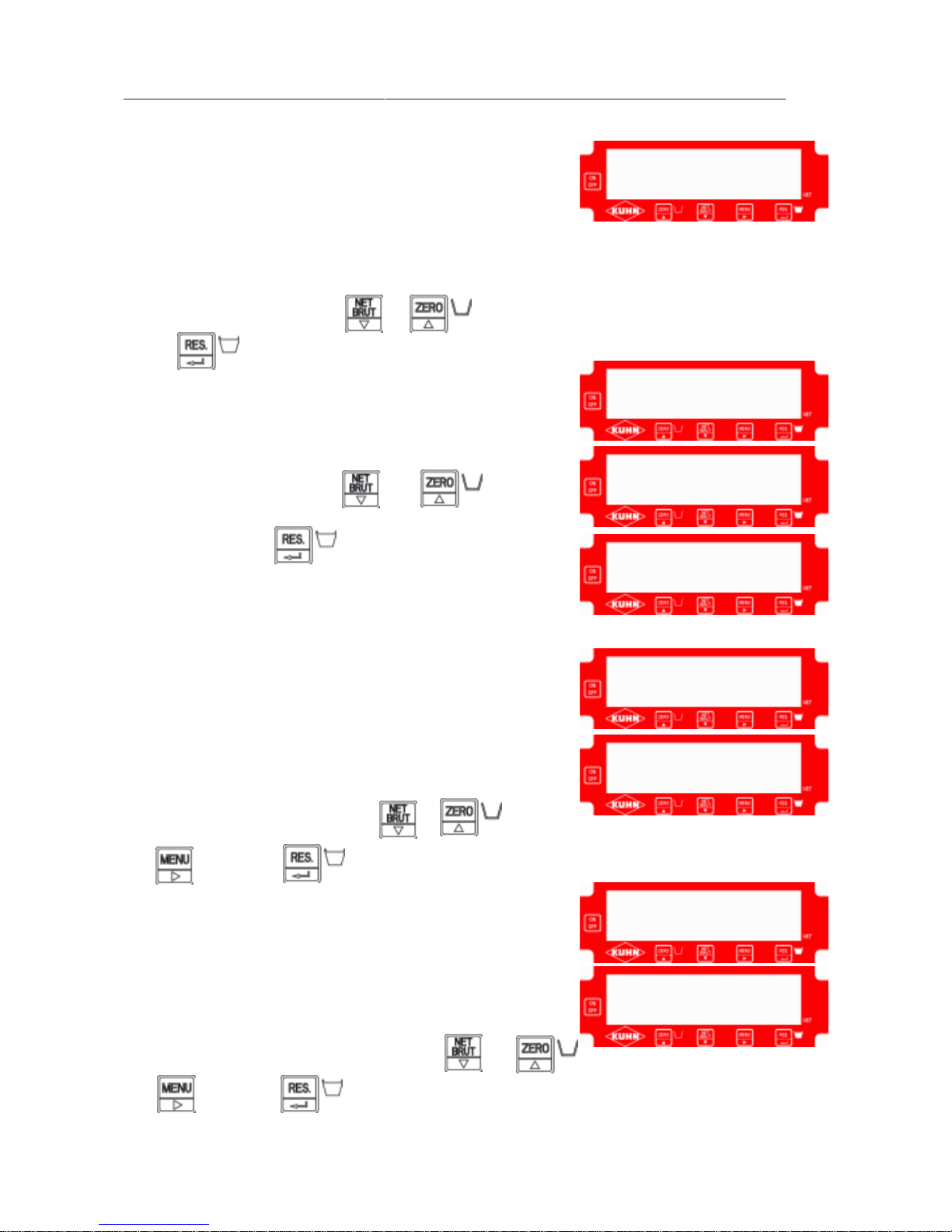
Retrieve the four values indicated in the junction box (on the
sticker):
- V alue 1
- V alue 2
- Measurement 1
- Measurement 2
Enter the maintenance menu (see
2.2.2).
Select function F3 by pressing or
Press to validate.
The message “
CALIB” appears briefly.
Select the unit of weight - “
SI” for kilograms or
“
LB” for pounds - by pressing or
V alidate by pressing
The message “
CAL 1” is displayed for one second.
The value 1 is displayed “
XXXXX”.
Display factory value 1 by pressing or
and then press to validate.
The message “
ACO 1” is displayed for one second.
Measurement 1 “
XXXXX” is displayed.
Display factory measurement 1 by pressing or
and then press to validate.
F 4
C A L I B
S I
L b
C A L 1
X X X X X
A C O 1
X X X X X
2.2.6 CALIBRA TING THE UNIT AT FOUR POINTS WITH FACTORY VALUES “F4”
 Loading...