

Page 1
1
MAINTENANCE MANUAL
For dealer technicians only
IND 360S STANDARD WEIGHING UNIT
IND 360P PROGRAMMABLE WEIGHING UNIT
Versions 1.1, 1.2 and 1.3
A7310180 4 04-2004
PLEASE READ CAREFULL Y BEFORE TESTING THE MACHINE
IND 900 STANDARD WEIGHING UNIT
Page 2

2
DEAR OWNER
In buying a KUHN machine you have chosen wisely . Into it have gone years of thought, research and
improvements. You will find, as have thousands of owners all over the world, that you have the best
that engineering skill and actual field testing can produce. You have purchased a dependable machine, but only by proper care and operation can you expect to receive the performance and long
service built into it.
This manual contains all the necessary information for you to receive full efficiency from your machine. The performance you get from this machine is largely dependent upon how well you read and
understand this manual and apply this knowledge. This is a simple machine but in which causes for
trouble are often overlooked even though apparent. These troubles are normally shown in poor work,
though they are largely due to natural wear of parts not being in original adjustment conditions. Therefore,
please DO NOT ASSUME THA T YOU KNOW HOW TO OPERA TE AND MAINT AIN YOUR MACHINE
before reading this manual carefully .
KEEP THIS MANUAL A V AILABLE FOR REFERENCE.
Y our KUHN dealer will instruct you on the general operation of your machine. He wants you to get the
best performance possible and will be glad to answer any special questions that may arise regarding
the operation of the KUHN machine.
Y our KUHN dealer can of fer a complete range of genuine KUHN service p arts.
These parts are manufactured and carefully inspected in the same factory that builds the machine to
assure high quality and accurate fitting of any necessary replacements.
ABOUT IMPROVEMENTS
KUHN is continually striving to improve its products and, therefore, reserves the right to make
improvements or changes when it becomes practical to do so, without incurring any obligations to
make changes or additions to the equipment sold previously .
Page 3

3
TABLE OF CONTENTS
1 - General ____________________________________________________ 4
1.1 Warning ________________________________________________ 4
1.2 General safety recommendations ____________________________ 5
1.3 Operating conditions ______________________________________ 6
1.3.1 Machines with chassis______________________________ 6
1.3.2 Machines without chassis ___________________________ 7
2 - IND 900 Standard Weighing Unit _______________________________ 9
2.1 Commissioning __________________________________________ 9
2.1.1 Electrical connection _______________________________ 9
2.1.2 Three-sensor machines_____________________________ 9
2.1.3 Four-sensor machines ______________________________ 10
2.2 Weighing unit maintenance _________________________________ 11
2.2.1 Switching on______________________________________ 11
2.2.2 Accessing the maintenance menu_____________________ 12
2.2.3 Description of the maintenance menu functions __________ 12
2.2.4 Testing the sensors ________________________________ 13
2.2.5 Calibrating the unit at two points ______________________ 14
2.2.6 Calibrating the unit at four points ______________________ 17
2.2.7 Auto-Power Off ___________________________________ 20
2.3 Troubleshooting __________________________________________ 21
2.4 Connecting to the junction box _______________________________ 24
3 - IND 360 Standard and Programmable Weighing Unit ______________ 26
3.1 Commissioning __________________________________________ 26
3.2 Weighing unit maintenance _________________________________ 28
3.2.1 Switching on______________________________________ 28
3.2.2 Simple maintenance _______________________________ 29
3.2.3 Specialized maintenance or self-testing_________________ 32
3.3 Troubleshooting __________________________________________ 35
3.4 Connecting to the printed circuit board ________________________ 38
4 - Options ____________________________________________________ 40
4.1 Luminous alarm (on IND 360) _______________________________ 40
4.2 Acoustic alarm (on IND 360) ________________________________ 40
4.3 Internal battery ___________________________________________ 40
4.4. IND 710 remote display ____________________________________ 41
5 - Removing and Refitting the Sensors and the Unit ________________ 42
51 General ________________________________________________ 42
5.2 Machines with chassis_____________________________________ 42
5.2.1 Removing and refitting the Ø 54 sensor_________________ 42
5.2.2 Removing and refitting the Ø 40 sensor_________________ 43
5.3 Machines without chassis __________________________________ 45
5.3.1 Removing the sensor_______________________________ 45
5.3.2 Refitting the sensor ________________________________ 46
5.4 Weighing unit ____________________________________________ 47
5.4.1 Removing and refitting the IND 900 unit _________________ 47
5.4.2 Removing and refitting the IND 360 unit _________________ 48
6 - Maintenance ________________________________________________ 49
7 - Limited Warranty ____________________________________________ 51
Page 4

4
This symbol is used throughout this manual wherever recommendations
are made concerning the safety of others, or good machine operation.
These recommendations must be made known to all machine operators.
PROPER USE OF THE MACHINE
The weighing unit must only be used for work for which it has been designed:
- Indication of the weight contained in the machine with, for the programmable version, the
possibility of programming animal rations.
The weighing unit must not be used for commercial transactions.
Proper use of the machine also means:
- following operation, maintenance and repair recommendations given by the manufacturer,
- using only spare parts, equipment and accessories as designated by the manufacturer.
The weighing unit must only be used, maintained and repaired by competent persons who are familiar
with the machine specifications and are aware of any danger involved.
The operator must observe current legislation concerning:
- accident prevention
- work safety
1. GENERAL
1.1 WARNING
Page 5

5
1.2 GENERAL SAFETY RECOMMANDATIONS
Before operating the machine, always ensure that the machine complies with work safety regulations.
GENERAL
1. Safety decals with recommendations to prevent accidents are placed on the machine.
2. Before carrying out work, ensure that the weighing unit is turned off.
3. Portable telephones can have a harmful effect on the working of the weighing unit.
USE
Before connecting the weighing unit to the tractor:
- check that the electric plug is clean and free from dirt,
- check that the electric circuit is correct.
MAINTENANCE
1. Disconnect from the power source before any work is done on the electrical system.
Before any electric welding is carried out on a machine that is attached
to the tractor, disconnect the tractor alternator and battery. Connect
the earth lead as close as possible to the part to be welded. Never
connect the earth to the chassis if the hopper is to be welded. If this
advice is ignored, then irreparable damage can be caused to the sensors
which connect the hopper and chassis.
Page 6

6
1.3 OPERATING CONDITIONS
1.3.1 MACHINES WITH CHASSIS
Type of machine: EUROMIX I, II and III, all models
AL TOR 9050 and 11050
TURBOMEL 7050, 9050 and 1 1050
Before responding to the message ‘Is the machine empty?’ (IND360) or “--0--” (IND900), ensure
that:
- The tractor engine is switched off.
- The machine is horizontal lengthways and widthways at the transport height; if not, refer to the
section on technical characteristics and tow bar adjustment in the user instructions.
- The machine is not exposed to strong wind.
- The transmission slides effortlessly.
- The chassis is well isolated from the body (check for stray product or foreign bodies).
- The machine’s components (arm, grab and tailgate) are in the idle position (see user instructions).
Page 7
7
1.3.2 MACHINES WITHOUT CHASSIS
Type of machine: ALTOR 4560, 6070, 7560 and 8060
A THENOR 6070, 7560 and 8060
ALTOR and ATHENOR 4560, 6070 & 7560
Before responding to the message ‘Is the machine empty?’ (IND360) or “--0--” (IND900), ensure
that:
- The tractor engine is switched off.
- The machine is horizontal lengthways and widthways at the transport height; if not, refer to the
section on technical characteristics and tow bar adjustment in the user instructions.
- The machine is not exposed to strong wind.
- The transmission slides effortlessly.
- The machine’s components (arm, grab and tailgate) are in the idle position (see user instructions).
- The brakes are off (parking and service brake) (see user instructions).
Sufficient clearance is required between the brake shoes and the drum;
any rubbing may cause incorrect weighing.
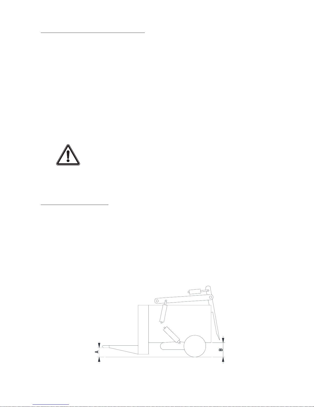
Adjusting the levelling sensor
- Set the body to height B from the ground and the towing eye bolt to height A, adjust the screw (1) to
position it opposite the sensor, then set the detection distance to approximately 3 mm (maximum
4 mm). The sensor indicator should then light up.
- Tighten the screw and the sensor onto their respective mountings.
- Check the body height setting. T o do this, lower the body to the ground, then raise it until the indicator
lights up and measure the body height. This must be equal to height B ± 10 mm.
If the measured distance is not correct, repeat the adjustment operation.
Page 8
8
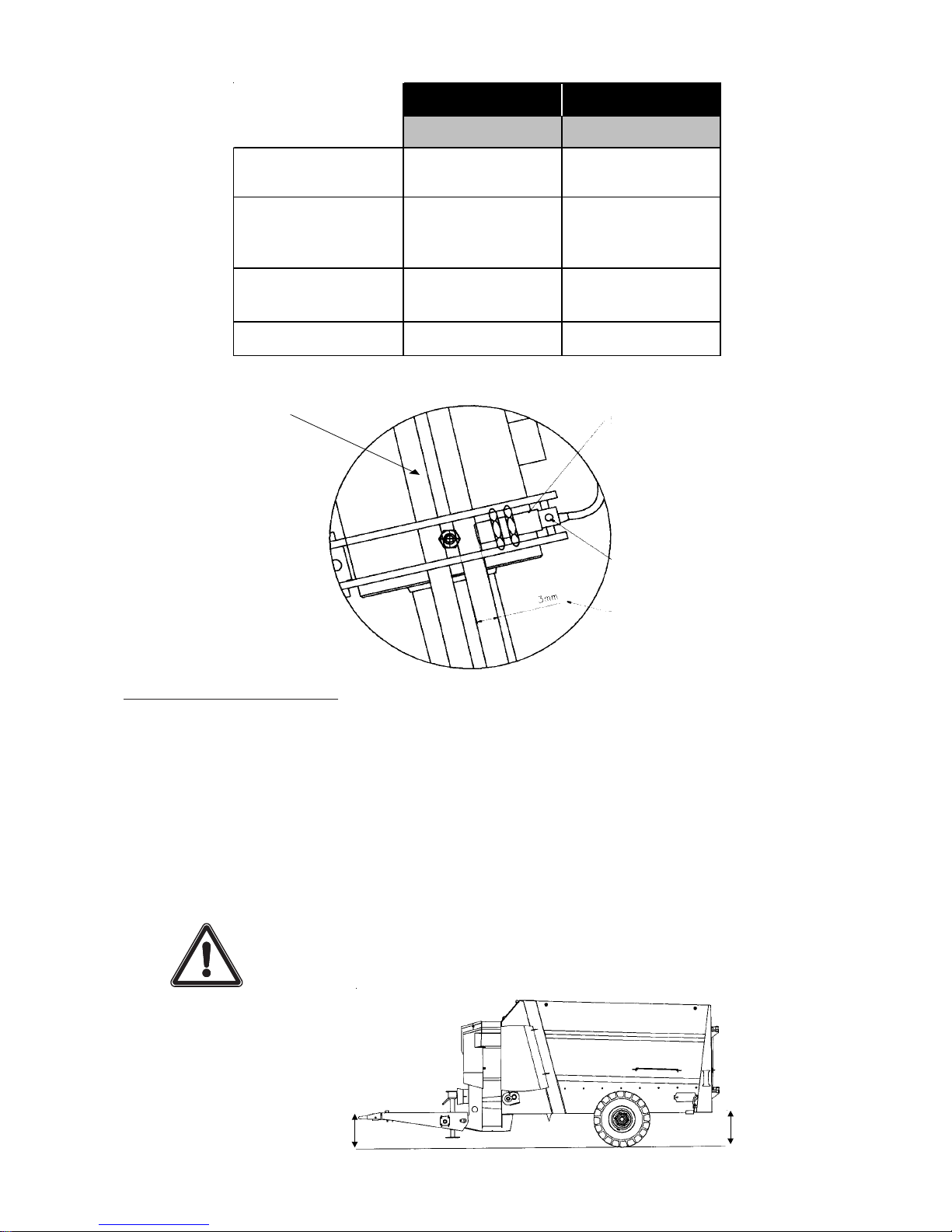
1
Inductive sensor
Indicator lamp
Detection distance
TOWBAR SILL
AB
4560
Short towbar
240 641
4560
Long towbar
(Position B2) *
272 641
6070
(Position B2) *
390 449
7560 332 545
* Refer to the user instructions for the machine.
355 mm
beneath
towing eye
512 mm
beneath body
Towbar setting: position B2
(refer to the user instructions for the machine)
ALTOR AND ATHENOR 8060
Before responding to the message ‘Is the machine empty?’ (IND360) or “--0--” (IND900), ensure
that:
- The tractor engine is switched off.
- The machine is horizontal lengthways and widthways at the transport height (see diagram); if not,
refer to the section on technical characteristics and tow bar adjustment in the user instructions.
- The machine is not exposed to strong wind.
- The transmission slides effortlessly.
- The machine’s components (arm, grab and tailgate) are in the idle position (see user instructions).
- The brakes are off (parking and service brake).
Sufficient clearance is required between the brake shoes and the drum;
any rubbing may cause incorrect weighing.
Page 9
9
2. IND 900 STANDARD WEIGHING UNIT
2.1 COMMISSIONING
Power supply 12 V (max. 17 V)
Protection against polarity reversal.
- Connect the power cable (A) to the + and - terminals of the tractor battery (beware not to reverse
polarity) and attach the socket to the rear of the tractor cab.
- Connect the unit to the power cable (A).
Before using the weighing unit in cold weather, leave it to warm up for at least ten minutes for a more
stable display .
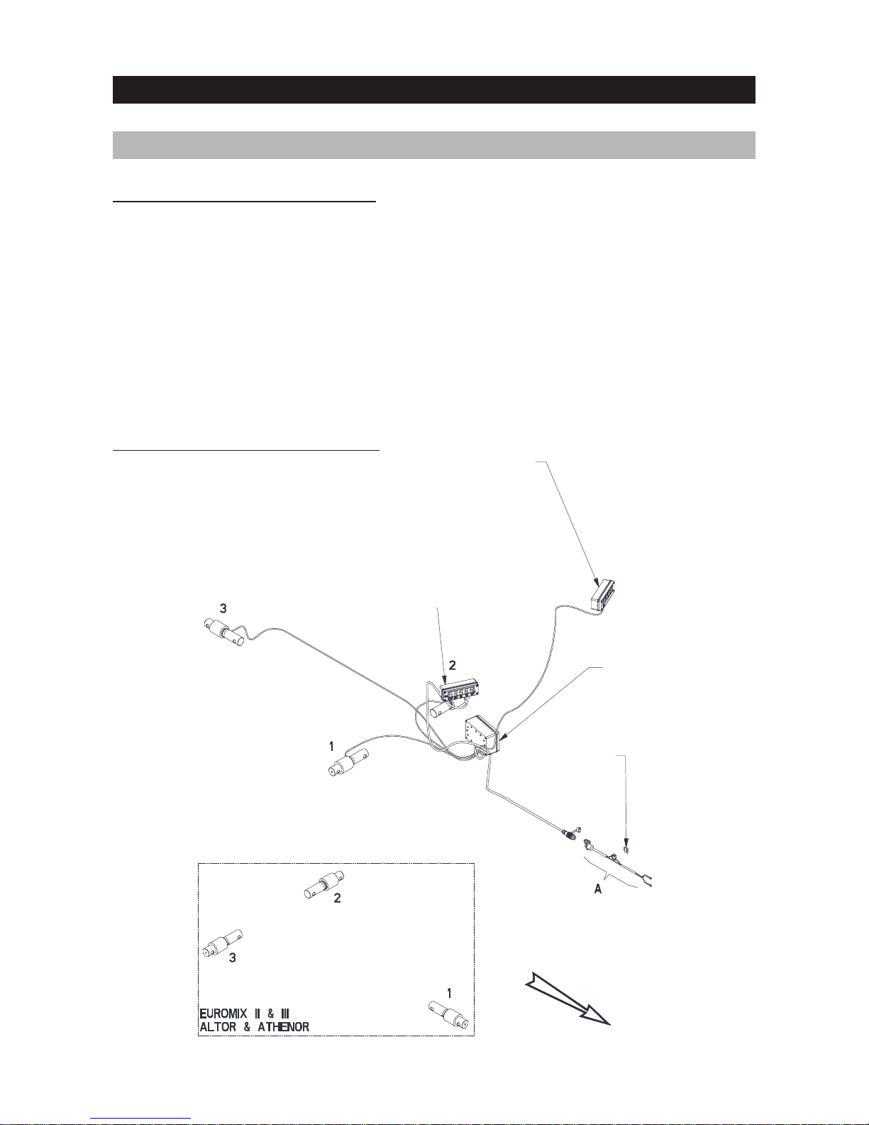
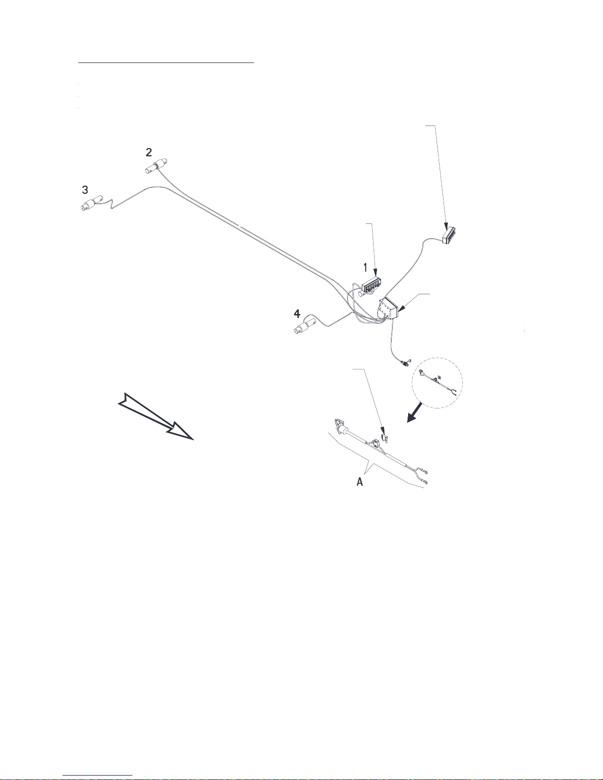
2.1.1 ELECTRICAL CONNECTION
Secondary display
3 sensors
Euromix I
Main indicator
Junction box
Fuse 15A
Ref. 83233017
Front
2.1.2 THREE-SENSOR MACHINES
Page 10
10
2.1.3 FOUR-SENSOR MACHINES
4 sensors
Euromix I
Euromix III 1050F - 1250F
Secondary display
Main indicator
Junction box
Fuse 15A
Ref. 83233017
Front
Page 11

11
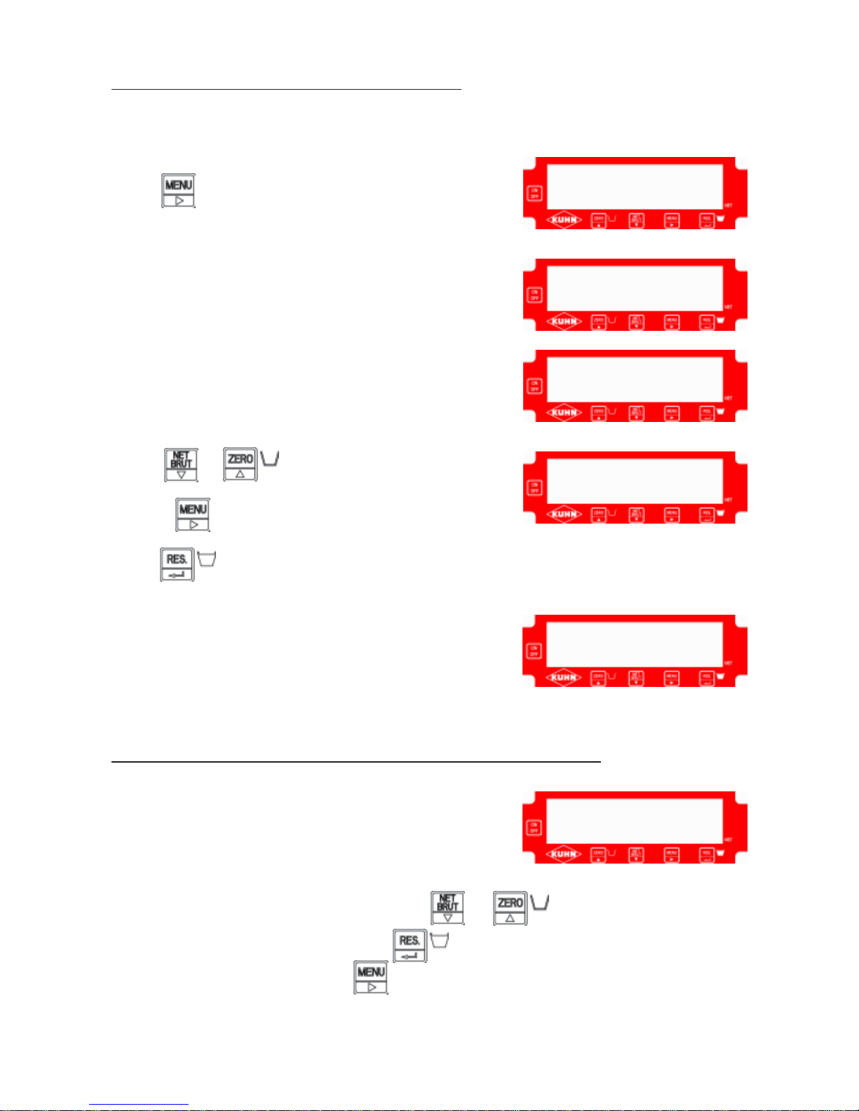
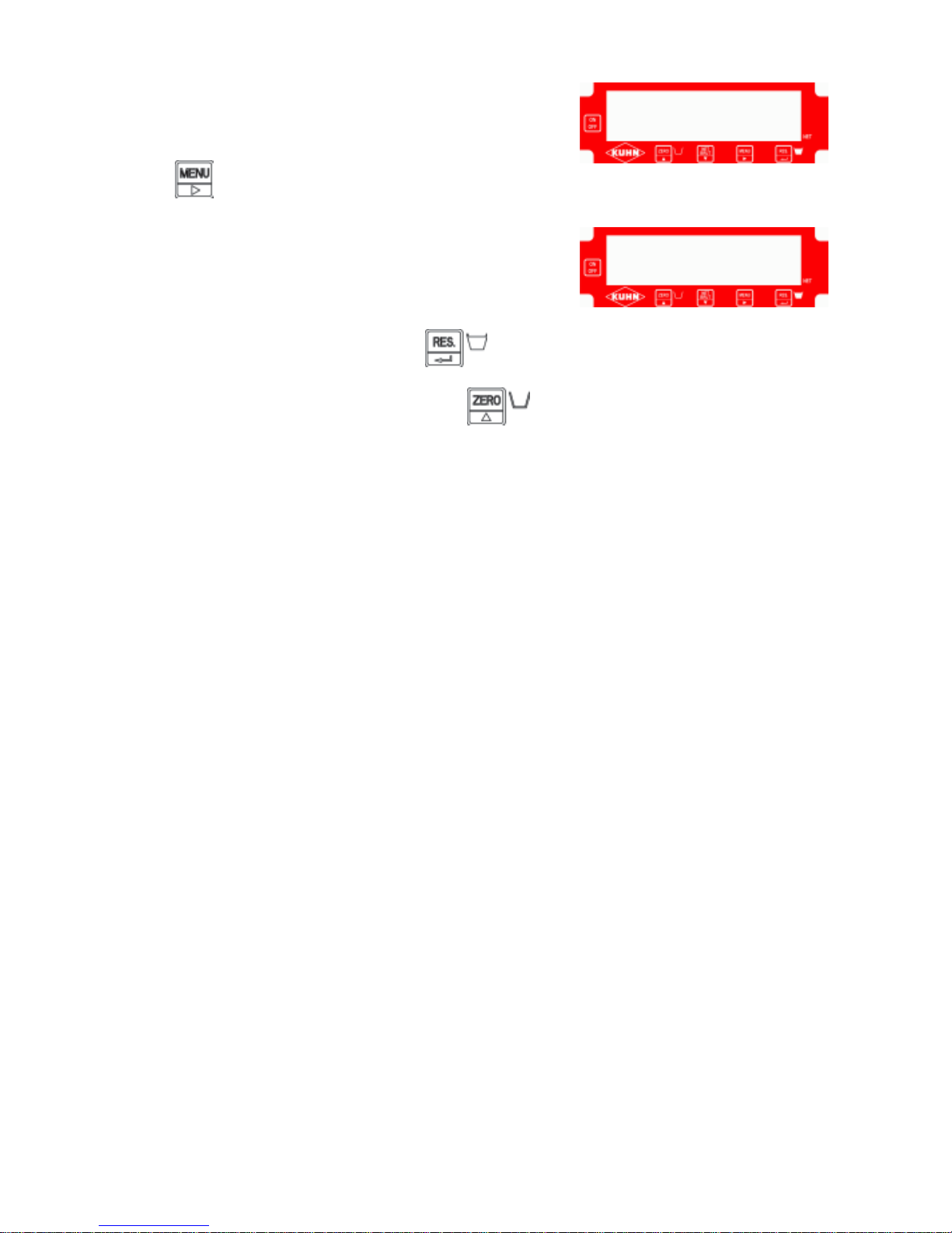
1 - Switch on the unit by pressing
2 - The message “- - - - -” is displayed for ten seconds.
3 - The message “
- - 0 - - “ flashes.
2.2 WEIGHING UNIT MAINTENANCE
- - - - -
2.2.1 SWITCHING ON
- - 0 - -
Page 12
12
Press
The message “
CodE” is displayed.
The message “
0.000” is displayed. Now enter the main-
tenance code “
5657”.
- Press or to decrease or increase a digit.
- Press to move onto the next digit.
Press to validate.
The message “
F1” is displayed.
F1: Choice between kilograms “
SI” or pounds “Lb”
F2: T wo-point calibration with a standard weight
F3: Sensor voltage test and display
F4: Four-point calibration with factory values
F5: Time-out setting (ON or OFF)
To select a function (F1, F2, F3, F4 or F5), press or
To enter or exit the selected function, press
To exit the maintenance menu, press (when
F1, F2, F3, F4 or F5 is displayed).
Switch on the unit.
- - 0 - C o d E
F 1
F 1
2.2.2 ACCESSING THE MAINTENANCE MENU
2.2.3 DESCRIPTION OF THE MAINTENANCE MENU FUNCTIONS
0.0 0 0
5 6 5 7.
Page 13
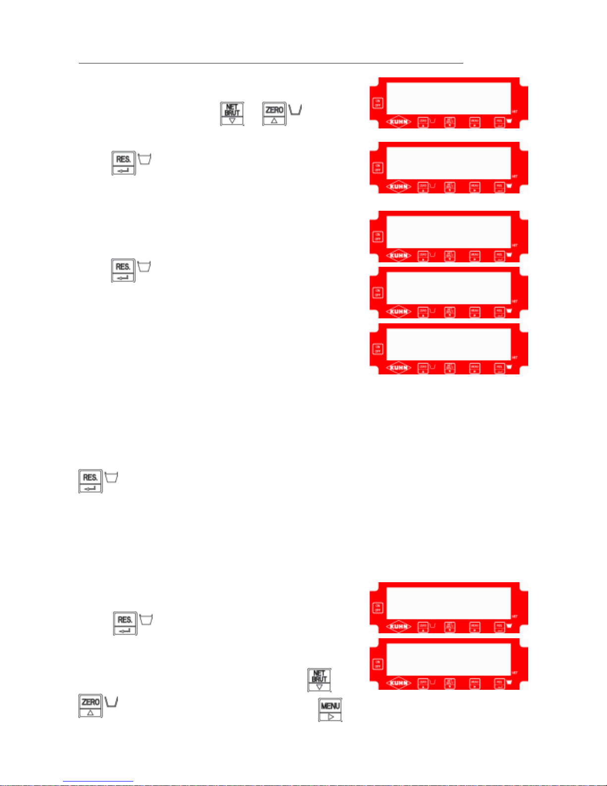
13
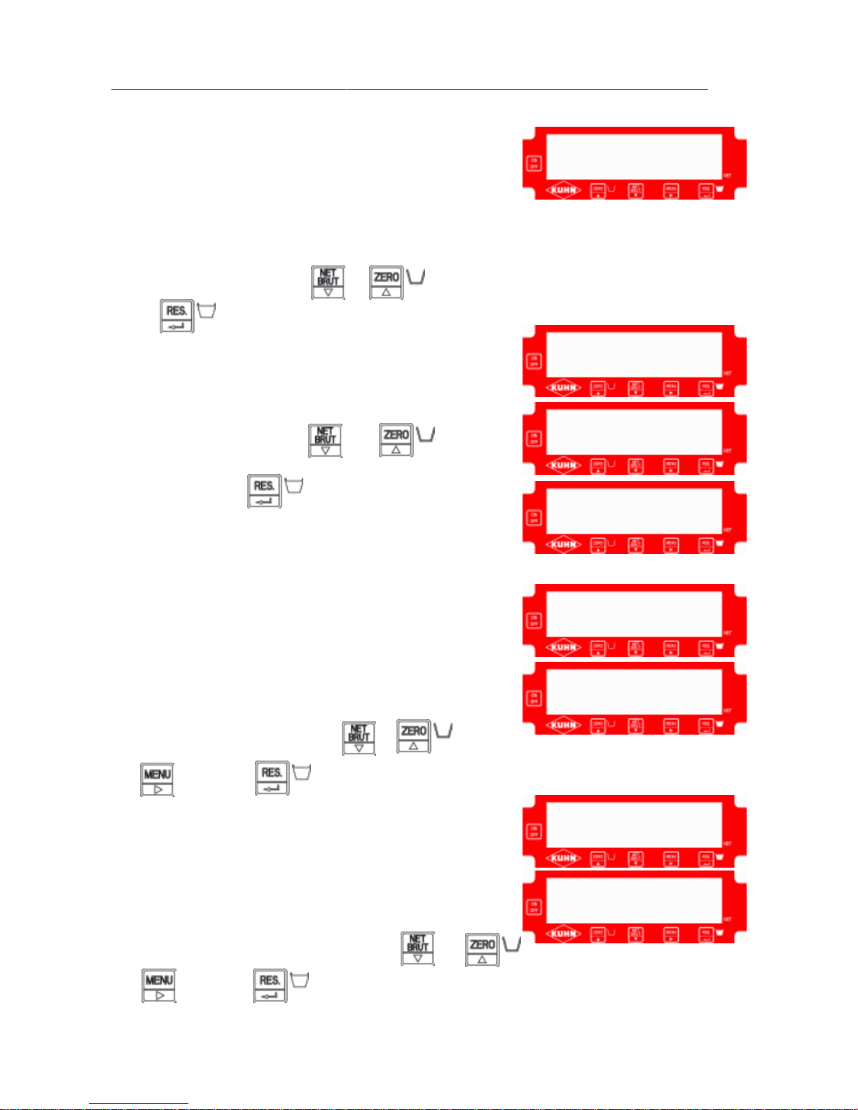
Enter the maintenance menu (see
2.2.2).
Select function F3 by pressing or
Disconnect the sensors in the junction box
Press to validate.
The message “
CELLS” is displayed indicating a sensor fault.
Press
The message “
CELL” is displayed briefly then the message
“
BAD” appears.
Reconnect the first sensor and wait two seconds. If the message “
Good” is displayed, no fault is
detected. If the message “
bad” continues to be displayed, the sensor is faulty (see the section on
connection, broken wire or faulty sensor problems).
Disconnect the first sensor, connect the second and wait for the “
Good” or “bad” diagnosis.
Repeat for each sensor. When the message “
Good” is displayed for the final sensor, press
The sensor voltage is displayed “
X.XXX” (in V).
Note the voltage on the test sheet.
Connect each sensor again one by one to display the
corresponding voltage.
Reconnect all sensors.
The total voltage is displayed “
X.XXX”.
Press to exit function F3.
The message “
F1” is displayed.
You can now choose another function by pressing or
or exit the maintenance menu by pressing
- - - - -
F 3
C E L L S
C E L L
B A D
F 1
2.2.4 TESTING THE SENSORS AND SENSOR VOLTAGE DISPLAYS “F3”
X.X X X
Page 14
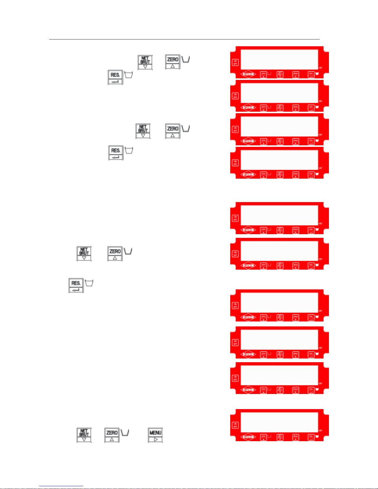
14
Enter the maintenance menu.
Select function F2 by pressing or
V alidate by pressing
The message “
CALIB” appears briefly.
Select the unit of weight - “
SI” for kilograms or
“
LB” for pounds - by pressing or
V alidate by pressing
The message “
CAL 1” is displayed for one second.
A value “
0” is displayed. If this value differs, reset to zero by
pressing or
Check that nothing is resting on the machine.
Press
The message “
AC0 1” is displayed and a dot scrolls across
the bottom of the screen.
(The weighing unit is calculating measurement 1. This
operation takes around 30 seconds).
The message “
CAL 2” is displayed for one second.
A value “
X.XXX” is displayed.
Display the value of the standard weight (e.g. 2327) by
pressing or and
F2
S I
C A L 1
0.
A C O 1
C A L I B
L b
2.2.5 CALIBRA TING THE UNIT AT TWO POINTS WITH A STANDARD WEIGHT “F2”
X.X X X
2 3 2 7.
C A L 2
Page 15

15
The message “
AC0 2” is displayed.
Measurement 2 is displayed “
XXXXX”.
Press
Lay the standard weight on the machine.
Press
The message “
AC0 2” is displayed and a dot scrolls across
the bottom of the screen.
(The weighing unit is calculating measurement 2. This
operation takes around 30 seconds).
The message “
CAL 1” is displayed.
V alue 1 displays “
0” intermittently .
Press
The message “
AC0 1” is displayed.
Measurement 1 is displayed “
XXXXX”.
Press
The message “
CAL 2” is displayed.
Value 2 is displayed “
XXXXX” (2327 for the factory standard
weight, for example).
Press
0
A C O 2
C A L 1
A C O 1
X X X X X
C A L 2
2 3 2 7
X X X X X
A C O 2
Page 16
16
The message “
F1” is displayed.
Press to exit the maintenance menu.
The message “
- - 0 - -” flashes.
If the weight is still on the machine, press
If the weight is no longer on the machine, press
The weighing unit has left maintenance mode and is running normally.
To check that the unit is in good working order:
- carry out successive measurements of the standard weight
- reset to zero.
- - 0 - -
F 1
Page 17
17
Retrieve the four values indicated in the junction box (on the
sticker):
- V alue 1
- V alue 2
- Measurement 1
- Measurement 2
Enter the maintenance menu (see
2.2.2).
Select function F3 by pressing or
Press to validate.
The message “
CALIB” appears briefly.
Select the unit of weight - “
SI” for kilograms or
“
LB” for pounds - by pressing or
V alidate by pressing
The message “
CAL 1” is displayed for one second.
The value 1 is displayed “
XXXXX”.
Display factory value 1 by pressing or
and then press to validate.
The message “
ACO 1” is displayed for one second.
Measurement 1 “
XXXXX” is displayed.
Display factory measurement 1 by pressing or
and then press to validate.
F 4
C A L I B
S I
L b
C A L 1
X X X X X
A C O 1
X X X X X
2.2.6 CALIBRA TING THE UNIT AT FOUR POINTS WITH FACTORY VALUES “F4”
Page 18

18
The message “
CAL 2” is displayed for one second.
V alue 2 “
XXXXX” is displayed.
Display factory value 2 by pressing or
and then press to validate.
The message “
ACO 2 is displayed for one second.
Measurement 2 “
XXXXX” is displayed.
Display factory measurement 2 by pressing or
and then press to validate.
The message “CAL 1” is displayed.
V alue 1 “
XXXXX” is displayed for verification.
Press
The message “
ACO 1” is displayed.
Measurement 1 “
XXXXX” is displayed for verification.
Press
C A L 2
X X X X X
A C O 2
X X X X X
C A L 1
X X X X X
A C O 1
X X X X X
Page 19

19
The message “
CAL 2” is displayed.
V alue 2 “
XXXXX” is displayed for verification.
Press
The message “
ACO 2” is displayed.
Measurement 2 “
XXXXX” is displayed for verification.
Press
The message “
F1” is displayed.
Press
to exit the maintenance menu
The message “
- - 0 - -” flashes.
Press
The weighing unit has left maintenance mode and is running normally .
To check that the unit is in good working order:
- carry out successive measurements of a known weight
- reset to zero.
- - 0 - -
C A L 2
X X X X X
A C O 2
X X X X X
F I
Page 20

20
2.2.7 AUTO-POWER OFF
This function is used to turn off the IND 900 automatically
one hour after switching on.
Enter the maintenance menu (see 2.2.2)
Select function F5 by pressing or
Press to validate.
The message “
T-out” is displayed to indicate that you have
entered the time-out menu.
Then the message “
ON” or “OFF” is displayed.
Select ON or OFF by pressing or
(this activates or deactivates the AUTO-POWER OFF
function).
Press to validate.
The message “
F1” is displayed to indicate that you have left
function F5.
Press
to exit the maintenance menu.
F 5
T - O U T
O N
F 1
Page 21

21
Fault: The weighing unit does not come on when the power is switched on.
Cause: the indicator’s operating temperature range is -30 to +50°C.
- Check that the temperature is not outside the operating limits.
Cause: the indicator’s operating voltage is 12 Volts (maximum 17 V olts). It is protected by a 15A fuse.
- Check that the +/- polarity is correct.
- Check the power supply voltage: this should be within the range 11 to 17 V olt s d.c.
Warning: the indicator does not accept a.c.
- Check the connection to the tractor.
- Check the power supply cable fuse (15 A).
- For machines equipped with an internal battery, check the 2 A fuse.
- If the fuse is faulty, replace it: fuse type 5x20 2A.
- If these checks fail to reveal any reason for the fault, replace the weighing unit (see the section on
“Fitting and removing the sensors and the unit”).
Fault: The screen displays the ‘BAT’ message.
- The tractor power supply voltage has dropped below 11 V.
- For machines equipped with an internal battery , recharge the battery (see the section “Option: internal
battery life”).
Fault: The weight is not correct.
Cause: If the indicator displays 0 when the machine is loaded, the machine has been declared as
empty when it is full: refer to the section on “Restoring the factory zero setting” in the user instructions.
- Check that the machine meets the specified operating conditions (see the section on “Operating
conditions”).
- Check the connections between the sensors and the circuit board and the condition of the wiring.
- Test the sensors (see 2.2.4) to check the condition of the board and each sensor.
- If the sensors are in working order, and the operating conditions are satisfactory, calibrate the unit
again (see 2.2.5 or 2.2.6).
Fault: The weight is not stable. The display varies while the tractor engine is off.
- Check that the machine meets the specified operating conditions (see the section on “Operating
conditions”).
- Check the connections between the sensors and the circuit board and the condition of the wiring.
- Test the sensors (see 2.2.4).
- Check that the power supply voltage is stable. If not, check that the power supply is correctly
connected to the tractor battery. If the connection is OK, check the tractor’s electrical installation.
- If the power supply voltage is stable, check the voltage stability of each sensor and change the
sensor concerned.
- If these checks fail to reveal any reason for the fault, replace the weighing unit (see section “Fitting
and removing the sensors and the unit”).
2.3 TROUBLESHOOTING
Page 22

22
Fault: After moving, the indicator no longer displays the same value.
- Check that the machine meets the specified operating conditions (see the section on “Operating
conditions”).
- Check the connection of the sensors in the junction box and the condition of the wiring.
- Test the sensors (see 2.2.4).
- Check that the power supply voltage is stable. If not, check that the power supply is correctly
connected to the tractor battery. If the connection is OK, check the tractor’s electrical installation.
- If the power supply voltage is stable, check the voltage stability of each sensor.
- If these checks fail to reveal any reason for the fault, use the self-test sensor voltage display to note
the value of each sensor, then move the machine and note the new values of each sensor . The sum
of the voltages before and after moving should be the same.
- If they are different, there is a mechanical problem. Check again that the machine meets the specified
operating conditions (see the section on “Operating conditions”).
Fault: The indicator displays “
- - - - -” or “8 8 8 8 8”.
- Switch off your weighing unit and contact your approved Kuhn dealer to get your unit checked.
Fault: The message “
C E L L” appears on the screen.
- The indicator is signalling a sensor problem. Contact your approved Kuhn dealer to get the condition
of the sensor cables and connections and the working order of each sensor checked.
Page 23

23
NOTES
Page 24

24
2.4 CONNECTING TO THE JUNCTION BOX
Power supply
IND900
Secondary display IND710
Sensor no 1
Sensor no 2
Sensor no 3
Sensor no 4
Auxiliary battery
(Optional)
DEFLECTION SENSOR
Ø54
STUB AXLE
SENSOR Ø40
sens or 1 Measurement+ Whi te Yell ow/Green
sens or 1 Measurement- Green Black Front
sens or 1 P ower+ Red Brown LH front (4 sensors
)
sens or 1 P ower- Black Blue
sens or 1 S hiel di ng Transparent Black (large Ø)
sens or 2 Measurement+ Whi te Yell ow/Green
sens or 2 Measurement- Green Black
sens or 2 P ower+ Red Brown LH rear
sens or 2 P ower- Black Blue
sens or 2 S hiel di ng Transparent Black (large Ø)
sens or 3 Measurement+ Whi te Yell ow/Green
sens or 3 Measurement- Green Black
sens or 3 P ower+ Red Brown RH rear
sens or 3 P ower- Black Blue
sens or 3 S hiel di ng Transparent Black (large Ø)
sens or 4 Measurement+ Whi te Yell ow/Green
sens or 4 Measurement- Green Black
sens or 4 P ower+ Red Brown RH front (4 s ensors
)
sens or 4 P ower- Black Blue
sens or 4 S hiel di ng Transparent Black (large Ø)
Page 25

25
BA T. AUX.+: auxiliary battery red wire; indicator lamp brown wire
BA T .AUX.-: auxiliary battery blue wire; indicator lamp blue wire
Alim+: brown
Alim -: blue
Aff+: brown
Tx: yellow/green Secondary display
Aff-: blue wire and brown wire
}
TESTING OF SENSORS BU05 (∅ 40) AND FL05 (SHAFT)
Power impedance (between power+ and power-): from 350
Ω to 410 Ω
Measurement impedance (between measurement+ and measurement-): from 350 Ω to 355 Ω
Sensor insulation (between shielding and each wire from the sensor): over 20 Giga Ω
TESTING OF DEFLECTION SENSORS (
∅ ∅
∅ ∅
∅ 54)
Power impedance (between power+ and power-): 375 ± 10
Ω
Measurement impedance (between measurement+ and measurement-): 350 ± 5 Ω
Page 26

26
A
Power supply 12 V (max. 17 V)
complete with 15 A fuse
- Connect the power cable (A) to the + and - terminals of the tractor battery (beware not to
reverse polarity) and attach the socket to the rear of the tractor cab.
- Connect the unit to the power cable (A).
When switching on, the unit should emit a beep.
Before using the weighing unit in cold weather , leave it to warm up for at least ten minutes for a more
stable display .
Possibility of plugging in an additional alarm with 24 W maximum power (beware of the + and polarity of the alarm).
EUROMIX I, II & III
1
2
3
3
2
1
3 sensors with chassis 4 sensors with chassis
1
2
3
1
2
3
1
2
3
4
1
2
3
1
2
3
4
EUROMIX 1
EUROMIX 1 , 2 , 3 montage 3
EUROMIX 3 1050F - 1250F montage 4
Avant
Front
Vorn
G.
L.
L.D.R.R.Avant
Front
VornG.L.L.D.R.R.
Fuse 15 A
Ref. 83233017
Fuse 15 A
Ref. 83233017
3. IND 360 STANDARD AND PROGRAMMABLE WEIGHING UNIT
3.1 COMMISSIONING
Page 27

27
ALTOR & ATHENOR
3 sensors without chassis
3
2
1
1
3
2
Avant
Front
Vorn
G.
L.
L.
D.
R.
R.
Display
Audible alarm
Visible alarm
Detector
15 A Fuse
Ref. 83233017
- blue
+ brown
A
Printer
Body height indicator
Page 28

28
3.2.1 SWITCHING ON
Switch on the weighing unit at the on/off switch.
Check that the machine is suitable for the working conditions (see section “Operating conditions”).
If a blank blue screen appears when switched on, the voltage of the unit is too weak (below
11 V). Check the electrical supply.
Press to display the help page, press a second time to go back to the screen.
- If the machine is empty, press YES.
If there is still some product in the machine, the indicator
will ask “Are you sure the machine is empty?”. Press
YES again if it is empty.
- If the machine is loaded, press NO to display its contents.
WARNING
If you press YES by mistake when the machine is loaded and answer YES to the question “Are you
sure the machine is empty?”, then the weighing unit will indicate 0. To display the contents of the
machine, refer to the maintenance manual (see 3.2.2.3 “Reinstating the tare”).
3.2 WEIGHING UNIT MAINTENANCE
Are you s ure the machine
is empty ?
yes no
?
Page 29

29
3.2.2 SIMPLE MAINTENANCE
PROGRAMMABLE VERSION (IND 360P): first go to the GENERAL MENU
To access to the MAINTENANCE MENU, press and the key to the left of the key at the
same time.
Press to display the help page, press a second time to go back to the GENERAL MENU.
1- SENSOR TEST. Press key 1 to check the state of the
sensors (see description in 3.2.2.1).
2- CALIBRATION. Press key 2 to calibrate the weighing
unit (for example, if you have changed a sensor, see
3.2.2.2).
3- CONFIRMATION OF THE TARE. Press key 3 to re-tare
the weighing unit to its original setting (see 3.2.2.3).
4- DELETING OF THE PROGRAMS
Press key 4 to delete all programs (see 3.2.2.4).
Press the EXIT key to return to the GENERAL MENU.
3.2.2.1 SENSOR TEST
Press to display the help page, press a second time to return to sensor test.
Press key 3 if the machine has 3 sensors.
Press key 4 if the machine has 4 sensors.
3 sensors: all straw blowers and mixers, EUROMIX 8 N
and F and 10, 12 N.
4 sensors: EUROMIX 10 and 12 F .
N.B. If a 4-sensor test is selected for a machine which is
equipped with 3 sensors, the display will read “sensor 4 in
failure”. If the 3 sensors are not correctly connected to the
board, the display will read “sensor 1 in failure”.
As an example, we shall choose a test for a machine
equipped with 3 sensors.
All sensors are good.
Press EXIT to return to the MAINTENANCE MENU
IN THE EVENT OF A FAULT, RUN THE SELF-TEST (see § D1.6 “DISPLAYING THE
VOLTAGE OF THE SENSORS”)
?
MENU MAINTENANCE
1 - Sensor test
2 - Calibration
3 - Confirmation of the tare
4 - Deleting of the programs
1 2 3 4 5 Exit
SENSORS TEST
Test of three sensors
Sensor No 1 good
Sensor No 2 good
Sensor No 3 good
EXIT
SENSORS TEST
Number of sensors ?
3 4 EXIT
OK
OK
?
Page 30

30
3.2.2.2 CALIBRATION USING A KNOWN WEIGHT
TO MAKE USE OF THIS FUNCTION, YOU NEED A KNOWN WEIGHT
OF AT LEAST ONE TONNE
(see 3.2.2.1, Calibration without a known weight, from factory data)
To avoid any mistakes, before you begin machine calibration, check the sensors with the
help of the function in 3.2.3.1 “Testing the sensors”.
Enter the code 5141 with the modification keys X... , .X.. , ..X. and ...X at the bottom of the screen.
Press to validate the code (a mistake will involve returning to the Maintenance menu).
Machine empty
Enter 0000, then press . Do not touch the machine
while “Wait a minute, please” is displayed.
Machine loaded with the known weight.
Enter the second value, for example the value of the factory
known weight: 2135.
Do not touch the machine while “Wait a minute, please” is
displayed.
The screen then displays the calibration caracteristics. The
factory calibration caracteristics are printed inside the unit.
These are usable for a calibration without a known weight
(see 3.2.3.1 Acquisition of the st andard values).
Press EXIT to return to the MAINTENANCE MENU.
OK
CALIBRATION
Empty machine: 0 0 0 0
Wait please
Loaded machine: 2.1.3.5
Wait please
EXIT
OK
Page 31

31
3.2.2.3 CONFIRMATION OF THE TARE
This function can be used to find the contents of the machine if, when switching on, you confirmed
that the machine was empty although the machine was actually loaded.
Press to display the help page, press a second time to return to TAKE AGAIN THE ORIGINAL
TARE.
Answer YES to retrieve the zero from the factory calibration.
Answer NO to return to the MAINTENANCE MENU without
retrieving the zero from the factory calibration.
After returning to the factory calibration zero, there may be a difference compared with actual machine
contents. This difference can come from the fact that the machine was perfectly empty during calibration
in the factory but the return to zero has been done with a little product still inside the machine.
?
3.2.2.4 DELETING OF THE PROGRAMS
This function allows you to delete all programs memorized by the weighing unit.
Press to display the help page, press again to return to DELETING OF THE PROGRAMS.
Answer YES to delete all programs.
Answer NO to delete nothing and return to the
MAINTENANCE MENU.
?
Do you want to go back to
factory calibration ?
YES NO
Are you sure you want to
delete programms ?
YES NO
Page 32

32
3.2.3 SPECIALIZED MAINTENANCE OR SELF-TESTING
3.2.3.1 SELF-TEST AND SENSORS
RUNNING THE SELF-TEST , CALIBRA TION WITHOUT A KNOWN WEIGHT
AND CONFIRMA TION OF THE VOL TAGE OF THE WEIGHING UNIT
AND THE SENSORS.
To enter this function, press and at the same time when the weighing unit is first switched
on and the KUHN symbol has flashed three times. The weighing unit then requests the “Confidential
code”. With the function keys (X... , .X.. , ..X. , ...X), enter the code 5657 and validate by pressing
.
As soon as you validated the SELF-TEST, the buzzer sounds.
If you hear the buzzer, this means that it is running.
If the buzzer does not sound, check the connection of the wires (refer to the diagram of the printed
circuit board).
Screen test
Press to reset the screen (LCD) and check there is no fault.
Key test
Press the keys one by one. You will see the number corresponding to the key you have just pressed
in the middle of the screen, in place of the X. Key = 1 ..... key = 8
To exit the keyboard test, press and at the same time.
If a printer is connected to the machine, a printer test will be carried out (the printer has to be on
standby).
Test ticket
Y
ABCDEFGHIJKLMNOPQRSTUVWX
?
OK
OK
OK
OK
? OK
?
Page 33

33
Acquisition of the standard values (calibration without a known weight)
- If you do not want to proceed with theoretical calibration, press 4 times.
- If you do want to calibrate the weighing unit without the use of a weight and with the help of the
factory data, enter the values printed inside the unit with the help of functions (X... , .X.. , ..X. , and
...X) and validate each value by pressing .
OK
OK
Press the EXIT key to continue with the SELF-TEST
Testing the printed circuit voltages
Supply voltage of the electric battery (min. 12 V - max.
13.8 V)
Supply voltage of the CPU card (5 V +/- 0.5)
Contrasted power supply LCD voltage
(15 V +/- 0.5)
Sensor excitation voltage (8 V)
Supply voltage of the electric battery after protection
(min. 11 V).
Threshold of the Low voltage alarm.
Press the EXIT key to continue with the SELF-TEST
SENSOR EXCITATION VOLTAGE
Refer to the electronic circuit board connection diagram.
- If the voltage is less than 7.5 V, disconnect all the sensors from the circuit board and read the
excitation voltage again.
- If this voltage is still less than 7.5 V, there is a problem with the circuit board: change the weighing
unit.
- If it returns to 8 V, connect the sensors one by one and check if the voltage drops each time the
sensor is connected. As soon as the voltage drop s, this means the sensor that has just been connected
is faulty - replace it.
POWER SUPPLY VOL TAGE : 12 VOLTS
VOLTAGE + 5V : 05.0 VOLTS
VOLTAGE +15 V : 15.0 VOLTS
VOLTAGE + 8 V : 08.0 VOLTS
VOLTAGE + 11 V : 12.0 VOLTS
Power supply alarm 11.0 Volts
EXIT
NUMBER OF THE V ALUES
CALIBRA TION SENSOR
Sensor No 1: ........................ V alue No 1 : ...................
Sensor No 2: ........................ V alue No 2 : ...................
Sensor No 3: ........................ Mesure No 1: .................
Sensor No 4: ........................ Mesure No 2: .................
Label
V alues to be entered
Page 34

34
Displaying the sensor voltages
Press key 1 to display the voltage of sensor No 1
Press key 2 to display the voltage of sensor No 2
Press key 3 to display the voltage of sensor No 3
Press key 4 to display the voltage of sensor No 4
Press the EXIT key to exit the SELF-TEST and start the weighing unit
Display of the sensor voltage:
SENSOR l:
SENSOR 2:
SENSOR 3:
SENSOR 4:
1 2 3 4 EXIT
- If the voltage displayed is greater than 18 mV, check that the sensor is properly connected to the
circuit board and that the wire is not broken or crushed along its route to the unit. If everything is OK,
change the sensor.
* Refer to the electronic board connection diagram to identify the faulty sensor .
- If the voltage displayed is unstable, change the sensor.
- If the voltage displayed is preceded by the ‘-‘ sign:
· the measurement + / - connections on the sensor are the wrong way round
· the power + / - connections on the sensor are the wrong way round
* Refer to the electronic board connection diagram and check the connection of the wires: colour
coding, board connection and the link between the connector and wire on the screw terminals.
· the sensor is mounted upside down
* Refer to the section on fitting/removing sensors
SENSOR DIAGNOSTICS
3.2.3.2 PRINTER SELF-TEST (optional)
Standard self-test ticket
To run a printer self-test, press the paper feed button and, at the same
time, switch the printer on. The self-test starts after the paper feed button
has been held down for a second or two.
Release the paper feed button as soon as the self-test starts.
If the self-test does not run, check that:
. the power supply is OK (adequate voltage)
. the printer is correctly connected to the board (refer to the
electronic board connection diagram).
. If the ticket is identical to the standard ticket, the printer is working
correctly.
If not, check that:
. the ribbon is not worn
. the paper roll has paper left on it
. the paper is being fed through correctly.
Page 35

35
3.3 TROUBLESHOOTING
Fault: The weighing unit does not come on when the power is switched on
Cause: the indicator’s operating temperature range is -20 to +50°C
- Check that the temperature is not outside the operating limits.
No audible signal is heard
Cause: the indicator’s operating voltage is 12 Volts (maximum 17 Volts). It is protected by a 15A
fuse.
- Check that the +/- polarity is correct.
- Check the power supply voltage: this should be within the range 11 to 17 V olts d.c.
Warning: the indicator does not accept a.c.
- Check the connection to the tractor.
- Check the power supply cable fuse (15 A).
- For machines equipped with an internal battery, check the 2 A fuse.
- If the fuse is faulty, replace it: fuse type 5x20 2A.
The audible signal is heard
- Check the power supply voltage, this should be within the range 11 to 17 V olts d.c.
- For machines equipped with an internal battery, recharge the battery (see the section “Option:
internal battery life”).
- If the voltage is correct, adjust the display contrast as this may vary with temperature:
- for units made before April 1998, see adjustment on the board connection diagram, page 24
- for units made later than April 1998, adjust the contrast button on the front of the unit.
If these checks fail to reveal any reason for the fault, replace the weighing unit (see the section on
“Fitting and removing the sensors and the unit”).
Fault: The screen displays a ‘battery low’ message
This message is displayed in two situations:
1. The tractor power supply voltage has dropped below 11 V
For machines equipped with an internal battery , recharge the battery (see the section “Option:
internal battery life”).
2. There is a problem on the printed circuit board or a sensor (board and sensor monitoring)
In either case, run self-tests on the unit and sensors: see 3.2.3.1 “Testing the printed circuit voltages”
and “Displaying the sensor voltages”.
Fault: The weight is not correct
Cause: If the indicator displays 0 when the machine is loaded, the machine has been declared as
empty when it is full: refer to 3.2.2.3 (Confirmation of the tare).
- Check that the machine meets the specified operating conditions (see the section on “Operating
conditions”).
- Check the connections between the sensors and the printed circuit board and the condition of the
wiring.
- Run the self-tests on the unit and sensors: see 3.2.3.1 “Testing the printed circuit voltages” and
“Displaying the sensor voltages”.
- If the circuit board and sensors are all working properly and the operating conditions are correct,
carry out calibration as described in 3.2.2.2.
Page 36

36
Fault: The weight is not stable. The display varies while the tractor engine is off.
- Check that the machine meets the specified operating conditions (see the section on “Operating
conditions”).
- Check the connections between the sensors and the circuit board and the condition of the wiring.
- Run the self-tests on the unit: see 3.2.3.1.
- Check that the power supply voltage is stable. If not, check that the power supply is correctly
connected to the tractor battery. If the connection is OK, check the tractor’s electrical installation.
- If the power supply voltage is stable, check the voltage stability of each sensor and change the
sensor concerned.
- If these checks fail to reveal any reason for the fault, replace the weighing unit (see the section on
“Fitting and removing the sensors and the unit”).
Fault: Horizontal stripes appear on the screen
Cause: The weighing unit has suffered an impact
- Replace the weighing unit.
Fault: The screen is not legible
Cause: Insufficient lighting - the screen is partially or totally blank.
- Use a voltmeter to check that the indicator supply voltage is 12 V.
- For machines equipped with an internal battery, recharge the battery (see the section “Option:
internal battery life”).
- If the voltage is correct, adjust the weighing unit contrast using the potentiometer located on the
circuit board (for units made before April 1998 - see the section on circuit board connections), or for
units made later than April 1998, adjust using the contrast button on the front of the unit.
- If it is not possible to adjust the unit satisfactorily, replace the weighing unit (see the section “Fitting
and removing the sensors and the unit”).
Fault: After moving, the indicator no longer displays the same value
- Check that the machine meets the specified operating conditions (see the section on “Operating
conditions”).
- Check the connections between the sensors and the circuit board and the condition of the wiring.
- Run the self-tests on the unit: see 3.2.3.1.
- Check that the power supply voltage is stable. If not, check that the power supply is correctly
connected to the tractor battery. If the connection is OK, check the tractor’s electrical installation.
- If the power supply voltage is stable, check the sensor excitation voltage and the voltage stability of
each sensor.
- If these checks fail to reveal any reason for the fault, use the self-test sensor voltage display to note
the value of each sensor, then move the machine and note the new values of each sensor. The
sum of the voltages before and after moving should be the same.
- If they are different, there is a mechanical problem. Check again that the machine meets the specified
operating conditions (see the section on “Operating conditions”).
Page 37

37
Fault: The indicator displays ----
a) Immediately after answering YES or NO to the question “Is the machine empty?”
Cause 1: A sensor is faulty
- Carry out a self-test. If the sensors are correct, see Cause 2.
Cause 2: Calibration is not correct
- Repeat the calibration. See (3.2.2.2 “Calibration using a known weight”)
(3.2.3.1 to correct the standard values)
b) On the standard weighing unit, after unloading
Cause: The unloaded value is over 995 kg.
Page 38

38
3.4 CONNECTING TO THE PRINTED CIRCUIT BOARD
NF Secondary display connection
BAT+: Auxiliary battery red wire
BA T -: Auxiliary battery blue wire
BAT+: Indicator lamp brown wire
BA T-: Indicator lamp blue wire
AL+: Alarm red wire
AL-: Alarm blue wire
Printer or secondary display connection
DEFLECTION SENSO R
Ø54
STUB AXLE
SE NS OR Ø40
sens or 1 Measurement+ W hite Yell ow/G reen
sens or 1 Measurement- Green Black Front
sens or 1 P ower+ Red Brown LH front (4 sensors
)
sens or 1 P ower- Black Blue
sens or 1 S hiel di ng Transparent Black (large Ø)
sens or 2 Measurement+ W hite Yell ow/G reen
sens or 2 Measurement- Green Black
sens or 2 P ower+ Red Brown LH rear
sens or 2 P ower- Black Blue
sens or 2 S hiel di ng Transparent Black (large Ø)
sens or 3 Measurement+ W hite Yell ow/G reen
sens or 3 Measurement- Green Black
sens or 3 P ower+ Red Brown RH rear
sens or 3 P ower- Black Blue
sens or 3 S hiel di ng Transparent Black (large Ø)
sens or 4 Measurement+ W hite Yell ow/G reen
sens or 4 Measurement- Green Black
sens or 4 P ower+ Red Brown RH front (4 sensors
)
sens or 4 P ower- Black Blue
sens or 4 S hiel di ng Transparent Black (large Ø)
Page 39

39
TESTING OF SENSORS BU05 (
∅ 40) AND FL05 (SHAFT)
Power impedance (between power+ and power-): from 350
Ω to 410 Ω
Measurement impedance (between measurement+ and measurement-): from 350 Ω to 355 Ω
Sensor insulation (between shielding and each wire from the sensor): over 20 Giga Ω
TESTING OF DEFLECTION SENSORS (
∅ ∅
∅ ∅
∅ 54)
Power impedance (between power+ and power-): 375 ± 10
Ω
Measurement impedance (between measurement+ and measurement-): 350 ± 5 Ω
Page 40

40
4. OPTIONS
4.1 LUMINOUS ALARM
Voltage: 12 V - Max. current: 2 A
4.2 ACOUSTIC ALARM
Voltage: 12 V - Max. current: 250 mA
Acoustic power: 120 dB
Acoustic frequency from 1.5 to 4 kHz
4.3 INTERNAL BATTERY
Volt age: 12 V
Capacity: 2 Ah
Operating temperature: from -15 to +50°C
The battery is located inside the unit. Its capacity without recharging is 2 hours.
It is charged as soon as the socket is connected to the tractor’s electrical system. We advise
connecting the weighing unit to the tractor every time the tractor is coupled to the machine to keep
the battery permanently charged.
Never keep the weighing unit switched on for more than two hours with the internal battery . After
one hour, switch off the weighing unit or connect it to the tractor as there is a risk of running down
the internal battery charge.
BATTERY LIFE
Maximum usage time Charging time
* battery 100% charged
5 hours 10 - 14 hours
For a shorter usage time, the charging time will be reduced
Example: Battery 100% charged
Usage time: 1 hour
Charging time 2 to 3 hours
If the battery is not 100% charged, the battery life will be reduced in proportion.
STORAGE
When storing the machine, remove the battery from the weighing unit and store it in an appropriate
place.
Page 41

41
Power supply: 12 V , consumption 380 mA (in addition to the 400 mA indicator consumption - beware
when using with an internal battery).
LED display unit:
- height: 80 mm, width: 230 mm, depth: 65 mm
- operating temperature: -30°C to +50°C
Digit size: 55 mm high, 30 mm wide
Plastic casing:
- shockproof
- sealed to IP 65
Direct connection to IND 360 indicator unit (see 3.4)
Tx = Yellow/green NF = black A+ = brown A - = blue
Direct connection to IND 900 indicator unit (see 2.4)
Tx = Yellow/green Aff+ = brown Aff- = blue and black
CE approved.
If the secondary display fails to light up:
- Go to the IND360 main menu.
- Select “5. Options”, then “Print”, then “INACTIVE” (cf. User Manual).
4.4 IND700 REMOTE DISPLAY (Secondary display)
Page 42

42
This operation is to be carried out in a clean, damp-free building. If
these conditions are not observed, the weighing unit or sensors can
fail due to moisture and dust. Take all necessary precautions.
REASONS FOR REFUSAL OF W ARRANTY
Return of the sensor with the wire cut.
Return of the sensor or weighing unit in poor condition.
Return of a printed circuit board which is damaged or on which electronic
components have been disconnected.
Return of a sensor or weighing unit damages due to poor packaging.
Removal of the front panel on IND 900.
5. FITTING AND REMOVING THE SENSORS AND THE UNIT
5.2 MACHINES WITH CHASSIS
5.2.1 REMOVING AND REFITTING THE Ø 54 DEFLECTION SENSOR
Necessary tools:
24 mm spanner, crosshead screwdriver, small electrician’s screwdriver, mallet, slide hammer, axle
stand and bottle jack.
- Remove the front of the unit.
- Disconnect the faulty sensor, remove the connector and
unscrew the gland.
- Take the wire out of the unit and the protective sleeve.
- Remove any cable ties and free the sensor cable from the
rest of the machine.
- Check that the wire is not damaged as this could be the
cause of the failure.
- Remove the screws (1).
- Using a jack, lift the body near to the sensor
(6 to 7 cm) and secure with an axle stand.
- Remove the sensor carefully without dropping it (2).
5.1 GENERAL
Page 43

43
Necessary tools: 8 mm allen keys, 16 mm and 21 mm spanners, crosshead screwdriver, small
electrician’s screwdriver, mallet, slide hammer (10 mm), axle stand and bottle jack.
- Remove the front of the unit.
- Disconnect the faulty sensor, remove the connector
and unscrew the gland.
- Take the wire out of the unit and the protective sleeve.
- Remove any cable ties and free the sensor cable
from the rest of the machine.
- Check that the wire is not damaged as this could
be the cause of the failure.
- For the front sensor, after first putting a wedge under the
frame, dismantle the coupling shaft.
- Remove pin (2) from the sensor holder.
- Using a jack, lift the body near to the sensor
(2 to 3 cm) and secure with an axle stand.
- Remove the securing screw (1).
Removing from outside the machine
- Screw a slide hammer onto the sensor then extract the sensor with all due precaution.
- Remove the gasket (3).
- Remove the sensor and take the wire carefully out through the sensor housing.
Removing from inside the machine
- Using a mallet and a brass punch, carefully tap the sensor out without dropping it.
- Remove the gasket.
5.2.2 REMOVING AND REFITTING THE Ø 40 SHEAR SENSOR
1
2
3
- Before refitting the sensor, grease the mounting hole and the sensor.
- Fit the sensor with the arrow on the end of the sensor pointing down.
If the sensor is fitted the wrong way round, the weight indicated will be
incorrect.
- Insert the sensor into its housing, taking care not to damage the wire.
When refitting the sensor, it should slide into it s housing without being
forced. If the sensor does not go in easily, check the mounting hole;
repair or replace the mounting if necessary.
Connection
- Fit the wire onto the chassis and the body and thread it through the sleeve up to the unit.
- Connect the wires on the connector in the right order (see the section on “Connecting to the printed
circuit board”.
- Make sure that the front of the unit and all external fittings are watertight.
- Reposition the hopper on the sensor.
- Fit the screws (1).
Page 44

44
Before fitting a sensor, grease the gasket, the mounting hole and the sensor.
- Take the new sensor and feed the wire through the sensor holder.
- Fit the sensor with the cable on the right when viewing from the cable side.
If the sensor is fitted the wrong way round, the weight indicated will be
incorrect.
Fitting from the outside
- Put the sensor in its housing. Be careful not to damage the wire.
- Using the mallet, tap the sensor in and fit the gasket in the fork of the holder.
Fitting from the inside
- Put the sensor in its housing.
- Fit the gasket in the fork of the holder.
- Screw the slide hammer onto the sensor then pull the gasket and sensor into place.
- Refit the screws securing the sensor.
When refitting the sensor, it should slide into it s housing without being
forced. If the sensor does not go in easily, check the mounting hole;
replace the mounting if necessary.
Connection
- Fit the wire onto the chassis and the body and thread it through the sleeve up to the unit.
- Connect the wires on the connector in the right order (see the section on “Connecting to the printed
circuit board”.
- Make sure that the front of the unit and all external fittings are watertight.
- Reposition the hopper on the sensor.
- Refit the securing screw.
Page 45

45
1
2
3
20
10
1
2
3
11
18
13
14
15
16
17
19
21
5
6
7
4
8
9
12
Tools required:
24, 46 and 60 mm spanners, crosshead screwdriver, small electrician’s screwdriver, mallet, brass
punch, lifting rods and jack.
5.3.1 REMOVING THE SENSOR
- Take off the front of the unit.
- Disconnect the faulty sensor, remove the connector and unscrew the cable gland.
- Remove the wire from the weighing unit and from the protective sleeve.
- Take off the clamps and withdraw the wire along the body up to the sensor without damaging it.
- Check that the wire is not damaged, as this may have been the cause of the fault.
Rear sensor
- Raise the body high enough to be able to get the sensor out easily . Fit lifting rods under the body and
under the axle.
- Take off the wheel.
- Take off the brake drum: unscrew the cover (10) using a 60 mm sp anner , remove the pin (18), undo
the nut (11) using a 46 mm spanner and remove the washer (12).
- Take out the bearings (13) and (15), then remove the washer (16) and seal (17).
- Remove the pin (19).
- Remove the sensor, taking care to bring the wire through with it (the warranty is void if the wire is
broken); use an extractor if necessary (AL TOR and ATHENOR 8060).
Front sensor
- Dismantle the collar (8): undo the bolt (4) using a 24 mm spanner.
- Take off the pin (7), undo the nut (6), then t ake of f the washer (5).
- Remove the sensor, taking care to bring the wire through with it (the warranty is void if the wire is
broken).
5.3 MACHINE WITHOUT CHASSIS
Page 46

46
5.3.2 REFITTING THE SENSOR
Before refitting the sensor, grease the sensor and the mounting hole.
When refitting the sensor, it should slide into it s housing without being
forced. If the sensor does not go in easily, check the mounting hole;
repair or replace the mounting if necessary.
Rear sensor
- Take the new sensor and feed the wire through the sensor housing.
- Fit the sensor with the wire on the right, viewed from the thread side.
If the sensor is fitted the wrong way round, the weight indicated will be
incorrect.
- Use a mallet to fit the sensor, taking care to bring the wire through with it.
- Carry out the reverse of the dismantling procedure.
Front sensor
- Take the new sensor and feed the wire through the tube provided on the towbar body.
- Fit the sensor with the wire on the left, viewed from the thread side.
If the sensor is fitted the wrong way round, the weight indicated will be
incorrect.
- Secure the sensor in its place.
- Carry out the reverse of the removal procedure.
When tightening the nut (6), leave sufficient play (about 5 mm) to allow the collar to turn
Connection
- Fit the wire onto the chassis and the body and thread it through the sleeve up to the unit.
- Connect the wires on the connector in the right order (see the section on “Connecting to the printed
circuit board”.
- Tighten the cable gland onto the weighing unit, ensuring that the unit is properly sealed: the seal
should be present and the wire properly tightened.
Page 47

47
8 - BOITIER INDICATEUR
The unit must be returned complete. The front panel must never be
removed.
REMOVAL
- Open the junction box.
- Disconnect the seven IND 900 cables.
- Unscrew the corresponding gland.
- Remove the wire from the unit.
- Protect all wires against possible external corrosion.
- Remove the body of the IND 900 unit from its bracket.
REFITTING
- Carry out the opposite of the removal operations.
- To connect the printed circuit board, refer to the section on “Connecting to the printed circuit board”.
- After refitting, check that the unit is watertight. Any defective parts must be changed.
5.4 WEIGHING UNIT
5.4.1 REMOVING AND REFITTING THE IND 900 UNIT
Page 48

48
5.4.2 REMOVING AND REFITTING THE IND 360 UNIT
The unit must be returned complete.
Removal
- Remove the front of the unit.
- Remove all connectors from the sensors, the power supply and the buzzer.
- Take the wires out of the unit.
- Protect the wires from becoming damaged.
- Refit the front of the unit.
Refitting
- Carry out the opposite of the removal operations.
- To connect the printed circuit board, refer to the section on “Connecting to the printed circuit board”.
- After refitting, check that the unit is watertight. Any defective parts must be changed.
Page 49

49
6 - ENTRETIEN
Recommendations
Before carrying out any maintenance or repair work or when attempting
to find the cause of a fault or malfunction, switch off the engine, lay the
machine on the ground, remove the key from the ignition and wait until
all moving parts have come to a complete standstill.
Before proceeding with maintenance work on a machine in the raised
position, prop it up with an appropriate support.
Before carrying out any work on the weighing unit, disconnect the
electrical circuit from the unit.
Never remove the front panel from the IND900 unit.
Check regularly that the weighing unit is watertight (seals, gland, front
panel sticker, etc.).
Check the condition of the power cables and sensors regularly
(protective sleeves flattened or cut) and change them if necessary.
WARNING
To carry out welding work on a machine, disconnect the electrical power
supply from the machine and the tractor (battery or alternator).
Connect the earth lead as close as possible to the part to be welded.
Never connect the earth to the chassis to weld the body and vice-versa.
If this advice is ignored, then irreparable damage can be caused to the
sensors linking the body to the chassis.
We strongly advise against the use of pressure washers. There is a
risk that moisture will penetrate inside the weighing unit and sensors.
6. MAINTENANCE
Page 50

50
NOTES
Page 51

51
7. LIMITED WARRANTY
KUHN AUDUREAU S.A., B.P. 19, 85260 LA COPECHAGNIERE, FRANCE (here in after called the „Company“)
warrants, in accordance with the provisions below, to each original ret ail purchaser of KUHN new equipment of its
own manufacture, from an authorized KUHN dealer, that such equipment is at the time of delivery to such purchaser ,
free from defects in material and workmanship, providing the machine is used and serviced in accordance with the
recommendations in the operator manual which follow it.
That equipment will be warranted for a period of one year starting from the date the goods are delivered
to the end user and during this period up to a limit of 500 hours use.
The invoice date to the end user and the warranty card return, with the signings of the dealer and the user, prove
the delivery of the machine.
The warranty is limited to the repayment or the repairing of the parts which are defective, in matter or in machining,
in our factory by our T echnical services.
THESE CONDITIONS ARE SUBJECT TO THE FOLLOWING EXCEPTIONS:
Parts of machines which are not of our manufacture i.e. tyres, hydraulic motors, hydraulic distibutors, transmis-
sions, etc..., are not covered by this Limited Warranty but are subject to the warranty of the original manufacturer .
Any claim falling into this category will be taken up with the manufacturer concerned.
Of course, the warranty doesn’t applied if the defect are due to normal wear, to deteriorations caused by oversight
or overseeing failing , to uncorrect using , lack of maintenance and/or if the machine has been damaged , lended
or used for a use which is not allowed by the Company .
Warranty claims applying to these of parts must be handled in the same way as if they were parts manufactured
by KUHN. However, compensation will be paid in accordance with the warranty agreement of the manufacturer
concerned in as much as the latter justifies such a claim.
This Limited Warranty will be withdrawn if any equipment has been used for purposes other than for which it was
intended or if it has been misused, neglected or damaged by accident or let out on hire.
This Limited Warranty will be withdrawn if parts other than those manufactured by us have been incorporated in
any of our equipment, or if modifications have been made without the agreement of the Company , or if the repairings
have not been done by an authorized KUHN dealer.
Furthermore, the Company shall not be responsible for damage in transit or handling by any common carrier and
under no circumstances within or without the warranty period will the Company be liable for damages for loss of
use or damages
The responsibility of the society wouldn’t be engaged in case of claims or injuries of the owner or tierce person,
either of the responsibility which can result.
We cannot be held responsible for loss of earnings caused by a breakdown or a defectiveness of the machine.
THE CUSTOMER WILL BE RESPONSIBLE FOR AND BEAR THE COSTS OF:
Normal maintenance such as greasing, maintenance of oil levels, minor adjustments, etc...
Labour costs for replacement of defective parts or adjustment of new parts.
Dealer travelling costs.
Transportation of the machines and parts to and from the place the warranty work is performed.
Wearing items as tires, knives, base chain, belts, etc...which are not in any way covered under this Limited
Warranty
Page 52

52
LIMITED WARRANTY IS DEPENDENT UPON THE STRICT OBSERVANCE BY THE PURCHASER OF
THE FOLLOWING PROVISIONS:
The putting into service of the material concerned by the dealer according to our instructions.
The return of the Limited Warranty duly signed by the dealer and the user from the putting into service.
The claim must be done on an KUHN claim form sent by the dealer to the Company within 1 month after the failure
date.
The claim form sent to KUHN has been correctly completed stating:
. dealer’s name and address
. owner’s name and address
. type of machine
. machine serial number
. delivery date to buyer
. date of failure
. number of hours use.
. power of the used tractor
. description of the failure and its cause
. quantity , reference number and name of the damaged parts
. reference number, quantity and date of the invoice for the replacement p arts
The damaged parts must be returned, by the dealer , to the Company address for damage survey with the claim
form duplicate. The transportation costs are supported by the consignor .
The maintenance and the operation of the machine must be conformable to the recommendations of the operator’s
manual . Y ou must use the lubricant s recommended by the Company.
That all safety instructions in the operator’s manual shall be followed and all safety guards regularly inspected and
replaced where necessary .
The warranty cannot be transfered to another person without a written understanding from the Company .
The decision taken by the Company , whatever the claim, is definitive and irrevocable.
The dealer disposes, if the warranty is refused, of 15 days from the receipt of our decision letter to ask the return
of the damaged parts.
COMPLEMENT ARY TERMS: LIMITS OF APPLICA TION AND RESPONSIBILITY
The service provided by the Company or its partners will not involve responsibilities from us, and will not bring any
changes in the present warranty .
Our authorized KUHN dealers are not allowed to take any decisions for us.
The Company reserves the right to incorporate any change in design in its products without obligation to make
such changes on units previously manufactured.
Moreover, because of the constant progress in technology , no guarantee is given to the descriptions of equipment
published in any document by the Company .
There are no warranties, expressed or implied, except as set forth above. There is no warranty of merchantability .
There are no warranties which extend beyond the description of the product contained herein. In no event shall the
company be liable for indirect, special or consequential damages (such as loss of anticipated profits) in connection
with the retail purchaser’s use of the product.
Page 53

53
CTHIS EQUIPMENT COMPLIES WITH THE LABOUR CODE
The manufacturer declines all responsibility should use of the equipment
not comply with the recommendations contained in this manual.
The user shall observe health and safety rules and
Agricultural Insurance Fund recommendations.
Our safety rules and advice are not restrictive.
Page 54

54
BP19 F-85260 LA COPECHAGNIERE (FRANCE)
Tel. +33 (0)2 51 41 47 00 - Fax: +33 (0)2 51 41 41 03
www.kuhnsa.com - E-Mail: info@kuhnsa.com
Société Anonyme au Capital de 2 530 000 Euros
As our policy is to bring constant improvements to our machines,
the specifications provided in this manual,
correct on going to press,
may be altered at any time without notice.
All machines in the KUHN range conform to
Labour Ministry standards in line with decree N° 86594
of 14-03-86 and the departemental order of 14-03-86
KUHN S.A.
 Loading...