

Page 1

OPERATOR'S MANUAL
KN210BGB A
Power harrow
HR6004DR
KN210BGB A
- English - 06-2010
Page 2

Page 3

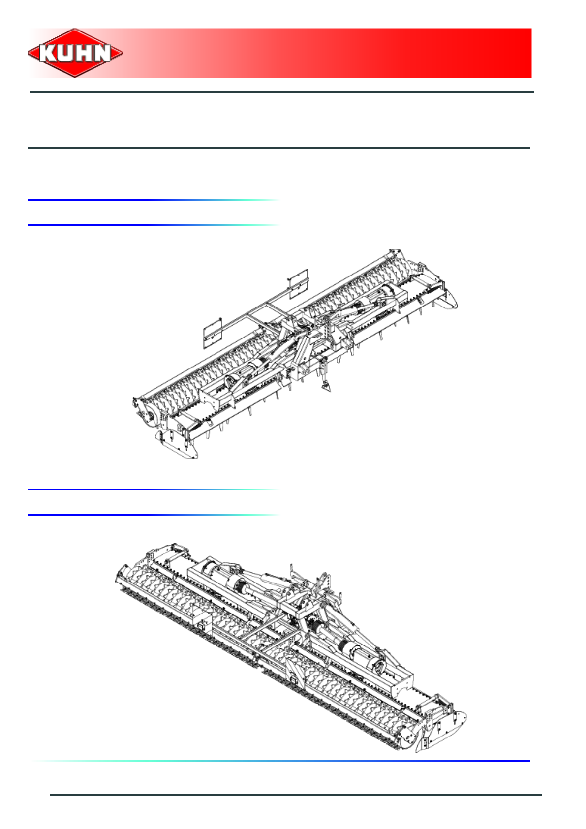
Power harrow
HR6004DR
$Dear Owner
In buying a Kuhn machine you have chosen wisely. Into it have gone years of thought, research and
improvement. You will find, as have thousands of owners all over the world, that you have the best that
engineering skill and actual field testing can produce. You have purchased a dependable machine, but only
through proper care and operation can you expect to receive the performance and long service built into it.
This manual contains all the necessary information for you to receive full efficiency from your machine. The
performance you get from this machine is largely dependent on how well you read and understand th is manual
and apply this knowledge. Please DO NOT ASSUME YOU KNOW HOW TO OPERATE AND MAINTAIN YOUR
MACHINE before reading this manual carefully. KEEP THIS MANUAL AVAILABLE FOR REFERENCE. Pass
it on to the next owner if you re-sell the machine.
Your KUHN dealer can offer a complete line of genuine KUHN service parts. These parts ar e manufactured and
carefully inspected in the same factory that builds the machine to assure high quality and accurate fitting of any
necessary replacements.
About improvements
We are continually striving to improve our products. It therefore reserves the right to make improvements or
changes when it becomes practical to do so, without incurring any obligations to make changes or additions to
the equipment sold previously.
Designated use of the machine
The HR6004DR power harr ow must only be used for work for which it has been designed: Se edbed preparation
on ploughed or unploughed ground.
Dear Owner
1
Page 4

Power harrow
HR6004DR
$Contents
Dear Owner.....................................................................................................................1
Contents..........................................................................................................................2
Identification of the machine.........................................................................................4
Front view (working position) .........................................................................................................4
Rear view (working position)...........................................................................................................4
Model identification plate ................................................................................................................5
Optional equipment..........................................................................................................................6
Safety...............................................................................................................................7
Description of symbols used in this document.............................................................................7
Safety instructions...........................................................................................................................8
Location and description of safety decals on the machine .......................................................19
Road safety equipment and recommendations...........................................................................22
Machine specifications................................................................................................24
Description and glossary...............................................................................................................24
Technical specifications................................................................................................................25
Required equipment.......................................................................................................................26
Sound levels ......... ... ... .... ... ... ... .... ............................................. ......................................................28
Putting into service......................................................................................................29
Coupling and uncoupling..............................................................................................................29
Instructions for transport............................................................................................44
2
Putting the machine into transport position................................................................................44
Conformity with the road regulations...........................................................................................45
Contents
Page 5

Power harrow
HR6004DR
Instructions for work...................................................................................................46
Putting the machine into work position............. ..........................................................................46
Adjustments in working position..................................................................................................47
Machine use....................................................................................................................................49
Optional equipment.....................................................................................................51
Set of gearwheels...........................................................................................................................51
Hydraulic lift linkage......................................................................................................................52
Track eradicators............................................................................................................................56
Front and rear levelling bar...........................................................................................................58
Rollers.............................................................................................................................................59
Maintenance and storage............................................................................................ 62
Cleaning the machine....................................................................................................................63
Lubrication............................................................................................ ..........................................64
Maintenance....................................................................................................................................71
Storage............................................................................................................................................81
T rouble shooting guide...............................................................................................82
Appendix ......................................................................................................................84
Calculating the load on an axle.....................................................................................................84
Limited warranty..........................................................................................................90
Contents
3
Page 6
$Identification of the machine
1. Front view (working position)
Power harrow
HR6004DR
2. Rear view (working position)
4
Identification of the machine
Page 7

3. Model identification plate
Please write below the type and serial number of the
machine. This information is to be indicated to the dealer
for all spare parts orders.
Power harrow
HR6004DR
Type: HR6004DR
Serial no.:
Identification of the machine
5
Page 8

4. Optional equipment
Tick box corresponding to the equipment fitted on your
machine:
Kit no. 123742 0 : Set of gearwheels (19 and 26 teeth matching gears).
Kit no. 123765 0 : Set of gearwheels (17 and 28 teeth matching gears).
Kit no. 123838 0 : Rear hydraulic lift linkage.
Kit no. 123887 0 : Track eradicator mounting yokes.
Kit no. 121661 0 : 2 track eradicators with traction bolt overload mechanism.
Kit no. 121662 0 : 2 track eradicators with spring overload mechanism.
Kit no. 123837 0 : Front or rear levelling bar.
Power harrow
HR6004DR
Kit no. 123842 0 : Maxipacker roller.
Kit no. 120915 0 : Maxicrumbler roller.
Kit no. 123701 0 : Packer roller.
6
Identification of the machine
Page 9

$Safety
1. Description of symbols used in this document
This symbol indicates a potentially hazardous situation
that if not avoided, could result in serious bodily injury.
Power harrow
HR6004DR
This symbol is used to identify special instructions or
procedures which, if not followed strictly, could result in
machinery damage.
This symbol is used to communicate technical
information of particular interest.
Safety
7
Page 10

Power harrow
HR6004DR
2. Safety instructions
Introduction
The machine must only be operated, maintained and repaired by competent persons who are familiar with
machines' specifications and operation and aware of safety regulations for preventing accidents.
The operator must imperatively respect safety instructions in this manual and in the warnings posted on the
machine. The operator is also obliged to respect curren t legislation concerning accident prevention, wor k safety
and public traffic circulation.
Designated use of the machine also means following operation, maintenance and repair recommendations
given by the manufacturer, and using o nly ge nuine spa re parts, e qu ipme nt an d accessori es, as reco mme nde d
by the manufacturer.
The manufacturer is not held liable for any damage resulting from machine applications other than those
specified by the manufacturer. Any use other than the designated operation is at the risk and responsibility of
the operator.
The manufacturer is not held liable for any damage or accident resulting from ma chine modifications carried out
by the operator himself or by a third party without previous written agreement from the manufacturer.
Read and follow the safety instructions
Before using the machine, carefully read all the safety
instructions in this manual and the warnings placed on
the machine.
Before starting work, the operator must be familiar with
all machine controls, handling devices and their
functions. It is too late to learn once work has been
started!
Never let anyone operate the machine who is not trained
to do so.
Should you have any difficulties in understanding certain
parts in this manual, please contact your KUHN dealer.
Precautions to be taken before carrying out
any operations on the machine
Before leaving the tractor or before adjusting,
maintaining or repairing the machine, disengage the
PTO drive, turn off the engine, remove ignition key and
wait until all moving parts have come to a complete stop
and apply park brake.
8
Safety
Page 11
Precautions to take before using the machine
Do not wear loose clothing which could become caught
up in moving parts.
Wear the appropriate protective clothing for the work in
hand (gloves, shoes, goggles, helmet, ear defenders,
etc.).
Ensure that all operating controls (ropes, cables, rods,
etc) are placed so as they cannot be operated
unintentionally and cause damage or injury.
Before operating the machine, check tightness of nuts
and bolts, particularly on fixing elements (tines, forks,
blades, knives, etc). Retighten if necessary.
Before operating the machine, ensure that all the safety
guards are firmly in place and in good condition.
Immediately replace any worn or damaged guard.
Power harrow
HR6004DR
Precautions when driving
Tractor handling, stability, performance and braking
efficiency are all affected by weight distribution, trailed or
mounted implements, additional ballast and driving
conditions. It is therefore of great importance that the
operator exercises caution in every given situation.
Groundspeed must be adapted to ground conditions as
well as to roads and paths. Always avoid abrupt changes
of direction.
Be particularly cautious when turning corners, paying
attention to machine overhang, length, height and
weight.
Never use a narrow track tractor on very uneven or
steeply sloping ground.
Never leave the tractor seat while the machine is
operating.
Carrying people or animals on the machine when
working or in transport is strictly forbidden.
Safety
9
Page 12

Precautions when driving on public roads
Dimensions
Depending on the dimensions of the machine, contact
the relevant authorities to ensure that it can be legally
transported on public roads.
If the machine is over the maximum legal size, follow the
local regulations for special transportation of oversize
equipment.
Transport position
Before transporting the machine on public roads, place
the machine into its transport position, according to the
instructions in this manual.
Lights and indicators
Before transporting the machine on public roads, ensure
that all legally required lightings and signallings are in
place.
Ensure that lightings and signallings are clean and in
good working order. Replace any missing or broken
equipment.
Power harrow
HR6004DR
Always obey current regulations for driving
on roads.
Gross weight and weight per axle
The drawings are not legally binding, their only aim is to illustrate the method to use.
Prior to driving on public roads, check that criteria a re met to be in conformity with th e countrie's
regulations:
- When coupling a tool to the front and rear 3-point lift linkage, the maximum authorized
payload must not be exceeded.
- When coupling tools to the front and rear 3-point lift linkages, the maximum load on each
axle's tires must not be exceeded.
- The load on the tractor front axle must always represent 20 % of the tracto r unladen weight.
For machines with hoppers or tanks:
- If the total unit weight exceeds the tractor Gross Combined Weight Rating in accordance
with the countrie's legislation, empty the hopper to travel on public roads.
- In any case, we recommend to travel on public roads with empty hoppers and tanks.
10
Safety
Page 13
Power harrow
HR6004DR
Description of symbols
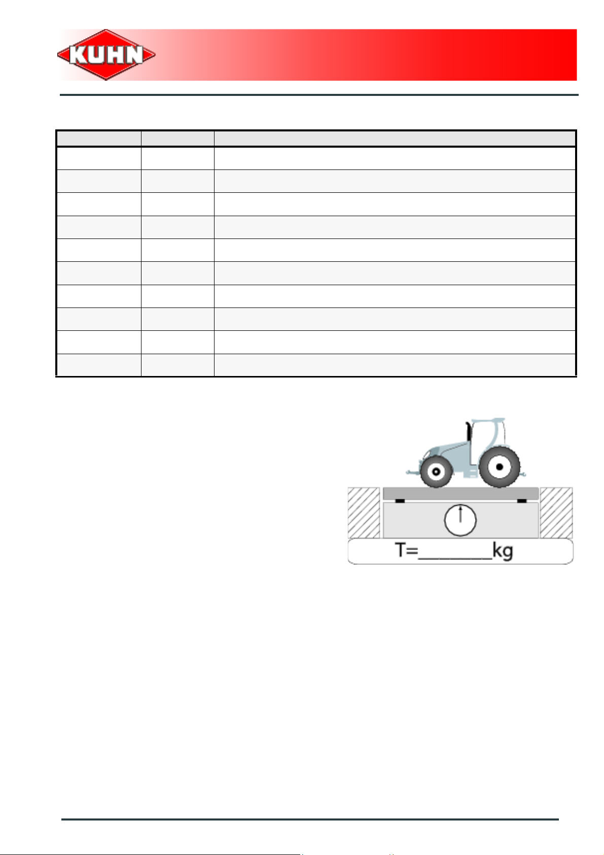
Description Units Description
T kg Tractor unladen weight
PTAC kg Gross Combined Weight Rating
T1 kg Unladen load on tractor front axle
T2 kg Empty load on tractor rear axle
t kg Axle loads (Tractor + machine)
t1 kg Load on front axle (Tractor + machine)
t2 kg Load on rear axle (Tractor + machine)
t1 max kg Maximum load authorized on the tractor front axle according to the tires
t2 max kg Maximum load authorized on the tractor rear axle according to the tires
M1 kg Total weight of front tool or front ballast
Stage 1:
To measure:
- Tractor tare (T).
Safety
11
Page 14
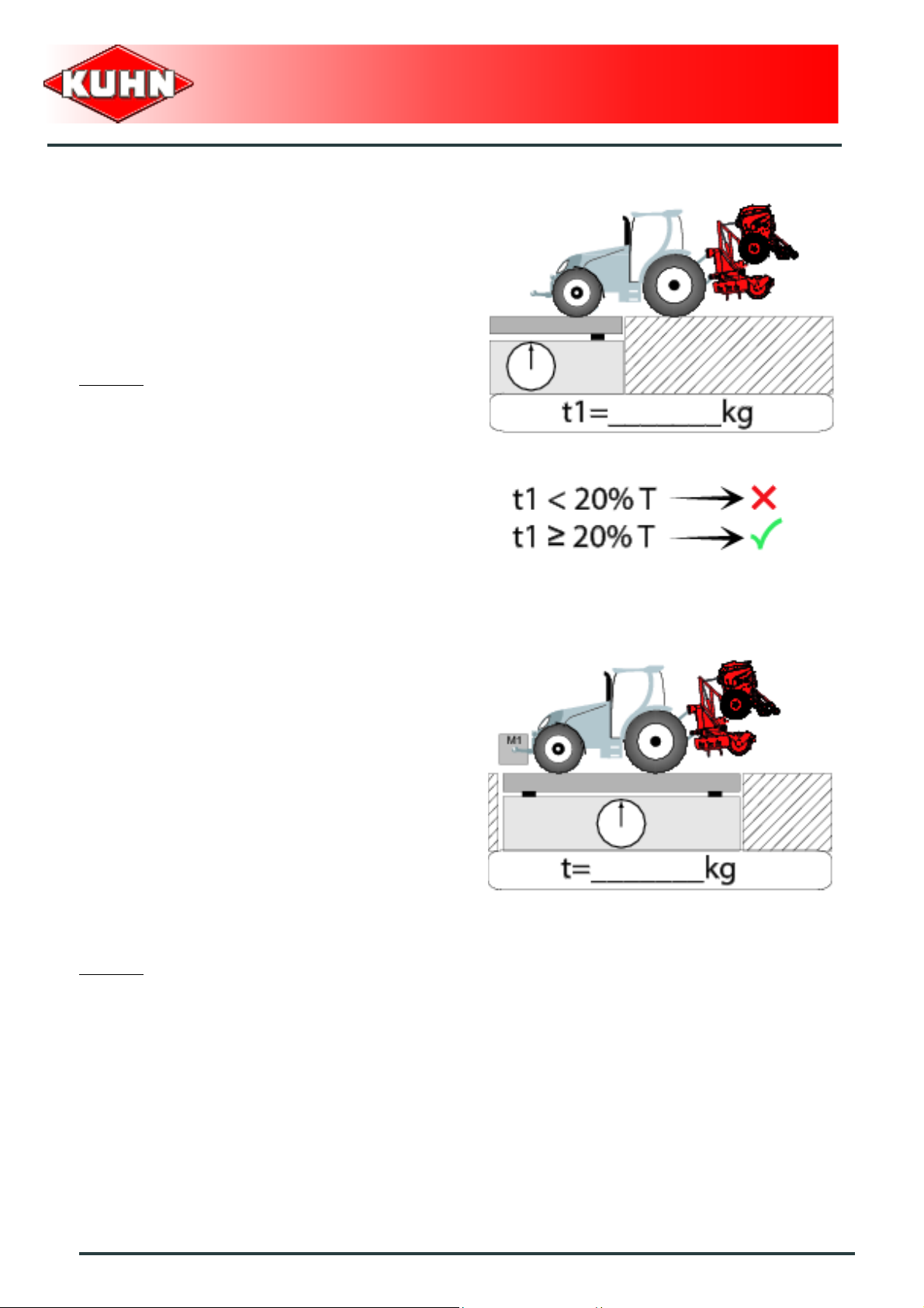
Stage 2:
- Couple the machine to the tractor.
To measure:
- Load on front axle (t1):
• Tractor + machine (transport position).
To do:
- If the front axle load (t1) is below 20% of the tractor
tare (T), add ballast weights (M1) to exceed the
minimum load on the front axle.
Example:
• (T) = 7500 kg (16535 lb)
• The front axle load must be of minimum 1500 kg
(3300 lb).(20% of T)
• (t1) = 700 kg (1545 lb).
• 700 kg (1545 lb) < 1500 kg (3300 lb).
• Add ballast weights until the minimum front axle
load is exceeded.
• Repeat checking procedure.
Power harrow
HR6004DR
Stage 3:
To measure:
- Total weight (t):
• Tractor + machine (transport position).
• Ballast weights.
Checking:
- To go to the next stage:
• Check in the tractor's operator's manual that the
value measured is below the tractor's Gross
Combined Weight Rating.
To do:
- If t < PTAC go to the next stage.
- If the total unit weight exceeds the tractor Gross
Combined Weight Rating in accordance with the
countrie's legislation, empty the hopper to travel on
public roads.
Example:
• (t) = 10000 kg (24250 lb)
• PTAC = 13000 kg .
• t < PTAC : Go to the next stage.
12
Safety
Page 15
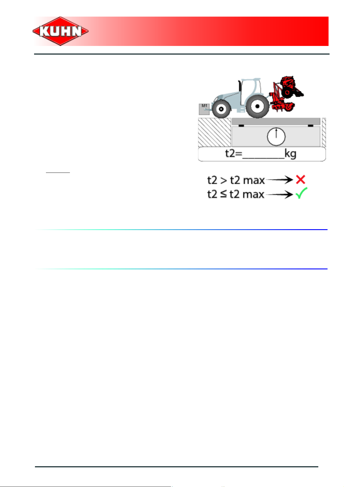
Stage 4:
To measure:
- Load on rear axle (t2):
• Tractor + machine (transport position).
• Ballast weights.
Checking:
- Check in the tractor's operator's manual that the value
measured is below the maximum allowed tractor rear
axle load.
- Check that tyre and rim specifiations are in conformity
with the requirements of the tractor manufacturer.
Example:
• Load on rear axle (t2) = 8500 kg (18740 lb)
• Check in the tractor's operator's manual that the
value measured is below the maximum allowed
tractor rear axle load.
• Check that tyre and rim specifiations are in
conformity with the requirements of the tractor
manufacturer.
Power harrow
HR6004DR
Maximum speed
Always keep to the legal speed limit for driving a tractormachine assembly on public roads.
Safety
13
Page 16
Precautions when coupling
Before attaching the machine, make sure that it cannot
accidentally start moving (chock the wheels) and that the
parking stand is in the right position.
The machine must only be attached to the hitch points
provided for this purpose.
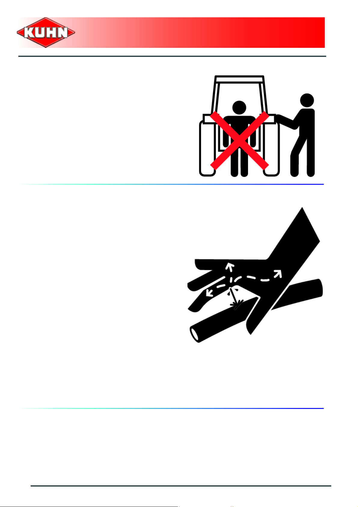
Never stand between the tractor and the machine when
operating the three point linkage.
Do not stand between the tractor and the machine
without ensuring that the parking brake is applied.
Hydraulic circuit
Power harrow
HR6004DR
Caution! The hydraulic circuit is under high pressure.
Maximum pressure at work: 200 bar.
Before connecting hoses to the tractor hydraulics,
ensure that tractor and machine circuits are not under
pressure. Before disconnecting a hose, depressurize the
hydraulic circuit.
To avoid making incorrect connections, mark hydraulic
couplers and corresponding hoses with colors.
WARNING! Functions could be reversed (for example:
lift/lower) and cause accidents.
Regularly check the hydraulic hoses. In case of normal
wear, replace the hydraulic hoses every 5 years.
Damaged or worn hoses must immediately be replaced.
When replacing the hydraulic hoses, only use hoses with
the specification recommended by the manufacturer of
the machine.
To locate a leak, use appropr iate means. Protect body
and hands from liquid under pressure.
Any liquid under pressure (particularly oil from
hydraulics) can penetrate the skin and cause severe
injury. If injured, see a doctor immediately, there could
be danger of infection.
Before any adjustments, maintenance or repairs are
carried out, lower the machine to the ground,
depressurize the hydraulics, turn off the engine, remove
ignition key and wait until all moving parts have come to
a complete stop.
14
Safety
Page 17

PTO shaft
Use only PTO shafts supplied with the machine or
recommended by the manufacturer.
The protective shield of the tractor PTO stub, the PTO
shaft guards and the protective covering of the machine
input shaft must always be in place and in good
condition.
Make sure that the PTO shaft guards are se cured with
the safety chains provided.
Any worn or damaged guards must be replaced
immediately. A worn guard or an unprotected PTO shaft
can cause a serious or even a lethal accident.
Do not wear loose clothing that could be caught in the
rotating PTO shaft.
Before attaching or removing a PTO shaft, or before
doing any work on the machine, disengage the PTO
drive, turn off the engine, remove ignition key and wait
for all moving parts have come to a complete stop.
If the primary PTO shaft is equipped with a slip clutch or
a free wheel, these must be fitted on the machine side.
Ensure that the PTO shaft is always correctly fitted and
locked into place.
Before connecting the PTO shaft, ensure that the PTO
speed (rotational frequency) and directions of rotation
are in line with manufacturer's recommendations.
Before engaging the PTO drive, make sure all people
and animals are clear from the machine. Never engage
the PTO drive when the tractor engine is stopped.
When uncoupling the machine, rest the PTO shaft on the
support specially provided, and replace protective cover
on the PTO stub of the tractor.
Read and follow the instructions in the operator's ma nual
provided with the PTO shaft.
Power harrow
HR6004DR
Safety
15
Page 18

Precautions during manoeuvres
When moving the machine from the transport positio n to
the working position and vice versa, make sure that
nobody is within the machine pivoting area.
Remote controlled components
Danger of crushing and shearing can exist when
components are operated by hydraulic or pneumatic
controls. Keep away from these danger zones.
Safety decals
Safety warning decals are placed in pictorial form on
various parts of the machine. They are ther e to warn you
of potential dangers and to tell you how to avoid
accidents. Always keep the safety decals clean and
readable, and replace them when they are worn,
damaged, missing or illegible.
Power harrow
HR6004DR
Waste disposal
Respect the environment! Never spill pollutants (oil,
grease, filters, etc.) on the ground, never pour them
down the drain and never discard them in any other
place where they could pollute the environment. Never
throw away or burn a tyre. Always take waste to
specialized recycling or waste disposal centers.
16
Safety
Page 19

Precautions for maintenance and repair work
Before leaving the tractor or before adjusting,
maintaining or repairing the machine, disengage the
PTO drive, turn off the engine, remove ignition key and
wait until all moving parts have come to a complete stop
and apply park brake.
Rest the machine on the ground, release the pressure
from the hydraulic circuit and leave the machine to cool
down.
Make sure that the parts of the machine that need to be
lifted for maintenance or repair work are firmly propped
up.
Before any work is done on the electric circuit or before
any electric welding is carried out on the attached
machine, disconnect the machine from the tractor
electrical circuit. Also disconnect alternator and battery
terminals.
Repairs on elements under pressure or tension (springs,
pressure accumulators, etc.) must only be carried out by
competent persons with regulation equipment.
Wear the appropriate protective clothing for the work in
hand (gloves, shoes, goggles, helmet, ear defenders,
etc.).
Do not solder, weld or use a blow torch near fluids under
pressure or inflammable products.
For your own safety and for correct machine operation,
only use original manufacturer parts.
It is strongly recommended to have your machine
checked by your Kuhn dealer after each season,
especially tools and their attaching hardware.
Power harrow
HR6004DR
Safety
17
Page 20

Projection of stones and foreign objects
For driver safety, always use a tractor equipped with a
cab. Never start the machine when there are people
nearby. Even when the machine is used in accordance
with its purpose, objects may be projected. Stones and
other foreign objects projected by the moving parts can
travel a considerable distance. Keep all persons and
animals away from the danger zone.
Precautions for machine use
Power harrow
HR6004DR
After each use, check the tools (blades) and their
attachment hardware in accordance with the instructions
given in the present manual.
Check the guards regularly. Immediately replace any
damaged or missing elements.
Make sure all the guards are in place. Keep all persons
and animals away from the danger zone.
Stay a safe distance from the machine when the cutting
tools are in movement.
Never work in reverse.
After disengaging the PTO drive, tools can continue
rotating for some time. Stay away from the machine until
all moving parts have come to a complete standstill.
If an obstacle is hit, disengage the PTO drive, stop the
tractor engine, remove the ignition key and wait for all
moving parts to come to a complete standstill. Check the
entire machine for any damage before resuming work.
It is strictly forbidden to store the machine in folded
position. For long parking periods, even when attached
to the tractor, the machine must be unfolded with both
half-harrows resting on the ground.
Never engage the tractor PTO drive when the machine
is in transport position.
18
Safety
Page 21
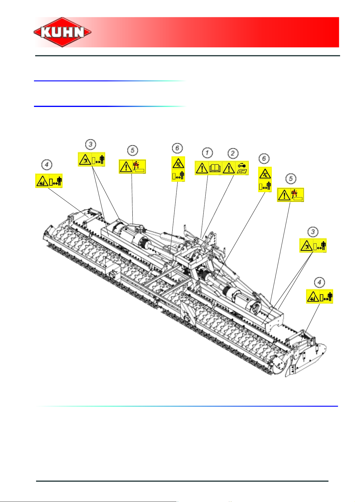
3. Location and description of safety decals on the machine
Location of safety decals
Power harrow
HR6004DR
Safety
19
Page 22
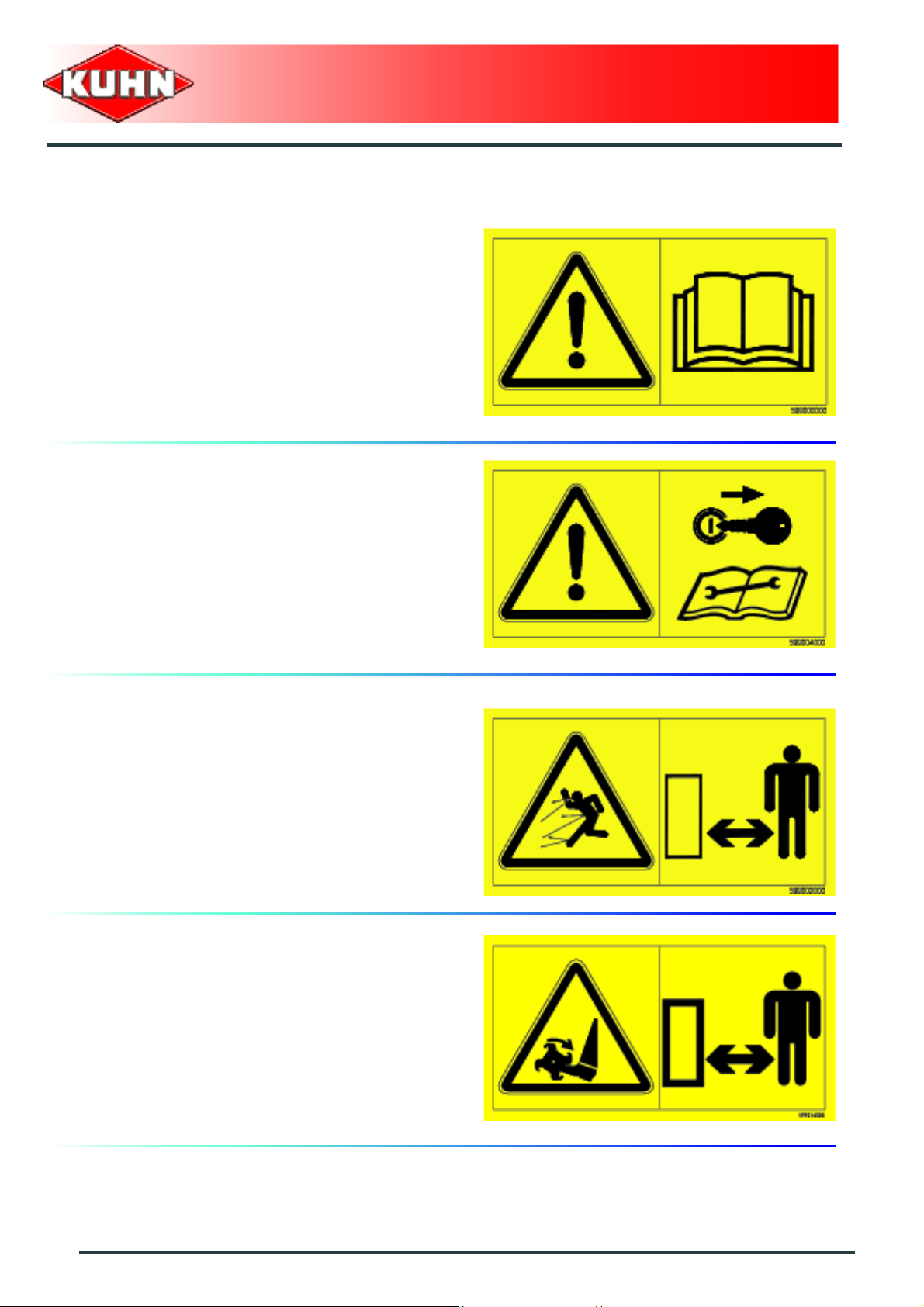
Description of safety decals
Operating instructions (1)
The operators' manual contains all the information
necessary for using the machine safely. It is imperative
to read and comply with all instructions.
Working on the machine (2)
Before leaving the tractor or before adjusting,
maintaining or repairing the machine, disengage the
PTO drive, turn off the engine, remove ignition key and
wait until all moving parts have come to a complete stop
and apply park brake.
Power harrow
HR6004DR
Projections (3)
Stones and other debris pro jected by the moving parts
can travel a long distance. Always stay at a safe distance
from the machine.
Rotary tools (4)
Keep away from rotating elements and from the machine
all the time the engine is running, the PTO drive is
engaged and the rotors are turning.
20
Safety
Page 23
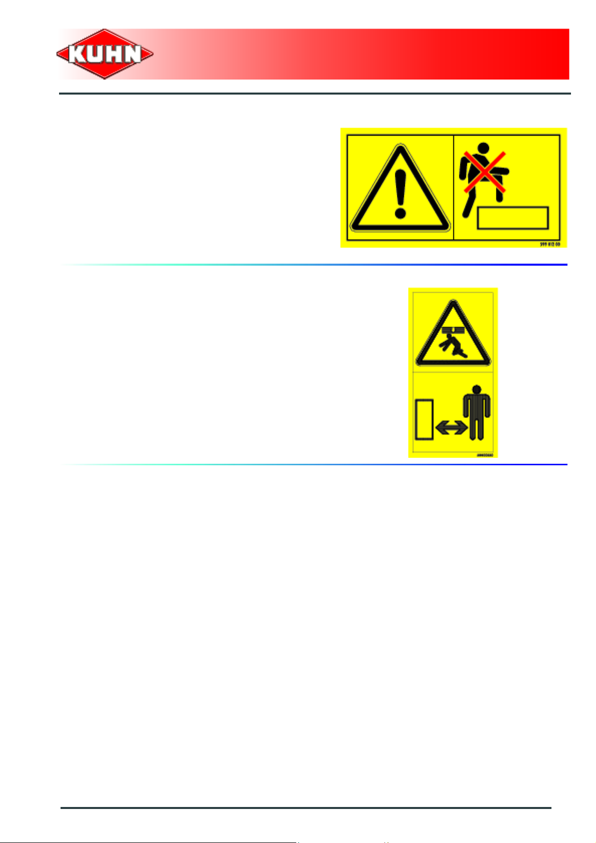
Do not step on the machine (5)
Do not step on the machine: Risk of falling or damaging
the protection device.
Body crushing (6)
Stay a safe distance from the machine. Crushing hazard.
Power harrow
HR6004DR
Safety
21
Page 24
4. Road safety equipment and recommendations
The road safety equipment is mounted in the factory or
by your authorized Kuhn dealer according to current
safety regulations. Always keep to the legal speed limit
for driving a tractor-machine assembly on public roads.
Whatever the speed, we recommend, for everyones'
safety, not to exceed a maximum speed of 25 km/h
(15.5 mph).
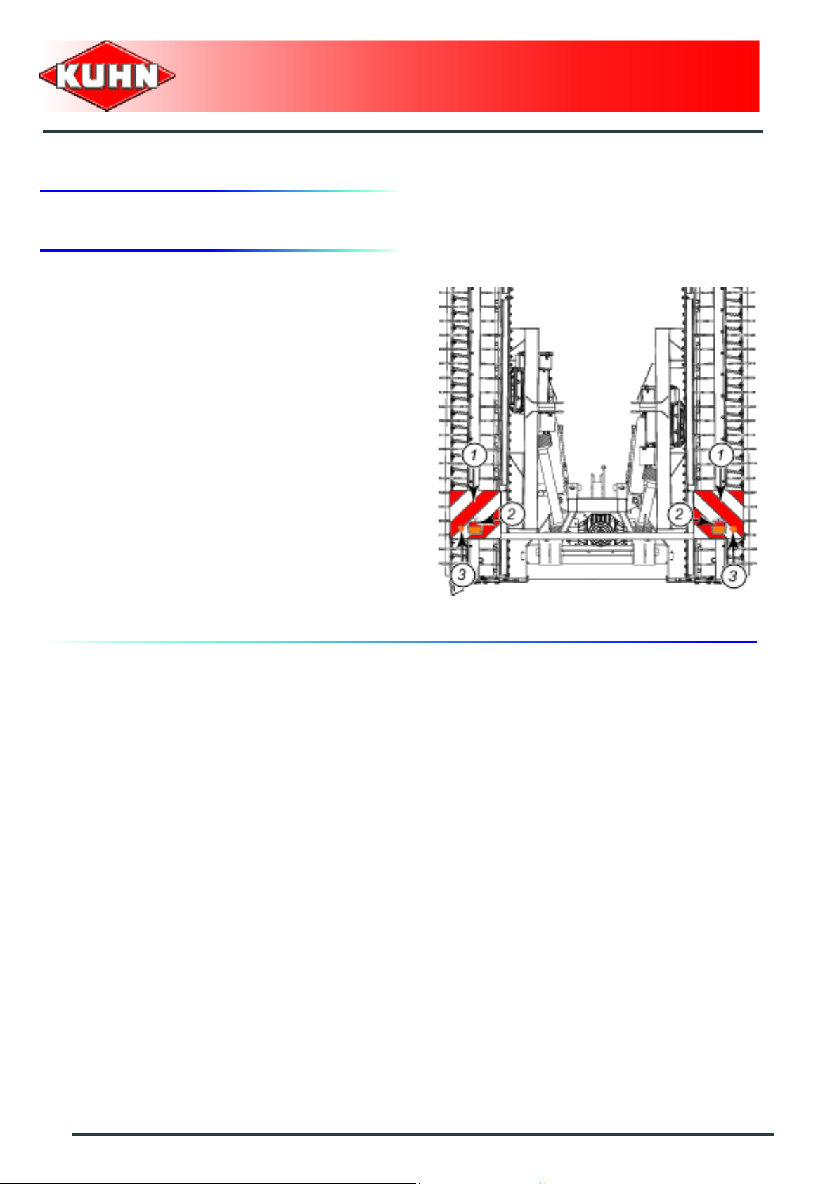
The rear safety device comprises:
- 2 signalling panels (1).
- 2 signalling lights (2) (red light / stop light / turn signal
light).
- 2 red reflectors (3).
Power harrow
HR6004DR
22
Safety
Page 25
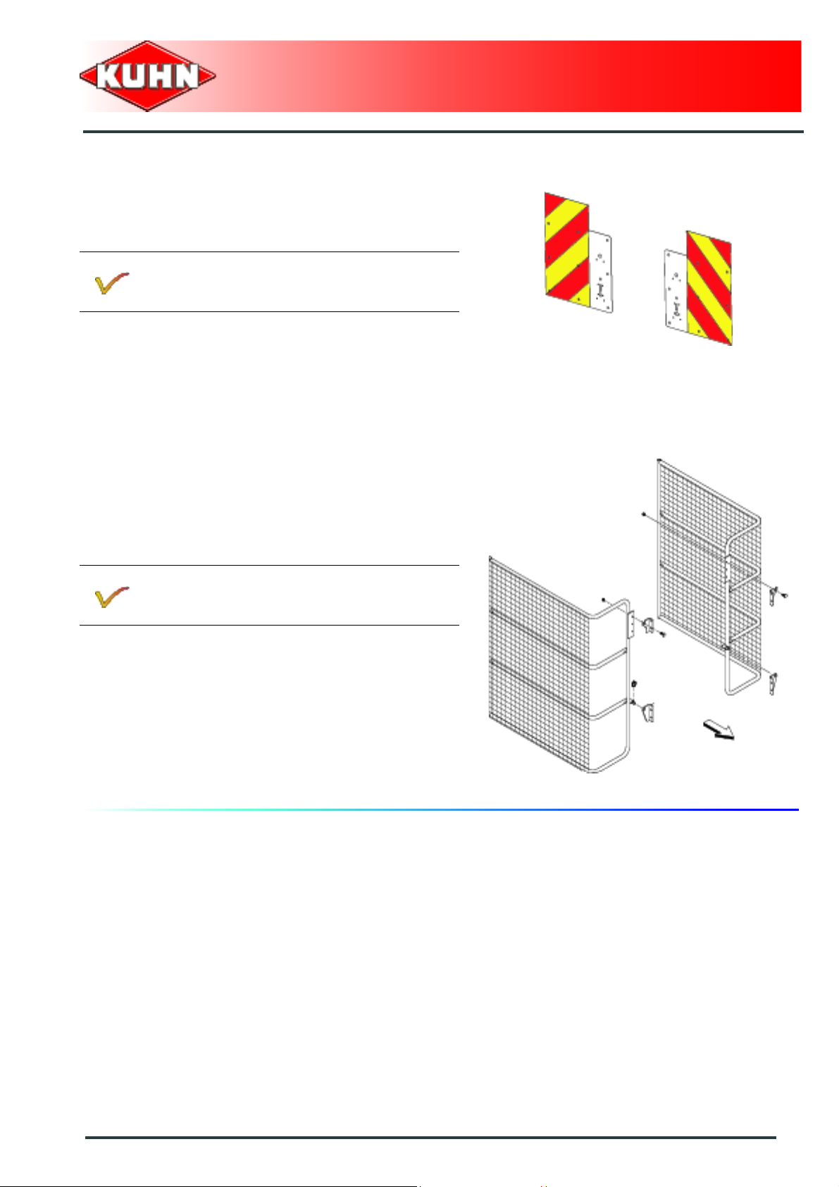
Instructions specific to Italy
The machine can be fitted with specific signalling lights
to comply with the road regulations.
Signalling kit Italy: Kit no. 1238390.
Power harrow
HR6004DR
The machine must be fitted with specific safety screens
to comply with the current legislation.
Safety screens: Kit no. 1238960.
Safety
23
Page 26
$Machine specifications
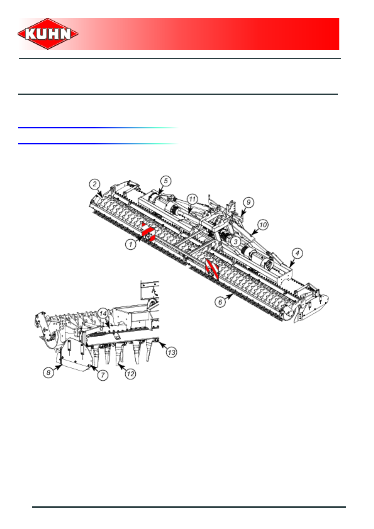
1. Description and glossary
0
Power harrow
HR6004DR
1 :
Lights and indicators
3 :
Central gearbox
5 :
Side gearbox
7 :
Side deflector
9 :
Lock
11 :
Intermediate PTO shaft 2
13 :
24
Machine specifications
Blade holder
2 :
4 :
6 :
8 :
10 :
12 :
14 :
Roller
Half-harrow
Scraper bar
Anti-ridging plate
Lift cylinder
Blade
Trough
Page 27

Power harrow
HR6004DR
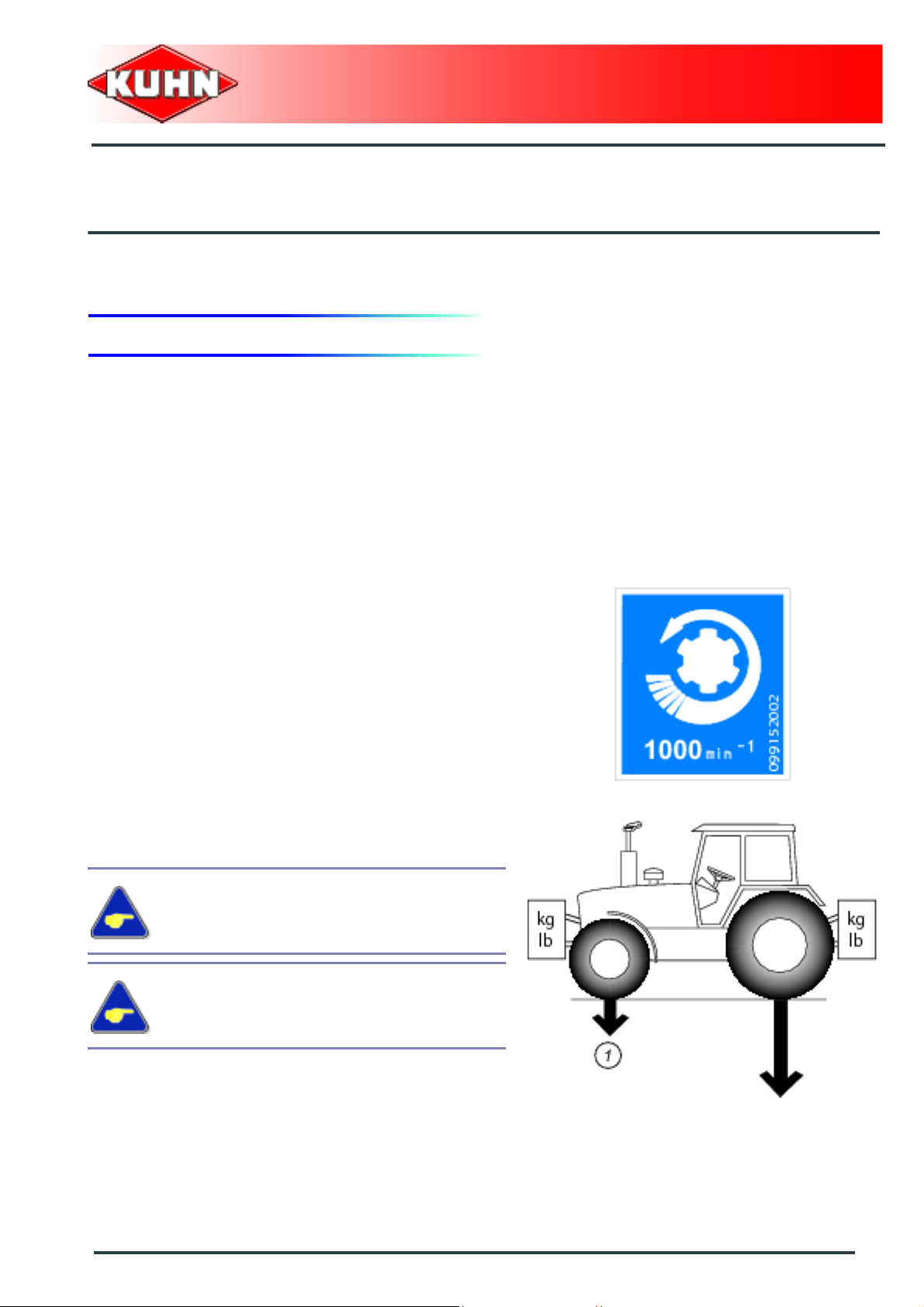
2. Technical specifications
HR6004DR
Coupling device Category 3
PTO speed 1000 min
Number of rotors 20
Number of blades right / left 20 / 20
Working width (DIN11220) 6.00 m (19’8’’) (approximately)
Working depth from 3 to 25 cm (1.18’’ - 10’’) (approximately)
Width in working position 6.21 m (20’4’’)
-1
Width in transport position
Height in transport position 3.60 m (11’10’’)
DIN engine power requirement 110 kW (150 hp)
Maximum allowable DIN engine power 206 kW (280 hp)
Weight:
- With Maxicrumbler rollers
- With PK2 Packer rollers
- With Maxipacker rollers
2.52 m (8’3’’) with rollers raised
2900 kg (6393 lb) (approximately)
3290 kg (7253 lb) (approximately)
3350 kg (7385 lb) (approximately)
2.70 m (8’10’’)
Machine specifications
25
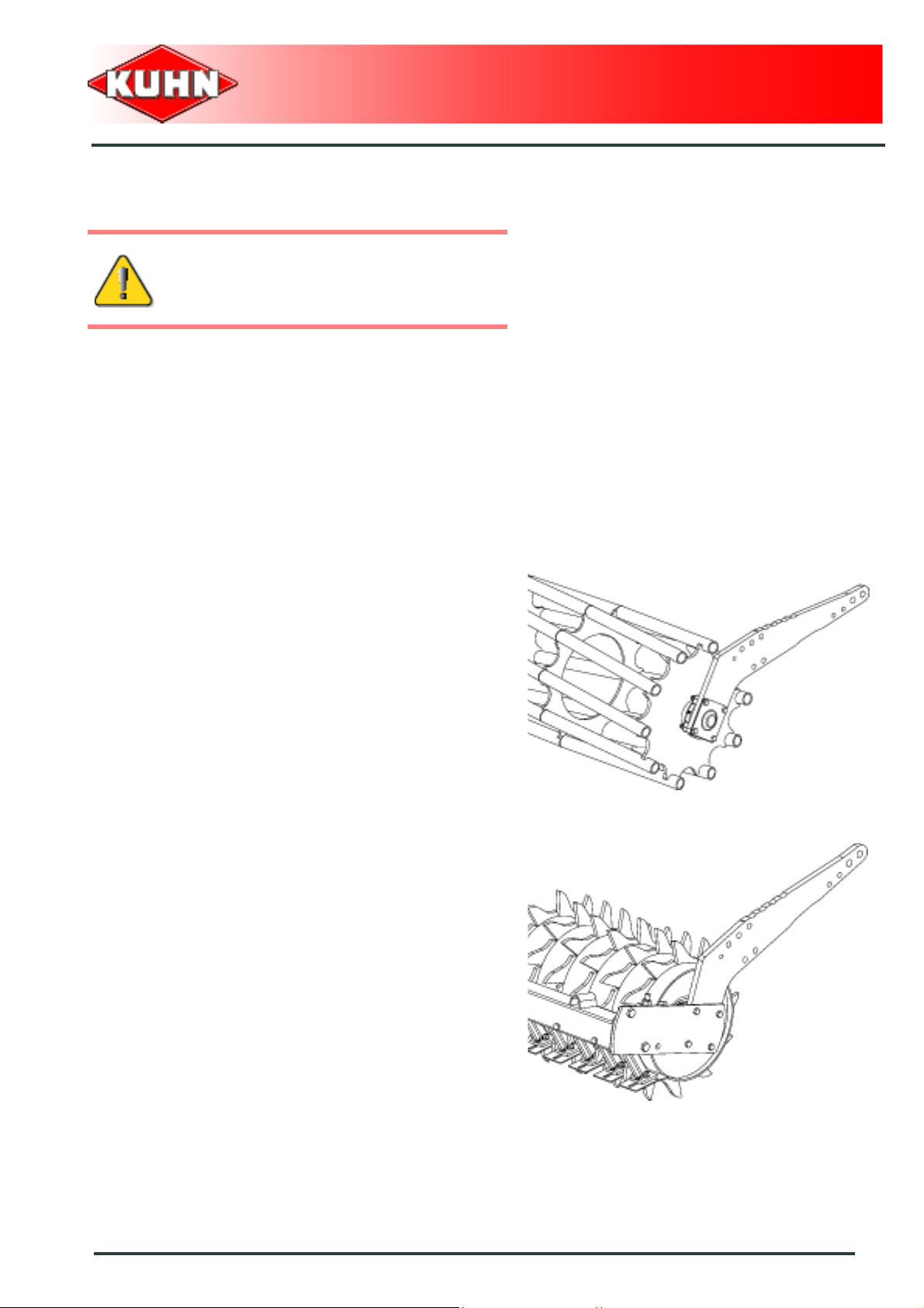
Page 28

Front soil loosening share
The front soil loosening share brakes up the strip of land
between the two half-harrows. The front soil loosening
share is fitted on the lower crossbar of the central frame.
3. Required equipment
Intermediate PTO shaft 1
The machines are factory fitted with one of the following
PTO shafts:
(Part no. 4600654)
1 3/8’’ - 21 spline pto shaft.
or
(Part no. 4600655)
1 3/4’’ - 6 spline pto shaft.
or
(Part no. 4600656)
1 3/4’’ - 20 spline pto shaft.
Power harrow
HR6004DR
Power harrow blades
The machines are factory fitted with one of the following
blades:
Part no. K2500090 and Part no. K2500100
Standard left and right blade.
or
Part no. K2501120 and Part no. K2501130
Left and right OPTIMIX blade.
or
Part no. K2500260 and Part no. K2500270
Left and right DURAKUHN blade.
26
Machine specifications
Page 29
Rollers
The roller is used as a protection device at
the rear of the machine. It must never be
removed for work.
The roller is an essential element of the harrow and has
the following 4 functions:
- Set and control the working depth.
- To pack the soil evenly behind the rotors and create
an optimum seedbed.
- To increase seedbed crumbling and clod break-up.
- To improve seedbed levelling.
The machines are factory fitted with one of the following
rollers:
Maxicrumbler roller: Part no. 1209150
The Maxicrumbler roller is adapted to dry or slightly wet
soils.
Power harrow
HR6004DR
or
Packer PK2 roller: Part no. 1237010
The Packer PK2 roller is adapted to soils which are
subject to capping or very clayey and sticky. The roller is
fitted with a scraper bar. Scraper plates are located
between the rows of studs to ensure roller cleaning.
Machine specifications
27
Page 30

or
Maxipacker roller: Part no. 1238420
The Maxipacker roller is adapted to all soil types and
particularly to wet and sticky soils. The roller is fitted with
a scraper bar. Scraper plates are located between the
rows of studs to ensure roller cleaning.
Power harrow
HR6004DR
4. Sound levels
Sound levels have been measured in accordance with the measuring methods as defined in:
NF EN ISO 4254-1 «Agricultural machinery - Safety - Part 1: General requirements»
Weighted equivalent continuous acoustic pressure level at the driver's seat (closed cabin) L (A) eq:
Tractor only: 78.7 dB(A)
Tractor + machine: 77.3 dB(A)
28
Machine specifications
Page 31
$Putting into service
1. Coupling and uncoupling
Description of coupling elements
- 2 hitch pins diameter 37 mm (1.45’’) for the lower link
arms.
- A top link hitch pin diameter 31 mm (1.22’’).
- A PTO shaft.
- 2 hydraulic hoses pressurizing the half-harrow lift
cylinders.
- A 7-pin plug.
- A release cord.
Power harrow
HR6004DR
Preparing the tractor
The machine adapts to tractors fitted with a 3 point
linkage category 3.
The tractor nominal PTO speed must be 1000 min
The tractor must be fitted with a double acting hydraulic
outlet.
The tractor must be fitted with lower link
stabilizers.
The front axle load (1) must never, under any
circumstances, be less than 20% of the
tractor's unladen weight.
-1
.
Putting into service
29
Page 32
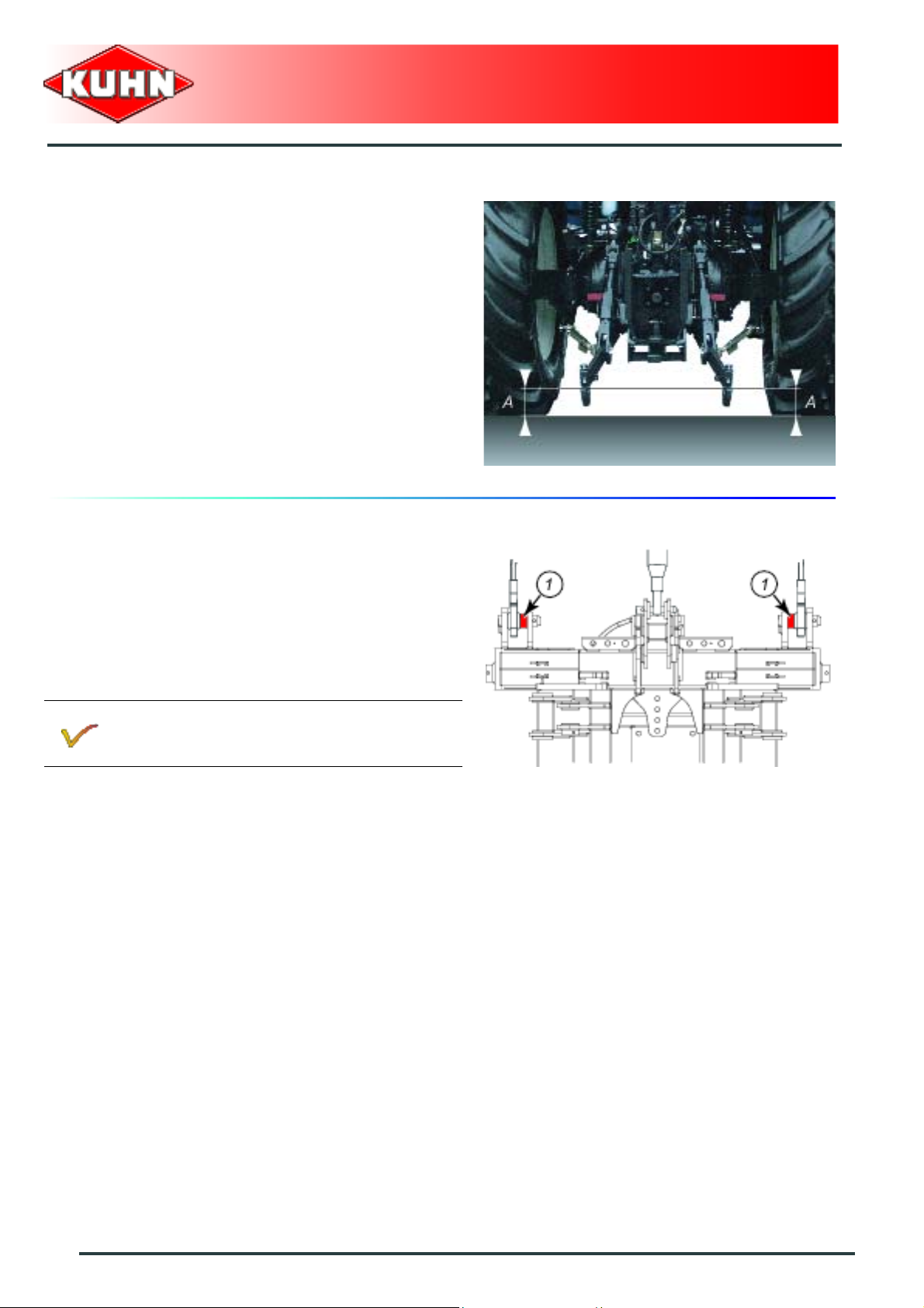
Parallelism of lower linkage arms
Adjust tractor lift rods so that lower linkage arms are at
equal height from ground.
Power harrow
HR6004DR
Coupling the machine
- Remove the lower hitch pins.
- Position tractor lower links inside machine attachment
yokes.
- Position ball joints of tractor lower links in line with
holes of machine lower yokes.
- Position bushes (1) inside frame coupling yokes.
2 bushes diameter 37 mm (1.45’’) are supplied
with the machine. Part no. K2501780
- Insert lower hitch pins and secure them with lynch
pins.
30
Putting into service
Page 33

.
- Attach top link with hitch pin.
• Use tractor and machine attachment holes to adju st
the top link position.
To obtain optimum PTO shaft angles and
tractor lift capacity, the top link must be
parallel to the lower links or slightly pointing
downwards towards the tractor.
- Insert hitch pin anti-rotation arm (1) in the machine
mounting yoke and secure with lock pin.
Power harrow
HR6004DR
Hydraulic connections
Connect the 2 hydraulic hoses of the transport/work
cylinders to a double acting valve.
Electrical connections
Connect 7-pin plug to the tractor.
Putting into service
31
Page 34

Intermediate PTO shaft 1
Make sure that the PTO shaft is correctly
adjusted, to avoid premature wear and tear.
Separate the two half PTO shafts and connect them to
the machine's input shaft and to the tractor PTO stub.
Check the length of the PTO shaft:
- Fully raise the machine:
• When the PTO shaft is in its maximum extended
position, the tube overlap must be more than
220 mm (8.6’’).
- Lower the machine in order to place PTO shaft in
horizontal position:
• When the PTO shaft is in its maximum overlap
position (retracted), tubes should not butt against
the yokes. As a safety measure, a clearance (L) of
at least 10 mm (0.39’’) must be maintained.
Power harrow
HR6004DR
If this is not the case:
Follow instructions given in the operator's
manual delivered with the PTO.
Never operate the PTO shaft at an angle X exceeding
30°.
32
Putting into service
Page 35
To avoid serious accidents, the PTO drive
shaft guards must be properly in place and
fixed with the chains provided.
Attach PTO shaft guard chain in hole (1) on machine
side.
Immediately replace any worn or damaged
guard.
Intermediate PTO shaft 2
Power harrow
HR6004DR
The machine is fitted with 2 intermediate PTO shafts 2
for driving the half harrows.
The PTO shafts are factory fitted and require no
adjustments.
The PTO shafts are factory fitted with a cam type cut-out
clutch. Check that cut-out clutches disengage during the
first periods of use:
- If the cam type cut-out clutches disengage too
frequently, the adjustment is too light. (See section:
Cam type cut-out clutch adjustment).
- If the cam type cut-out clutches do not disengage,the
adjustment is too heavy. (See section: Cam type cutout clutch adjustment).
Cam type cut-out clutch
Cam type cut-out clutches are based on the principle of
disengaging cams that release when an overload
occurs. When the cut-out clutch releases, it cuts-out
torque transmission to the machine.
When the cam type cut-out clutch releases:
- Disengage tractor PTO.
- Lift the machine off the ground.
- Engage the tractor PTO.
The cam type cut-out clutches re-engage
automatically.
Putting into service
33
Page 36

Power harrow
HR6004DR
If a foreign object gets caught in the machine:
Before carrying out any maintenance or repairs on the machine, switch off the tractor
engine, remove ignition key, wait until all moving parts have come to a standstill and
apply park brake.
Remove foreign body.
Check that no working parts have been damaged.
Engage the tractor PTO.
The cam type cut-out clutches re-engage automatically.
Do not re-engage cut-out clutches by simply reducing the PTO speed (rotational
frequency). This could cause premature wear of the cut-out clutch cams due to friction
between the cams and their housings.
Fitting the cam type cut-out cluch.
Fitting of the cam type cut-out clutches to the side
gearbox drive shafts is effected by a clamp cone which
locates in the drive shaft attachment groove.
Cam type cut-out clutch removal.
- Uncouple PTO shaft on lateral gearbox side.
- remove cam type cut-out clutch guard.
- Loosen clamp cone by unscrewing the cone a few
turns.
- Using a punch diameter 10 mm (0.4’’), free clamp
cone from its seat.
- Fully remove clamp cone.
- Remove cam type cut-out clutch from input sh aft.
34
Putting into service
Page 37

Fitting the cam type cut-out clutch.
Regularly check that there is no play between
the cam type cut-out clutches and their
shafts.
With the clamp cone disassembled:
- Slide cam type cut-out clutch on shaft and align clam p
cone housing with the shaft circular groove.
- Screw the clamp cone in within its housing while at the
same time applying a slight alternate axial movement
so that the clamp cone takes th e right position in the
circular groove.
- Torque at 7 daN m (51 lbf ft).
- Reinstall cam type cut-out clutch guard.
Cam type cut-out clutch adjustment:
Power harrow
HR6004DR
Adjust cam type cut-out clutches to suit tractor
power.
Never exceed the maximum allowable DIN
engine power: 206 kW (280 hp).
Altering the setting:
Before disassembling, check that the cam type cut-out
clutches are engaged.
Remove cam type cut-out clutch from input shaft.
Using a screwdriver:
- Remove seal (1).
Remove circlip (2).
Remove the hub assembly:
- Disengage cams (3) taking note of their position.
- Remove spring cartridge (4).
Putting into service
35
Page 38

Spring cartridge adjustment:
- Measure dimension L (Using a vernier caliper).
- Note : On first removal of the slip clutch, use Graph
below to determine measurement L. The measure L
will usually be found to be between 48.9 and 49.7 mm
(1.92’’ - 1.95’’).
- Adjust measure L to the required length.
Power harrow
HR6004DR
36
Putting into service
By increasing the dimension L, the release effort
is reduced and vice versa.
Page 39

- Secure hexagonal (6 faces) he ad screw (1) of spri ng
cartridge in a vice.
- Remove roll pin (2).
- Tighten or loosen nut (3).
- Reinstall roll pin (2).
- Grease all components.
- Reinstall the assembly and make sure that the cams
are positioned correctly (4): The angled faces of the
cams must match the angled slots in the bore of the
housing.
- Reinstall the cam type cut-out clutch onto its shaft.
PTO output stub on central gearbox
The central gearbox is factory fitted with a rear PTO
output stub that rotates in the same direction and at the
same speed as the tractor PTO.
The rear PTO enables driving a complementary tool.
When using the rear PTO output stub, remove guard (1)
and fit plastic safety guard (2) (Part no. 58707010).
Power harrow
HR6004DR
The rear PTO output stub power is limited to
37 kW (50 hp).
When the rear PTO output is no longer used,
remove guard (2) and reinstall guard (1).
Putting into service
37
Page 40

Adjusting the machine
Lateral adjustment of the lower linkage arms
- Balance the play on either sides of the lift linkage and
lock lower link stabilizers.
Power harrow
HR6004DR
Front/rear machine levelling
Adjust the top link length so that the machine is
horizontal with regards to the ground.
38
Putting into service
Page 41
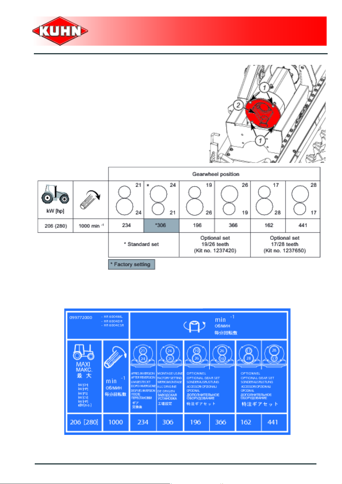
Adjusting the rotor speed.
The rotor speed can be adjusted by inverting the
standard gearwheels or by using optional gearwheel
sets.
.From the working position:
- Remove screws (1) and gearbox cover (2).
Position gearwheels according to the chart:
Power harrow
HR6004DR
Refer to the decal fitted on the machine .
Putting into service
39
Page 42

- Clean and reassemble the unit.
Check O-ring is correctly positioned within
gearbox cover.
- Tightening torque: 10 daN m (74 lbf ft).
- Proceed the same way on the other gearbox.
The rotor speed must be the same for both
half-harrows.
Adjusting the roller scrapers
Standard plate
Power harrow
HR6004DR
The scraper plates are factory preset on a reference
roller.
The scraper bar is factory fitted with:
- Packer PK2 roller: Non coated plates (Part
no. 52532130).
- Maxipacker roller: Hard coated plates (Part
no. 52593410).
When the machine is attached, check that the roller can
rotate freely.
Adjusting the plates:
• Loosen plate attachment nut.
• Adjust plate to bring it closer to the roller. Check that
roll and scraper do not contact by rotating the roller.
• Tigthen nut. Torque nut to: 8 daN m (59 lbf ft).
• Ensure the plates are fitted central to the stud rows.
• The slots in the scraper plate supports provide
lateral adjustment: Tightening torque: 10 daN m
(67 lbf ft).
Maxipacker roller:
Note the scraper plate mounting direction:
ensure that the hard coating is towards the front
and faces down: Ensure that the scraper hard
coating is towards the front and faces down.
40
Putting into service
Page 43

Nylon scraper plate
- Packer PK2 roller: Nylon scraper plate (Part
no. 52570200).
- Maxipacker roller: Nylon scraper plate (Part
no. 52592300).
The nylon scraper plate is permanently in contact with
the roller tube for cleaning it.
The nylon scraper plate is particularly well suited for
light, silty or chalky soils, or soils with small amounts of
plant residue or stones.
Fitting and adjusting the nylon scraper plate :
- Place nylon plate between 2 metallic scraper plates:
• Packer PK2 roller (Part no. 52532130).
• Maxipacker roller (Part no. 52598910).
- The nylon scraper plate must protrude the metallic
scraper plates by approximately 10 mm (0.4’’).
- The nylon plate is reversible for longer service life.
Power harrow
HR6004DR
Putting into service
41
Page 44

Adjusting the side deflector
For safety reasons, it is not allowed to fold
the side deflectors over the trough.
The vertical position of the deflector must be adjusted to:
- The working depth.
- The blade wear.
Loosen the 4 nuts (1).
Adjust side deflector (2) to the required position.
Tighten the 4 nuts (1).
Adjust both sides to the same setting.
Power harrow
HR6004DR
The longitudinal (front-rear) position of the deflector antiridging plate must be adapted to:
- The roller position and type.
Loosen the 2 nuts (1).
Set side deflector anti-ridging plate in the required
position.
Tighten the 2 nuts (1).
The anti-ridging plates must be positioned
nearest the roller, but without interference.
Adjust both sides to the same setting.
42
Putting into service
Page 45

Uncoupling the machine
Check that nobody is within the machine
pivoting area:
- If there is someone, make sure the
person moves away.
Park the machine on an even fairly level
ground.
The machine is parked when the 2 halfharrows rest on the ground.
Even when coupled, put the machine in
working position for long parking periods.
From the working position:
Power harrow
HR6004DR
When track eradicators are fitted on the
machine, they must be raised before parking
the machine.
Raise front share before parking the
machine.
- Lower the tractor three-point linkage to rest the
machine on the ground
- Disconnect the PTO shaft from the tractor.
- Secure PTO shaft into its' support (1).
- Disconnect and store hydraulic hoses on holder (2).
- Disconnect and store 7-pin plug in its holder (2).
- Detach the top link from the machine end.
- Uncouple lower linkage arms.
- Lower the tractor three-point linkage.
The machine is uncoupled.
Putting into service
43
Page 46

$Instructions for transport
Before placing the machine into transport
position:
- Wait until the rotating parts have come
to a complete stop.
- Check that nobody is within the machine
pivoting area:
• If there is someone, make sure the
person moves away.
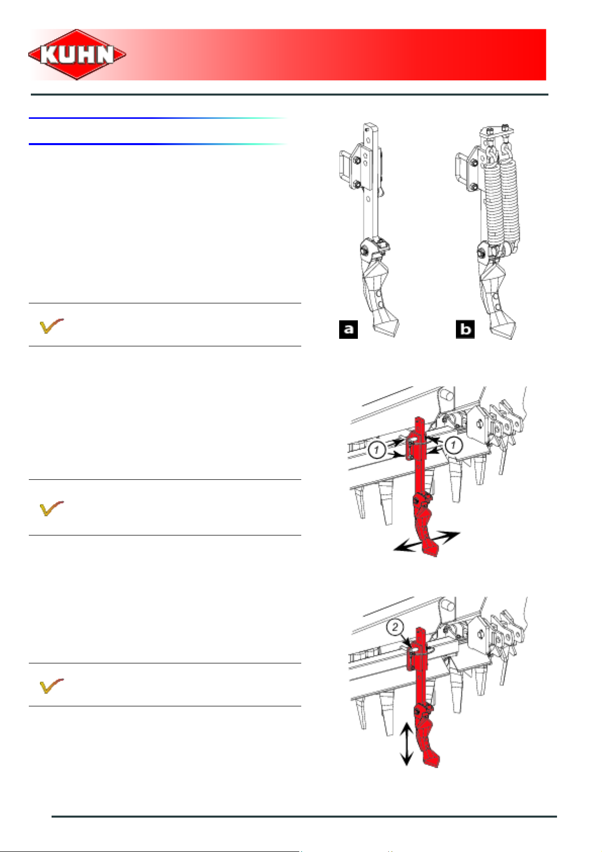
1. Putting the machine into transport position
Power harrow
HR6004DR
When optional equipment is used, follow
specific procedures mentioned in the related
section «Optional equipment».
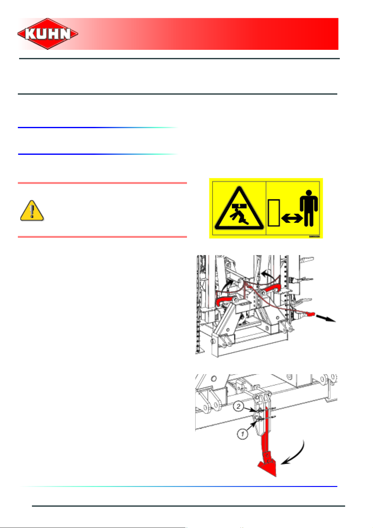
From the working position:
- Lift the machine with the tractor's three point linkage.
- Activate half-harrow lift cylinders (1) until locks (2) are
fully engaged.
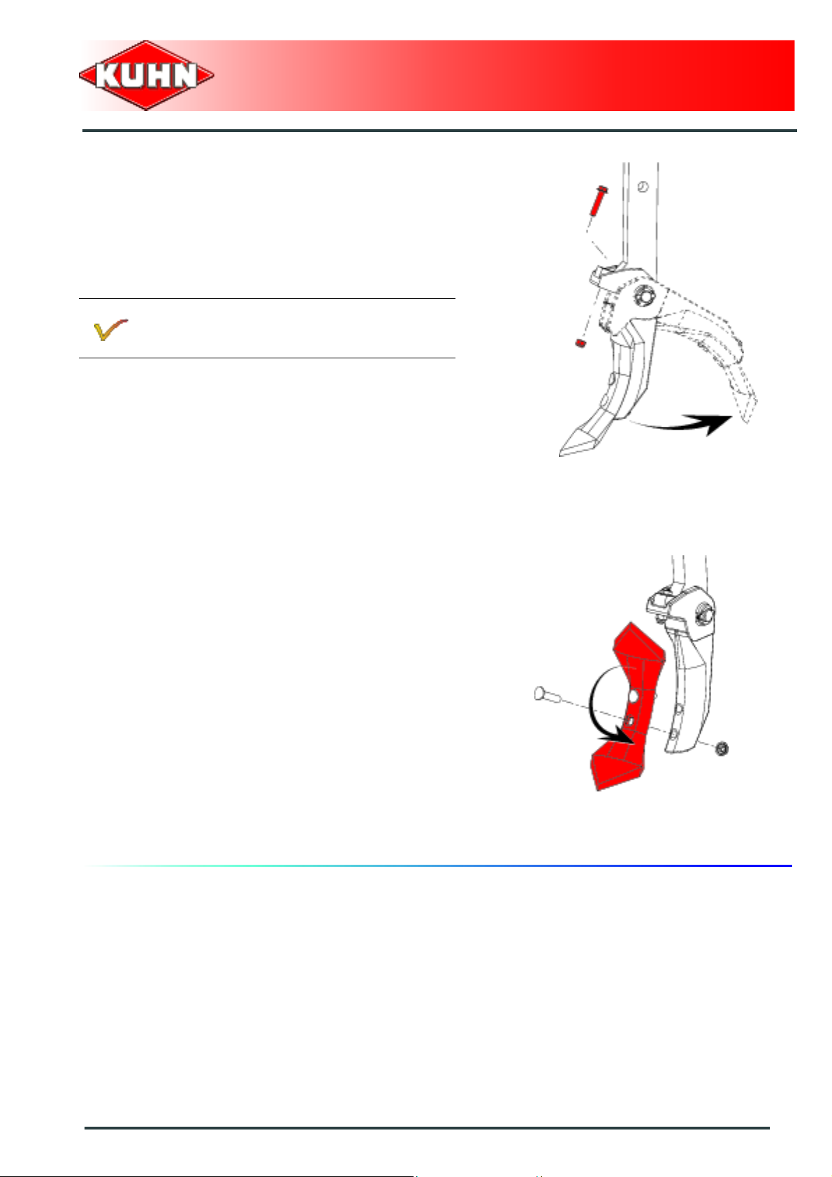
- Raise front loosening share:
Insert and lock pin (1) in the lower hole underneath pin
(2).
Check that there is no interference with the
tractor when the machine is in the raised
position.
The machine is in transport position.
Never engage the tractor PTO drive when the
machine is in transport position.
44
Instructions for transport
Page 47

2. Conformity with the road regulations
Before driving the machine on public roads,
ensure that the machine complies with
current highway code regulations.
Always keep to the legal height limit for
driving a tractor-machine assembly on public
roads.
Check that the light boards are clean and that the lighting
equipment functions before transporting the machine on
public roads. Check that transport locks (1) are fully
engaged.
Power harrow
HR6004DR
Immediately replace any worn or damaged
signalling panels or lights.
During transport, adapt the travel speed to
suit the road conditions.
Instructions for transport
45
Page 48
$Instructions for work
1. Putting the machine into work position
Before placing the machine in working
position:
- Check that nobody is within the machine
pivoting area.
- If there is someone, make sure the
person moves away.
Power harrow
HR6004DR
From the transport position:
- Raise the tractor lift linkage to provide sufficient
ground clearance of working parts.
- Activate half-harrow lift cylinder control valves to
release locks.
- Pull on release cord.
- Activate half-harrow cylinder control valves to lower
the half-harrows in work position.
- Lower front loosening share:
• Insert and lock pin (1) in the lower hole underneath
pin (2).
• To adjust the front loosening share working depth,
use the various holes of the mounting bracket.
The machine is in working position.
46
Instructions for work
Page 49

2. Adjustments in working position
Before placing the machine in working
position:
- Check that nobody is within the machine
pivoting area.
- If there is someone, make sure the
person moves away.
Rigid/floating working position.
The machine can operate in two ways:
Rigid position: (a)
The half-harrows are locked on the frame and work like
a rigid harrow: Improved soil levelling.
Floating position: (b)
The half-harrow outboard sides have a travel range of 100 mm to approximately +100 mm (-4’’/+4’’): The
floating position provides contour following on irregular
ground.
The machine is factory set in rigid position.
Setting to floating position:
- Remove roll pin (1) and washer (2).
- Check that the pin is not under load: If necessary,
activate transport/work cylinder control valves of the
half-harrows to free pin.
- Remove pin (3).
- Remove and rotate square spacers (4) through 90° to
bring the slot to a horizontal position.
- Reinstall pin (3).
- Reinstall washer (2) and roll pin (1).
- Repeat procedure on the second half-harrow.
Power harrow
HR6004DR
The machine is in floating position.
The two half-harrows must be in the same
working position.
Reverse the sequence to put the slot in vertical position
and the machine in rigid position.
Instructions for work
47
Page 50
Working depth
The roller provides working depth adjustment and
control.
Fit the adjustment pin (2) in one of the adjusting plate
holes (1) to adapt the working depth.
Fit adjustment pins in the same hole on both
sides of the machine.
Power harrow
HR6004DR
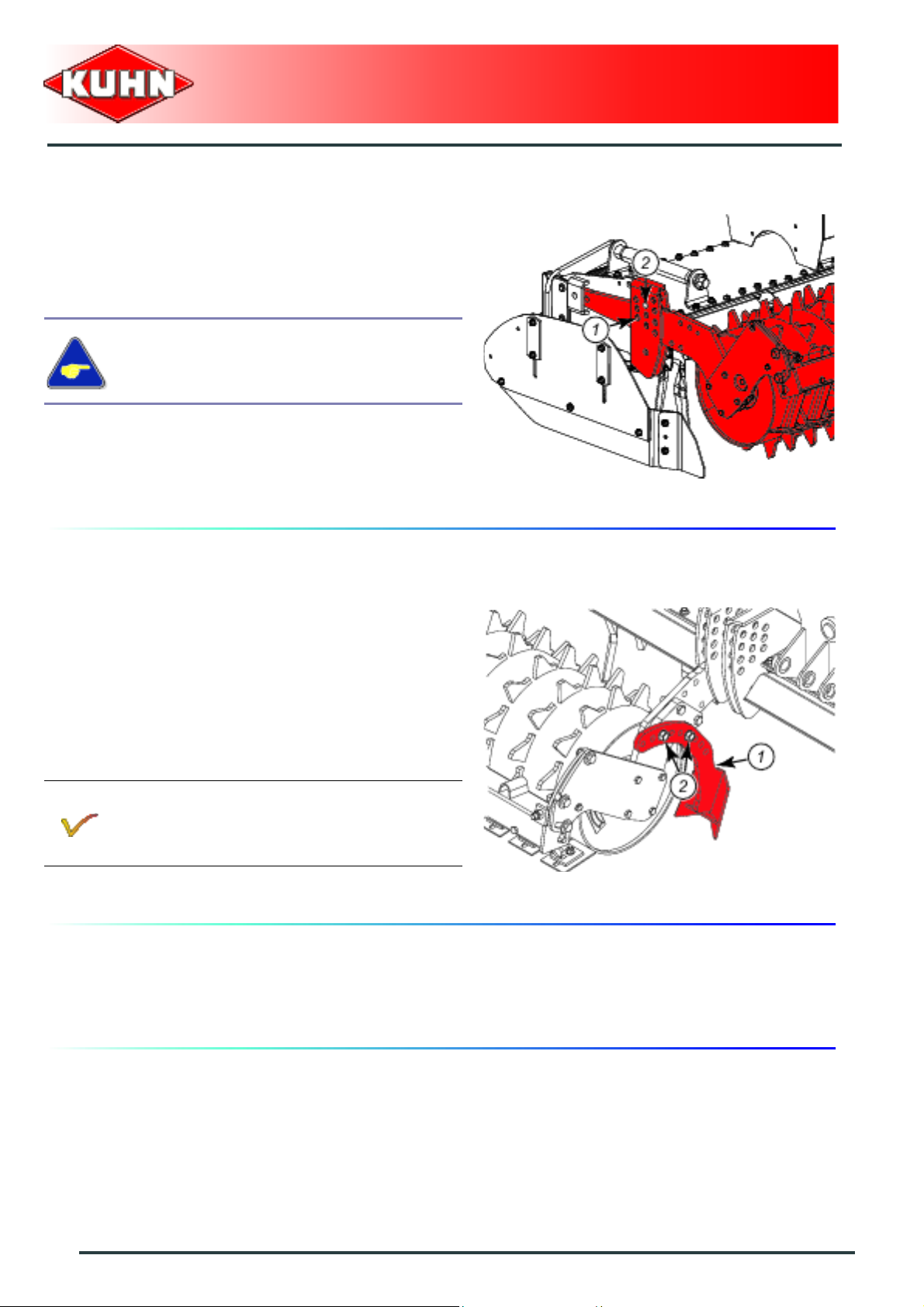
Rear levelling share
The rear levelling share levels the ridge which forms
between the two half-harrows. The rear levelling share is
fitted on the inner left roller arm (1) of the machine.
Setting the rear levelling share in working position.
The rear levelling share is adjusted according to:
- The working depth.
- The soil nature.
- The crumbling degree.
Dry conditions and/or fine crumbling = low
position.
Wet conditions and/or larger clods = high
position.
- Adjust the share height using 2 bo lts (2). Tightening
torque: 12 daN m (89 lbf ft).
Side deflectors anti-ridging plates.
Adjust side deflector anti-ridging plates according to the
working depth. (See section ’’Side deflector anti-ridging
plate adjustment’’).
48
Instructions for work
Page 51

3. Machine use
Before leaving the tractor or before
adjusting, maintaining or repairing the
machine, disengage the PTO drive, turn off
the engine, remove ignition key and wait until
all moving parts have come to a complete
stop and apply park brake.
- Lower machine until blades are at 100 - 150 mm (3.9’’
- 5.9’’) from the ground.
- Engage tractor PTO drive before working with the
machine.
Engaging the machine in the ground before engaging the tractor PTO can lead to excessive
power requirement and trigger the torque limiter.
Power harrow
HR6004DR
- Lower the machine progressively while on the move.
- Do not disengage PTO and do not stop tractor before
having lifted the machine from the ground.
Only work in straight lines. Lift the machine to turn.
Use of the power harrow entails limits which must be respected in all situations and that are
often related to:
- Weather conditions: Avoid working during an d immediately after rain, wait until the ground
to be worked is completely drained.
- Soil types: Smooth clods indicate too malleable or too humid soil to be worked in; Wait until
ground is completely drained. Soil concistency is ideal when clods crumble without
sticking.
- Tractor power: Adapt working depth, spe ed and rotor speed to power available and work to
be carried out. Never exceed the maximum allowable DIN engine power: 206 kW (280 hp).
- The nature of the work: the power harrow is an excellent implement for secondary tillage
and seedbed preparation after conventional ploughing, ch isel ploughing or soil loo sen in g.
It is far less efficient for primary tillage work especially on hard and dry ground.
The clod size depends on:
- The rotor speed.
- The forward speed.
- The working depth.
- the use of levelling bars (Optional equipment).
Example: large clods result from a low rotor speed and a high forward speed.
Instructions for work
49
Page 52

Groundspeed
Groundspeed must be adapted to the encountered
working conditions.
Power harrow
HR6004DR
50
Instructions for work
Page 53

1. Set of gearwheels
2 gearwheel sets are necessary to equip th e 2
half-harrows.
Kit no. 1237420
Set of 19 and 26 teeth gearwheels.
Power harrow
HR6004DR
$Optional equipment
Kit no. 1237650
Set of 17 and 28 teeth gearwheels.
Refer to the decal fitted on the machine .
Optional equipment
51
Page 54

2. Hydraulic lift linkage
Kit no. 1238380
This equipment allows an additional machine to be
coupled.
The equipment is composed of:
• A 3-point hydraulic attachment category 2.
Lift capacity of approximately 2500 daN
(5620 lbf) for a tractor pressure of 180 bar
(2610 psi).
Location and description of safety decals on the machine
Power harrow
HR6004DR
Location of safety decals
52
Optional equipment
Page 55
Description of safety decals
Crushing area (1)
Never operate in an area where there is a crushing risk
before all moving parts have come to a complete stop.
Additional machine lowering (2)
Make sure that the additional machine rests on the
ground:
- Before turning off the engine
- Before carrying out any maintenance or repair on the
machine
- Before parking the assembly
Crushing hazard.
Power harrow
HR6004DR
Putting into service
Hydraulic connection
Connect hydraulic hose (1) to a single acting outlet.
Adjustments
Attachment brackets:
The attachment hooks can be fitted in 6 different
positions to obtain best adaptation of the additional
machine.
Tightening torque: 42 daN m (309 lbf ft):
Optional equipment
53
Page 56

Stroke limiters:
This part has several functions:
- Avoid any interference between the
machine components during halfharrow folding manoeuvres and when
raising the additional machine.
- Protect the PTO shaft in case of driven
combinations.
- Couple up the PTO shaft (bet ween th e powe r harr ow
and the additional machine).
- Lift the combined machine using the rear hydraulic lift
linkage:
• When the PTO shaft is in its maximum overlap
position (retracted), tubes should not butt against
the yokes. As a safety measure, a clearance (L) of
at least 25 mm (1’’) must be maintained.
- Tighten the assembly using nut (1).
Power harrow
HR6004DR
Machine use
By fitting the hydraulic attachment stroke limiters, the
additional machine can be raised by 600 to 700 mm
(23.6’’ - 27.5’’) while folding the half-harrows.
By removing the stroke limiters, the additional machine
can be fully raised.
If the power harrow is used with an additional
PTO driven machine, make s ure to uncoup le
PTO shaft before fully raising the additional
machine.
54
Optional equipment
Page 57

Parking
When parking the power harrow/additional
machine unit, make sure that the ad ditional
machine is lowered first.
Instructions for transport
Putting the machine into transport position
When stroke limiters are fitted, the halfharrows can be fully folded without risk of
interferences with the additional machine.
When the stroke limiters have been removed,
do not raise the half-harrows due to the risk
of interference with the signalling panels.
Power harrow
HR6004DR
Maintenance
Every 100 hours
Grease:
- Pivot points.
Optional equipment
55
Page 58
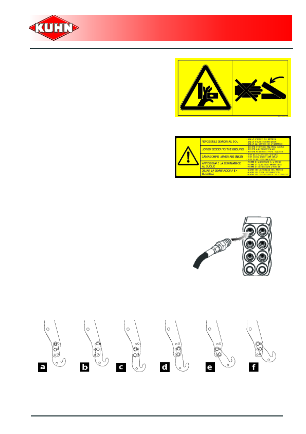
3. Track eradicators
The track eradicators reduce tractor wheel marks in the
seedbed.
The equipment is composed of:
- A set of tine holders Kit no. 1238870.
- A set of 2 track eradicator tines:
• With traction bolt overload mechanism: Kit
no. 1216610 (a).
or
• With spring overload mechanism: Kit
no. 1216620 (b).
Only use track eradicators for secondary tillage
work.
Power harrow
HR6004DR
Lateral adjustment
- Loosen U-bolts (1).
- Track eradicators must be mounted centrally to the
tractor wheels.
- Tighten U-bolts (1).
Torque: 21 daN m (155 lbf ft).
Fit additional track eradicators when using wide tyres or
dual wheels.
2 track eradicators with traction bolt overload
mechanism: Kit no. 1216610.
2 track eradicators with spring overload
mechanism: Kit no. 1216620.
Working depth adjustment
Adjust the track eradicator working depth using pin (2).
56
Optional equipment
The track eradicator working depth must not
exceed 100 mm (4’’).
Page 59
The track eradicators are fitted with an overload
mechanism should they encounter an obstacle:
- With traction bolt overload mechanism:
Bolt breaks: (Part no. 80131051).
- With spring overload mechanism:
The track eradicator automatically resets to its work
position after having cleared the obstacle.
Track eradicators with the spring overload
mechanism are recommended for work in
difficult or stony grounds.
Power harrow
HR6004DR
- Each track eradicator share is reversible for increased
service life. Replace it if necessary.
Torque: 10 daN m (74 lbf ft).
Optional equipment
57
Page 60

4. Front and rear levelling bar
Kit no. 1238370
Levelling bars can be fitted to the front or rear of the
corresponding half-harrow.
Fitting and adjusting the levelling bars.
Fit levelling bars so that their angled edges
face towards the machine fron t (direction of
travel).
Front position
The front levelling bars level irregular grounds and help
break up dry clods.
Rear position
The rear levelling bars increase the degree of crumbling
in dry soils and the roller efficiency in sandy soils.
Power harrow
HR6004DR
The rear levelling bars are not recommended in
wet and sticky soils, and when there are a lot of
stones.
Rear levelling bars increase the machine
horsepower requirement. Remove levelling
bars if they are not required in work.
Adjust levelling bars using pins (1).
Adjust levelling bars according to:
- The soil conditions.
- The working depth.
The height adjustment is co rrect when the soil
flow hits the rear levelling bar. Make sure there is
enough clearance between the lower edge and
the ground to allow soil to move towards the
rollers.
Both half-harrow levelling bars must be set in
the same position.
58
Optional equipment
Page 61

5. Rollers
The roller is used as a protection device at
the rear of the machine. It must never be
removed for work.
The roller is an essential element of the harrow and has
the following 4 functions:
- Set and control the working depth.
- To pack the soil evenly behind the rotors and create
an optimum seedbed.
- To increase seedbed crumbling and clod break-up.
- To improve seedbed levelling.
Maxicrumbler roller: Part no. 1209150
The Maxicrumbler roller is adapted to dry or slightly wet
soils.
Power harrow
HR6004DR
or
Packer PK2 roller: Part no. 1237010
The Packer PK2 roller is adapted to soils which are
subject to capping or very clayey and sticky. The roller is
fitted with a scraper bar. Scraper plates are located
between the rows of studs to ensure roller cleaning.
Optional equipment
59
Page 62
or
Maxipacker roller: Part no. 1238420
The Maxipacker roller is adapted to all soil types and
particularly to wet and sticky soils. The roller is fitted with
a scraper bar. Scraper plates are located between the
rows of studs to ensure roller cleaning.
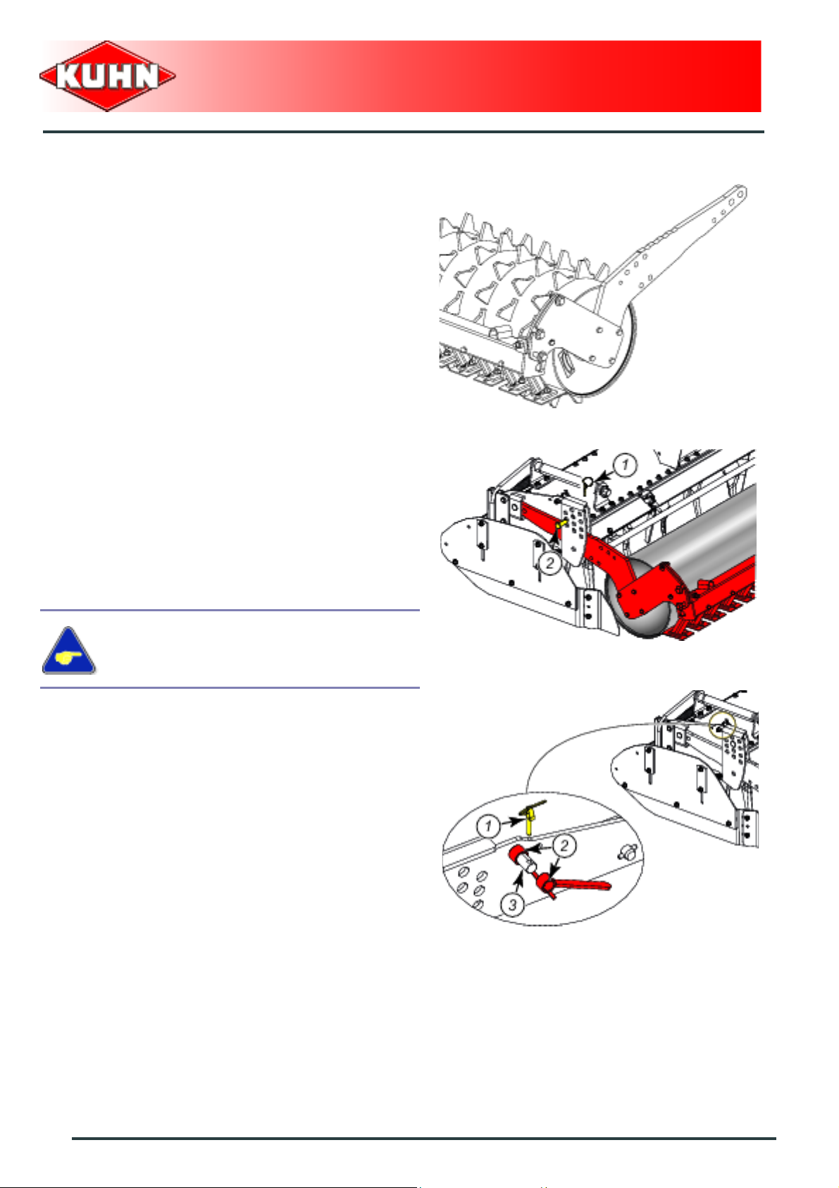
Adjustments
The roller provides working depth adjustment and
control.
- Raise the power harrow.
- Remove lynch pin (1).
- Position adjustment pin (2) in on e of the holes of the
adjustment plate that corresponds to the required
setting.
- Insert and lock lynch pin (1).
Power harrow
HR6004DR
Fit adjustment pins in the same hole on both
sides of the machine.
The bushes (2) supplied wi th the machine provide fine
adjustment of the roll position.
- Raise the power harrow.
- Remove lynch pin (1).
- Remove bushes (2) from holder (3).
60
Optional equipment
Page 63

- Remove lynch pin (1).
- Remove adjustment pin (2).
- Position bush inside the multihole plate (3) in front of
the hole thar corresponds to the required setting.
- Position adjustment pin (2) in the adjustment plate
hole that corresponds to the required setting. Pin (2)
must pass through the bush.
- Insert and lock lynch pin (1).
Fit adjustment pins in the same ho le on both
sides of the machine.
Power harrow
HR6004DR
Optional equipment
61
Page 64

Before leaving the tractor or before
adjusting, maintaining or repairing the
machine, disengage the PTO drive, turn off
the engine, remove ignition key and wait until
all moving parts have come to a complete
stop and apply park brake.
1. Frequency chart
Power harrow
HR6004DR
$Maintenance and storage
Oil change:
- The main gearbox.
- Cooling system tank
- The side gearboxes.
Grease:
- Roller bearing housings.
- Cylinder pins.
- The foldable frame pivot points.
After the first
10 hours of
use
Every 20
hours
Every 100
hours
33
33
33
3
3
3
62
Maintenance and storage
Page 65

2. Cleaning the machine
Regularly check that there are no foreign
objects wrapped around the blade
holder(twine, wire, crop residues,...). To
prevent premature bearing housing wear,
remove foreign bodies wrapped around
them.
- Regularly check side deflectors.
- Keep all transport locks clean.
- Regularly clean roller and roller scraper bar:
In case of clogging, pivot scraper crossbar:
Packer PK2 roller: (a)
• Unscrew the 4 nuts (1).
• Remove the 2 tensioning devices (2).
• Slide lever in sleeves (3).
• Pivot scraper bar using lever.
• Clean and reassemble the unit.
Tightening torque: (1) 22 daN m (162 lbf ft).
• Proceed the same way with the second scraper
crossbar.
Power harrow
HR6004DR
Maxipacker roller: (b)
• Unscrew the 6 nuts (1).
• Remove the 2 tensioning devices (2).
• Slide lever in sleeves (3).
• Pivot scraper bar using lever.
• Clean and reassemble the unit.
Tightening torque: (1) 22 daN m (162 lbf ft).
• Proceed the same way with the second scraper
crossbar.
Maintenance and storage
63
Page 66
3. Lubrication
Except for the secondary PTO shaft lubrication, the
machine must be placed in transport position for all
maintenance operations.
Clean grease nipples before greasing.
Lubricate with SHELL multi-purpose grease
grade NLGI 2.
Power harrow
HR6004DR
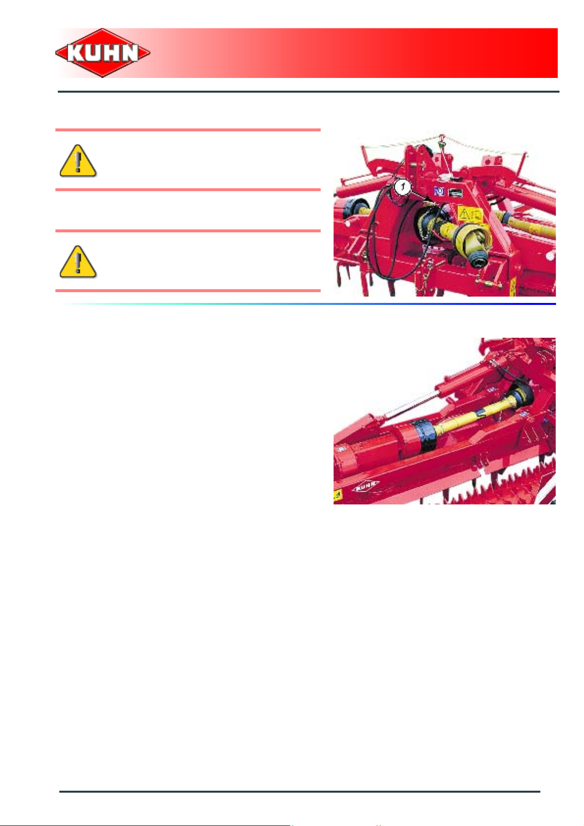
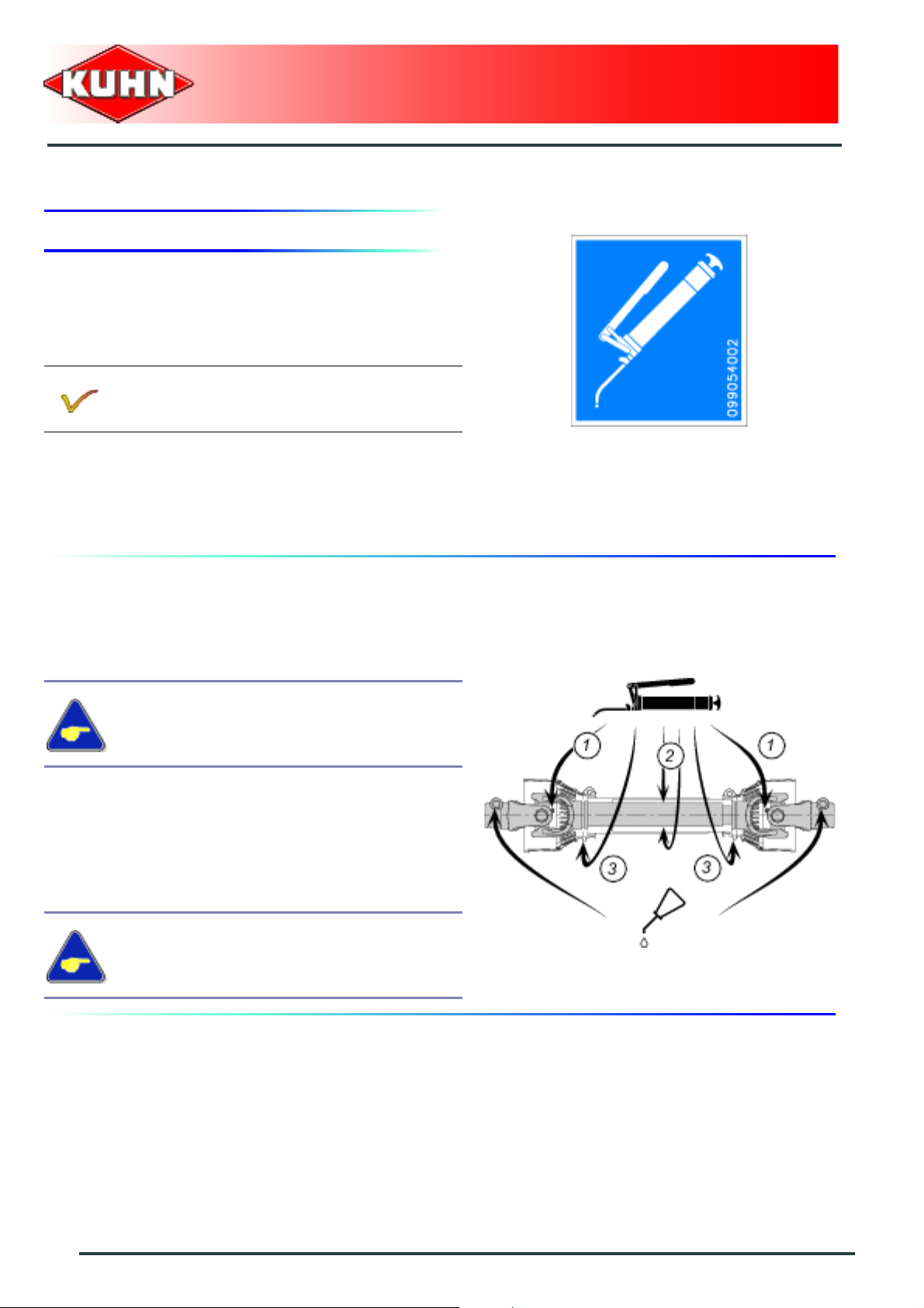
Intermediate PTO shaft 1
Every 250 hours or at the end of the season:
- U-joints (1).
- Transmission tube:
To access the 2 grease nipples (2) to grease
(Slide the black collar).
- guide rings (3):
• Unlock and slide guards for easier greasing of the
PTO shaft u-joints and guiding bushes.
Each time the 2 half-PTO shafts are split:
- Transmission tube (The two grease nipples (2)).
During intensive use with tractors of
maximum authorized power, it is
recommended to grease at closer intervals
(Interval of 100 to 150 hours).
64
Maintenance and storage
Page 67
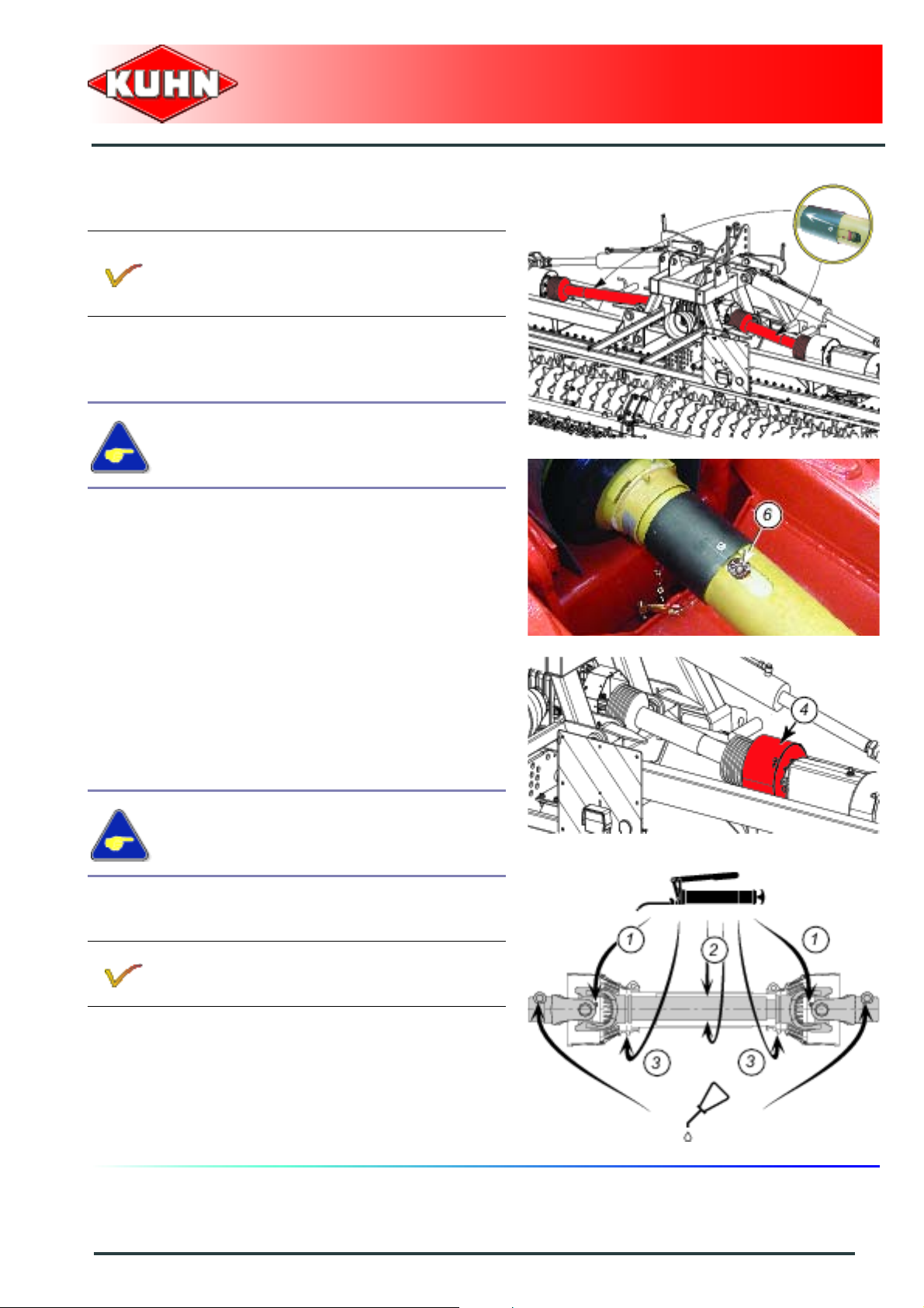
Intermediate PTO shaft 2
Place the machine in working position.
Turn off the engine, remove ignition key and wait
until all moving parts have come to a complete
stop.
Every 250 hours or at the end of the season:
- Transmission tube:
To access the 2 grease nipples (2) to grease.
• Slide the black collar.
• If necessary, rotate one rotor to access the grease
nipple (6).
• Slide the black collar back in place when lubrication
has been completed.
- U-joints (1).
• Remove gearbox protection (4) to access U-joint
greaser on lateral gearbox side.
- guide rings (3):
• Unlock and slide guards for easier greasing of the
PTO shaft u-joints and guiding bushes.
Power harrow
HR6004DR
Each time the 2 half-PTO shafts are split:
- Transmission tube (The two grease nipples (2)).
During intensive use with tractors of
maximum authorized power, it is
recommended to grease at closer intervals
(Interval of 100 to 150 hours).
Repeat procedure on the second intermediate
PTO shaft 2.
Maintenance and storage
65
Page 68

Trough
Each main trough is greased for life with
23 kg (50.7 lb) SHELL ALVANIA WR0 grade
NLGI 0 semi-fluid grease.
Power harrow
HR6004DR
66
Maintenance and storage
Page 69

Draining:
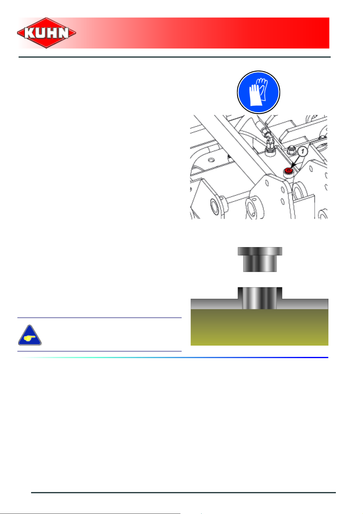
The main gearbox
Before draining oil, operate the machine for a
few minutes so that the oil warms up.
The main gearbox is lubricated with 3.75 L (1 US gal) of SHELL SPIRAX A extreme-pressure gear oil
with viscosity grade 80W90 and API grade GL5.
When refilling it is recommended to use:
For normal use:
- A mineral base oil with viscosity grade SAE 80W90 or 85W140 and API grade GL5
For intensive use:
- A synthetic base oil, type PAO (Poly-Alpha-Olefins) with a viscosity grade equivalent to
Power harrow
HR6004DR
(SHELL SPIRAX A 80W90 or SHELL SPIRAX A 85W140).
SAE 80W90 or 85W140 and API grade GL5 (SHELL SPIRAX ASX 75W90).
From the working position:
- Lower the tractor three-point linkage to rest the
machine on the ground.
- Increase top link length to tilt the machine rearwards.
- Place a container of sufficient capacity under drain
plug (3).
- Remove filler plug (2) and its washer.
- Remove drain plug (3) and its washer.
- Allow oil to drain completely.
- Wait for dripping to stop.
- Clean and reinstall drain plug (3) and its washer.
Replace if necessary.
- Adjust the top link length so that the machine is
horizontal with regards to the ground.
- Pour the correct oil quantity and quality through the
opening of the filler plug (2).
- Clean and reinstall filler plug (2) and its washer.
Replace if necessary.
Checking the oil level:
- Place the machine on level ground.
- Remove level plug (1).
• The oil level must reach the lower edge of level hole
(1).
- Clean and reinstall drain plug (1).
Maintenance and storage
67
Page 70

Power harrow
HR6004DR
Cooling system tank
Before draining oil, operate the machine for a
few minutes so that the oil warms up.
The cooling system tank contains 5.3 L (1.4 US gal) of SHELL SPIRAX A extreme-pressure oil for
mechanical transmissions with viscosity grade 80W90 and API grade GL5
When refilling it is recommended to use:
For normal use:
- A mineral base oil with viscosity grade SAE 80W90 or 85W140 and API grade GL5
(SHELL SPIRAX A 80W90 or SHELL SPIRAX A 85W140).
For intensive use:
- A synthetic base oil, type PAO (Poly-Alpha-Olefins) with a viscosity grade equivalent to
SAE 80W90 or 85W140 and API grade GL5 (SHELL SPIRAX ASX 75W90).
From the working position:
- Park the machine on an even fairly level ground.
- Position intermediate coupling frame tube horizontally
lengthways and crosswise.
- Remove filler plug (1) and its washer.
- Place container underneath hydraulic hose connector
(2).
- Remove hydraulic hose (2) on valve side.
- Allow oil to drain completely.
- Wait for dripping to stop.
- Clean and reinstall hydraulic hose (2).
- Remove hydraulic hose (3).
- Pour prescribed oil quality through filler plug opening
until top full (1).
- Clean and reinstall hydraulic hose (3).
- Clean and reinstall filler plug (2) and its washer.
Replace if necessary.
68
Maintenance and storage
Page 71

Power harrow
HR6004DR
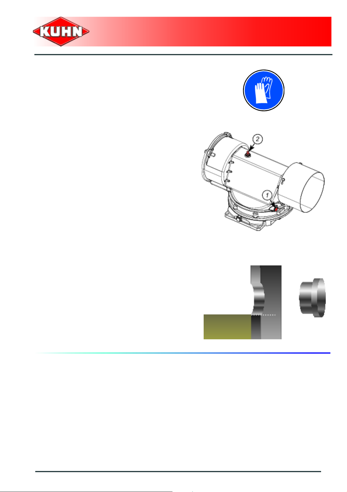
The side gearboxes
Before draining oil, operate the machine for a
few minutes so that the oil warms up.
Each side gearbox is lubricated with 5 L (1.32 US gal) of SHELL SPIRAX A extreme-pressure gear oil
with viscosity grade 80W90 and API grade GL5.
When refilling it is recommended to use:
For normal use:
- A mineral base oil with viscosity grade SAE 80W90 or 85W140 and API grade GL5
(SHELL SPIRAX A 80W90 or SHELL SPIRAX A 85W140).
For intensive use:
- A synthetic base oil, type PAO (Poly-Alpha-Olefins) with a viscosity grade equivalent to
SAE 80W90 or 85W140 and API grade GL5 (SHELL SPIRAX ASX 75W90).
From the working position:
- Lower the tractor three-point linkage to rest the
machine on the ground.
- Increase top link length to tilt the machine rearwards.
- Place a container of sufficient capacity under drain
plug (1).
- Remove filler plug (2) and its washer.
- Remove drain plug (1) and its washer.
- Allow oil to drain completely.
- Wait for dripping to stop.
- Clean and reinstall drain plug (1) and its washer.
Replace if necessary.
- Adjust the top link length so that the machine is
horizontal with regards to the ground.
- Pour the correct oil quantity and quality through the
opening of the filler plug (2).
- Clean and reinstall filler plug (2) and its washer.
Replace if necessary.
Checking the oil level:
- Place the machine on level ground.
- Remove level plug (3).
• The oil level must reach the lower edge of level hole
(3).
- Clean and reinstall drain plug (3).
Maintenance and storage
69
Page 72

Grease:
- The 4 roller housing bearings (1).
Power harrow
HR6004DR
- Cylinder pins (1).
- The foldable frame pivot points (2).
70
Maintenance and storage
Page 73

4. Maintenance
Before leaving the tractor or before
adjusting, maintaining or repairing the
machine, disengage the PTO drive, turn off
the engine, remove ignition key and wait until
all moving parts have come to a complete
stop and apply park brake.
Checking the oil levels
Central gearbox
From the working position:
- Place the machine on level ground.
- Remove level plug (1).
- Check the oil level.
- Top up if necessary.
- Clean and replace the oil level cap (1). Replace it if
necessary.
Power harrow
HR6004DR
Checking the oil level:
- Remove level plug (1).
• The oil level must reach the lower edge of level hole
(1).
- Clean and replace the oil level cap (1). Replace it if
necessary.
Check that there are no oil leaks on th e centra l gear box.
Maintenance and storage
71
Page 74
Cooling system tank
From the working position:
- Operate the machine for a few minutes so that the oil
flows through the whole circuit (Minimum: 5 minutes).
- Place the machine on level ground.
- Remove level plug (1).
- Check the oil level.
- Clean and replace the oil level cap (1). Replace it if
necessary.
Power harrow
HR6004DR
Checking the oil level:
- Remove level plug (1).
• The cooling system tank must be filled to the brim.
- Clean and replace the oil level cap (1). Replace it if
necessary.
If the oil level is insufficient, check the whole
circuit for a leak and contact your Kuhn
authorized dealer.
72
Maintenance and storage
Page 75
Side gearbox
- Place the machine on level ground.
- Remove level plug (1).
- Check the oil level.
- Top up if necessary.
- Clean and replace the oil level cap (1). Replace it if
necessary.
- Clean and reinstall filler plug (2) and its washer.
Replace if necessary.
Power harrow
HR6004DR
Checking the oil level:
- Remove level plug (1).
• The oil level must reach the lower edge of level hole
(1).
- Clean and replace the oil level cap (1). Replace it if
necessary.
Check that there are no oil leaks on the side gearboxes.
Maintenance and storage
73
Page 76

Checking the blades and their mounting
hardware
Immediately replace worn or damaged parts with
genuine KUHN parts.
Blades
Replace blades in the following cases:
- When the degree of wear L reaches 150 mm (6’’).
- When there is visible distortion.
Using blades that are excessively worn can
cause premature damage to holders, rotors or
troughs.
We recommend to use hard coated blades in
abrasive soils:
DURAKUHN hard coated blade rotating to the
left (Part no. K2500260).
DURAKUHN hard coated blade rotating to the
right (Part no. K2500270).
Power harrow
HR6004DR
Regularly check that there are no foreign
objects wrapped around the blade holder
(twine, wire, crop residues,...). Remove them.
74
Maintenance and storage
Page 77
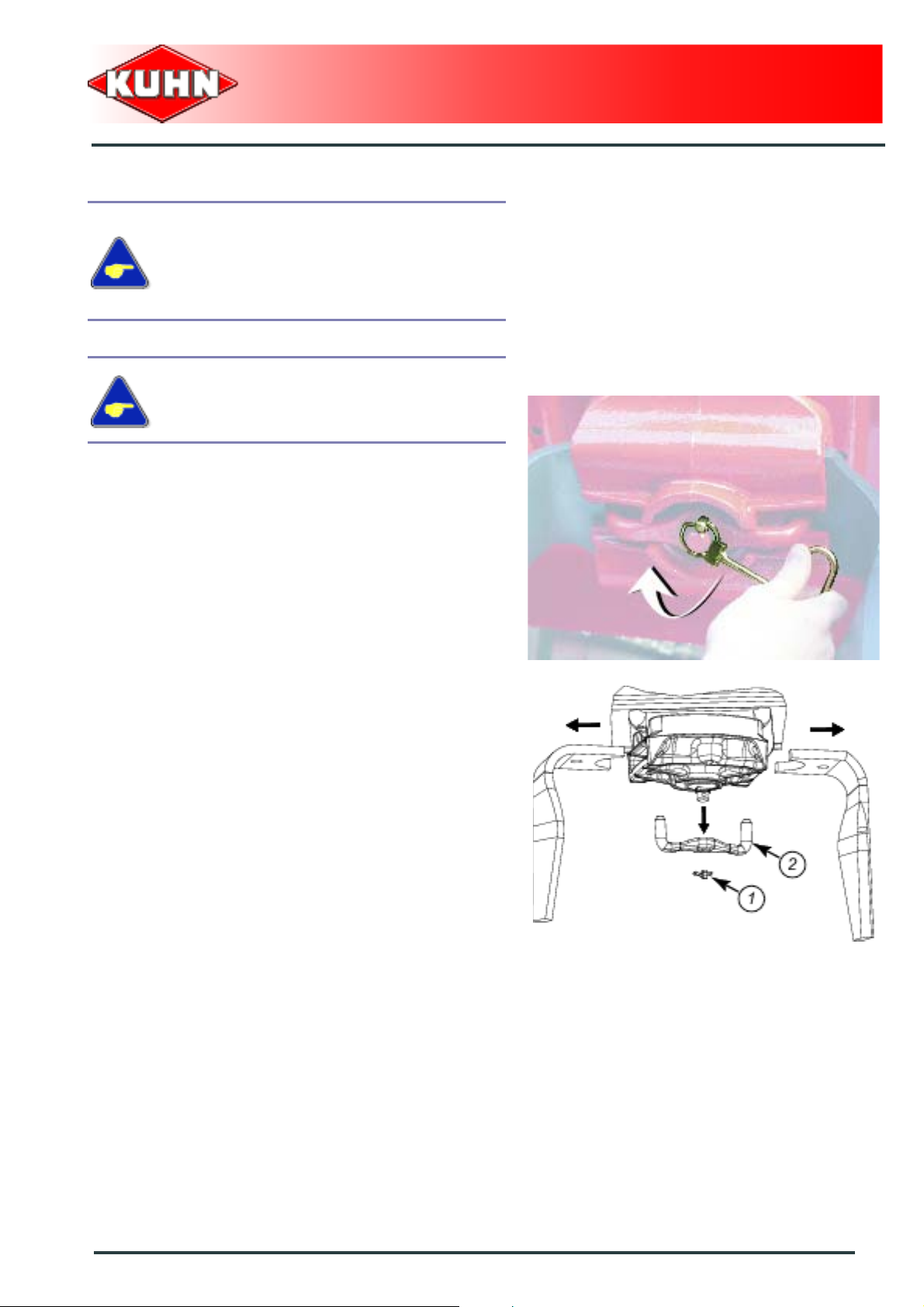
Blade replacement
Before leaving the tractor or before
adjusting, maintaining or repairing the
machine, disengage the PTO drive, turn off
the engine, remove ignition key and wait until
all moving parts have come to a complete
stop and apply park brake
From the transport position:
Check that locks are engaged.
- Clean the blade holder to clear the lynch pin.
- Pivot lynch pin ring using unlocking key supplied with
the machine (Part no. 52598210).
Power harrow
HR6004DR
- Remove lynch pin (1).
- Remove connecting piece (2).
Maintenance and storage
75
Page 78

- Replace worn blades.
Blade rotating to the left (4):
- Standard blade: (Part no. K2500090).
- OPTIMIX blade: (Part no. K2501120).
- DURAKUHN blade: (Part no. K2500260).
Blade rotating to the right (3):
- Standard blade: (Part no. K2500100).
- OPTIMIX blade: (Part no. K2501130).
- DURAKUHN blade: (Part no. K2500270).
Power harrow
HR6004DR
Rotor direction of rotation:
- Reassemble the unit.
- Check the condition of the lynch pin (replace it if
necessary) Part no. 50086310.
- Repeat the procedure for each rotor.
Fixing elements
Check the condition of the lynch pins after each blade
replacement. Replace them if necessary.
Replace lynch pins every 2 or 3 blade replacement.
76
Maintenance and storage
Page 79
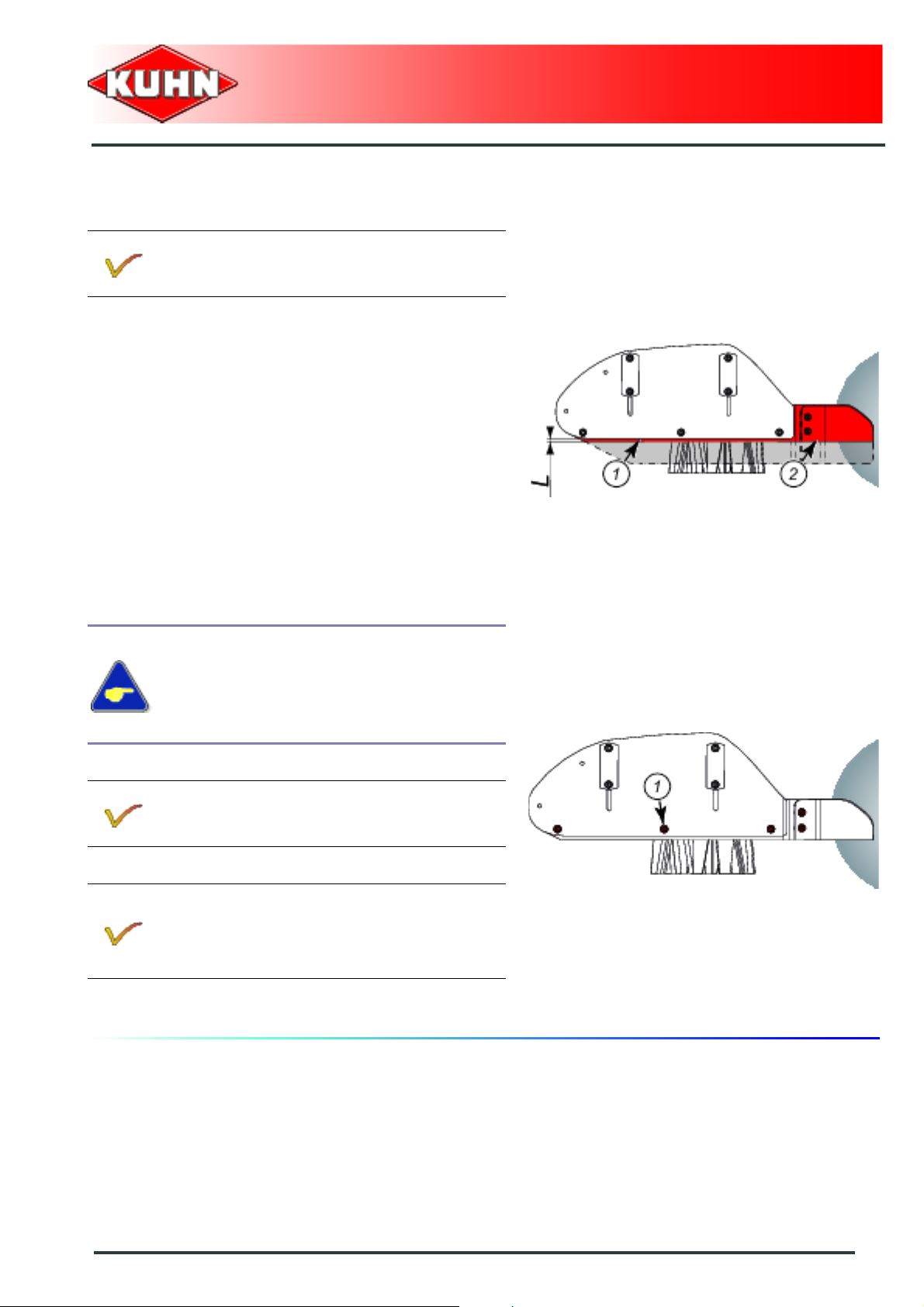
Checking the side deflectors
Immediately replace worn or damaged parts with
genuine KUHN parts.
Side deflectors
Replace side deflectors (1) and anti-ridging plates (2)
when measure L reaches 20 mm (0.79’’).
Power harrow
HR6004DR
Side deflector replacement
Before leaving the tractor or before
adjusting, maintaining or repairing the
machine, disengage the PTO drive, turn off
the engine, remove ignition key and wait until
all moving parts have come to a complete
stop and apply park brake.
- Remove screws and nuts (1). Replace if necessary.
Bolt: Part no. 50070800.
Nut: Part no. 80201265.
- Replacing the side deflectors and anti-ridging plates.
Right side deflector: Part no. K2602020.
Right anti-ridging plate: Part no. K2601380.
Left side deflector: Part no. K2602010.
Left anti-ridging plate: Part no. K2601370.
- Reinstall bolts and nuts (1):
• Torque: 8.5 daNm (62.5 lbf ft)
Maintenance and storage
77
Page 80

Oil seal replacement
Before removing the blade holder, mark its
initial direction to ensure it is refitted
correctly.
Never remove several blade holders at the
same time.
Blade holder position
Power harrow
HR6004DR
78
Maintenance and storage
Page 81
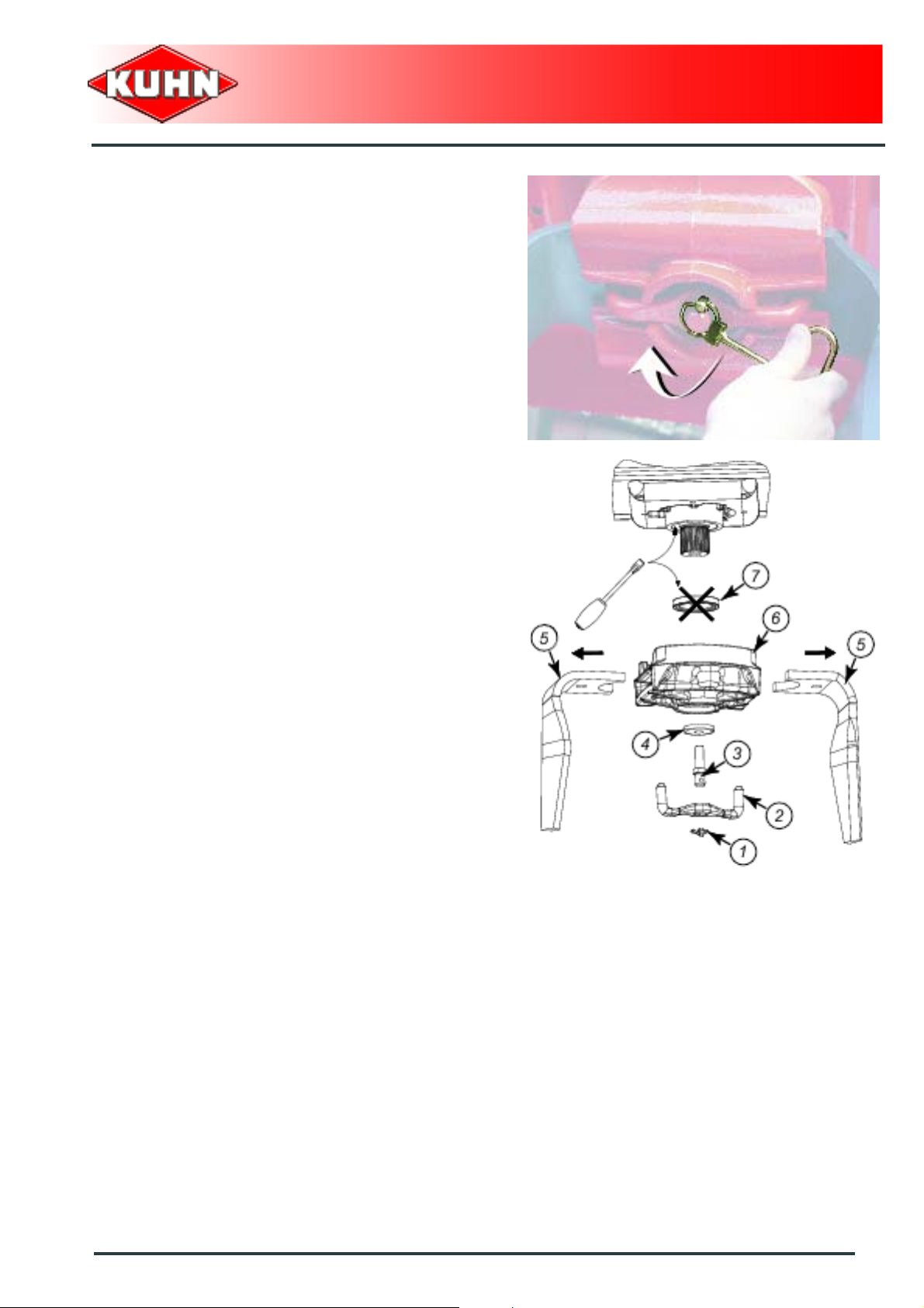
- Clean the blade holder to clear the lynch pin.
- Pivot lynch pin ring using unlocking key supplied with
the machine (Part no. 52598210).
Power harrow
HR6004DR
- Remove lynch pin (1).
- Remove connecting piece (2).
- Loosen screw (3).
- Remove washer (4).
- Remove blades (5).
- Remove blade holder (6).
- Remove oil seal (7) using a screwdriver.
Maintenance and storage
79
Page 82

- Clean and lubricate oil seal housing.
- Fit new oil seal using special tool (8) (Part
no. K2501870).
The oil seal is in place when tool (8) bottoms
against input shaft (9).
Note oil seal mounting direction.
Power harrow
HR6004DR
- Grease the input shaft before reassembling all
components.
- Torque screw (3) to: 30 daN m (221 lbf ft).
80
Maintenance and storage
Page 83

5. Storage
At the end of each season
- Clean the machine with a garden hose.
- Check and replace worn or damaged blades.
- Check and replace worn or damaged scraper plates.
- Touch up any areas of damaged paintwork.
- Put the machine under cover in a dry place.
- Remove and service the PTO shaft. Follow the
instructions in the PTO shaft operating manual.
At the start of each season
- Re-read the operators' manual.
- Check that the lighting equipment is clean.
- Check that all nuts and bolts are sufficiently tightened.
- Make sure that all protection devices are in place and
in good condition.
Power harrow
HR6004DR
Maintenance and storage
81
Page 84

$Trouble shooting guide
-
Problem Cause Remedy
Noisy drive when lifting the
machine
Noisy drive during work
Excessive power requirement
Tilth produced is too coarse
Tilth produced is too fine
Ridging at the side of the
machine
Excessive wear on blades and
blade holders
Top link of 3-point hitch badly
positioned/adjusted
Excessive lifting height Limit the lift linkage stroke
Machine tilted to the front or
rear (excessive pitch angle)
Insufficient machine side to
side stabilization
Working depth too deep
Rotor speed too high
Excessive ground speed Reduce ground speed
Incorrect setting of the rear
levelling bars
Considerable build-up of long
plant residues around the
blades
Excessive ground speed Reduce ground speed
Rotor speed too low
No levelling bars
Rotor speed too high
Forward speed is too slow Increase forward speed
Rear levelling bars are too low
Anti-ridging plate incorrectly
positioned on the side
deflectors
PTO speed is too high Reduce PTO speed
Levelling bars mounted at the
rear
Position top link parallel to
lower linkage arms
Lengthen or shorten top link to
set the machine horizontally
during work. (Tractor pto shaft
end and machine input shaft
must be parallel)
Use lower linkage arm
stabilizers
Reduce working depth by
adjusting the roller height
Reduce speed using the side
gearboxes. (optional
gearwheel sets)
Raise or remove the levelling
bars
Eliminate plant residues
Increase speed at the side
gearboxes (optional gearwheel
sets)
Install levelling bars, preferably
towards the rear
Reduce speed using the side
gearboxes. (optional
gearwheel sets)
Raise or remove the levelling
bars
Position each anti-ridging plate
as close as possible to the
ground and roller
Remove rear levelling bars if
not required by working
conditions
Power harrow
HR6004DR
82
Trouble shooting guide
Page 85

Power harrow
HR6004DR
Machine clogging due to
ground build up between rotors
and levelling bars
Clogging of the Maxicrumbler
roller
Incorrect Packer roller
functioning (clogging, jamming
or soil build-up)
Ridging at the centre of the
machine
Rear levelling bars mounted in
wet conditions
Wet conditions, too high load
on the roller
Incorrectly adjusted or worn out
scraper plates
Scrapers jammed by trash
Scraper bars incorrectly
positioned
Rear levelling share incorrectly
positioned
Remove rear levelling bars
use Packer PK2 roller or
Maxipacker roller
Adjust each scraper plate
Clean scrapers by pivoting
them rearwards
Scraper bars must always be in
its furtherst forward position.
Wear compensation can only
be obtained by sliding the
scraper plates forward
individually
Adjust rear levelling share
height
Trouble shooting guide
83
Page 86

$Appendix
1. Calculating the load on an axle
When coupling a tool to the front and rear 3-point lift linkage, the maximum authorized payload must
not be exceeded.
The load on the tractor front axle must always represent 20 % of the tractor unladen weight.
Prior to use, check that these conditions ar e satisfied by making this calculation or by weighing the
tractor-machine unit
Define the total weight, axle loads, tyre
capacity and minimum additional mass:
Power harrow
HR6004DR
The following values are required for the calculation:
Description Units Description
T kg Tractor unladen weight
T1 kg Unladen load on tractor front axle
T2 kg Empty load on tractor rear axle
t kg Axle loads (Tractor + machine)
t1 kg Load on front axle (Tractor + machine)
t2 kg Load on rear axle (Tractor + machine)
M1 kg Total weight of front tool or front ballast
M2 kg Total weight of rear tool or rear ballast
am
b m Distance between the tractor axles
cm
d m
Distance between the tools' centre of gravity or the front ballast and
the front axle centre
Distance between the rear axle center and the center of the lower link
ball joints
Distance between the centre of the lower link ball joints and the centre
of gravity of the rear tool or rear ballast
Obtaine
d by
84
Refer to the tractor operators' manual Refer to the machine price-list or operators' manual
Dimensions Measure on scale
Appendix
Page 87

Rear tool or front-rear combination:
Power harrow
HR6004DR
1) Calculation of the minimum front ballast weight M1
minimum
M2 x (c+d) - T1 x b + 0.2 x T x b
M1
minimum
=
a+b
Write the minimal additional weight in the chart.
Front tool:
2) Calculation of the minimum rear ballast weight M2
minimum
M1 x a - T2 x b + 0.45 x T x b
M2
minimum
=
b+c+d
Write the minimal additional weight in the chart.
3) Calculation of the actual load on the front axle T1
If the front tool (M1) is lighter than the minimum load required at the front (minimum), increase tool weight until the required minimum
front load is reached
real
M1 x (a+b) + T1 x b - M2 x (c+d)
T1
=
real
b
Indicate front axle calculated load value and the one indicated in the tractor operators' manual.
4) Calculation of the total weight M
If the rear tool (M2) is lighter than the minimum load required at the rear(minimum), increase tool weight until the required minimum
rear load is reached
real
M
= M1 + T + M2
real
Indicate calculated total load value and the one autho rized as indicated in the tractor operator's manual.
5) Calculation of the actual rear axle load T2
T2
= M
real
real
real
- T1
real
Indicate rear axle calculated load value and the one indicated in the tractor operator's manual.
6) Tyre carrying capacity
Indicate double (2 tyres) the authorized load value (see tyre manufacturer indications).
Appendix
85
Page 88

Table:
Power harrow
HR6004DR
Actual value obtained
by calculation
Minimum front/rear
ballasting
Total weight kg ≤ kg
Load on front axle kg ≤ kg ≤ kg
Load on rear axle kg ≤ kg ≤ kg
The minimum ballasting must be made by fitting a tool or an additional mass to the
tractor.
The values obtained must be below or equal the authorized values.
kg
Value authorized
according to
operator's manual
Double value of the
authorized capacity
per tyre (2 tyres)
86
Appendix
Page 89

Determining the machine weight (M2) and the position of its centre of gravity (d)
If the data required to calculate the total
weight, axle loads and minimum ballasting
are not supplied, use the following method.
Tractor only:
Power harrow
HR6004DR
- T1: Load on front axle.
•Tractor only.
- T2: Load on rear axle.
•Tractor only.
Appendix
87
Page 90

- T: Axle loads.
• Tractor only.
Power harrow
HR6004DR
88
Appendix
Page 91
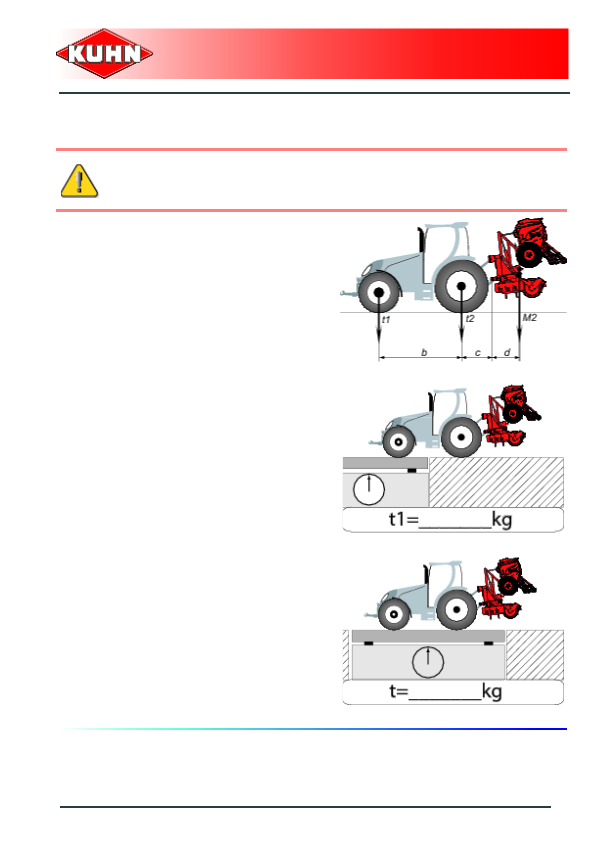
Power harrow
HR6004DR
Rear tool or front-rear combination:
If the total unit weight exceeds the tractor Gross Combined We ight Rating in accordance wit h the
countrie's legislation, empty the hopper to travel on public roads.
In any case, we recommend to travel on public roads with empty hoppers and tanks.
- Measure dimension (b).
- Measure dimension (c).
- t1: Load on front axle.
• Tractor + machine.
• Hopper empty.
- t: Axle loads.
• Tractor + machine.
• Hopper empty.
Calculating the rear tool weight (M2):
M2 = T - t
Calculating the distance (d):
d = (( b x ( T1 - t1) ) / M2 ) - c
Appendix
89
Page 92

$Limited warranty
Power harrow
HR6004DR
90
Limited warranty
Page 93

Power harrow
HR6004DR
Limited warranty
91
Page 94
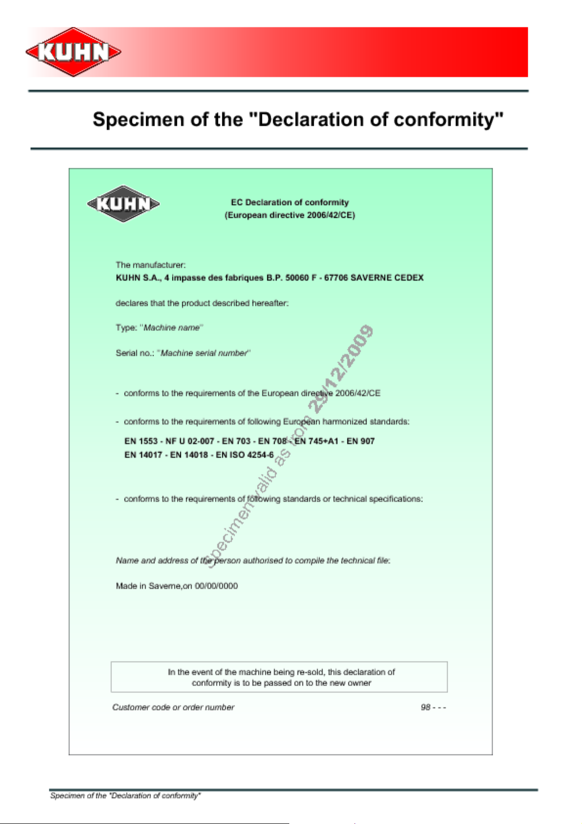
Page 95

Page 96

 Loading...