

Page 1
Operatio n manual
Issue 5/2009
Date of printing 6.2009
Language EN
Ex machine no. (PIN) VGTH222624
Serial number (PSN) 67TH01
Reference No. ZNA016EN
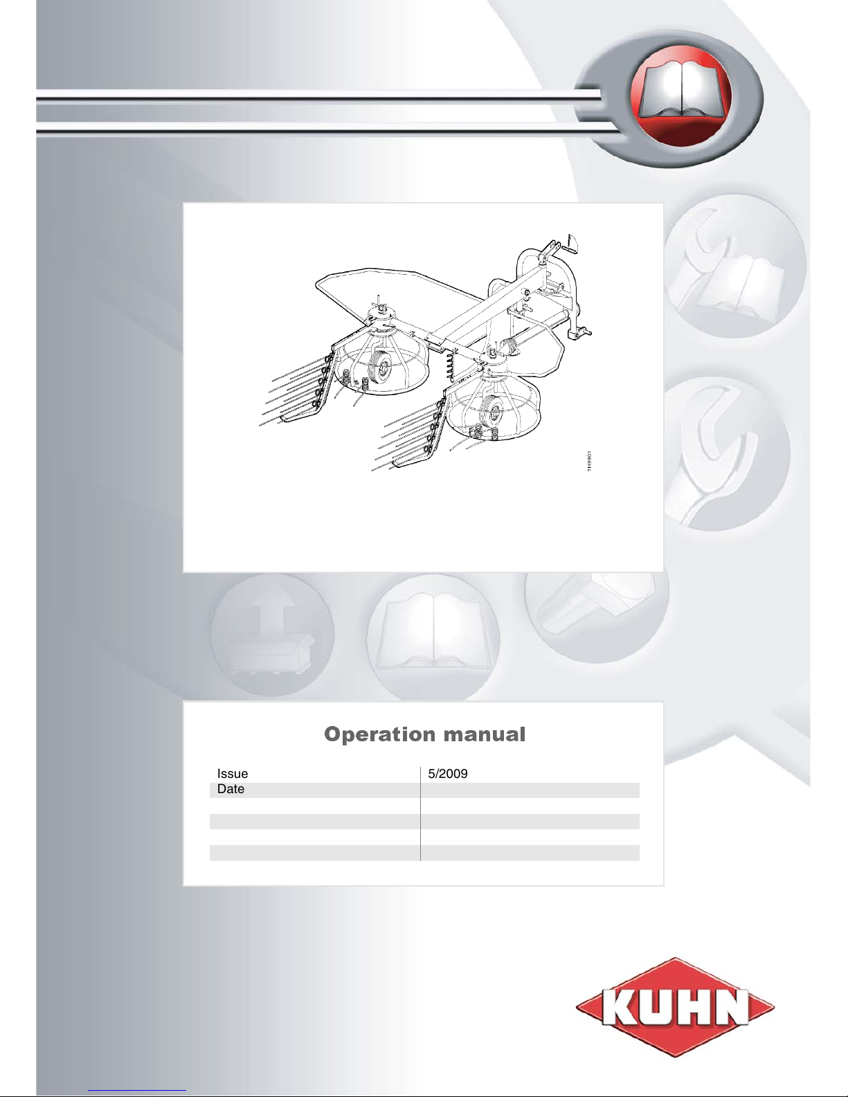
HAYBOB 300
Page 2

Identifica tion of the m achi ne
To support you as soon as possible your dealer requires several details of your machine.
Please enter the details here.
Designation
PIN
Software
version
Accessories
Address of
dealer
Address of
manufacturer
KUHN-GELDROP BV retains all copyrights and rights of usage. The contents of this operating manual are subject to change without notice. All
rights reserved. The right to technical revision is reserved.
HAYBOB 300
VGTH....................
KUHN-GELDROP BV
Nuenenseweg 165
5667 KP Geldrop
The Netherlands
Phone +31 40 2893300
Page 3

Table of contents
3
Table of contents
Preface............................................................. 4
Used terms and symbols ...............................5
General 5
Destination and intended use ....................... 6
General 6
Safety and reliability .......................................7
Safety instructions 3-point rotary hay
making machines 7
Safety and reliability .....................................12
Tractor loads 12
Pre-operation ................................................15
Attachment to the tractor 15
Transport 15
Operation .......................................................16
General instructions for use 16
Maintenance ..................................................20
General 20
Torque values for international metric
thread joints 22
Conversion table for units of measurement 24
Maintenance ..................................................25
Optional equipment ......................................26
EC Certificate of conformity ........................ 27
Index ..............................................................28
Page 4

4
Preface
Preface
The range of your machinery has now been improved which
incorporates the latest developments in hay making. It is a first class
engineering product backed by a widespread distributor/dealer
organisation to give you an efficient after sales service.
This machine shall be exclusively used for the normal agricultural
work as described in section "Destination and intended use" on page
6.
In this context we want to draw your special attention to “Preoperation” on page 15 and to the “Safety Decals” on page 10.
You will find all illustrations of the operation manual on the fold-out
page at the very end.
This manual has been prepared to enable you to obtain the best
results from your machine. Please read it carefully and follow the
instructions. Your dealer will be pleased to help if any problems arise.
Please keep this manual for reference. Fill in the receipt of delivery,
send it to your dealer and keep the copy well. Enter the machine
number (PIN) you find on the identification plate of the machine in the
frame on page 2 of this manual: it is important in case of any service
contact and when ordering parts, etc.
Page 5
Used terms and symbols
5
Used terms and symbols
General
Specifications are subject to change without previous notice.
Directional indications such as 'right', 'left', 'front' and 'rear', etc. are to
be interpreted when facing in direction of travel.
Parts are numbered from left to right.
This is also the basic position for defining the direction in connection
with which:
- rh (rotation) = clockwise rotation
- lh (rotation) = counter or anti-clockwise rotation
Rotation around a vertical axis is defined when looking from top to
bottom.
Rotation around a horizontal axis almost perpendicular to the direction
of travel is defined when looking from the left to the right.
Rotation of bolts, nuts, hand cranks, etcetera is defined when looking
from the position of operation.
Units of measurement are given both in Imperial/US and international
metric units; the metric value shall be decisive.
Abbreviations used are:
* = you can find this numbers on the identification plate of the machine.
DANGER:
When you see this safety alert heading be alert to the danger of injury
of death of men and animals!
Attention:
When you see this heading, be alert to the possibility of damage to
equipment, crop, buildings, etc., but to financial and/or juridical
problems (warranty, product liability) as well!
This heading indicates a remark to make a job easier, better and safer.
Abbreviation Explanation
cw clockwise
ccw counter-clockwise, anti clockwise
IPL IIlustrated spare Parts Lists
IPB Illustrated Parts Book
PIN* Product Identification No.
PSN* Production Series Number
Page 6

6
Destination and intended use
Destination and intended u se
General
This machine is exclusively appropriate-designed for raking,
spreading and tedding of loose plant parts, mainly cut grasses and
herbs for agricultural forage production, taking into account all
prescriptions, procedures, etcetera as stated herein.
This machine shall be exclusively used for normal agricultural work.
Attention:
Any use beyond the one stipulated above requires written
authorization of the manufacturer; refer also to the reliability and
warranty chapter in this manual!
Technical spe cific ati ons
Machine type HAYBOB 300
Machine code TH
Working width: 300 cm
Transport width 280 cm
Height 125 cm
Distance lower tractor links - gravity point 120 cm
Weight (mass) 300 kg
Lubrication points 2 (except PTO drive shaft)
Rotors 2
Double tines 20
Tyres 15x6.00-6 (4PR)
Tyre pressure 1.5 bar
Drive:
- PTO speed 350 - 540 rpm
- PTO drive shaft with slip clutch (700 Nm)
PTO drive shaft with slip clutch, 730 Nm (539 ft-lb)
Linkage cat. I and II
Page 7

Safety and reliability
7
Safety and reliability
Avoid accidents! Don't learn safety the hard way! Stay alert!
Think SAFETY! Work SAFELY!
Prior to operating the machine read and observe this operation
manual and all safety instructions and decals
Everyone must be given operating instructions before starting to
operate the equipment. Pass on all safety advices also to other users!
Safety instructions
3-point rotary hay
making machines
General
You are responsible for the SAFE operation and maintenance of your
equipment. It is the operator's responsibility to read and understand
ALL safety and operating instructions in the manual and to follow
these. You must ensure that you and anyone else who is going to
operate, maintain or work around the unit be familiar with the
operating and maintenance procedures and related SAFETY
Information contained in this manual. The manual will take you stepby-step through your working day and alert you to all good safety
practices that should be adhered to while operating this equipment.
Remember, you are the key to safety. Good safety practices not only
protect you but also the people around you. Make these practices a
working part of your safety programme. Be certain EVERYONE
operating this equipment is familiar with the recommended operating
and maintenance procedures and follow all safety precautions. Most
accidents can be prevented.
Do not risk injury or death by ignoring good safety practices.
• Machines must never be tested on a tractor in an enclosed space
because of the danger form exhaust fumes!
• Always check traffic and operational safety before any putting the
machine into operation!
• Adhere to the general rules of health and safety precautions
besides the advice of this manual!
• The installed warning and advisory signs give important hints for a
safe operation; adhering to serves your own safety!
• When making use of public roads adhere to applicable traffic rules!
• Become acquainted with all installations and control devices as
well as with their function before beginning the operation. Doing
this during operation would be too late!
• The clothing of the operator should be tight. Avoid wearing any
loose clothing!
• Before beginning to drive and/or operate check surrounding area
(children!). Ensure sufficient visibility during all operation and
transport!
• Nobody shall ride on the machine during transport and/or
operation!
• Attach accessories in accordance with mounting instructions and
only to the appropriate attaching points!
• Special care shall be taken when (dis)mounting the machine on/off
the tractor!
• When attaching/detaching the machine place the jack stand into
Page 8

8
Safety and reliability
the corresponding position!
• Always fit front weights to the fixing points provided for that
purpose.
• Adhere to maximum permissible axle loads, total weights and
transport dimensions!
• Install and check transport equipment, e.g. lighting, warning
devices, guards!
• For road transport bring machine in a transport position and secure
it!
• Never leave the operator's seat during operation or transport.
• Moving behaviour, steerability and braking performance are
influenced by mounted implements and ballast weight! Ensure
sufficient braking effect and safe manageability!
• Always adapt the speed to the local conditions! When making short
turns note the larger radius because of increased width and/or
length of the combination as well as mass and inertia changes due
to the other center of gravity position!
• Do not operate a machine unless all protection is installed and in
functional position!
• Never stay or allow anyone to stay within the operating area!
• Never stay or allow anyone to stay within the turning and slewing
area!
• Before leaving the tractor lower the machine onto the ground,
apply the parking brake, shut down the engine and remove the
ignition key!
• Allow nobody to stay between tractor and machine unless the
tractor is prevented from inadvertent rolling away by applied
parking brake and or placed chocks!
• Before (un)hitching the machine on the three-point linkage set the
controls in a position that prevents from inadvertent lifting/lowering!
• Ensure hitching category of machine corresponds to tractor: adapt
if required!
• Keep clear of three-point linkage area: danger of crushing and
scissoring!
• Do not stand between tractor and machine when handling the
external three-point linkage controls!
• Always use stabilizers or check chains to prevent sideways
movement of the machine, especially during transport!
• During road transport the three-point linkage control lever must be
secured against lowering!
• The protection of the machine prevents from penetrating into
danger areas! Therefore all protection must be kept in optimal
condition and moved into the functional position prior to starting to
work!
• Before performing any work on the machine ensure the tines have
stopped all rotation, shut down the engine and remove the ingition
key!
DANGER:
Machine continues rotation due to inertia: wait until tines really stand
still.
Page 9

Safety and reliability
9
• Do not modify the equipment in any way. Unauthorised
modifications may impair the function and/or safety and could
affect the life of the equipment!
• Repair damages prior to next operation.
Drive through un iv ersa l
joint drive sh afts
• Only use universal joint drive shafts complying with the
specification of the machine manufacturer for that specific use!
DANGER:
In order to ensure protection of both man and machine excise extreme
caution when working at a universal joint drive shaft other then
described in this manual and/or on the instruction at the instruction at
the univ. joint drive shaft. Modification of and other special jobs on
universal joint shafts require written explicit order and procedure of
both machine and univ. joint drive shaft manufacturer is available!
Use the correct tools and genuine parts to ensure the right
performance and max. safety (also see Reliability and Warranty
section 1.2)! This also in accordance with the EU-safety prescriptions
of the Machine Directive 89/392/EU!
• Externally accessible univ. joint drive shafts (e.g. PTO drive shafts)
as well as tractor PTO and machine input shaft must be equipped
with appropriate guards and cones! All the parts shall be kept in a
proper condition!
• Univ. joint drive shaft guard tubes shall overlap sufficiently (and as
safely advised) in all transport and working positions!
• Do not (dis)connect or work on a univ. joint drive shaft unless the
engine has been shut down and stopped and the ignition key has
been removed!
• Ensure univ. joint drive shaft is connected correctly and safetied by
the lock!
• Prevent shaft guard from spinning by attaching the safety chain(s)
to a static part (e.g. not used top link hole).
• Prior to engaging or switching on the PTO ensure nobody stays in
the danger area of the machine!
• Do not engage or switch on the PTO while engine is stopped!
• Prior to engaging or switching on the PTO ensure the PTO speed
cannot exceed 540 rpm!
• When working with PTO drive do not allow anyone to stay near any
spinning univ. joint drive shaft!
• Always stop PTO when it is not needed and when the max.
universal joint angle might be exceeded.
DANGER:
After disengaging or switching off the PTO, the PTO driven machine
will continue running because of inertia! Keep a safe distance to the
machine untill the tines really stand still: the fast rotating tines are
invisible for men's eye!
• Do not clean and/ord grease the PTO driven machine and
universal joint drive shafts unless PTO and engine have stopped
and the inginiton key has been removed!
• Place the uncoupled PTO drive shaft on the retaining device
provided!
Page 10

10
Safety and reliability
• After removal of PTO drive shaft place protective cover/cap
over PTO!
Wheels an d tyres
• When working on the wheels make sure that the machine has been
placed on the ground safely (jack stand) and that it is secured by
chocks against unintentional rolling!
• Mounting wheels and tyres requires sufficient knowledge and
availability of prescribed tools and equipment being in perfect
condition; repairs on tyres may only be performed by trained staff
with suitable tools!
• Check air pressure regularly: ensure prescribed value!
Safety Decals
Attention:
Good safety practice requires that you become familiar with the
various safety decals, the type of warning and the area, or particular
function related to that area, requiring your SAFETY AWARENESS!
Attention:
This machine has been marked with safety decals of the new
generation in acc. with ISO11684, i.e. without text. The decals are
shown below!
TR2005
Stop the engine and ensure it cannot be re-started during performance
of work on the machine!
TR2011
When three point linkage is controlled from outside ensure nobody is
between tractor and machine!
Storage safety
• Store the unit in an area away from human activity.
• Do not permit children to play on or around the stored unit.
• Use the provided jack stand supports, store in stable machine
mode.
Page 11

Safety and reliability
11
Liabili ty and w arran ty
In order to ensure safety all persons working at and/or with this
machine must read and understand this operation manual.
Furthermore this machine shall always be used, handled and stored
in accordance with the design and construction destination (intended
use) which also means:
• Exclusively work in accordance with the instructions given in the
appropriate Assembly, Operation and Repair Instructions
(manuals) including all valid Errata and Supplements as well as
taking into account the relevant Service Bulletins; exclusively use
correct tools and equipment being in a perfect condition!
• Strictly observe the applicable local regulations concerning safety
and accident prevention, generally acknowledged and approved
technical, medical and traffic rules as well as the functional
limitations and safety instructions stated in above mentioned
technical documentation!
• Do not use any parts (spares, accessories, lubricants) other then
those complying with manufacturer requirements. A part complies
with manufacturer requirements when either genuine or approved
by the manufacturer or when all its properties can be proven to
meet with the appropriate manufacturer requirements for that very
use/function!
• Only well instructed people being familiar with all possible danger
shall work with or at the machine!
• The machine shall not be used nor transported unless all safety
devices (covers, plates, rails, curtains, locks, etc.) are correctly
installed and in a perfect condition and set in the appropriate safety
position! All safety decals and signs shall be legible and in the
correct place!
• Unauthorised modification of or arbitrary changes on the machine
or parts of it exclude any responsibility and reliability of the
machine manufacturer for the consequences of that operation!
Attention:
Those disregarding above mentioned rules act grossly negligent
(careless) through which all manufacturers warranty and reliability for
damages and all other consequences become extinct. The negligent
person carries all risks!
Page 12

12
Safety and reliability
Safety and reliability
Tractor loads
Attention:
Obey the maximum permissible mass, permissible axle loads and
permissible tyre loads.
Attaching machines to the front or to the rear 3-point linkage may
never result in:
• Exceeding the maximum permissible mass.
• Exceeding the maximum permissible axle load.
• Exceeding the maximum permissible tractor tyre load.
• Not complying with the minimum front axle load.
• Not complying with the minimum rear axle load.
Check all m a xi m um
and mini m um l oad s
Before using the machine always check if the requirements as
mentioned above are met.
Most of the dimensions and masses in the figure at the left can be
found in the tractor manual or in the corresponding machine manual.
In case this data can not be found, contact the corresponding dealer
or measure or calculate this value.
Legend:
Actual total mass
The actual total mass can be determined by:
• weighing.
• calculation:
This value may never exceed the maximum permissible mass.
F G
B CA
*
*
*
*
*
IH J
D E
Dimension Description Unit
A Unladen tractor mass kg
B Unladen front axle load kg
C Unladen rear axle load kg
D Total mass front attachment kg
E Total mass rear attachment kg
F Distance from the lower link ball point centre
to the front attachment’s centre of gravity
mm
G Distance from the front axle centre to the
lower link ball point centre
mm
H Tractor wheel base mm
I Distance from the rear axle centre to the
lower link ball point centre
mm
J Distance from the lower link ball point centre
to the rear attachment’s centre of gravity
mm
A + D + E = ........... kg
Page 13

Safety and reliability
13
Actual front axle load
The actual front axle load can be determined by:
• weighing.
• calculation:
The actual front axle load may never exceed the maximum
permissible front axle load.
The actual front axle load may never be less than the minimum front
axle load (M). In case the minimum front axle load (M) is not
mentioned in the tractor manual, the minimum front axle load (M) has
to be at least 20% of the unladen tractor mass (A).
In case the minimum front axle load is not met, you have to add front
ballast.
To calculate the minimum required front ballast:
Attention:
In case front ballast is mounted directly at the tractor, replace “F + G”
in the formula by the “Distance from the centre point of the front axle
to the gravity point of the ballast”.
Always check the maximum permissible mass, permissible axle load
and permissible tractor tyre load after mounting front ballast.
Actual rear axle load
The actual rear axle load can be determined by:
• weighing.
• calculation:
The actual rear axle load may never exceed the maximum permissible
rear axle load.
The actual rear axle load may never be less than the minimum rear
axle load (N). In case the minimum rear axle load (N) is not mentioned
in the tractor manual, the minimum rear axle load (N) has to be at least
45% of the unladen tractor mass (A).
In case the minimum rear axle load is not met, you have to add rear
ballast.
To calculate the minimum required rear ballast:
Attention:
In case the front ballast is mounted directly at the tractor, replace “F +
G” in the formula by the “Distance from the centre point of the front
axle to the gravity point of the front ballast”.
Always check the maximum permissible mass, permissible axle load
and permissible tractor tyre load after mounting rear ballast.
B +
D x (F + G + H)
H
-
D x (F + G +H)
H
= .......... kg
E x (I + J) - (B x H) + (M x H)
F + G + H
= .......... kg
C +
E x (H + I + J)
H
-
D x (F + G)
H
= .......... kg
D x (F + G) - (C x H) + (N x H)
H + I + J
= .......... kg
Page 14

14
Safety and reliability
Actual tyre load
The actual tyre load can be found by dividing the corresponding actual
axle load by 2.
The actual tyre load may never exceed the maximum permissible tyre
load.
Attention:
The maximum permissible tyre load is depending on the tyre pressure
and the driving speed.
Page 15

Pre-operation
15
Pre-operation
Attach me nt to th e
tractor
Since the hitch brackets are reversible, the hitch frame is suitable for
both cat. I and II.
- Cat. I: small diameter pins on the outside.
- Cat. II: large diameter pins on the outside.
Prior to attaching the machine to the tractor, ensure the draft links are
on equal level!
If necessary the PTO drive shaft between the tractor and machine
should be shortened to prevent damage when it is in its shortest
position.
> Check the length of the PTO drive shaft, shorten the drive shaft if
necessary.
Care must be taken to ensure the PTO drive shaft is not shortened too
much, see the instructions that come with the PTO drive shaft.
Always use stabilisers or check chains when attaching the machine to
the tractor, to prevent sideways movement of the hitch frame
damaging the pto drive shaft.
Dependent on the length of the top link, either the front or the rear hole
in the hitch frame can be used.
Transport
Set machine as follows:
> Lift and secure jack stand (1) (if jack had been lowered before).
> Lower machine and start a rh turn. Then pull up and engage lever
(2) under bracket pin (3) from tractor seat using cord (4).
> Ensure both deflectors (5) are positions max. inward and secured;
lift machine to transport position.
Page 16

16
Operation
Operatio n
General instructions
for use
To enable the machine to follow ground contours correctly, the
hydraulic lift lever should be in float position during work, so that the
lift arms can move freely up and down.
For a good action, the speed of the PTO should be between 400 and
540 rpm depending on the circumstances. This prevents excessive
wear, limits leaf losses and reduced crop pollution.
To limit the working angle of the PTO drive shaft, it is advisable to
make left-hand turns only, especially when raking.
Always make sure that the tines have been fitted correctly.
Adjustme nts for spreading
and tedding
> Lower machine and start a rh turn.
> Then pull cord (4) to disengage lever (2) from bracket pin (3).
> Set all tines to tedding position (6).
> Use the lower holes (7) for wheel height adjustment: to avoid strips
being left between the rotors (e.g. in a short and difficult crop) it is
advisable to use a higher hole.
Page 17

Operation
17
> Then lower machine completely and drive a little forward, until the
centre slot at front of hitch frame appears clearly visible (arrow,
fig.).
In this position the forward side of the rotors is nearest the ground.
> Now operate machine at full working speed (350-540 rpm at the
pto) and adjust top link, so that the tine tips are just touching the
stubble in front of the rotors.
Forward inclination of rotors can be set as required for the
circumstances by varying wheel height in conjunction with top link
length!
To prevent the crop being moved too far to the side, especially when
working around the boundary of the field, the tedding width of the
machine can be restricted by the deflectors (5) which can be set
laterally, using stays (8).
Each deflector (5) also can be set into two vertical positions by rotating
the nylon blocks (11) through 180°. Use the upper position under
abrasive conditions.
Page 18

18
Operation
Adjustme nt for raki ng
> Lower machine and start a rh turn.
> Then pull cord (4) to disengage lever (2) from bracket pin (3).
> Set all tines to raking position (9).
> Use the upper holes (10) for wheel adjustment. In long stubbles the
use of the lower holes can be advantageous for better pick-up and
clean raking.
> Lower machine completely and drive a little forward, until the
centre slot at front of hitch frame appears clearly visible (arrow,
fig.).
In this position the forward side of the rotors is nearest the ground.
> Now operate machine at full working speed (350-540 rpm at the
pto) and adjust top link, so that the tine tips are just touching the
stubble in front of the rotors.
Forward inclination of rotors can be set as required for the
circumstances by varying wheel height in conjunction with top link
length!
Page 19

Operation
19
> Set deflectors as required using stays (8).
Always make certain that the distance between the deflectors is large
enough, especially in a heavy crop to prevent material from being
pulled out of the swath. When you place the deflectors as shown in fig.
the swaths are laid down close together in the first operation. These
swaths are easily put together afterwards.
Each deflector also can be set into two vertical positions. This can be
achieved by rotating the nylon blocks (11) through 180°. Use the upper
position under abrasive conditions.
Page 20

20
Maintenance
Maintenance
Attention:
Warranty and liability claims of damages caused by inadequate
maintenance (e.g. insufficient lubrication) will be rejected!
General
After a few hours of a new or overhauled machine check that all nuts
and bolts are tight. Special attention should be paid to those holding
the tines and bolts securing the rotors, located under the top of the
rotors. Recheck regularly.
Tines
The HAYBOB 300 has 4 different tines
• 'PZ 107E' (5x) = lh, narrow
• 'PZ 110E' (5x) = lh,wide
• 'PZ 224E' (5x) = rh, narrow
• 'PZ 225E' (5x) = rh, wide
Above mentioned tines are Super C quality tines. The cheaper and
lower quality "B"-tines can be obtained by adding an "E" to the part no.
(e.g. PZ107E).
Always ensure that these tines have been fitted correctly, for example:
• The blue marked tines on the left-hand rotor, the yellow marked
tines on the right-hand rotor.
• Narrow and wide alternately fitted.
• Short finger to the top, long finger to the bottom.
• The bend of the tine should be pushed close to the attachment bolt
(see arrow).
Page 21

Maintenance
21
Lubrication
Attention
Always use a good and adhesive multi-purpose grease for lubrication
of both machine and PTO drive shaft!
The following points need the attention:
• Machine
• PTO drive shaft
Attention
Ensure profiles tubes of pto drive shafts are well greased at all times!
Check a new or repaired machine and/or drive shaft prior to first run
and then every 20 working hours!
Also ensure sliding surfaces of the protection tubes are greased!
Page 22

22
Maintenance
Torque values for
international metric
thread joints
All bolted joints on this machine must be torqued in accordance with
the values given in this table below unless indicated otherwise (e.g. in
Parts List or Installation Instruction, etc.)
On this machine 8.8 is both standard and minimum quality used. If not
indicated anyhow use this quality for determination of torque (in most
cases the quality can be found on the head of the respective bolt).
* Material quality in acc. with DIN ISO 898.
** Value in brackets means inch-pounds (in-lb).
*** Size of jaw of lock bolts and nuts with toothed flange are given
(metric values only) in brackets if different from standard.
• The listet values are applicable for dry or slightly oiled joints.
• When a stiff grease is applied decrease the given value by 10%.
Do not use plated bolts/screws/nuts without grease.
• In case lock nuts, lock screws or lock bolts are used the given value
has to be increased by 10%.
• Torque value of wheel nuts M18x1,5 shall be 270 Nm (200 ft-lb)!
Thread Torque value Size of jaw***
8.8* 10.9* 12.9*
Nm ft-lb** Nm ft-lb** Nm ft-lb** mm inch
M3 1.3 (11.5) 1.8 (16) 2.1 (18.6) 6 7/32
M4 2.9 (25.5) 4.1 (36.5) 4.9 (43.5) 7 9/32
M5 5.7 (50.5) 8.1 (71.5) 9.7 (86) 8 5/16
M6 9.9 7.3 14 10.3 17 12.5 10 13/32
M8 24 17.7 34 25 41 30.3 13 33/64
M10 48 35.4 68 50.2 81 59.8 17 (15) 11/16
M12 85 62.7 120 88.6 145 107 19 (17) 3/4
M14 135 99.6 190 140 225 166 22 (19) 7/8
M16 210 155 290 214 350 258 24 (22) 1 21/128
M18 290 214 400 295 480 354 27 1 9/128
M20 400 295 570 421 680 502 30 1 3/16
M22 550 406 770 568 920 679 32 1 17/64
M24 700 517 980 723 1180 871 36 1 27/64
M27 1040 767 1460 1077 1750 1291 41 1 79/128
M30 1410 1041 1980 1461 2350 1734 46 1 13/16
M33 1910 1410 2700 1996 3200 2362 50 1 31/32
M36 2450 1808 3450 2546 4150 3063 55 2 11/ 64
M39 3200 2362 4500 3321 5400 3985 60 2 3/8
Page 23

Maintenance
23
Tensile strength Material quality acc. to DIN ISO 898
8.8 10.9 12.9
up to and incl. M16 over M16
N/mm
2
808 830 1040 1220
lbf/sq.in. 117,222 120,414 150,880 176,994
Page 24

24
Maintenance
Conversion table for
units of measurement
Length
1m 1000 mm 39 3/8 in 3.2809 ft
1 mm 0.03937 in 5/128 in
1km 3280.9 ft 0.6214 mi 0.5396 NM
1 mi 1.6093 km 1609.3 m
1NM 1.8532 km 1.1515 mi 6080 ft
1yd 36in 3ft 0.914m
1in 1” 25.4 mm 0.0833 ft 1/12 ft
1 ft 1’ 12 in 304.8 mm 30.48 cm
Area
1m² 0.01 a 10.764 sq.ft.
1 a 100 m² 1076.4 sq.ft.
1ha 100 a 2.47 acre
1acre 0.4ha
Volume
1m³ 1000 dm³ 35.3 cu.ft.
1 dm³ 1 l 1.057 US qt(fl) 0.88 Imp.qt.
1cu.in. 16.387 cm³
1 cu.ft. 28.317 dm³
1 Imp.bu. 8 Imp.gal. 36.368 l
1 US bu 8 US gal(dry) 9.308 US gal(fl) 35.232 l
Force and weight
1N 0.102 kg(f) 0.22487 lb(f)
1 kg(f) 9.8 N 2.2046 lb(f)
1lb(f) 4.4447 N
Pressure and tension
1 bar 1.02 at 0.987 atm 14.5 psi 100 kPa
1psi 0.0689 bar 6.89 kPa
Page 25

Maintenance
25
Maintenance
Torque
1Nm 1J 0.102 kg(f)m 1Ws 0.738 ft-lb(f)
1 ft-lb(f) 1.356 Nm 12 in-lb(f)
1in-lb(f) 0.113 Nm
Power
1kW 1000 W 0.738 ft-lb(f)/s 1.359 pk 1.359hp
1 pk 1 PS 1 cv 1 cf 0.73575 kW
1hp 0.73575 kW
1 Btu/h 0.2930 W
Speed of rotation
1rpm 1/min 1/60 Hz
1Hz 1cps 1/s 60rpm
Forward speed
1km/h 0.27778 m/s 0.6214 mph 1kph 0.9113 fps
1 mph 1.609 km/h 0.4470 m/s 1.466 fps
Page 26

26
Optional equipment
Optional equipment
Parts listed below can be standard equipment in your area: contact
your dealer.
Install in accordance with the assembly/installation instructions of the
respective option.
Install in accordance with the assembly/installation instructions of the
respective option.
For spare parts see IPL.
Instructions for ordering
spare parts
Your order for spare parts should contain the following information:
• Machine type and product identification number (PIN) or the PSN,
• Description, part number (see IPL) and quantity in question.
If in doubt send a rough sketch of the part clearly marked with your
name and address.
Attention
Take into account valid Errata and other supplements!
Guards (complete)
Part no. ‘VGTH00267K0’
Tine saver
Part no. ’VGGZ280V’ 20 each required (not shown)
Set of lamp supports
Part no. ‘VGRT00133’ (not shown)
You may require 3 sets, depending on your local regulations.
Page 27

EC Certificate of conformity
27
EC Certificate of confor mity
Conformin g to EE C
Directive 89 /3 92
We
KUHN-GELDROP B.V.
Nuenenseweg 165
NL-5667KP Geldrop
The Netherlands
declare in sole responsibility, that the product
to which this certificate relates, conforms to the basic safety and
health requirements of the Directives 89/392/EEC (amended with 91/
368/EEC, 93/44/EEC and 93/68/EEC) and 98/37/EC.
To effect correct application of the safety and health requirements
stated in the EEC Directives, the following standard(s) and/or
technical specification(s) has (have) been respected:
• EN292
• EN294
KUHN-GELDROP B.V.
Geldrop, 08-05-2009
Anthony van der Ley
General Manager
Rotary Hay Making Machine HAYBOB 300 and accessories
Page 28

Index
28
Index
A
Adjustments for raking 18
Adjustments for spreading and tedding
16
Attachment to the tractor 15
D
Destination and intended use
General
6
Technical specifications 6
M
Maintenance
Conversion table for units of measurements
24
General 20
Lubrication
21
Tines
20
Torque values for international metric thread
joints
22
O
Operation
Adjustments for raking 18
Adjustments for spreading and tedding
16
General instructions for use
16
Optional equipment
Guards (complete)
26
Instructions for ordering spare parts
26
Set of lamp supports 26
Tine Saver
26
P
Pre-operation
Attachment to the tractor
15
S
Safety and reliability
Drive through universal joint drive shafts
9
General
7
Liability and warranty 11
Safety decals
10
Storage safety
10
Tractor loads 12
Wheels and tryres
10
T
Technical specifications 6
Tines 20
Tractor loads
12
U
Used terms and symbols 5
W
Wheels and tyres
Safety and reliability 10
 Loading...