

Page 1
ASSEMBLY / OPERATORS
MANUAL
FRONT MOUNTED MOWER
GMD 602 F - GMD 702 F - GMD 802 F
N° 95006 C.GB - 06.2001
Page 2

DEAR OWNER,
In buying a KUHN machine you have chosen wisely. Into it have gone years of thought,
research and improvements. You will find, as have thousands of owners all over the world, that
you have the best that engineering skill and actual field testing can produce. You have
purchased a dependable machine, but only by proper care and operation can you expect to
receive the performance and long service built into it.
This manual contains all the necessary information for you to receive full efficiency from your
machine. The performance you get from this machine is largely dependant upon how well you
read and understand this manual and apply this knowledge. Please DO NOT ASSUME THAT
YOU KNOW HOW TO OPERATE AND MAINTAIN YOUR MACHINE before reading this
manual carefully. KEEP THIS MANUAL AVAILABLE FOR REFERENCE.
Your KUHN dealer will instruct you on the general operation of your machine. He is interested
that you get the best performance possible and will be glad to answer any special questions
that may arise regarding the operation of the KUHN machine.
Your KUHN dealer can offer a complete line of genuine KUHN service parts.
These parts are manufactured and carefully inspected in the same factory that builds the
machine to assure high quality and accurate fitting of any necessary replacements.
When ordering service parts it is important that you indicate the type of machine concerned
and its serial number.
For this reason please complete the model identification plate diagram below with the required
information. This will provide you with an easy reference for future service parts orders.
ABOUT IMPROVEMENTS
KUHN is continually striving to improve its products and, therefore, reserves the right to make
improvements or changes when it becomes practical to do so, without incurring any
obligations to make changes or additions to the equipment sold previously.
Page 3

- 1 -
CONTENTS
Page
Safety notices 2
Safety decals 8
Technical specifications 10
Signalling elements 11
Tractor front hydraulics requirement 12
Adapting the mower to the tractor 13
Transporting the mower 19
Working position 20
Using the mower 21
Adjustments 22
Detaching the mower 23
Lubrication 24
Maintenance 28
Inspection of knives & securing elements 30
Storing the mower 32
Optional equipment 32
Trouble shooting guide 33
Limited warranty 34
Copyright 2001 KUHN S.A.
Page 4

- 2 -
SAFETY
The above symbol is used throughout this manual every time recommendations are made concerning your safety,
the safety of others, or the good operation of the machine.
These recommendations must be made known to all machine operators.
DESIGNATED USE OF THE MACHINE
The GMD 602 F - GMD 702 F - GMD 802 F front mounted mowers must only be used for the work which they have
been designed : mowing on the ground of hay fields, grass silage fields and improved pastures for the purpose of
harvesting fodder for feeding livestock.
The manufacturer is not held liable for any damage resulting from machine applications other than those specified
by the manufacturer.
Any use other than the designated operation is at the risk and responsibility of the operator.
Designated use of the machine also means :
- following operation, maintenance and repair recommendations given by the manufacturer ;
- using only genuine spare parts, equipment and accessories as designated by the manufacturer.
The GMD 602 F - GMD 702 F - GMD 802 F front mounted mowers must only be operated, maintained and repaired
by competent persons who are familiar with machine specifications and operation and are aware of any danger
involved.
The operator must imperatively respect current legislation concerning :
- accident prevention,
- work safety,
- public traffic circulation.
All safety advice indicated on the machine must be strictly observed.
The manufacturer is not held liable for any damage resulting from machine modifications carried out by the operator
himself or by a third party without previous written agreement from the manufacturer.
GENERAL SAFETY RECOMMENDATIONS
Before operating the machine, always ensure that tractor and machine are in accordance with work safety and road
traffic regulations.
Page 5

- 3 -
BASIC PRINCIPLES
1. In addition to the recommendations given in this manual, legislation on work safety and accident prevention must
also be respected.
2. Advice is indicated on the machine, specifying safety recommendations in order to prevent accidents.
3. Before travelling on public roads, the operator must ensure that the machine conforms to road traffic regulations.
4. Before starting work, the operator must be familiar with all machine controls, handling devices and their
functions. Once at work, it is too late to do so !
5. Do not wear loose clothing which could become caught up in moving elements.
6. Use a tractor equipped with a safety cab. Keep windows and roof hatch closed for reduced sound level while
operating the PTO driven implement.
7. Before starting up the machine and beginning work, check the surrounding area (beware of children !). Make
sure there is sufficient visibility. Keep all people and animals away from the danger zone of the machine (risk
of projection!)
8. Carrying people or animals on the machine when working or in transport is strictly forbidden.
9. Machine must only be attached to tractor using means provided and in accordance with current safety
standards.
10. When attaching or removing the machine, place the parking stand into the corresponding position.
11. Special care should be taken when attaching or removing the machine from the tractor.
12. Before attaching the machine, make sure that the maximum permitted front axle weight and gross weight of
the combination are not exceeded.
13. Do not exceed the maximum permitted length and width authorized by road traffic regulations.
14. Before transporting the machine on public roads, ensure that all legally required guards and indicators (lights,
reflectors ...) are in place and in good operation.
15. All operating controls (cords, cables, rods ...) must be positioned so that they cannot be set off accidently,
risking accident or damage.
16. Before travelling on public roads, put the machine into its transport position as instructed in this operator’s
manual.
17. Never leave the tractor seat while the machine is operating.
18. Drive speed must be adapted to ground conditions as well as to roads and paths.
Always avoid abrupt changes of direction.
19. Precision steering, tractor adherence, road holding and efficient braking are influenced by the type of implement,
weight, ballast of front axle, ground or road conditions. It is therefore of utmost importance to be cautious in
every given situation.
20. Be particularly cautious when turning corners, paying attention to machine overhang, length, height and weight.
Page 6

- 4 -
21. Before operating the machine, ensure that all safety guards are firmly in place and in good condition. If worn
or damaged, replace immediately.
22. Before operating the machine, check the tightness of all nuts and bolts, particularly on tool fixing elements
(blades, tines, knives, spades ...). Retighten if necessary.
23. Keep clear of the machine operating area.
24. WARNING ! Danger of crushing and shearing can exist when components are operated by hydraulic or
pneumatic controls.
25. Before leaving the tractor or before adjusting, maintaining or repairing the machine, turn off the engine, remove
the ignition key and wait until all moving parts have come to a complete stop.
26. Do not stand between the tractor and the machine unless the hand brake is tight and/or stops have been placed
under the wheels.
27. Before any adjustments, maintenance or repairs are carried out, ensure that the machine cannot be started
up accidentally.
ATTACHMENT
1. When attaching or removing the machine from the tractor, position hydraulic lift control lever in such a way that
it cannot be set off accidentally.
2. WARNING ! Danger of crushing and shearing can exist in the lifting zone of the 3-point linkage !
3. Do not stand between the tractor and the machine when operating the outer control lever of the lift mechanism.
4. In transport, the machine lift mechanism should be stabilized by tractor tie rods to avoid floatation and side
shifting.
5. When transporting the machine in the raised position, lock the lift control lever in place.
POWER TAKE-OFF
1. Use only the PTO shaft supplied with the machine or recommended by the manufacturer.
2. PTO guards must always be in place and in good condition.
3. Check for correct PTO overlap when at work and in transport.
4. Before attaching or removing the PTO shaft, disengage PTO shaft, turn off engine and remove ignition key.
5. If a primary PTO shaft is equipped with a slip clutch or a free wheel, these must be fitted on the machine PTO.
Page 7

- 5 -
6. Ensure that PTO shaft is always correctly fitted and locked into place.
7. Make sure guards are correctly in place and secured with the safety chains provided.
8. Before engaging PTO, ensure that PTO speed (rotational frequency) and direction are in accordance with
manufacturer's recommendations.
9. Before engaging PTO, keep all people and animals clear from the machine.
10. Never engage PTO shaft when tractor motor is turned off.
11. Never surpass the PTO angle recommended by the manufacturer.
12. WARNING ! Rotating elements can continue turning momentarily after PTO is disengaged. Keep clear until all
rotating elements are at a standstill.
13. When removing the machine, place PTO shaft on the supports provided.
14. Fit the safety cap on tractor PTO.
15. Replace any worn or damaged PTO guards immediately.
HYDRAULIC SYSTEM
1. WARNING ! Hydraulic system is under pressure (maximum working pressure : 200 bars / 2900 psi).
2. When fitting hydraulic motors or cylinders, ensure that connections have been made correctly, as per
manufacturer’s instructions.
3. Before connecting hoses to the tractor hydraulics, ensure that tractor and machine circuits are not under
pressure.
4. It is strongly recommended that the operator marks the hydraulic connections between tractor and machine to
avoid making a wrong connection. WARNING ! Functions could be reversed (for example : lift/lower).
5. Regularly check the hydraulic hoses ! In case of normal wear, replace the hydraulic hoses every 5 years.
Damaged or worn hoses must immediately be replaced .
When replacing the hydraulic hoses, make sure to use hoses with the specifications and quality recommended
by the manufacturer of the machine.
6. Should a leak be found, take all necessary precautions to avoid accidents.
7. Any liquid under pressure (particularly oil from hydraulics) can penetrate the skin and cause severe injury. If
injured, see a doctor immediately, there could be danger of infection.
8. Before any adjustments, maintenance or repairs are carried out, lower the machine, depressurize the circuit,
turn off the engine and remove ignition key.
Page 8

- 6 -
MAINTENANCE
1. Before checking for any machine malfunction and before adjusting, maintaining or repairing the machine,
disengage PTO, turn off engine and remove ignition key.
2. Check tightness of nuts and bolts regularly. Retighten if necessary.
3. If the machine is raised, prop it up in a stable position before carrying out any maintenance work.
4. When replacing a working part, wear protection gloves and only use standardized tools.
5. It is forbidden to discard any oil, grease or filters. These must be given to waste disposal organisations to protect
the environment.
6. Disconnect power source before any work is done to the electric system.
7. Check safety guards regularly, particularly those that are subject to wear. Replace immediately if damaged.
8. Spare parts used must be in accordance with specifications and standards as defined by the manufacturer. Use
only genuine KUHN parts !
9. Before any electric welding is carried out on tractor or attached machine, disconnect generator and battery
terminals.
10.Repairs on elements under pressure or tension (springs, accumulators etc.) must only be carried out by
competent persons with standardized equipment.
SPECIAL SAFETY RECOMMENDATIONS
1. Stay a safe distance away from the mower when discs are rotating.
2. For safe machine operation, it is imperative that cutting tools be fitted in accordance with the manufacturer’s
recommendations. Use only the tool outfit supplied with the machine.
3. Each time before using the mower, inspect condition of cutting elements (knives, discs). Replace any missing,
worn or damaged cutting elements immediately. Use only genuine KUHN spare parts.
4. To avoid creating dangerous out of balance forces, always replace missing, damaged or worn knives in pairs.
5. When replacing knives or discs, systematically inspect their securing elements as per the manufacturer’s
recommendations.
6. Regularly inspect the disc mower’s protection cover. Worn or damaged protection covers must be replaced
immediately.
7. Protection devices (such as guards, shields etc.) are intended to prevent stones, rocks or other foreign objects
from being projected. They also prevent access to the machine’s danger zones. Therefore, it is imperative that
protection devices are put in place and properly secured each time before using the machine.
Page 9

- 7 -
8. Crushing and shearing zones which could cause serious bodily injury when changing the machine from
transport to work position and vice versa may exist. To prevent possible injury, be extra careful when
maneuvering and ensure that everyone is at a safe distance away from the machine.
9. PTO drive to the mower must never be engaged unless the cutterbar skid shoes are in contact with the ground
and the protective cover is folded down.
10. Ground of the pastures to be mown must be free of foreign objects.
11. Even when the machine is used in accordance with it purpose, objects may be projected. It is therefore
imperative that everyone be kept away from the danger zone, that extra care be taken and that extra precaution
(such as safety indicators) be taken when mowing pastures alongside roads or near public areas (parks,
schools etc.).
12. Never mow in reverse.
13. When disengaging the PTO drive, moving parts continue to rotate for some time. Wait for all moving parts to
come to a complete stop before approaching the machine.
14. If an obstruction is hit, stop the tractor immediately, disengage PTO drive, turn off engine, remove ignition key
and wait for all moving parts to come to a complete stop.
Check the entire machine for any damage before resuming work.
15. It is strongly recommended to have your machine checked by your dealer after each season, especially blades
and discs and their fixing devices (nuts, bolts etc.).
Page 10
- 8 -
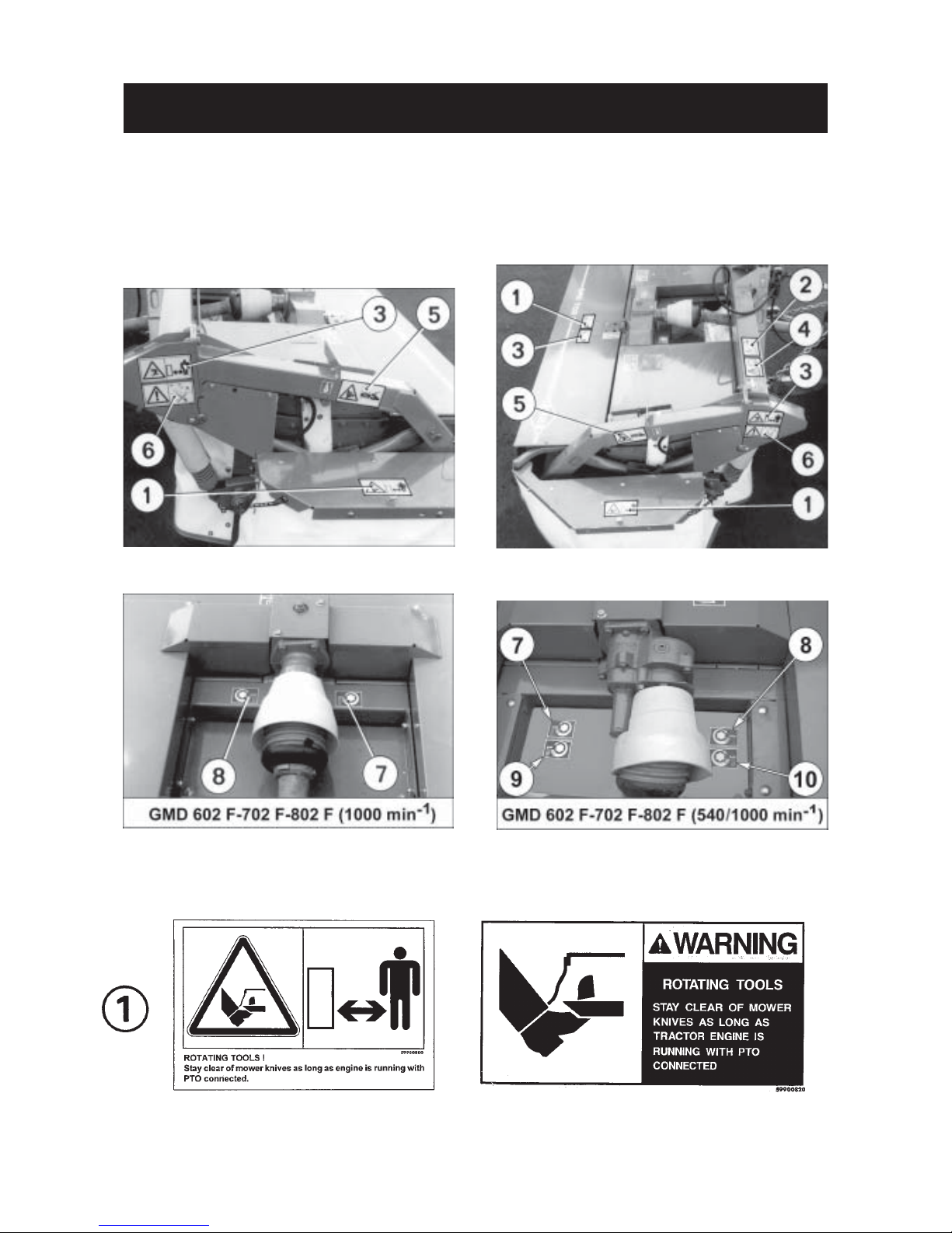
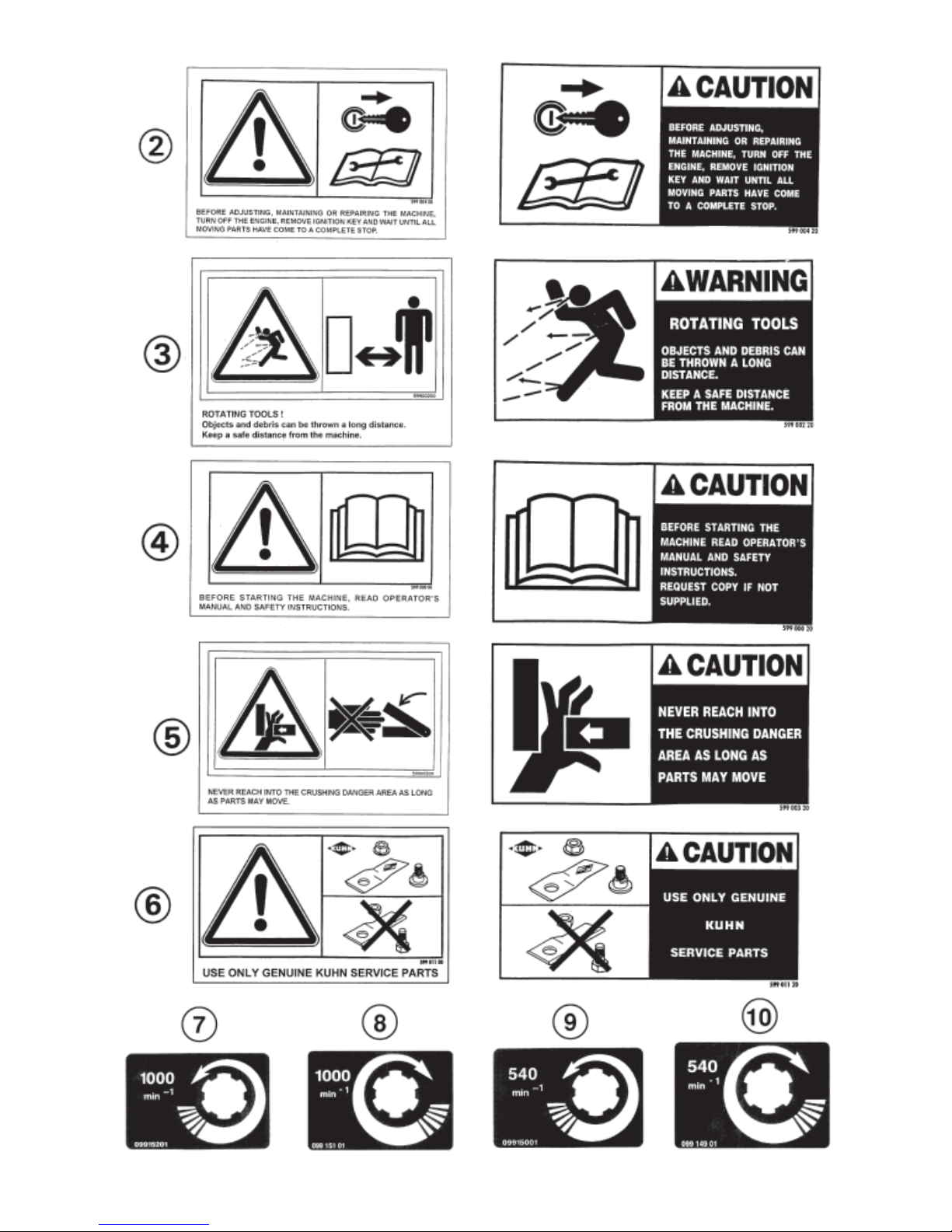
SAFETY DECALS
THE FOLLOWING SAFETY PICTORIALS HAVE BEEN PLACED ON YOUR MACHINE IN THE AREAS
INDICATED. THEY ARE INTENDED FOR YOUR PERSONAL SAFETY AND FOR THE SAFETY OF THE
PEOPLE WORKING WITH YOU. THE TEXT SHOWN ON THEM GIVES THEIR PRECISE MEANING.
ENSURE THAT THESE PICTORIALS ARE ALWAYS LEGIBLE. IF THEY ARE NOT, REPLACE THEM.
(OPTION)
Page 11
- 9 -
Page 12

- 10 -
GMD 602 F GMD 702 F GMD 802 F
Number of discs 6 7 8
Cutting width 2,40 m (7' 10") 2,80 m (9’ 2") 3,11 m (10' 2")
Transport width 2,25 m (7' 4") 2,66 m (8' 9") 2,99 m (9' 10")
Disc speed (rotational frequency) 3011 rpm (min-1) 3011 rpm (min-1) 3011 rpm (min-1)
Tractor PTO power requirement (as from) 31kW (42 hp) 36 kW (49 hp) 41kW (56 CV)
* PTO speed (rotational frequency)
(rotating clockwise or counterclockwise)
- GMD 602 F - 702 F - 802 F [1000 rpm (min-1)] 1000 rpm (min
-1
)
- GMD 602 F - 702 F - 802 F [540 / 1000 rpm (min-1)] 540 or 1000 rpm (min
-1
) (option)
Primary P.TO. shaft 1 3/8" 6 splines
Lift system hydraulic hydraulic hydraulic
Weight with PTO shaft (approx.) 735kg (1617 lbs) 805 kg (1771 lbs) 880 kg (1936 lbs)
TECHNICAL SPECIFICATIONS
* Adjustment from factory : rotating clockwise (seen in direction of travel)
Page 13

- 11 -
The GMD 802 F is standard equipped with a road signalling kit (no 107 6110).
For the GMD 602 F - 702 F the road signalling kit is available on option (see page 32).
Install the road signalling kit as described below :
- Fix the 2 signalling shields (1) on the supports (2) on each side of the machine with 6 hexagonal screws (3) (M
10 x 20), 6 self-locking nuts (M 10) and 2 flat iron bars (4) as shown on photo 2 (red corners must be facing upwards
and outwards).
- Fit pilot lights (5) to the front side of the reflector boards (1) (see photo 2).
- Fit the left tail light (6) identified by its white (shown in grey on figure A) connector terminal marked “L” to
the rear side of the left reflector board (photo 3).
- Fit the right tail light (marked “R” on its black connector terminal) to the rear side of the right reflector board.
- Layout the wiring harness using photos 2, 3 and 4 as a guide.The wiring harness is fixed on the frame with 4 clamp
collars and self-adhesive collar holders (7) and onto the hydraulic hoses with 9 clamp collars (8) (length 140 mm)
(photos 2, 3 and 4). Make sure to thread the wiring harnesses through holes (O) (photos 2 and 3).
Plug the harness connectors to the corresponding pilot and tail lamp terminals .The locking tab (12) of the
female connector (13) must be fully engaged over the peg (14) of the male connector (15) (fig. A).
- Attach electric plug support (9) to the main frame with an original hexagon bolt (10) (photo 2).
NOTE : - A 7 pin socket is required at the front of the tractor in order to switch on the signalling element lights.
- When parking the machine, place plug (11) in its support (9) on the frame (photo 3).
SIGNALLING ELEMENTS
A
2
4
3
Page 14

- 12 -
TRACTOR FRONT HYDRAULICS REQUIREMENT
5
PTO speed (rotational frequency) :
- 1000 rpm (min-1) to drive the GMD 602 F - 702 F - 802
F [1000 rpm (min-1)]
- 540 min-1 or 1000 min-1 to drive the GMD 602 F - 702
F - 802 F [540 / 1000 rpm (min-1)] (option).
Front hitch fitted with an A-frame, cat. 2 (ISO 11001).
The machine is supplied with a male hydraulic coupler
conforming to ISO 5676. The tractor is to be equipped
with a female coupler (O) connected in parallel with the
lift cylinders (photo 5) for simultaneous operation of the
front hydraulic lift cylinders and the machine headstock
cylinder.
When operating with a tractor equipped with a
double acting hydraulic lift, the spool valve must
be set in the detented fourth position (float position) to allow the cylinders to travel up and down
at will.
Page 15

- 13 -
ADAPTING THE MOWER TO THE TRACTOR
1) ATTACHING MOWER TO TRACTOR
- Mount the two hitch pins (T) on the lower yokes (I)
of the A frame (A) and secure them by means of the
roll pins (E) (diameter 8 x 45) (photo 6).
- Then attach the support chains (R) to the hitch pins
(T) using the bigger end link (photo 6). Secure them
with the lock plates (V) and linch pins (G) (photo 6).
- Lower the tractor front hydraulic lift and attach the
mower (photo 7).
- Connect the PTO shaft.
- Thread safety pin (S) through hole (6) of latch (4) of
triangular frame (A) (photo 7 and fig. 7 A).
Note : The safety pin (S) has a 4 mm diameter. If hole
(6) of the A-frame used is not big enough to
accomodate this pin, counter drill it to 4.5 mm.
Check that stop (3) of the triangular frame (A) is
adjusted correctly. For good operation this stop must
be positioned against latch (4) so that latch is still free
to pivot when pulling lever (5).
For adjustment, detach mower from the tractor and
proceed as follows :
- Untighten flush screw (2) so that stop (3) is free to
slide.
- Untighten lock nut of adjusting screw (1).
- Attach mower to the tractor.
- Rotate adjusting screw (1) until stop (3) contacts
latch (4).
- Check that latch (4) is free to operate by pulling lever
(5). If operation is difficult untighten screw (1) half a
turn.
- Detach machine from tractor.
- Tighten lock nut of adjusting screw (1) and tighten
flush screw (2).
Regularly check that stop (3) is adjusted correctly,
especially each time the mower is adapted to a new
A frame (A). Readjust if necessary.
6
7
Page 16

- 14 -
2) ATTACHING HYDRAULIC HOSE
Connect hydraulic hose (H) (photo 8) to tractor making sure that hydraulic cylinders are not under
pressure.
Check that the lever (L) is locked in place in the forward
notch (A) of the selector plate (photo 8A).
Lift the mower.
Using levers (K) fold back the transport locks (J)
towards the rear, keeping them in this position
(photo 9).
Attach both chains (R) to the highest possible
anchorage point on the tractor (photo 8). Chain length
is right if distance (Y) is at least 210 mm (8") (photo
9) when chains (R) are tight (photo 8).
9
8A
8
Page 17

- 15 -
3) DIRECTION OF ROTATION
Compare tractor PTO and direction of disc rotation.
OUTSIDE CONES MUST TURN INWARDS.
If the central gearbox (N) must be repositioned, proceed as follows :
- Lower the tractor hitch completely so that the ma-
chine rests on the ground.
- Remove the protector (O) (photos 10 and 10 A).
- Unscrew the 4 bolts (11) (M 12), remove the gearbox
(N) and the lateral PTO transmission shaft (photos
10, 10 A and fig. 11).
- Change over drain plug (12) and dipstick plug (13),
turn gearbox upside down. Reinstall gearbox in
place with the breather plug (13) facing upwards
(photos 10, 10 A and fig. 11)
- Tighten the four M 12 bolts (11) to 12 daNm (90 ft.lbs)
and reassemble all other components again.
4) PTO SHAFT
The PTO shaft is fitted with a 1 3/8 -6 spline yoke.
A 1 3/8-21 spline yoke can be ordered as an optional item under part No. 4603 187 for the GMD 602 F - 702 F - 802
F [1000 rpm (min-1)] and under part 4603 256 for the GMD 602 F - 702 F - 802 F [540/1000 rpm (min-1)].
a) GMD 602F-702F-802F [1000 rpm (min-1)]
Connect the PTO shaft (T) to the mower's central
gearcase (N) (photo 12) and to the tractor's 1000 rpm
(min-1) PTO stub.
10
12
10A
(OPTION)
Page 18

- 16 -
Make sure PTO shaft length is correct :
- When the PTO shaft is in its maximum extended position, a minimum tube overlap of 300 mm (12") must be
maintained.
- When the PTO shaft is in the maximum overlap position (retracted), tubes must not butt against the yokes.
A safety clearance (A) of 1 cm (1/2") must be maintained (fig. A).
b) GMD 602F-702F-802F [540 / 1000 rpm (min-1)] (option)
Connect the PTO shaft to the mower's central gearcase and to the tractor's 540 or 1000 rpm (min-1) PTO stub
(see photos 13, 14, 15 and 16).
PTO guard (P) must be mounted on the stub used to connect the PTO shaft (T) and the cap(C)
must be installed on the non used stub.
13
14
15
16
Page 19

- 17 -
If this is not the case, shorten the two transmission tubes and the two guard tubes by the same length (fig.
B and C).
Bevel and clean the transmission tubes (fig. D).
Grease the inside of the outer transmission tube (fig. E).
Never operate the PTO shaft at too great an angle (X) (+/- 30° maximum) (fig. 17).
17
D
Page 20

- 18 -
Failure to follow these basic PTO shaft adjustments will result in premature failure.
To avoid accidents which could be serious, make sure that guards are always correctly in
place and secured with the safety chains (photo 18 and 18 A). Damaged guards must be
replaced immediately.
18A
5) SAFETY CURTAINS
Before starting up the mower :
Make sure that all safety curtains are in the correct position.
19
18
Page 21

- 19 -
TRANSPORT
BEFORE TRANSPORTING THE MOWER ON PUBLIC ROADS, THE OPERATOR MUST ALWAYS
MAKE SURE THAT THE MACHINE CONFORMS TO THE LEGISLATION GOVERNING THE USE
OF AGRICULTURAL VEHICLES ON THE ROAD.
Before going on the road or transporting the mower from one field to another, proceed as follows :
- Check that the lever (L) is locked in place in the forward notch (A) of the selector plate (photo 8A, page 14).
- Activate the tractor hydraulic lift until the machine comes to a stop.
- Using levers (K) fold the transport locks (J) towards the front until engaged (photo 20 B).
- Using the box spanner (P) delivered with the machine, release the lock on the front protector (A) (photo 20).
- Pivot the 2 side protection flaps (B) towards the inside and lock them by lowering and engaging the front protection
flap (photo 20 A).
Slightly lower the mower to double check that the lock has latched in properly. The cutting unit and the headstock
must lower simultaneously.
When using public roads, employ at least one person to warn the driver of the vehicle of any
potential danger and give him indications to manoeuvre and travel safely, especially when
leaving the farm, on emerging roads and junctions.
20A
20B
20
20C
Page 22

- 20 -
WORKING POSITION
- Raise the machine.
- Using the box spanner (P) delivered with the machine, release the lock on the front guard (A) (photo 20).
- Using levers (K) fold the transport locks (J) towards the rear and lock them in place (photo 21).
- Pivot both side guard flaps (L) towards the outside in working position making sure to slide the tubes (T) in the
rectangular housings (E) (photo 22).
- Lock the side guard flaps (L) by lowering and locking of the front guard flap (A) (photo 21) and attach tensioners
(U) to the lower mounting yokes (I) of suspension springs (S) as shown in photo 22 A.
- Lower the machine on the ground.
- Make sure that all safety curtains are in correct position.
- Check that the lever (L) is locked in place in the forward notch (A) of the selector plate (photo 8A, page 14).
If the mower has been attached correctly, chains (G) are tight (photo 22 B), the cutterbar rests on the ground
and distance (Y) is at least 210 mm (8").
When operating with a tractor equipped with a double acting hydraulic lift, the spool valve
must be set in the detented fourth position (float position) to allow the cylinders to travel up
and down at will.
During work the tractor valve must always be shifted in the free floating position.
21
22A
22B
Page 23

- 21 -
USING THE MOWER
THE REAR PROTECTION COVER MUST ALWAYS BE FITTED AND THE SIDE PROTECTION
FLAPS LOCKED IN THE WORKING POSITION.
DO NOT LEAN AGAINST, OR STAND ON THE GUARDS.
BEFORE CARRYING OUT ANY OPERATION SUCH AS MAINTENANCE OR ADJUSTMENT
ON THE MACHINE, STOP THE TRACTOR ENGINE, REMOVE IGNITION KEY AND WAIT
FOR ROTATING DISCS TO STOP BEFORE LEAVING THE TRACTOR.
GENERAL INFORMATION
- Check oil level in cutterbar and gearboxes (see pages 24, 25, 26 and 27).
- Before starting to mow, engage PTO drive and bring PTO speed (rotational frequency) to 1000 rpm (min-1) for the
GMD 602 F - 702 F - 802 F [1000 rpm (min-1)] or to 540 rpm (min-1) or 1000 rpm (min-1) for the GMD 602 F - 702
F - 802 F [540 / 1000 rpm (min-1)].
- Forward speed must be adapted to field conditions. It is advisable to select a lower gear when working in difficult
conditions such as heavy and down crops or irregular and soft grounds. However, if conditions allow it, the speed
should be of more than 6 km/h to obtain a good cutting quality.
ADVERSE FIELD CONDITIONS
When mowing on slopes and/or in combination with a self-loading wagon, it is recommended to reduce the rotational
frequency on the PTO drive by up to 33 %. This enables a better crop ejection to the rear.
The following adjustments must be made to the mower to avoid that foreign objects are deflected from rotating
elements.
- Decrease the cutterbar working angle by shortening the top link (P) to raise the cutting height of the knives
(photo 23).
- Use a slower ground speed by shifting a lower gear.
- Make sure the knives are free to pivot if an obstruction is hit.
NEVER MOW IN STONY OR ROCKY GROUNDS.
23
Page 24

- 22 -
Shear bolt
If during work the discs stop rotating, disengage the PTO, stop the tractor engine, remove ignition key and wait for
all rotating parts to stop before leaving the tractor.
Replace shear bolt after having removed the access plate (T) (photo 24).
Replace the sheared screw by a new screw (V) (code 800 608 50) (M 8 x 50, DIN 931 grade 8.8) fitted with a selflocking nut (photo 24) and mount the access plate (T) back on.
NOTE : The PTO drive must not be engaged/disengaged on tractors with hydraulic PTO clutches/breaks unless
the nominal engine speed (rotational frequency) is reduced.
ADJUSTMENTS
CUTTING HEIGHT
Maximum cutting height - 80 mm (3 1/6") - (fig.1) is obtained when discs are parallel to the ground. Cutting height
is adjusted by altering the angle of the cutterbar in respect to the ground and is carried out by changing the length
of top link (P) (photo 23, page 21).
Minimum cutting height must not be below 30 mm (1.2") (fig.2).
Cutting too close to the ground will cause excessive wear on the discs and knives and could cause crop to become
soiled by the ground.
A cutting height of 55 mm can be obtained by replacing the end disc skids by 2 raised skid shoes (see optional
equipment). This equipment enables easy parking of the machine without having to alter the top link length.
Page 25

- 23 -
ADJUSTMENT OF COMPENSATING
SPRING TENSION
The compensating springs are factory adjusted so that
dimension (X) (photo 25) is 30 mm (1 1/3") for the GMD
802 F, 50 mm (2") for the GMD 702 F, 70 mm (2 2/3")
for the GMD 602 F, .
When working conditions are difficult, adjustment can
be modified as follows :
- Put machine in transport position, which releases
compensating springs (P) (photo 25).
- Loosen lock nuts (H) and adjust screws (F).
- After adjustment retighten lock nuts (H).
- Both springs must be adjusted at the same length
(X).
To park the machine when in transport or working position, proceed as follows :
- Lock the manoeuvring lever (L) in the rear notch (R ) of the selector plate to engage the parking latches (D) (photo
26A).
- Using levers (K) lower the transport locks (J) towards the rear and secure them in place (photo 26). To facilitate
this pressurise the cylinders,
- Check that the parking latches (D) butt against the cylinder rods. If necessary, to allow latches engagement, lower
the machine,
- Lift the machine using the tractor lift linkage,
- Detach the check chains (G) and remove the R-clip (E) (photo 27),
- Uncouple the PTO shaft (T) (photos 27 and 27A),
- Lower the machine onto the ground until the parking latches (D) butt against the cylinder barrels,
- Uncouple the A frame (A) and disconnect the hydraulic hose (H) photo 27).
25
26
26A
2 7 27A
PARKING
Page 26

- 24 -
LUBRICATION
It is forbidden to discard oil, grease or filters of any type. These must be given to
specialised waste disposal organisations to protect the environment.
IMPORTANT !
Imperatively change oil in cutterbar after the first 10 hours of use [SAE 80 W EP (GL4)].
Thereafter, oil must be changed every 200 hours of work and at least once per year in :
- cutterbar
- cutterbar lateral gearbox
- central gearbox.
DRAINING AND REFILLING THE CUTTERBAR
Before draining oil, operate the cutterbar for a few minutes so that oil warms up. Proceed as follows to change the
cutterbar oil (machine seen from front) :
1° Park the machine in such a way that the cutterbar is lower on the right hand side (fig. 4).
2° Remove the outer right skid.
3° Remove left plug and washer (21 - 22) (fig. 4).
4° Remove magnetic oil plug and its washer (19, 20) (fig. 4 and 4 B) and let the old oil drain out into an appropriate
container.
5° Clean magnetic oil plug and its washer (19, 20) and fit back into place.
6° Lower the cutterbar so that it is horizontal to the ground and pour the quantity of fresh oil prescribed below into
the fill plug hole (21) (fig. 4).
7° Clean left oil filler plug (21) and washer (22) and fit back into place (fig. 4).
QUANTITY OF OIL IN CUTTERBAR
GMD 602 F : 1,7 litres / 3.4 US Pints / 3 Imp. Pints
GMD 702 F : 2,0 litres / 4 US Pints / 3.5 Imp. Pints
GMD 802 F :2,25 litres / 4.5 US Pints / 4 Imp. Pints
[Grade SAE 80 W EP (GL4)]
Do not exceed this quantity. Excessive oil will cause over-heating and serious damage to the cutterbar.
4
Page 27

- 25 -
CHECKING OIL IN THE CUTTERBAR (fig. 4 A and 4 B)
NOTE : Provided above instructions are strictly observed, there is no cause for alarm if it is found that the
transmission case is very hot to touch by hand, provided that the discs turn freely by hand.
Attention : Make sure that the tractor engine is shut off, ignition key removed and PTO shaft
disconnected before carrying out this operation.
Cutterbar oil level can be checked by measuring oil
level through both filler plugs (21) when the cutterbar is
perfectly horizontal lengthways and crosswise (X and
Y axes). Use a spirit level to ascertain that this is the
case.
Correct oil level is 6 to 7 mm at both filler plugs
(fig. 4 A).
If in doubt as to the amount of oil contained in the
cutterbar, do not add oil. Drain the oil completely
and refill with the prescribed quantity.
FIG. 4 A
Page 28

- 26 -
DRAINING AND REFILLING THE CENTRAL GEARBOX
To drain central gearbox oil, proceed as follows :
- lengthen the tractor’s top link to angle the machine to the front so that the PTO stub (25) is horizontal,
- remove drain plug (23) and let the old oil drain into an appropriate container
- remove dipstick plug (24)
QUANTITY OF OIL IN CENTRAL GEARBOX
0.5 Litre / 1.1 US Pint / 0.9 Imp. Pint for 1000 rpm (min-1) gearbox
0,6 Litre / 1.3 US Pint / 1 Imp. Pint for 540 / 1000 rpm (min-1) gearbox
[Grade SAE 80 W EP (GL4)]
Periodically check that oil level is between dipstick mark and the bottom of the dipstick plug (24) (fig. 5 and 5A).
55A
Page 29

- 27 -
DRAINING AND REFILLING THE LATERAL GEARBOX (fig. 6)
- Remove both guards (R)
- Remove drain plug (26) and let the old oil drain into an appropriate container
Pour 0.7 litres of oil into dipstick plug hole (27). Periodically check that oil level is between dipstick mark and the
bottom of the dipstick.
QUANTITY OF OIL IN LATERAL GEARBOX
0.7 Litre / 1.4 US Pint / 1.2 Imp. Pint
[Grade SAE 80 W EP (GL4)]
GREASE FITTING
Oil all pivot and linkage points after every 50 hours of operation.
PTO shafts
Lubricate all 2 PTO shafts connected to the central gearbox with SHELL Multi-Purpose grease NLGI grade 2 every
8 hours of operation (fig. 8). Clean fittings before applying grease.
THE RECOMMENDED GREASE AND OIL CHANGE PERIODS ARE BASED ON NORMAL FIELD
AND WORK CONDITIONS.
SEVERE OR UNUSUAL CONDITIONS MAY REQUIRE MORE FREQUENT LUBRICATION OR OIL
CHANGES.
RESPECT SPECIFIED OIL QUANTITIES AND GRADES : SAE 80 W EP (GL4) OIL ONLY.
(In certain countries SAE 80 W EP (GL4) oil may not be available. In this case a GL 4 or GL 5 grade SAE 80 W
90 oil is an acceptable substitute. Never use a straight EP 90 oil).
8
Page 30

- 28 -
MAINTENANCE
BEFORE CARRYING OUT ANY OPERATION SUCH AS MAINTENANCE OR ADJUSTMENT
ON THE MACHINE, STOP THE TRACTOR ENGINE, REMOVE IGNITION KEY AND WAIT
FOR ROTATING DISCS TO STOP BEFORE LEAVING THE TRACTOR.
V-BELT DRIVEN SWATH DRUMS
Belts must be properly tensioned at all times to prevent
excessive slipping and flopping. Loose belts will also
cause poor cutting and premature failures.
To tighten the V-belts, remove the access plate (33)
and make use of the adjustment screw (29) after having
loosened the counter nut (32) (photo 29). The V-belt
tension is correct when the index (30) is tangential to
the washer (31) (photo 29).
Tension must be checked regularly, especially
after the first few hours of operation. After adjustment, tighten the counter nut (32) and reinstall the
access plate (33) (photo 29).
DISCS AND KNIVES
Make sure cone lid (15) is properly secured in place
(photo 30). Tightening torque of bolts (V) is 8 daNm (60
ft.lbs).
Discs, knives and securing elements are manufactured from high quality steel and have been subjected
to a heat-treatment to assure a high resistance to
wear.
Worn or damaged items must immediately be replaced with genuine KUHN parts as otherwise warranty will be withdrawn.
CAUTION : ONLY USE GENUINE KUHN
SPARE PARTS.
To replace or turn over knives, first clean the area
around nut (A) (photo 31) and remove nut with the box
spanner supplied with the machine.
Ensure securing elements are in good condition
(see page 29 for correct procedure) and fit knives
so that the arrow on their upper face is pointing in
the direction of rotation of the disc it is fitted to.
Torque locknut to 12 daNm (90 ft.lbs).
30
31
29
Page 31

- 29 -
Worn knives should either be turned over on the same disc to use the other cutting edge, or replaced. When turning
or replacing the knifes, make sure there is a 1 mm minimum gap between the knives or their mounting bolts and
the cutterbar wear plates. If otherwise, insert one (maximum two) distance spacer(s) (code 568 071 00) between
the discs and the disc bearing stations (see fig. 11). Dull knives require more horse power to cut the crop and will
leave an uneven stubble.
IMPORTANT : ALWAYS REPLACE
SECURING ELEMENTS (LOCKNUTS AND BOLTS) WHEN THEY
HAVE BEEN REMOVED 5 TIMES.
CAUTION : ALWAYS REPLACE
DAMAGED KNIVES, NEVER
STRAIGHTEN A BENT KNIFE.
NEVER REPLACE ONE KNIFE ONLY
PER DISC, ALWAYS REPLACE
BOTH OF THEM TO AVOID CREATING AN OUT-OF-BALANCE FORCE.
Discs are secured by 4 nipple screws (B) and 4 conical
spring washers (C) on a hub (fig. 10).
Two of these diametrically opposite bolts are also used
to secure the conical covers on top of the discs.
Tighten all 4 bolts to a torque of 12 daNm (90 ft.lbs).
The discs must have their largest diameters positioned
at right angles to each other (see photo 31). This
positioning must be scrupulously respected so as to
avoid interference between the knives. Take extra care
when fitting the conical spring washers (C) (fig. 10),
which must be positioned with the conical centre at the
top.
Discs supplied through our spare parts
department come with a 1 mm spacer
(part no. 568 071 00) (fig. 11) attached
to them. When installing a new disc
check if the gap between the blades
or their mounting bolts and the
cutterbar protection shields is at least
1 mm. If this is not the case fit the 1
mm spacer between the disc and its
mounting hub for increased clearance (fig. 11).
LIFTING CYLINDERS
The larger cylinders’ piston end is air pressurized for a
quicker adaptation to uneven grounds (depressions)
when the tractor valve is shifted in the free floating
position.
To check the air pressure, place the machine in
working position and the tractor’s single acting hydraulic
valve in the free floating position.
The cylinder barrel must then be pressurized at 3.5
bars/50 psi when the cylinder rods are completely
extended (photo A).
REGULARLY CHECK ALL NUTS
AND BOLTS FOR CORRECT TIGHTNESS, PARTICULARLY THOSE
SECURING DISCS AND BLADES.
Fig. 10
Fig. 11
A
Page 32

- 30 -
A. KNIVES : Should be inspected
systematically each time before the
machine is operated.
Cutting quality as well as safe operation depend on the
regular inspection and care given to the knives. Knives
should be replaced in the following cases :
1. Damaged knives
Very rough conditions can cause knives to crack
and become deformed leading to :
- increased risk of accidents ;
- deterioration of cutting quality ;
- risk of damage to the cutterbar.
2. Worn knives
Length (A) of a knife should be greater than 65 mm.
The width (B) of a knife, measured at a distance
of 10 mm away from the edge of the disc should
be greater than 34 mm
The hole (L) for the securing bolt must not become
oval by more than 20 mm for an 18 mm hole.
B. SECURING ELEMENTS : To be
inspected regularly !
(particularly the tightening torque of the nut:
12 daNm / 90 ft.lbs).
- Inspect immediately after hitting an obstruction.
- Inspect when replacing knives.
- Check at the beginning of each season.
INSPECTION OF KNIVES AND SECURING
ELEMENTS
Page 33

- 31 -
1. The securing bolt must be replaced :
- When a visible deformation is found.
- When the locking compound on the threads has
worn away or if the locking compound has become
inoperational due to inclusion of water, oil or dirt.
- When wear on the head reaches the contact area of the knife.
- When the diameter (D) of the bolt is less than 15 mm.
2. The nuts must be replaced :
- When the contact washer has lost its elasticity or when it
loosens from the nut,
- When wear on the nut reaches a = 5 mm
FOR THE CORRECT OPERATION OF YOUR MACHINE
ALWAYS USE GENUINE KUHN SPARE PARTS.
Page 34

- 32 -
STORING THE MOWER
- Thoroughly clean the mower.
- Drain oil from gearbox and cutterbar and refill with new oil to correct level.
- Inspect and replace worn knives and their fixation hardware.
- Paint all areas from which the paint has worn.
- Release belt tension.
- Store the mower in a dry place.
OPTIONAL EQUIPMENT
1) SIGNALLING ELEMENTS
(Kit no. 107 6110 for GMD 602 F - 702 F)
The signalling kit is part of the standard equipment on the GMD 802 F.
Install the signallings elements as described on page 11.
2) PTO SHAFT YOKE 1 3/8" - 21 SPLINES
Code 4603 187 [for GMD 602 F/702 F/802 F
1000 rpm (min-1)]
Code 4603 256 [for GMD 602 F/702 F/802 F
540/1000 rpm (min-1)]
This yoke is available for tractors with 1 3/8" - 21
splines front PTO shafts (photo 32).
3) DRIVE KIT FOR 540 & 1000 rpm
(min-1) INPUT SPEED (ROTATIONAL FREQUENCY)
[for GMD 602 F/702 F/802 F 1000 rpm (min-1)]
Code No. 103 6220
See separate Bulletin No. 066 682 00 supplied with this equipment.
Quantity of oil in rotor gearbox for an input speed (rotational frequency) of 540 and 1000 rpm (min-1): 0.6 litre [grade
SAE 80 W EP (GL4)].
4) FRICTION SLIP CLUTCH EQUIPMENT
Code 103 6240
The original shear bolt clutch (see page 22, photo 24) can be replaced by a slip clutch.
See separate Bulletin No. 066 249 00 supplied with this equipment.
5) RAISED SKIDS EQUIPMENT
Code 103 6250
A cutting height of 55 mm can be obtained by replacing the end skids by 2 raised skid shoes. This equipment enables
to easily park the machine without having to alter the top link length.
See separate Bulletin No. 068 976 00 supplied with this equipment.
6) A FRAME CAT. 2
Code 127 6870
32
Page 35

- 33 -
TROUBLE SHOOTING GUIDE
PROBLEM POSSIBLE CAUSE REMEDY
Uneven stubble Too much tilt on cutterbar Reduce tilt (see page 22)
Low PTO speed (rotational Increase engine speed (rotational
frequency) frequency) to run PTO at 1000 rpm
(min-1) or at 540 rpm (min-1)
Knives not installed Make sure that the arrow on the knife
correctly upper face is pointing in the direction
of rotation of the disc (page 29)
Knives worn or dull Replace knives
Poor crop flow over the PTO speed (rotational Reduce PTO speed (rotational
cutterbar when mowing on frequency) too important frequency) by a third
slopes at a low forward
speed
Stubble too long Incorrect angle on Reduce cutterbar angle
cutterbar (see page 22)
Soil built up on front of Very wet conditions Reduce cutting unit down pressure.
cutte rbar Suspension spring setting Check distance (Y) (pages 14 and 20).
incorre ct Tighten the side suspension springs
(page 23).
Discs stop rotating Shear bolt broke Replace shear bolt
during work (see page 22)
Incorrect adaptation Incorrect adjustment of Check distance (Y)
to ground contours frame (see pages 14 and 28)
Excessive forward speed Reduce forward speed
Insufficient air pressure Increase the pressure in the lifting
in the lifting cylinders cylinders (see page 29)
The tractor’s single acting Shift the tractor’s single acting valve
hydraulic valve is not shifted in free floating position
in the free floating position
Page 36

- 34 -
SOUND LEVELS
Sound levels given out by : Front mounted mower GMD 602 F - GMD 702 F - GMD 802 F
Sound levels have been measured in accordance with the measuring methods as defined in :
HM Agricultural Inspectorate
AGRICULTURAL MACHINERY NOISE
Legislation and guidance on methods of testing
(Annex to AIC 1896/117 REV)
February 1988
Health and Safety Executive
The method employed corresponds to the method No. 4 in this document. Unspecified testing
conditions comply with ISO 5131 standard.
Measuring equipment conforms to NF S 31-009 standard. The tractor used has a power of 90 kW.
A-weighted emission sound pressure level L (A) eq inside tractor cab (with closed windows) :
Tractor only = 78.2 dB (A)
Tractor + machine = 79.4 dB (A)
Page 37

LIMITED WARRANTY
KUHN S.A. of 4 Impasse des Fabriques, 67706 SAVERNE CEDEX, France (hereinafter called the
«Company») warrants, in accordance with the provisions below, to each original retail purchaser of
KUHN new equipment of its own manufacture, from an authorized KUHN dealer, that such equipment
is, at the time of delivery to such purchaser, free from defects in material and workmanship and that
such equipment will be warranted for a period of one year starting from the date the goods are delivered
to the end user and during this period up to a limit of 500 hours use, providing the machine is used and
serviced in accordance with the recommendations in the Operator’s Manual.
THESE CONDITIONS ARE SUBJECT TO THE FOLLOWING EXCEPTIONS :
1. Parts of machines which are not of our manufacture i.e. tyres, belts, P.T.O. shafts, clutches etc., are not
covered by this Limited Warranty but are subject to the warranty of the original manufacturer. Any claim
falling into this category will be taken up with the manufacturer concerned.
2. Warranty claims applying to these types of parts must be handled in the same way as if they were parts
manufactured by KUHN. However, compensation will be paid in accordance with the warranty agreement of the manufacturer concerned in as much as the latter justifies such a claim.
3. This Limited Warranty will be withdrawn if any equipment has been used for purposes other than for
which it was intended or if it has been misused, neglected or damaged by accident or let out on hire. Nor
can claims be accepted if parts other than those manufactured by us have been incorporated in any of
our equipment. Furthermore, the Company shall not be responsible for damage in transit or handling by
any common carrier and under no circumstances within or without the warranty period will the Company
be liable for damages for loss of use or damages resulting from delay or any consequential damage.
We cannot be held responsible for loss of earnings caused by a breakdown or for injuries either to the owner
or to a third party, nor can we be called upon to be responsible for labor charges, other than originally
agreed, incurred in the removal or replacements of components.
THE CUSTOMER WILL BE RESPONSIBLE FOR AND BEAR THE COSTS OF:
1. Normal maintenance such as greasing, maintenance of oil levels, minor adjustments, etc.
2. Transportation of any kind of any KUHN product to and from the place the warranty work is performed.
3. Dealer travel time to and from the machine or to deliver and return the machine from the workshop for
repair.
4. Dealer travelling costs.
Parts defined as normal wearing items are listed as follows and are not in any way covered under this
Limited Warranty :
V belts, discs, knives, wear plates, disc guards, tires, torque limiters, hydraulic hoses, pitman shafts, swath
sticks, blades, tines and tine holders.
KUHN Limited Warranty will not apply to any product which is altered or modified without the expressed
permission of the Company and/or repaired by anyone other than Authorized Service Distributors or
Authorized Service Dealers.
Page 38

LIMITED WARRANTY IS DEPENDENT UPON THE STRICT OBSERVANCE BY THE
PURCHASER OF THE FOLLOWING PROVISIONS :
- That this Limited Warranty shall not be assigned or transferred to anyone unless the Company’s consent in
writing has first been obtained.
- The warranty/product registration form has been correctly completed by dealer and purchaser with their
names and addresses, dated, signed and returned to the appropriate address as given on the warranty/
product registration form.
- The claim form sent to KUHN has been correctly completed stating:
* dealer’s name and address
* owner’s name and address
* type of machine
* machine serial number
* delivery date to buyer
* date of failure
* tractor make and type
* description of the failure and its cause
* quantity, reference number and name of the damaged part s
* reference number, quantity and date of the invoice for the replacement parts.
- The judgement of the Company in all cases of claims under this Limited Warranty shall be final and conclu-
sive and the purchaser agrees to accept its decisions on all questions as to defect and to the exchange of
any part or parts.
- That all safety instructions in the Operator’s Manual shall be followed and all safety guards regularly inspected
and replaced where necessary .
No warranty is given on second-hand products and none is to be implied. Persons dealing in the Company’s
products are in no way legal agents of the Company and have no right or authority to assume any obligation
on their behalf, express implied, or to bind them in any way .
KUHN S.A. reserves the right to incorporate any change in design in its products without obligation to make
such changes on units previously manufactured.
Moreover, because of the constant progress in technology, no guarantee is given to the descriptions of
equipment published in any document by the company .
DISCLAIMER OF FURTHER W ARRANTY
There are no warranties, expressed or implied, except as set forth above. There is no
warranty of merchantability. There are no warranties which extend beyond the description
of the product contained herein. In no event shall the company be liable for indirect, special
or consequential damages (such as loss of anticipated profits) in connection with the retail
purchaser’s use of the product.
Page 39

This machine complies with the safety requirements of the European machinery directive.
The Operator should respect all Health and Safety regulations as well as the Highway
Code. For your own safety, use only genuine KUHN spare parts. The manufacturer
disclaims all responsibilities due to incorrect use or non-compliance with the
recommendations given in this manual.
Page 40

Printed in France by KUHN
KUHN S.A. 4 Impasse des Fabriques F - 67706 SAVERNE CEDEX (FRANCE)
Tél. : + 33 (0) 3 88 01 81 00 - Fax : + 33 (0) 3 88 01 81 03
www.kuhnsa.com - E-mail : info@kuhnsa.com
Société Anonyme au Capital de 19 488 000 Euros
For your safety
and to get the best from your machine,
use only genuine KUHN parts
 Loading...