

KUHN GMD 700 G II, GMD 600 G II, GMD 800 G II, GMD 600 G II-HD, GMD 700 G II-HD Operators Manual
...Page 1
ASSEMBLY / OPERATOR'S MANUAL
GMD 600 G II / 700 G II / 800 G II
GMD 600 G II-HD / 700 G II-HD / 800 G II-HD
MULTIDISC MOWER
N° 95009 D.GB - 06.2006
Page 2

DEAR OWNER,
In buying a KUHN machine you have chosen wisely. Into it have gone years of thought,
research and improvements. You will find, as have thousands of owners all over the world, that
you have the best that engineering skill and actual field testing can produce. You have
purchased a dependable machine, but only by proper care and operation can you expect to
receive the performance and long service built into it.
This manual contains all the necessary information for you to receive full efficiency from your
machine. The performance you get from this machine is largely dependant upon how well you
read and understand this manual and apply this knowledge. Please DO NOT ASSUME THAT
YOU KNOW HOW TO OPERATE AND MAINTAIN YOUR MACHINE before reading this
manual carefully. KEEP THIS MANUAL AVAILABLE FOR REFERENCE.
Your KUHN dealer will instruct you on the general operation of your machine. He is interested
that you get the best performance possible and will be glad to answer any special questions
that may arise regarding the operation of the KUHN machine.
Your KUHN dealer can offer a complete line of genuine KUHN service parts.
These parts are manufactured and carefully inspected in the same factory that builds the
machine to assure high quality and accurate fitting of any necessary replacements.
When ordering service parts it is important that you indicate the type of machine concerned
and its serial number.
For this reason please complete the model identification plate diagram below with the required
information. This will provide you with an easy reference for future service parts orders.
ABOUT IMPROVEMENTS
KUHN is continually striving to improve its products and, therefore, reserves the right to make
improvements or changes when it becomes practical to do so, without incurring any
obligations to make changes or additions to the equipment sold previously.
Page 3

- 1 -
CONTENTS
Page
Safety 2
Safety decals 8
Technical specifications 11
Assembly 11
General information 17
Adapting to the tractor 18
P.T.O. shaft 21
Transport 22
Working position 23
Operating the mower 24
Adjustments 25
Parking the machine 27
Adjustments and maintenance 28
Lubrication 34
Optional equipment 36
Trouble shooting guide 4 0
Storing the mower 41
Limited warranty 42
Copyright 2006 KUHN S.A.
Page 4

- 2 -
SAFETY
The symbol above is used throughout this manual every time recommendations are made concerning your safety,
the safety of others, or the good operation of the machine.
These recommendations must be made known to all machine operators.
DESIGNATED USE OF THE MACHINE
GMD 600 GII / 700 GII / 800 GII / 600 GII-HD / 700 GII-HD / 800 GII-HD Disc Mowers must only be used for the
work which they have been designed : mowing on the ground of hay fields, grass silage fields and improved pastures
for the purpose of harvesting fodder for feeding livestock.
The manufacturer is not held liable for any damage resulting from machine applications other than those specified
by the manufacturer.
Any use other than the designated operation is at the risk and responsibility of the operator.
Designated use of the machine also means :
- following operation, maintenance and repair recommendations given by the manufacturer ;
- using only genuine spare parts, equipment and accessories as designated by the manufacturer.
GMD 600 GII / 700 GII / 800 GII / 600 GII-HD / 700 GII-HD / 800 GII-HD Disc Mowers must only be operated,
maintained and repaired by competent persons who are familiar with machine specifications and operation and are
aware of any danger involved.
The operator must imperatively respect current legislation concerning :
- accident prevention,
- work safety,
- public traffic circulation.
All safety advice indicated on the machine must be strictly observed.
The manufacturer is not held liable for any damage resulting from machine modifications carried out by the operator
himself or by a third party without previous written agreement from the manufacturer.
Page 5

- 3 -
GENERAL SAFETY RECOMMENDATIONS
Before operating the machine, always ensure that tractor and machine are in accordance with work safety and road
traffic regulations.
BASIC PRINCIPLES
1. In addition to the recommendations given in this manual, legislation on work safety and accident prevention
must also be respected.
2. Advice is indicated on the machine, specifying safety recommendations in order to prevent accidents.
3. Before travelling on public roads, the operator must ensure that the machine conforms to road traffic regulations.
4. Before starting work, the operator must be familiar with all machine controls, handling devices and their
functions. Once at work, it is too late to do so !
5. Do not wear loose clothing which could become caught up in moving elements.
6. Use a tractor equipped with a safety cab. Keep windows and roof hatch closed for reduced sound level while
operating the PTO driven implement.
7. Before starting up the machine and beginning work, check the surrounding area (beware of children !). Make
sure there is sufficient visibility. Keep all people and animals away from the danger zone of the machine (risk
of projection!).
8. Carrying people or animals on the machine when working or in transport is strictly forbidden.
9. Machine must only be attached to tractor using means provided and in accordance with current safety
standards.
10. When attaching or removing the machine, place the parking stand into the corresponding position.
11. Special care should be taken when attaching or removing the machine from the tractor.
12. Before attaching the machine, ensure that the front tractor axle is sufficiently ballasted.
Ballast is to be placed on the supports provided in accordance with instructions of the tractor manufacturer.
13. Do not surpass the maximum axle load or the overall transport weight as prescribed by the tractor manufacturer.
14. Do not surpass the maximum transport width authorized by road traffic regulations.
15. Before transporting the machine on public roads, ensure that all legally required guards and indicators (lights,
reflectors ...) are in place and in good operation.
16. All operating controls (cords, cables, rods ...) must be positioned so that they cannot be set off accidently,
risking accident or damage.
17. Before transport on public roads, locate the machine into its transport position as instructed in this operator’s
manual.
Page 6

- 4 -
18. Never leave the tractor seat while the machine is operating.
19. Drive speed must be adapted to ground conditions as well as roads and paths.
Always avoid abrupt changes of direction.
20. Precision steering, tractor adherence, road holding and efficient braking are influenced by the type of
implement, weight, ballast of front axle, ground or road conditions. It is therefore of utmost importance to be
cautious in every given situation.
21. Be particularly cautious when turning corners, paying attention to machine overhang, length, height and weight.
22. Before operating the machine, ensure that all safety guards are firmly in place and in good condition. If worn
or damaged, replace immediately.
23. Before operating the machine, check tightness of nuts and bolts, particularly on tool fixing elements (blades,
tines, knives, spades ...). Retighten if necessary.
24. Keep clear of the machine operating area.
25. WARNING ! Danger of crushing and shearing can exist when components are operated by hydraulic or
pneumatic controls.
26. Before leaving the tractor or before adjusting, maintaining or repairing the machine, turn off the engine, remove
ignition key and wait until all moving parts have come to a complete stop.
27. Do not stand between the tractor and the machine unless the hand brake is tight and/or stops have been placed
under the wheels.
28. Before any adjustments, maintenance or repairs are carried out, ensure that the machine cannot be started
up accidentally.
ATTACHMENT
1. When attaching or removing the machine from the tractor, position hydraulic lift control lever in such a way that
it cannot be set off accidentally.
2. When attaching the machine to tractor 3-point linkage, ensure that diameter of link pins corresponds to diameter
of ball joints.
3. WARNING ! Danger of crushing and shearing can exist in the lifting zone of the 3-point linkage !
4. Do not stand between the tractor and the machine when operating the outer control lever of the lift mechanism.
5. In transport, the machine lift mechanism should be stabilized by tractor tie rods to avoid floatation and side
shifting.
6. When transporting the machine in the raised position, lock the lift control lever in place.
7. Do not operate the machine with narrow wheeltrack tractors when working or transporting on uneven or sloping
terrain.
Page 7

- 5 -
POWER TAKE-OFF
1. Only use PTO shaft supplied with the machine or recommended by the manufacturer.
2. PTO guards must always be in place and in good condition.
3. Check for correct PTO overlap when at work and in transport.
4. Before attaching or removing the PTO shaft, disengage PTO shaft, turn off engine and remove ignition key.
5. If a primary PTO shaft is equipped with a slip clutch or a free wheel, these must be fitted on the machine PTO.
6. Ensure that PTO shaft is always correctly fitted and locked into place.
7. Make sure guards are correctly in place and secured with the safety chains provided.
8. Before engaging PTO, ensure that PTO speed (rotational frequency) and direction are in accordance with
manufacturer's recommendations.
9. Before engaging PTO, keep all people and animals clear from the machine.
10. Never engage PTO shaft when tractor motor is turned off.
11. Never surpass PTO angle recommended by the manufacturer.
12. WARNING ! Rotating elements can continue turning momentarily after PTO is disengaged. Keep clear until all
rotating elements are at a standstill.
13. When removing the machine, locate PTO shaft on the supports provided.
14. Fit safety cap on tractor PTO.
15. Replace any worn or damaged PTO guards immediately.
HYDRAULIC SYSTEM
1. WARNING ! Hydraulic system is under pressure (maximum working pressure : 200 bars/2900 psi).
2. When fitting hydraulic motors or cylinders, ensure that connections have been made correctly, as per
manufacturer’s instructions.
3. Before connecting hoses to the tractor hydraulics, ensure that tractor and machine circuits are not under
pressure.
Rotation speed ... rpm (American Measure) is also expressed in metric measure : Rotational frequency ... min
-1
. Both
units are equivalent, for example : Rotation speed 540 rpm equals Rotational frequency 540 min-1.
Page 8

- 6 -
4. It is strongly recommended that the operator marks the hydraulic connections between tractor and machine to
avoid making a wrong connection. WARNING ! Functions could be reversed (for example : lift/lower).
5. Regularly check the hydraulic hoses ! Replace the hydraulic hoses every 5 years. Damaged or worn hoses must
immediately be replaced .
When replacing the hydraulic hoses, make sure to use hoses with the specifications and quality recommended
by the manufacturer of the machine.
6. Should a leak be found, take all necessary precautions to avoid accidents.
7. Any liquid under pressure (particularly oil from hydraulics) can penetrate the skin and cause severe injury. If
injured, see a doctor immediately, there could be danger of infection.
8. Before any adjustments, maintenance or repairs are carried out, lower the machine, depressurize the circuit,
turn off the engine and remove ignition key.
MAINTENANCE
1. Before checking any machine malfunction and before adjusting, maintaining or repairing the machine, disengage
PTO, turn off engine and remove ignition key.
2. Check tightness of nuts and bolts regularly. Retighten if necessary.
3. If the machine is raised, prop it up in a stable position before carrying out any maintenance work.
4. When replacing a working part, wear protection gloves and only use standardized tools.
5. It is forbidden to discard any oil, grease or filters. These must be given to waste disposal organisations to protect
the environment.
6. Disconnect power source before any work is done on the electric system.
7. Check safety guards regularly, particularly those that are subject to wear. Replace immediately if damaged.
8. Spare parts used must be in accordance with specifications and standards as defined by the manufacturer. Use
only genuine KUHN parts !
9. Before any electric welding is carried out on tractor or attached machine, disconnect generator and battery
terminals.
10.Repairs on elements under pressure or tension (springs, accumulators etc.) must only be carried out by
competent persons with standardized equipment.
Page 9

- 7 -
SPECIAL SAFETY RECOMMENDATIONS
1. Use a tractor equipped with an enclosed cab with windows made of safety glass and kept closed. It is
recommended to fit polycarbonate screens inside the tractor safety cab's side and rear windows or to install mesh
guards on the exterior of them.
2. Stay a safe distance away from the mower when discs are rotating.
3. For safe machine operation, it is imperative that cutting tools be fitted in accordance with the manufacturer’s
recommendations. Use only the tool outfit supplied with the machine.
4. Each time before using the mower, inspect condition of cutting elements (knives, discs). Replace any missing,
worn or damaged cutting elements immediately. Use only genuine KUHN spare parts.
5. To avoid creating dangerous out of balance forces, always replace missing, damaged or worn knives in pairs.
6. When replacing knives or discs, systematically inspect their securing elements as per the manufacturer’s
recommendations.
7. Regularly inspect the disc mower’s protection cover. Worn or damaged protection covers must be replaced
immediately.
8. Protection devices (such as guards, shields etc.) are intended to prevent stones, rocks or other foreign objects
from being projected. They also prevent access to the machine’s danger zones. Therefore, it is imperative that
protection devices are put in place and properly secured each time before using the machine.
9. Crushing and shearing zones which could cause serious bodily injury when changing the machine from transport
to work position and vice versa may exist. To prevent possible injury, be extra careful when maneuvering and
ensure that everyone is at a safe distance away from the machine.
10.PTO drive to the mower must never be engaged unless the cutterbar skid shoes are in contact with the ground
and the protective cover is folded down.
11.Ground of the pastures to be mown must be free of foreign objects.
12.Even when the machine is used in accordance with its purpose, objects may be projected. It is therefore
imperative that everyone be kept away from the danger zone, that extra care be taken and that extra precaution
(such as safety indicators) be taken when mowing pastures alongside roads or near public areas (parks, schools
etc.).
13.Never mow in reverse.
14.When disengaging the PTO drive, moving parts continue to rotate for some time. Wait for all moving parts to come
to a complete stop before approaching the machine.
15.If an obstruction is hit, stop the tractor immediately, disengage PTO drive, turn off engine, remove ignition key
and wait for all moving parts to come to a complete stop.
Check the entire machine for any damage before resuming work.
16.It is strongly recommended to have your machine checked by your dealer after each season, especially blades
and discs and their fixing devices (nuts, bolts etc.).
Page 10
- 8 -
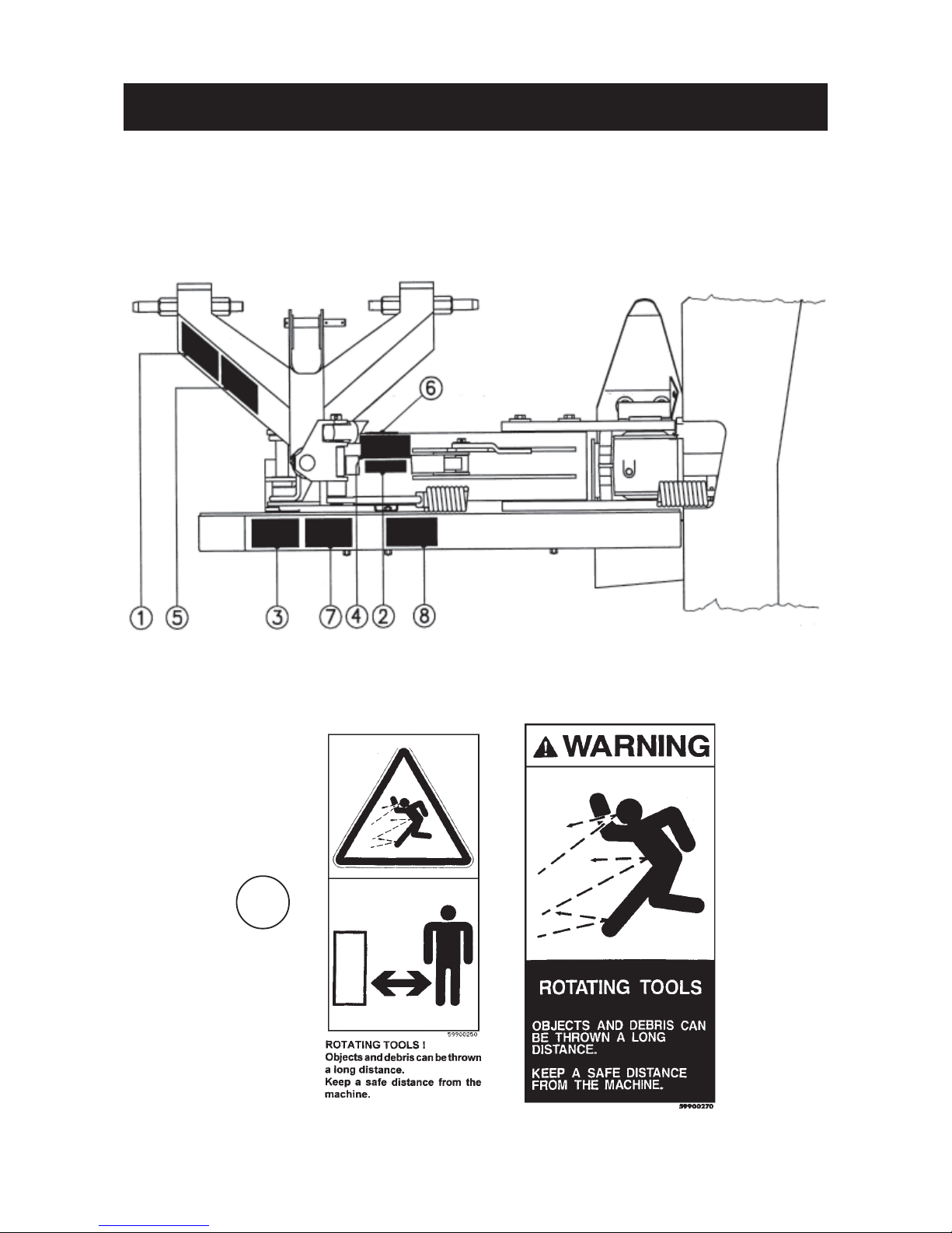
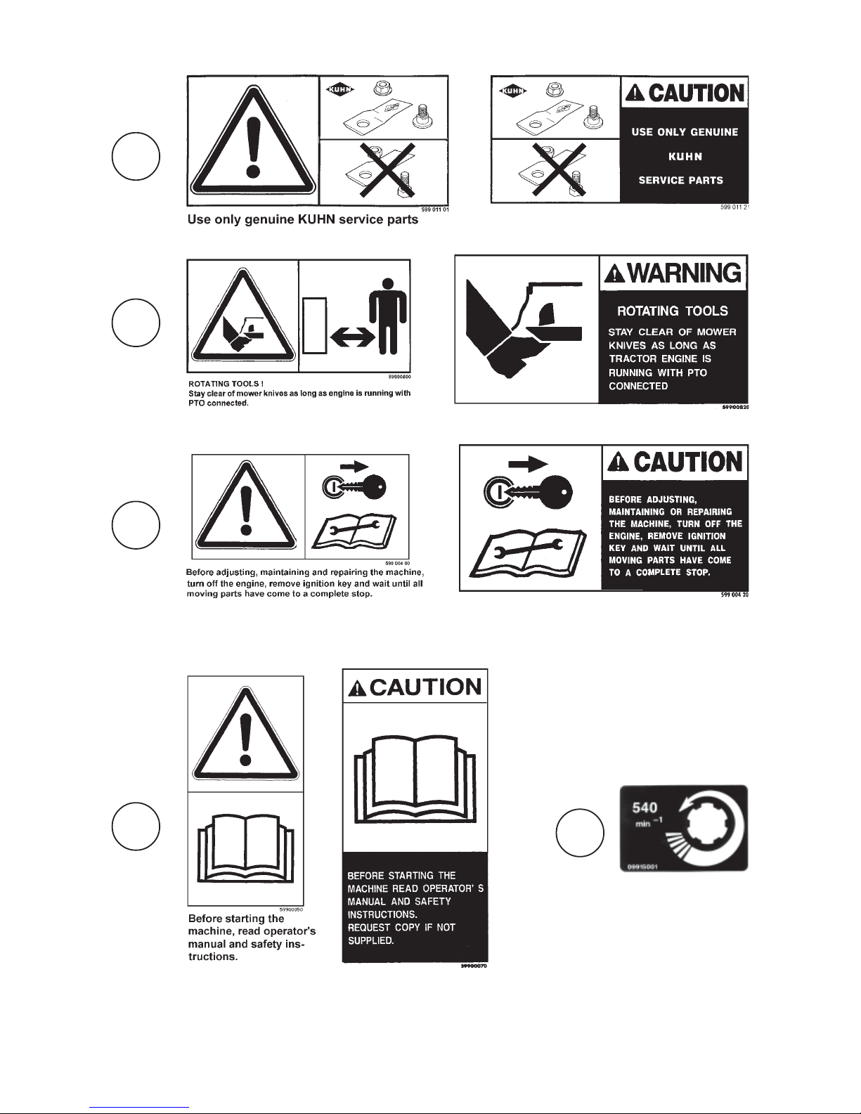
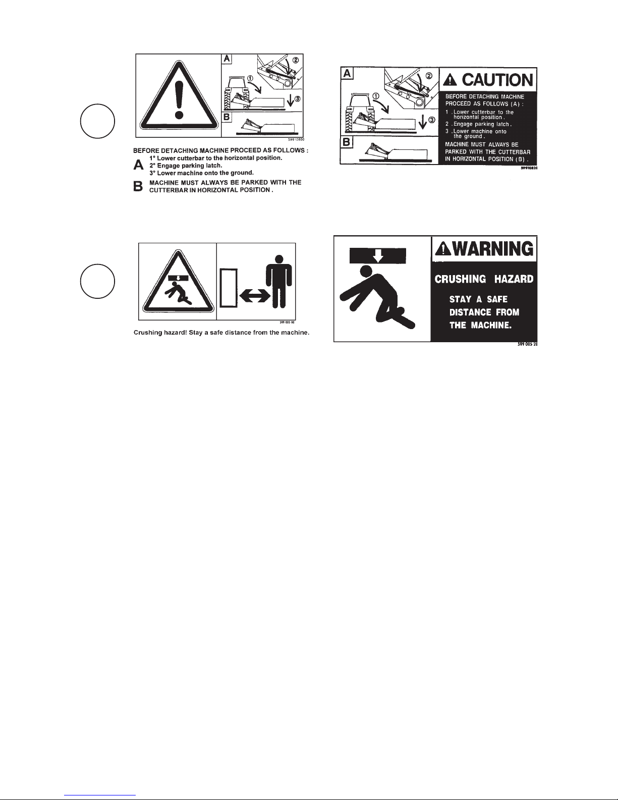
SAFETY DECALS
THE FOLLOWING SAFETY PICTORIALS HAVE BEEN PLACED ON YOUR MACHINE IN THE AREAS
INDICATED. THEY ARE INTENDED FOR YOUR PERSONAL SAFETY AND FOR THE SAFETY OF THE
PEOPLE WORKING WITH YOU. THE TEXT SHOWN ON THEM GIVES THEIR PRECISE MEANING.
KEEP THE PICTORIALS LEGIBLE. IF THEY ARE NOT, REPLACE THEM.
1
Page 11
- 9 -
2
3
4
5
6
Page 12
- 10 -
8
7
Page 13
- 11 -
Number of discs 6 7 8
Width of cut 2.40 m / 7' 10" 2.80 m / 9' 2" 3.10 m / 10' 2"
PTO power requirement 31 kW (42 hp) 37 kW (50 hp) 41 kW (56 hp)
P.TO. speed (rotational frequency) 540 rpm (min-1) 540 rpm (min-1) 540 rpm (min-1)
Disc speed (rotational frequency) 2986 rpm (min-1) 2986 rpm (min-1) 2986 rpm (min-1)
Width in transport position *0.17 m (7") wider than tractor width
Lift system **hydraulic **hydraulic **hydraulic
Weight (approx.) :
- GMD 600 GII / 700 GII / 800 GII 535 kg / 1177 lbs 567 kg / 1247 lbs 646 kg / 1421 lbs
- GMD 600 GII-HD/700 GII-HD/800 GII-HD 548 kg / 1206 lbs 582 kg / 1280 lbs 663 kg / 1459 lbs
Bevel gearbox oil capacity 0.45 l / 1 US pint
Oil quality : SAE 80 W EP (GL4) 0.75 Imp pint
Cutterbar oil capacity 2.00 l / 4.25 US pint 2.25 l / 4.75 US pint
Oil quality : SAE 80 W EP (GL4) 3.5 Imp pint 4 Imp pint
* Applicable if machine is attached in such a way that a 5 cm / 2" distance "A" is respected (see page 18).
** On tractor side a single acting outlet (preferably with free floating position) is required.
ASSEMBLY
To facilitate shipping of the disc mowers, certain parts or assemblies are partially disassembled to reduce bulk. To
assemble these parts proceed as follows :
TYPE GMD 600 GII GMD 700 GII GMD 800 GII
GMD 600 GII-HD GMD 700 GII-HD GMD 800 GII-HD
TECHNICAL SPECIFICATIONS
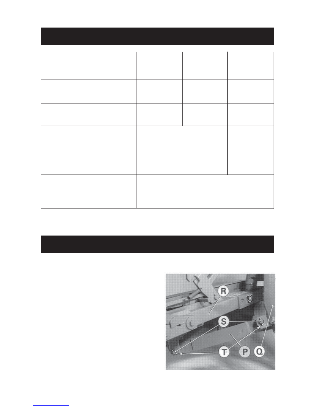
1. Fitting the break-away latch
Fit break-away latch (P) on headstock yoke (Q) and
main frame yoke (R) with 2 pins (S) and 4 roll pins (T)
(dia. 6 x 36) as shown in photo 1.
*0.21 m (8") wider
than tractor width
1
Page 14
- 12 -
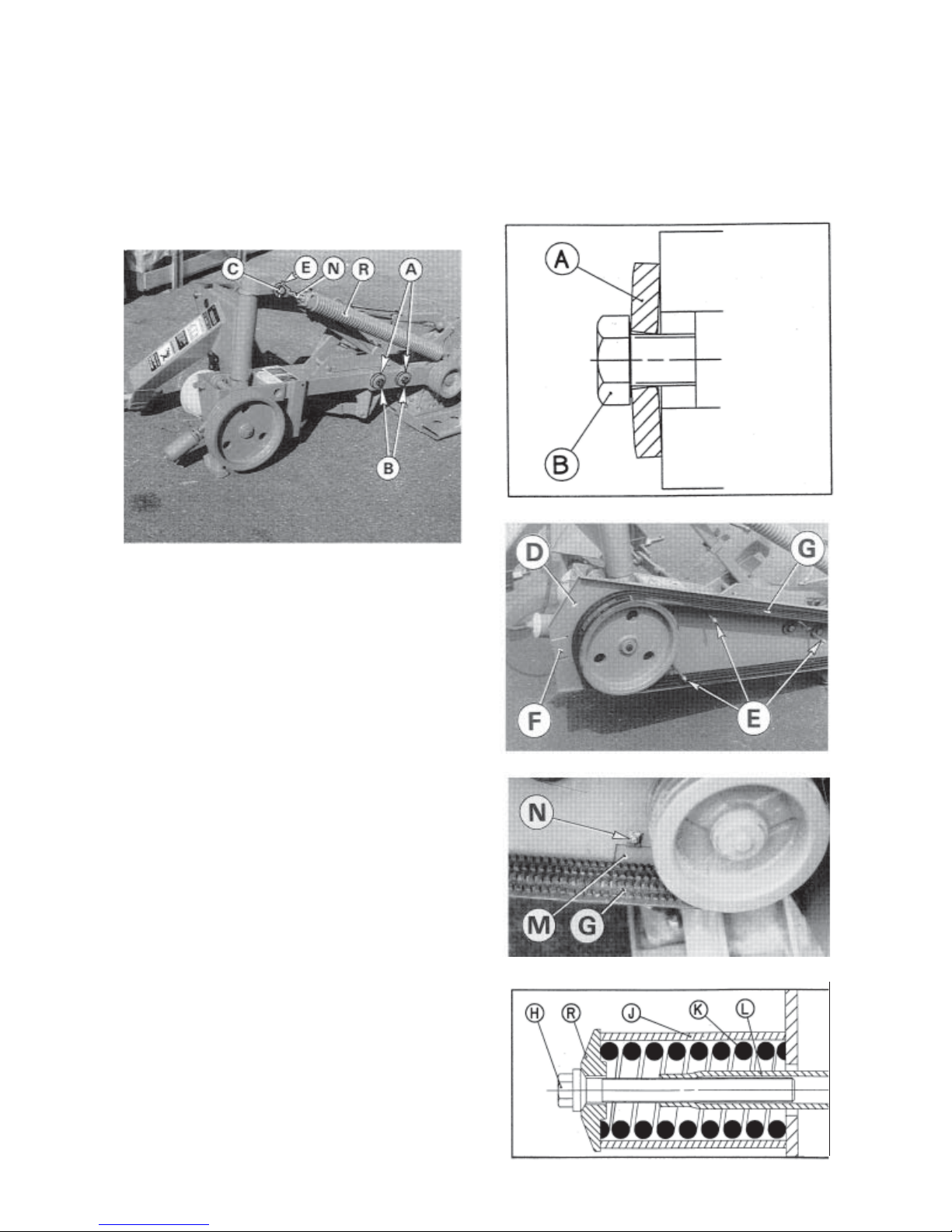
2. Mounting chassis to cutterbar
Make sure that the bore of nylon bushings is clean and well greased. Remove protective paint from the front cover
of bevel gearbox where bushings make contact.
Attach the frame to the cutterbar using 2 self locking screws (B) (M 16 x 50) and 2 washers (A) (diameter 16,5 x
60) as shown in photo 2 and fig.2. Torque : 30 daNm / 220 ft.lbs.
Install the compensating spring rod (N) to the pin (C) using roll pin (E) (diameter 8 x 50) (photo 2).
3. Assembly of belt shield and belts
- Install the inner belt shield (D) (photo 3) in place and
secure with the 3 spacer bolts (E) taped on the stop
chain. Torque to 5 daNm / 40 ft.lbs.
- Install closing plate (F) equipped with elastic nut as
shown in photo 3.
On GMD 800 GII / 800 GII-HD, mount the inner
closing plate (M) using an elastic nut and a selflocking screw (N) (M 8 x 12) (photo 3A).
- Install the V-belts (G) onto the pulleys (photos 3 and
3A).
- Place tensioning spring (K) inside spacer tube (J)
and install both parts over guide (L) (fig. 3).
- Slide special washer (R) onto bolt (H) and install this
bolt into guide (L) as shown in figure 3 and photo 3
A.
2
Fig. 2
3
3A
Fig. 3
Page 15
- 13 -
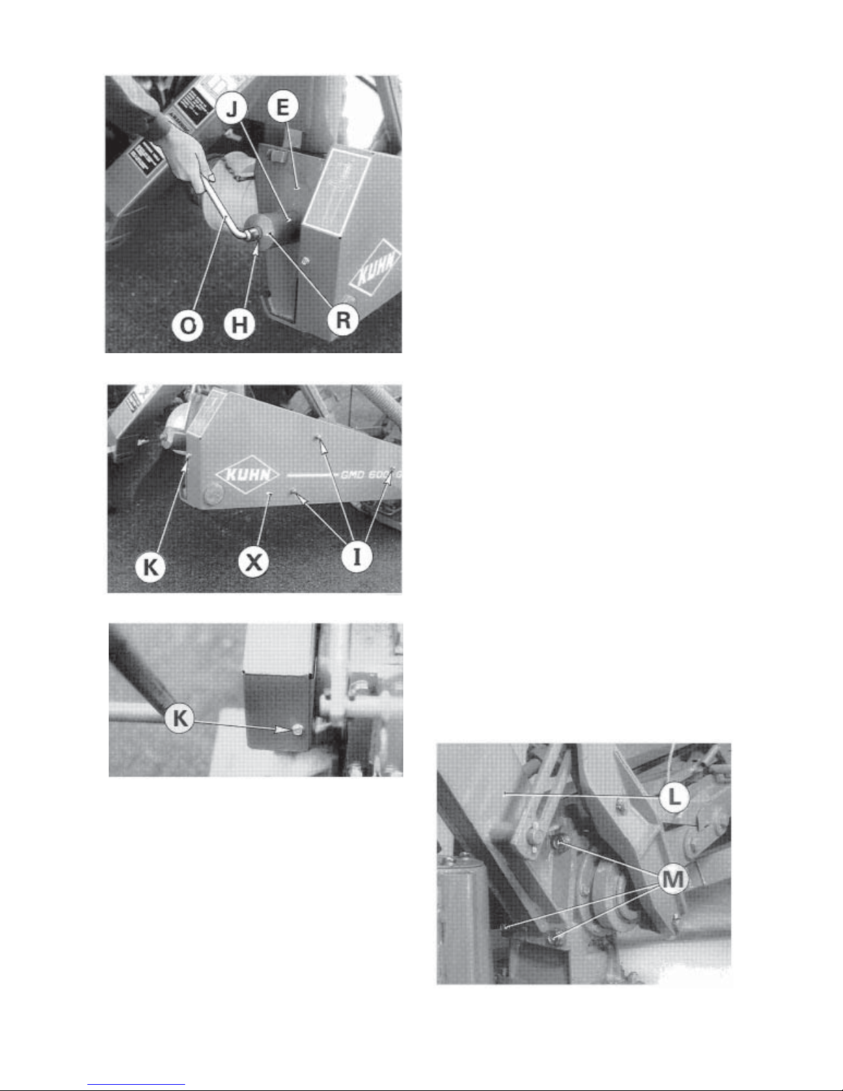
- Tension the V-belts (G) (photo 3) by tightening the
bolt (H) with the 18 mm box spanner (O), delivered
with the machine (photo 3 A).
- For the correct V-belt tension, tighten the bolt (H)
until the spacer tube (J) is in contact with the main
frame plate (E) and the washer (R), then tighten the
bolt with 2 additional complete turns.
Note : The 2 turns of the bolt necessary to obtain a
correct tension, only apply to new sets of belts
to compensate for the initial stretch new belts
are subject to during the first couple of hours of
use.
- Attach outer belt shield (X) with 3 washers and 3 cap
nuts (I) (photo 4). Torque : 5 daNm / 40 ft.lbs
- Assemble closing plate and outer belt shield with
one self-locking screw (K) (M 8 x 16) (photo 4).
On GMD 800 GII / 800 GII-HD, assemble the inner
closing plate and the outer belt shield with one selflocking screw (K) (M 8 x 12) (photo 4A).
4. Installing the frame pipe
- After cleaning attach frame pipe (L) (photo 5) to bevel
gearbox with 4 screws (M) (M 16 x 40). (Torque : 21
daNm / 155 ft.lbs).
3B
4
4A
5
Page 16

- 14 -
5° Installing pivoting lever, lift rod, connecting plate, cord and hydraulic hose
- Install pivoting lever (A) on pin (B) and secure with a
roll pin (dia 6 x 36) (photo 6)
- Install lift rod (N) (photo 6) on pin (0) and secure with
a roll pin (dia 6 x 36).
- Connect lift rod (N) and the cylinder rod connecting
plate ( C ) to the pivoting lever (A) with pin (Q) and 2
roll pins (dia 6 x 30) as shown in photo 6.
- Thread cord (D) through the eyelet (E), then attach
the metallic hook (X) to stop plate (G) and close the
hook's eyelet with a pair of pliers. This cord is factory
installed on transport latch (F) (photo 6 A).
- Thread cord (D') through eyelet (E') and through the
eyelet of transport latch (F) which already houses
cord (D). Then tie a knot (Y) to the loose end of cord
(D') (photo 6 A).
- Fix hose (Z) to cylinder using a hollow screw and a
copper washer on each side of the banjo joint (photo
6 A).
6° Compensating spring, inner shoe and inner swath board assembly
- Connect compensating spring (P) (photo 7) to axle
(R) of frame pipe and secure with 2 roll pins (dia.
8 x 40).
This operation is carried out easily by attaching the
machine to a tractor and raising the cutterbar until
the spring mounting hole lines up with pin (R).
- Fit inner shoe (I) by means of 4 cup square bolts (J)
(M 10 x 25) and 4 self locking nuts (M 10) (photo 8).
If it becomes necessary to transport the
machine on a trailer after assembly, the
compensating spring should not be
connected at this stage, thus allowing
the frame to rest securely on its left skid.
6
6A
78
Page 17

- 15 -
- Fix the inner deflector shield (S) (photo 8 A) using 3
cup square bolts (T) (M 10 x 20), 3 plain washers
(diameter 11 x 24 x 2) and 3 self locking nuts (M 10).
To assemble the shield (S) easily, install all of the
bolts (T) into place before tightening them.
The angular position of the swath wheel compared to the cutterbar can be adapted to working conditions
enabling a regular flow of the cut crop towards the rear.
Position the swath wheel so that maximum angle (A') (fig. 9 A) is obtained. In difficult working
conditions (long, dense, bent over crops) position it towards minimum angle (A) (fig. 9 A).
7. Installing outer disc with cone and outer swath wheel
- Attach the outer disc with cone using 4 hexagon
screws (M 12 x 20), 4 spring washers (conical centre
part towards the top) and, if necessary, a shim plate
(code 568 071 00) (see page 29, fig. 2), so that its
largest diameter is positioned at a right angle in
relation to the adjacent disc (see pictorial opposite).
Tighten to 12 daNm (90 ft.lbs).
- Attach swath wheel assembly (U) to outer skid shoe
(photo 9) with 2 cup square bolts (V) (M 12 x 35), 2
conical washers (dia. 13 mm) and 2 self-locking nuts
(M 12).
Torque : 8.5 daNm/65 ft.lbs
Before tightening screws (V), make sure that swath
wheel does not come into contact with cone cover or
knives.
Keep to a distance of X = 15 to 25 mm / 5/8" - 1".
8A
9A
9
Page 18

- 16 -
8. Safety guard and locking device assembly
- Attach the front safety bar (B) to its 3 hinges (C) with
the 5 cup square bolts (P) (M 10 x 25), 5 self-locking
nuts (O) (M 10) and 5 flat washers (Q) (Ø 11 x 24
x 2) (fig. 10).
- Then attach the pre-assembled front safety bar (B)
at (N) with 3 hexagonal screws (M 12 x 75) and selflocking nuts (M 12) (photo 11). Do not tighten these
3 screws completely, so that the front safety bar can
still pivot.
- Next attach rear safety bar (A) with 5 round head
bolts (P) (M 10 x 25) and 5 self-locking nuts (O)
(M 10) (fig. 10 and photo 11). Fit end-plug (Z) on
rear safety bar (A) (photo 11).
10
11
12
12A
Page 19

- 17 -
1. Minimum tractor power used should be 31 kW
(42 PTO hp) for the GMD 600 GII / 600 GII-HD, 37
kW (50 PTO hp) for the GMD 700 GII / 700 GII-HD
and 42 kW (57 PTO hp) for the GMD 800 GII / 800
GII-HD. If tractor power is not sufficient, quality of
work will not be satisfactory.
2. GMD 600 GII / 600 GII-HD, GMD 700 GII / 700 GII-
HD and GMD 800 GII / 800 GII-HD disc mowers can
be adapted to all tractors having a PTO speed
(rotational frequency) of 540 rpm (min-1) and
equipped with a normalized Cat. 2 three point hitch.
3. GMD 600 GII / 600 GII-HD, GMD 700 GII / 700 GII-
HD and GMD 800 GII / 800 GII-HD are equipped with
adjustable lower hitch pins allowing the machine to
be offset 50 mm (2") to the left and 50 mm (2") to the
right.
4. To adjust lower hitch pins (A) (photo 13), loosen the
4 hexagonal screws (H) of collar flanges (V) on each
side. Reposition lower hitch pins respecting dimension 825 mm (2’8") (page 18) and retighten screws
(H). Torque : 12 daNm/88 ft.lbs.
GENERAL INFORMATION
- Install cover (D) as shown in photo 12. Buckle straps around the pipe frame at E. Buckle straps (F) around front
and rear safety bar. All these straps are attached to the underneath of the safety cover.
- Punch 3 holes in the safety cover at (G) and use 3 cup square bolts (R) (M 10 x 35) with self-locking nuts (0) (M
10) (fig 9) and plain washers (Q) (dia. 11 x 24 x 2) to attach the following components on the outside arms of the
safety bars : safety guard locking device (S) ; safety cover (D) ; stop rod (J) (see fig. 10 and also refer to photos
11, 12 and 12 A).
- Fix the rubber stopper (W) onto the canvas frame using a nut (M8) (photo 12).
Note : Make sure that the pivot axis of the safety guard locking device (S) is lined up with the pivot axis
(N) of the front safety bar before tightening self-locking nuts (O).
CAUTION : ALWAYS OPERATE MOWER WITH SAFETY COVER IN PLACE AND THE
FRONT END OF THE COVER LOWERED. NEVER LEAN AGAINST OR STAND ON
SAFETY COVER.
The 18mm box spanner (T) delivered with the machine
has to be stored in holder (U) (photo 14).
This box spanner is used to make the following
operations :
- Unlocking the safety guard
- Tensioning the belts
- Tensioning the compensating spring
- Replacing knives
- Dismounting discs.
- Check the torque of the screws (H) after the first
ten hours of work following the modification of
the hitch pins’ position.
13
14
Page 20

- 18 -
ADAPTING TO TRACTOR
Attachment of lower links and
positionning of hitch pins :
Follow fig. 1 for category 2 tractors with narrow wheel
track.
Follow fig. 2 for category 2 tractors with standard
wheel track.
Follow fig. 3 for category 2 tractors with wide wheel
track.
NOTE : -Use the above approximate dimensions from
centre of tractor to outside of wheel to
determine if the tractor wheel track is narrow,
standard or wide.
- Always attach machine in such a way
that distance (A) is approximately 50
mm (2").
Follow fig. 4 for Cat. 2 tractors with very wide
wheel track. In this case a lengthened left hitch
pin for up to 200 mm (8") offset is required (see
optional accessories on page 38).
CAT 2
FIG. 4
CAT 2
FIG. 3
CAT 2
FIG. 2
CAT 2
FIG. 1
Page 21

- 19 -
1. Check that the 2 tractor 3-point lift rods (C) are
adjusted to an identical length.
2. Attach the lower links to the hitch pins and secure
with linchpins (A) (photo 16).
3. Attach the top link (P) using pin (D). Two positions
are available on the pin, depending on the diameter
of the ball joint, to secure the link to the mower.
4. Connect the hydraulic hose (X) to a single acting
outlet.
Note : A hitch pin (T) enabling direct attachment by
means of a quick hitch (N) is supplied with
GMD 800 GII machines intented for North
America (photo 16 A). Mount the pin (T) on the
3-point frame using 2 roll pins (H) (diameter 10
x 45), as shown on photo 16 A.
A quick hitch mounting bracket enabling a
quick hitch to be attached to GMD 600 GII /
700 GII models is available as an optional
equipment (see page 39).
5. Lift the machine off the ground using the hydraulic
3-point lift, fold the parking latch (L) upwards (see
arrow) until it engages in the spring (E) (photo 17).
When working or transporting the disc mower, the
parking latch (L) must be locked, as shown on photo
17 A.
17
17A
Page 22

- 20 -
Adjustment of chassis height from the
ground
1. For tractors equipped with hydraulic position
control function :
- On a level surface lower the 3-point lift until the stop
plate (G) engages in its housing and clears the rear
wall by a small gap such as "X" = 3 mm / 0.1" as
shown in photo 18.
- After having adjusted the chassis’ height, move the
stop against the 3-point lift control lever so that the
3-point lift lowers itself at the same depth each time
(photo 19).
2. For tractors not equipped with hydraulic posi-
tion control function the stop-chain delivered with
the machine must be used.
- Connect stop-chain (D) with its hook (G) supplied in
the hardware kit of the machine to one of the free
holes at the tractor’s top link attachment clevis.
- Lower the machine into working position until the
stop plate (G) engages in its housing (photo 18) and
the stop chain (D) is tight (photo 20).The stop plate
should then clear the rear housing wall by a small
gap such as "X" = 3 mm / 0.1" (photo 18). The 3point frame height is correct when :
- The cutterbar is resting on the ground.
- The stop plate is engaged in its housing (clearance "X" being approximately 3 mm / 0.1")
- Stop-chain (D) is tight.
- To keep this adjustment permanently, close hook
eyelet (S) with roll pin (dia. 5 x 45 mm).
20
19
18
Page 23

- 21 -
P.T.O. SHAFT
Connect the PTO shaft to the 540 rpm (min-1) tractor drive (with the free wheel fitted on the machine side).
Make sure PTO length is correct :
1°When the PTO is in its maximum extended position, a minimum tube overlap of 250 mm (10") must be maintained.
2°When the PTO is in its maximum overlap position (retracted), tubes should not butt against the yokes. As a safety
measure a clearance of at least 10 mm (2/5") must be maintained (fig. 21). If this is not the case, shorten the
two transmission tubes and the two guard tubes by the same length (fig. 22 and 23). Bevel and clean the tubes
(fig. 24) and grease the inside of the outer tube (fig. 25).
3°Never operate the PTO at too great an angle (X = +/- 30° maximum) (fig. A).
These recommendations and adjustments must be respected to avoid damage or premature wear of
the PTO.
Never connect the PTO to the 750 or 1000 rpm (min-1) tractor drive.
A
25
24
21
22
23
B
To avoid accidents which could be
serious, make sure that the guards
are always correctly in place and
secured with the safety chains. On
machine side attach the safety chain
to the main frame (photo B). Worn or
damaged guards should be replaced
immediately.
Page 24

- 22 -
TRANSPORT
To transport the machine on public highways or from
one field to another, proceed as follows :
1) Disengage the PTO drive and wait for all
movement to stop.
2) Release lock by applying pressure with the box
spanner (A - arrow 1) supplied with the machine and
fold the front safety bar upwards (arrow 2) (photo
26) till it is automatically locked in transport position.
3 ) Pull on the rope (F) to disengage the lifting stopper
(G) (photo 27).
4 ) Raise the machine with the tractor 3 point linkage.
5 ) Slowly raise the cutterbar vertically using the hy-
draulic cylinder. Slacken the tension on the rope
(F) as the cutterbar is being pivoted in the
vertical position. It will automatically be locked in
full transport position (photo 28) by the latch (C)
(photo 27).
WARNING : BEFORE PUTTING THE
MACHINE IN WORK OR TRANSPORT
POSITION, ENSURE ALL PERSONS
ARE WELL CLEAR OF THE
CUTTERBAR PIVOTING AREA.
BEFORE TRANSPORTING THE
MACHINE ON THE PUBLIC HIGHWAY, THE OPERATOR SHOULD
MAKE SURE THAT THE MACHINE
CONFORMS TO THE HIGHWAY
CODE.
The cord (F) (photo 27) must be pulled each time when raising the cutterbar in the full vertical
position.Slacken the tension on the rope as the cutterbar is being pivoted in the vertical
position.
THE OVERALL TRANSPORT HEIGHT MEASURED FROM THE GROUND MUST NOT EXCEED 4
METRES/13' (MAXIMUM HEIGHT AUTHORISED BY THE HIGHWAY CODE).
28
27
26
Page 25

- 23 -
WORKING POSITION
WARNING : BEFORE PUTTING THE MACHINE IN WORK OR TRANSPORT POSITION, ENSURE
ALL PERSONS ARE WELL CLEAR OF THE CUTTERBAR PIVOTING AREA.
With the machine in transport position, proceed as
follows :
1) Pressurise the hydraulic cylinder to relieve the
transport lock (C) (photo 29).
2 ) Pull cord (F) to free latch (C) (photo 29).
3) Lower the cutterbar down to the horizontal position
by releasing hydraulic pressure.Use the valve detent
to maintain the valve in position "release", or shift
the valve into the free floating position to allow the
cutterbar to travel up and down with respect to the
ground countours.
4) Release lock by applying pressure with the hand
palm (arrow 1) and fold front safety bar (V) downwards
(arrow 2) (photo 30) till it is automatically locked in
working position.Never operate machine with
the safety curtain folded back for transport.
5) Check adjustment of chassis height from the ground.
The stop plate (G) should be engaged in its housing
and clear the rear housing wall by a small gap such
as "X" = 3 mm / 0.1" (photo 30A).
29
30
30A
Page 26

- 24 -
OPERATING THE MOWER
ENSURE THAT THE SAFETY
CURTAIN IS COMPLETELY IN
PLACE AROUND THE CUTTERBAR.
- Safety curtain will avoid projection of most foreign
objects.
- Always allow a few minutes for oil to spread in the
cutterbar before engaging PTO when changing
cutterbar from transport to operating position. Before
cutting, engage tractor PTO and slowly increase
speed (rotational frequency) up to 540 rpm (min-1).
- Forward speed must be adapted to working condi-
tions.
- During work the tractor valve should always be
in the detented free floating position to ensure
mower will follow variations in ground contour.
- When manoeuvring on headlands, the cutterbar
is raised and lowered using the mower hydraulic cylinder (photo 32). The lift linkage is conceived
to clear the main frame from the ground at the same
time as the cutterbar lifts itself. To do this, activate
the hydraulic cylinder until the cylinder parking latch
(S) comes up against the stop (photo 31).
- The GMD 600 GII / 600 GII-HD, GMD 700 GII / 700
GII-HD and GMD 800 GII / 800 GII-HD allows the
mowing of banks of up to 35° below horizontal.
NEVER MOW IN STONY OR ROCKY GROUNDS.
NEVER OPERATE THE MOWER WITHOUT THE PLASTIC COVER IN PLACE. DO NOT
LEAN AGAINST OR STAND ON THE GUARD COVER.
32
31
S
Page 27

- 25 -
CUTTING HEIGHT
Maximum cutting height (50 mm / 2") (fig. 1) is
achieved when the discs are parallel to the ground.
Adjustment of cutting height is achieved by altering the
cutterbar tilt angle. This is effected by varying top link
length (H) (photo B) until desired cutting height is
achieved. To minimize blade and disc wear, improve
grass regrowth and get maximum nutritive value from
the crop, minimum cutting height should never be
adjusted less then 30 mm / 1 1/4" (fig. 2).
OUTER SWATH WHEEL
The angular position of the swath wheel
compared to the cutterbar can be adapted
to working conditions enabling a regular
flow of the cut crop towards the rear.
Position the swath wheel so that maxi-
mum angle (A') (fig. A) is obtained. In
difficult working conditions (long, dense,
bent over crops) position it towards mini-
mum angle (A) (fig. A).
ADJUSTMENTS
An adjustable cutting height from 35 to 90 mm can be obtained by replacing the end skids by 2 raised skid shoes
(see optional accessories).
B
A
MAXIMUM CUTTING
HEIGHT
MINIMUM CUTTING HEIGHT
Fig.1 Fig.2
Page 28

- 26 -
SAFETY BREAK-AWAY
The factory setting of the latch is adapted to most working conditions.
The stack of spring washers (A) should be compressed to Y = 95 mm (3 3/4") (fig. 3 and photo 34). Observe spring-
washer arrangement in fig. 3 carefully.
If after resetting, the cutterbar continues to break away, the pressure of spring assembly (A) (photo 34) can be
increased, but in all cases stacking must not be less than 91 mm (3 2/3"), as otherwise safety disengagement cannot
function.
NOTE : Before using the mower, the break-away linkage must be checked for good operation making sure all
components slide correctly and are well greased. Check for any cutterbar damage if an obstruction is
encountered.
A breakaway latch allows the cutterbar to swing back
if an obstruction is hit (photo 33).
IF THE LATCH RELEASES, STOP THE TRACTOR
IMMEDIATELY AND DISENGAGE THE PTO.
To reset the cutterbar, back the mower until the
cutterbar is in its normal position.
33
34
3
Page 29

- 27 -
PARKING THE MACHINE
FOR YOUR SAFETY : ALWAYS PARK THE MACHINE WITH THE CUTTERBAR IN THE
HORIZONTAL POSITION.
Do not allow the cutterbar to lower
below horizontal when setting it in
parking position (photo A).
- Using the mower hydraulic cylinder, lower the cutterbar into the horizontal position.
- Release the parking latch (L) (see arrow) (photo 35) and engage it behind the bevel gearbox mounting
plate (R) (photo 35 A). Make sure no foreign material is located on top of the bevel gearbox.
- Release the 3-point lift valve to lower the machine to the ground.
- Remove the top hitch pin from the headstock and disconnect the hydraulic hose.
- Then disconnect the lower tractor draught arms and the PTO transmission shaft.
- Place the PTO shaft (T) into the support (U) as shown in photo 36.
35
35A
36
A
Page 30

- 28 -
Discs, knives and securing elements are manufactured from high quality steel and have been subjected
to a heat-treatment to assure a high resistance to
wear.
Worn or damaged items must immediately be
replaced with genuine KUHN parts as otherwise
warranty will be withdrawn.
ADJUSTMENTS AND MAINTENANCE
CAUTION : BEFORE CARRYING OUT SERVICE OR ADJUSTMENTS TO THIS MACHINE,
TURN OFF THE TRACTOR ENGINE, REMOVE IGNITION KEY AND DISCONNECT THE PTO
SHAFT.
Adjust machine to clear obstructions and debris. Foreign objects and other debris can be
deflected toward the operator and bystanders.
1. INSPECTION OF KNIVES AND SECURING ELEMENTS
A) KNIVES : should be inspected systematically
each time before the machine is operated.
Cutting quality as well as safe operation depend on the
regular inspection and care given to the knives. Knives
should be replaced in the following cases :
a) Damaged knives
Very rough conditions can cause knives to crack
and become deformed leading to :
- increased risk of accidents ;
- deterioration of cutting quality ;
- risk of damage to the cutterbar.
b) Worn knives
Length (A) of a knife should be greater than 65 mm.
The width (B) of a knife, measured at a distance
of 10 mm away from the edge of the disc should
be greater than 34 mm.
The hole (L) for the securing bolt must not become
oval by more than 20 mm for an 18 mm hole.
Page 31

- 29 -
B) SECURING ELEMENTS : To be inspected
regularly !
(particularly the tightening torque of the nut:
12 daNm / 90 ft.lbs).
- Inspect immediately after hitting an obstruction.
- Inspect when replacing knives.
- Check at the beginning of each season.
a) The securing bolt must be replaced :
- When a visible deformation is found.
- When the locking compound on the threads has
worn away or if the locking compound has become
inoperational due to inclusion of water, oil or dirt.
- When wear on the head reaches the contact area of
the knife.
- When the diameter (D) of the bolt shoulder is less
than 15 mm (5/8 ").
b) The nuts must be replaced :
- When the contact washer has lost its elasticity or
when it becomes loose from the nut.
- When wear on the nut reaches a = 5 mm.
FOR THE CORRECT OPERATION OF YOUR
MACHINE,
ALWAYS USE GENUINE KUHN SPARE PARTS.
Page 32

- 30 -
2. KNIFE REPLACEMENT
To replace knives, first clean the area around nut (A)
(photo 37) and remove nut with the box spanner (T)
supplied with the machine. To facilitate the removal of
the nut, we recommend to place a block of wood (Z)
between 2 discs to stop them from rotating (photo 37).
Remove the bolt (W) through the hole located at the
front of the disc guard (photo 38).
Ensure securing elements are in good condition and fit
knives so that the arrow on their upper face is pointing
in the direction of rotation of the disc (fig. 39) it is fitted
to.
Torque locknut to 12 daNm / 90 ft.lbs.
GMD 600 GII
GMD 600 GII - HD
GMD 700 GII
GMD 700 GII - HD
GMD 800 GII
GMD 800 GII - HD
Fig.39
37
38
Page 33

- 31 -
IMPORTANT : ALWAYS REPLACE SECURING ELEMENTS (LOCK-NUTS AND BOLTS)
WHEN THEY HAVE BEEN REMOVED 5 TIMES.
CAUTION : ALWAYS REPLACE DAMAGED KNIVES, NEVER STRAIGHTEN A BENT
KNIFE.
NEVER REPLACE ONE KNIFE ONLY PER DISC, ALWAYS REPLACE BOTH OF THEM TO
AVOID CREATING AN OUT-OF-BALANCE FORCE.
3. DISCS REPLACEMENT
To replace a disc, place a block of wood (Z) between
two discs to stop them from rotating. Unscrew the 4
nipple-screws (B) with the box spanner (T) supplied
with the machine and take the 4 conical spring washers
(C) off (photo 41 and fig. 42).
Two of these diametrically opposite bolts are also used
to secure the conical covers on top of the discs.
When remounting must the discs have their largest
diameters positioned at right angles to each other. This
positioning must be scrupulously respected so as to
avoid interference between the knives.
Take extra care when fitting the conical spring washers
(C) (fig. 42), which must be positioned with the conical
centre at the top.
Tighten bolts to a torque of 12 daNm (90 ft.lbs).
THE GMD 600 GII / 700 GII / 800 GII
DISCS SUPPLIED THROUGH OUR
SPARE PARTS DEPARTMENT
COME WITH A 1 MM SPACER (PART
no. 568 071 00) (fig. 40) ATTACHED
TO THEM. WHEN INSTALLING A
NEW DISC CHECK IF THE GAP
BETWEEN THE BLADES OR THEIR
MOUNTING BOLTS AND THE
CUTTERBAR PROTECTION
SHIELDS IS AT LEAST 1 MM. IF
THIS IS NOT THE CASE FIT THE 1
MM SPACER BETWEEN THE DISC
AND ITS MOUNTING HUB FOR
INCREA-SED CLEARANCE (fig. 40).
THIS SPACER IS NOT REQUIRED
ON DISCS FOR GMD 600 GII-HD /
700 GII-HD / 800 GII-HD.
Dull knives require more horse power to cut the crop
and will leave an uneven stubble.
Worn knives should either be turned over on the same
disc to use the other cutting edge, or replaced. When
turning or replacing the knifes, make sure there is a 1
mm minimum gap between the knives or their mounting bolts and the cutterbar wear plates. If otherwise,
insert one (maximum two) distance spacer(s) (code
568 071 00) between the discs and the disc bearing
stations (only for GMD 600 GII / 700 GII / 800 GII) (fig.
40).
42
41
40
Page 34

- 32 -
4. BELTS
Belts must be properly tensioned at all times to avoid
excessive flopping and slipping. Loose belts will also
cause poor cutting and premature wear.
Tension the belts by tightening the bolt (H) with the
18 mm box spanner (O) delivered with the machine
(photo 45).
For the correct V - belt tension, tighten the bolt until the
spacer tube (J) is in contact with the main frame plate
(E) and the washer (R).
During the initial assembly and when fitting new Vbelts, it is necessary to give 2 additional complete
turns of the bolt (H) in order to obtain the correct
tension.
Regularly check the tension of the V-belts, particularly
during the first hours of use.
Note : Belts must never be changed individually. If one of them becomes damaged, the whole set must be replaced
: - code no 831 017 91 for GMD 600 GII / 600 GII-HD - 700 GII / 700 GII-HD
- code no 831 017 92 for GMD 800 GII / 800 GII-HD.
REGULARLY CHECK ALL NUTS AND BOLTS FOR CORRECT TIGHTNESS,
PARTICULARLY THOSE SECURING THE DISCS AND KNIVES.
Make sure cone lids (J) are properly secured in place (photos 43 and 44). Replace immediately a loosen or damaged
cone lid.
45
43
44
Page 35

- 33 -
5. ADJUSTMENT OF COMPENSATING
SPRING TENSION
The tension of the compensating spring rod is factory
set so that dimension (X) (photo 46) is 120 mm
(4 2/3") for the GMD 600 GII / 600 GII-HD, and 90
mm (3 1/2") for the GMD 700 GII / 700 GII-HD / 800 GII
/ 800 GII-HD.
When the working conditions are difficult, the setting
can be modified. To decrease machine ground pressure, reduce dimension (X) by proceeding as follows
:
- Raise the cutterbar until the spring (P) is slack.
- Using the box spanner supplied with the machine,
untighten lock-nut (H) and rotate suspension spring
(P).
- After setting, re-tighten the lock nut (H).
46
Page 36

- 34 -
It is forbidden to discard oil, grease or filters of any type. These must be given to specialised
waste disposal organisations to protect the environment.
IMPORTANT
Imperatively change oil in : - cutterbar bevel gearbox
- cutterbar
after the first 10 hours of use [SAE 80 W EP (GL4)].
Thereafter, oil must be changed every 200 hours of work and at least once per year.
NOTE : Before draining oil, operate the cutterbar for a few minutes so that oil warms up.
LUBRICATION
GMD 600 GII GMD 700 GII GMD 800 GII
GMD 600 GII - HD GMD 700 GII - HD GMD 800 GII - HD
Quantity of oil in the bevel 0.45 litre / 1 US pint 0.45 litre / 1 US pint 0.45 litre / 1 US pint
gearbox [SAE 80 W EP (GL4)] 0.75 Imp. pint 0.75 Imp. pint 0.75 Imp. pint
Quantity of oil in the cutterbar 2 litres/4.25 US pints
2 litres/4.25 US pints 2.25 litres/4.75 US pints
[SAE 80 W EP (GL4)] 3.5 Imp.pints 3.5 Imp.pints 4 Imp.pints
1. BEVEL GEARBOX
Plug (C) (photo 47) serves as a check plug when the
bar is horizontal. Remove plug (C). When oil level is
at its maximum, it will just begin to flow out of the hole.
Check oil level once a day. Add oil through filler plug (B)
(photo 47) if required.
The pressure relief valve (A) (photo 47) must be
checked and cleaned regularly. The ball detent must
be free to relieve pressure.
The maximum oil capacity of this gearbox is as shown
in the table below and it is important not to exceed
this quantity.
Plug (C) is also used as a drain plug when the
cutterbar is in the vertical transport position.
47
Page 37

- 35 -
2. CUTTERBAR
Note : Make sure the cutterbar is in the vertical position
when checking, adding or changing oil.
The oil level is at its maximum when oil flows out of the
filler plug hole.
Check oil level once a day. Add SAE 80 W EP (GL4)
oil to the cutterbar at filler plug (D) (photo 48).
To drain oil, remove magnetic drain plug (E) (photo 48)
located underneath the cutterbar below the bevel
gearbox.
Clean all metal particles off the magnetic drain plug
before refitting.
NOTE : Provided above intructions are strictly observed,
there is no cause for alarm if it is found that the
transmission case is very hot to touch, provided that
the discs turn freely by hand. .
Attention : Before carrying out this check, turn off
the tractor engine, remove ignition key and disconnect the PTO shaft.
3. PTO SHAFT
Lubricate the PTO shaft at the hourly intervals indicated
in figure 49 with SHELL Multi-Purpose grease NlGI
grade 2.
The recommended grease and oil change periods are based on normal field and work
conditions.
Severe or unusual conditions may require more frequent lubrication or oil changes.
RESPECT SPECIFIED OIL QUANTITIES AND GRADES : SAE 80 W EP (GL4) OIL ONLY.
4. GREASE FITTINGS
Clean fittings before applying grease. Oil all pivot and linkage points every fifty hours.
Grease breakaway sliding components as required.
49
48
[In certain countries SAE 80 W EP (GL4) oil may not be available. In this case a GL4 or GL5 grade
SAE 80 W 90 oil may be used as a replacement. Never use a straight EP 90 oil].
Page 38

- 36 -
OPTIONAL EQUIPMENT
1. Hydraulic adaptators (photo 50)
For fitting to different types of hydraulic connectors,
three adaptators are available :
M16 x 1.5 / 1/2 GAZ - CON 22 (823 012 05)
M16 x 1.5 / 1/2 NPT - 24 (823 012 06)
M16 x 1.5 / 3/4 UNF - JIC (823 019 02)
2. High cone
(kit No. 104 6170 for GMD 700 GII)
(kit No. 104 6180 for GMD 700 GII - HD)
To reduce swath width to 1.70 m - 1.80 m (approx. 5' 7" - 5' 11") on the GMD 700 GII / 700 GII - HD, the second disc
can be replaced by a cone (C) (photo 51).
Tighten fixation bolts to 12 daNm / 88 ft.lbs.
3. Inside swath wheel
(kit No. 104 6100 for GMD 700 GII)
(kit No. 104 6190 for GMD 700 GII - HD)
On the GMD 700 GII and GMD 700 GII - HD an inside
swath wheel can be installed in conjunction with the
second high cone (C) (n° 104 6170 and n° 104 6180).
This set enables reducing the swath width to 1,55 m
(approx. 5').
The swath wheel (I) is attached to the frame pipe with
2 screws (E) (M 12 x 20) and 2 conical spring washers,
as shown in photo 51.
Torque of screws : 12 daNm / 88 ft.lbs.
51
Page 39

- 37 -
4. Inside swath wheel
(kit No. 103 6130 for GMD 600 GII)
To reduce swath width to 1,50 m (approx. 5'), an inside
swath wheel can be mounted on the GMD 600 GII.
The swath wheel (E) is attached to the frame pipe with
2 screws (A) (M 12 x 20) and 2 conical spring washers
as shown in photo 52.
Torque of screws : 12 daNm / 88 ft.lbs.
5. lnner swath board
(kit no. 103 6200 for GMD 600 GII)
(kit no. 104 6150 for GMD 700 GII)
The inner swath board set enables reducing the swath width to 1.20 m on the GMD 600 GII and to 1.25 m on the
GMD 700 GII (approx. 4' on either models).
This set is to be used when combined with the first inner disc with cone and the inner swath wheel (n° 103 6130)
on GMD 600 GII.
On the GMD 700, it must be used in combination with the second high inner cone (n° 104 6130) and the inner swath
wheel (n° 104 6100).
53
52
Page 40

- 38 -
Before assembling the inner swath board, the mounting
bracket (B) must be welded on the cutterbar stiffener
(M) following the instructions on figures 53 and 54.
GMD 600 GII : X = 430 mm
GMD 700 GII : X = 720 mm.
Fit the inner swath board support plate (A) on the
mounting bracket (B) with 3 cup square bolts (V)
(M 12 x 30) and 3 self locking nuts (O) (M 12) (torque:
8 daNm / 60 ft.lbs) (figure 53).
Next fit the inner swath board (C) on the support (A) by
means of a cup square bolt (J) (M 12 x 80), a pressure
spring (R), a dished washer (S) and a self-locking nut
(T) (M 12) (figure 53). Do not overtighten the nut so that
the board (C) can oscillate around the fixing bolt (J).
To finish the job, fix the swathing stick (D) on the plate
(C) with 2 cup square bolts (E) (M 8 x 50) and (F) (M
8 x 30), a spacer (G) and 2 self-locking nuts (H) (M 8)
(figure 53).
6. Lengthened left hitch pin
(kit No. 568 207 00)
For offsetting the machine up to 200 mm (8") a
lengthened hitch pin (T) (photo 55) can be mounted
on the left arm of the 3-point frame (looking in the
direction of travel).
Installation : see page 17.
7. Raised skids (fig. 56)
(kit No. 103 6230)
A raised skid shoe kit comprising 2 raised skids is
available as an optional equipment. This kit serves 2
purposes :
- providing a cutting height adjustable between
35 mm and 90 mm (1.5" and 3.5"),
- operating on sticky grounds.
This 2 raised skids are installed instead of the 2
regular end skids.
56
54
55
Page 41

- 39 -
8. Signalling elements (photo 57)
(kit No. 102 6100)
Signalling elements can be ordered as an optional
extra. To install this kit proceed as follows :
- Attach tail lamp (N) to panel (A).
- Bolt panel (A) to support (S) with 3 hexagon screws
(E) (M 10 x 20), 3 plain washers (dia. 11 x 24 x 2) and
3 self-locking nuts (M 10).
- Attach guide (H) to the rear guard tube (T) with an U-
bolt and 2 self-locking nuts (L) (M 10).
- Plug electric cable (O) into the lamp terminal (N).
In transport position mount the panel (A) with its
support (S) in the guide (H) with lock (U) and plug
electric cable at the rear of the tractor.
Before putting the machine in
work position, dont forget to
unbolt the panel.
9. Quick hitch bracket (kit No. 103 6170
for the GMD 600 GII - 700 GII)
This kit is available as optional equipment for North
America.
Attach bracket (H) to 3-point frame (K) with 2 bolts (L)
and 2 self locking nuts (M 18) (photo 58).
GMD 800 GII machines are equipped with a quick hitch
compatible 3-point frame (see page 19).
57
58
10. 1000 rpm drive kit (for GMD 800 GII and GMD 800 GII – HD) (Kit no. 1066010)
To install the 1000 rpm drive kit on machines already in service, refer to instructions no. L6800530 supplied with
the equipment.
Page 42

- 40 -
Uneven stubble Dull or broken knives Replace knives
Knives not installed Make sure that the arrow on the knife
correctly upper face is pointing in the direction
of rotation of the disc (see page 30)
Low disc speed (rotational Check belts for correct tension
frequency) (see page 32)
Low PTO speed (rotational Increase engine speed (rotational fre-
frequency) quency) to run PTO at 540 rpm (min-1)
Too much tilt on cutterbar Reduce tilt (see page 25)
Stubble too long Incorrect angle on cutterbar Change cutterbar angle using
tractor top link (see page 25)
Insufficient cutterbar Adjust compensating spring tension
down pressure (see page 33)
Adjust main frame height (page 20)
Soil built up in front of Too much cutterbar Adjust compensating spring tension
cutterbar down pressure (see page 33)
Very wet conditions Adjust main frame height by
shortening chain as necessary
(see page 20)
Fit a set of raised skids (see page 38)
Cutterbar not floating The cylinder cannot travel Set the tractor spool valve in float
up and down at will position
Compensating spring not Adjust the compensating spring
well adjusted tension (page 33)
Wear or seizing of the bevel Check the condition of the bushes and
gearbox mounting bushes replace them if necessary
Machine breaking back Insufficient tension on Tighten breakaway spring
too easily breakaway spring washers washers (see page 26)
Excessive ground speed for Slow tractor ground speed
field conditions
PROBLEM CAUSE REMEDY
TROUBLE SHOOTING GUIDE
Page 43

- 41 -
STORING THE MOWER
II - AT THE BEGINNING OF THE SEASON
1. Retension the V-belts (see adjustments section). Make sure the guard is firmly secured in place.
2. Inspect all knives and the hardware used to hold them in place (see the corresponding section).
3. Check that all nuts and bolts are sufficiently tightened.
4. READ THIS OPERATORS MANUAL ONE MORE TIME.
I - AT THE END OF THE SEASON
1. Thoroughly clean the mower conditioner.
2. Drain oil from all gearcases and cutterbars and refill with the precribed quantity of the correct grade oil. Apply
grease to all fittings as described in the lubrication section.
3. Repaint the rusted parts of the machine and all areas were the paint has worn off.
4. Slacken the V-belts and check their condition.
5. Store the machine with the cutterbar in operating position in a dry place.
Page 44

- 42 -
GMD 600 GII GMD 700 GII GMD 800 GII
GMD 600 GII-HD GMD 700 GII-HD GMD800 GII-HD
Tractor only 76.0 dB (A) 76.0 dB (A) 76.0 dB (A)
Tractor + machine 80.3 dB (A) 80.6 db (A) 80.6 db (A)
SOUND LEVELS
Sound levels given out by : GMD 600 GII / GMD 700 GII / GMD 800 GII
GMD 600 GII-HD / 700 GII-HD / 800 GII-HD Multidisc Mowers
Sound levels have been measured in accordance with the measuring methods as defined in :
HM Agricultural Inspectorate
AGRICULTURAL MACHINERY NOISE
Legislation and guidance on methods of testing
(Annex to AIC 1896/117 REV)
February 1988
Health and Safety Executive
The method employed corresponds to the method No. 4 in this document. Unspecified testing
conditions comply with ISO 5131 standard.
Measuring equipment conforms to NF S 31-009 standard. The tractor used has a power of 92 kW.
A-weighted emission sound pressure level L (A) eq inside tractor cab (with closed windows) :
Page 45

LIMITED WARRANTY
KUHN S.A. of 4 Impasse des Fabriques, 67706 SAVERNE CEDEX, France (hereinafter called the
«Company») warrants, in accordance with the provisions below, to each original retail purchaser of
KUHN new equipment of its own manufacture, from an authorized KUHN dealer, that such equipment
is, at the time of delivery to such purchaser, free from defects in material and workmanship and that
such equipment will be warranted for a period of one year starting from the date the goods are delivered
to the end user and during this period up to a limit of 500 hours use, providing the machine is used and
serviced in accordance with the recommendations in the Operator’s Manual.
THESE CONDITIONS ARE SUBJECT TO THE FOLLOWING EXCEPTIONS :
1. Parts of machines which are not of our manufacture i.e. tyres, belts, P.T.O. shafts, clutches etc., are not
covered by this Limited Warranty but are subject to the warranty of the original manufacturer. Any claim
falling into this category will be taken up with the manufacturer concerned.
2. Warranty claims applying to these types of parts must be handled in the same way as if they were parts
manufactured by KUHN. However, compensation will be paid in accordance with the warranty agreement of the manufacturer concerned in as much as the latter justifies such a claim.
3. This Limited Warranty will be withdrawn if any equipment has been used for purposes other than for
which it was intended or if it has been misused, neglected or damaged by accident or let out on hire. Nor
can claims be accepted if parts other than those manufactured by us have been incorporated in any of
our equipment. Furthermore, the Company shall not be responsible for damage in transit or handling by
any common carrier and under no circumstances within or without the warranty period will the Company
be liable for damages for loss of use or damages resulting from delay or any consequential damage.
We cannot be held responsible for loss of earnings caused by a breakdown or for injuries either to the owner
or to a third party, nor can we be called upon to be responsible for labor charges, other than originally
agreed, incurred in the removal or replacements of components.
THE CUSTOMER WILL BE RESPONSIBLE FOR AND BEAR THE COSTS OF:
1. Normal maintenance such as greasing, maintenance of oil levels, minor adjustments, etc.
2. Transportation of any kind of any KUHN product to and from the place the warranty work is performed.
3. Dealer travel time to and from the machine or to deliver and return the machine from the workshop for
repair.
4. Dealer travelling costs.
Parts defined as normal wearing items are listed as follows and are not in any way covered under this
Limited Warranty :
V belts, discs, knives, wear plates, disc guards, tires, torque limiters, hydraulic hoses, pitman shafts, swath
sticks, blades, tines and tine holders.
KUHN Limited Warranty will not apply to any product which is altered or modified without the expressed
permission of the Company and/or repaired by anyone other than Authorized Service Distributors or
Authorized Service Dealers.
Page 46

LIMITED WARRANTY IS DEPENDENT UPON THE STRICT OBSERVANCE BY THE
PURCHASER OF THE FOLLOWING PROVISIONS :
- That this Limited Warranty shall not be assigned or transferred to anyone unless the Company’s consent in
writing has first been obtained.
- The warranty/product registration form has been correctly completed by dealer and purchaser with their
names and addresses, dated, signed and returned to the appropriate address as given on the warranty/
product registration form.
- The claim form sent to KUHN has been correctly completed stating:
* dealer’s name and address
* owner’s name and address
* type of machine
* machine serial number
* delivery date to buyer
* date of failure
* tractor make and type
* description of the failure and its cause
* quantity , reference number and name of the damaged part s
* reference number, quantity and date of the invoice for the replacement p arts.
- The judgement of the Company in all cases of claims under this Limited Warranty shall be final and conclu-
sive and the purchaser agrees to accept its decisions on all questions as to defect and to the exchange of
any part or parts.
- That all safety instructions in the Operator’s Manual shall be followed and all safety guards regularly inspected
and replaced where necessary .
No warranty is given on second-hand products and none is to be implied. Persons dealing in the Company’s
products are in no way legal agents of the Company and have no right or authority to assume any obligation
on their behalf, express implied, or to bind them in any way .
KUHN S.A. reserves the right to incorporate any change in design in its products without obligation to make
such changes on units previously manufactured.
Moreover, because of the constant progress in technology, no guarantee is given to the descriptions of
equipment published in any document by the company .
DISCLAIMER OF FURTHER W ARRANTY
There are no warranties, expressed or implied, except as set forth above. There is no
warranty of merchantability. There are no warranties which extend beyond the description
of the product contained herein. In no event shall the company be liable for indirect, special
or consequential damages (such as loss of anticipated profits) in connection with the retail
purchaser’s use of the product.
Page 47

This machine complies with the safety requirements of the European machinery directive.
The Operator should respect all Health and Safety regulations as well as the Highway
Code. For your own safety, use only genuine KUHN spare parts. The manufacturer
disclaims all responsibilities due to incorrect use or non-compliance with the
recommendations given in this manual.
Page 48

Printed in France by KUHN
KUHN S.A. 4 Impasse des Fabriques F - 67706 SAVERNE CEDEX (FRANCE)
Tél. : + 33 (0) 3 88 01 81 00 - Fax : + 33 (0) 3 88 01 81 03
www.kuhnsa.com - E-mail : info@kuhnsa.com
Société Anonyme au Capital de 19 488 000 Euros
For your safety
and to get the best from your machine,
use only genuine KUHN parts
 Loading...