

Page 1

OPERATOR'S MANUAL
KN205AGB C
Disc mower
FF
GMD350 - 350-
KN205AGB C
- English - 03-2010
Page 2

Page 3

Disc mower
GMD350 - 350-FF
$Dear Owner
In buying a Kuhn machine you have chosen wisely. Into it have gone years of thought, research and
improvement. You will find, as have thousands of owners all over the world, that you have the best that
engineering skill and actual field testing can produce. You have purchased a dependable machine, but only
through proper care and operation can you expect to receive the performance and long service built into it.
This manual contains all the necessary information for you to receive full efficiency from your machine. The
performance you get from this machine is largely dependent on how well you read and understand th is manual
and apply this knowledge. Please DO NOT ASSUME YOU KNOW HOW TO OPERATE AND MAINTAIN YOUR
MACHINE before reading this manual carefully. KEEP THIS MANUAL AVAILABLE FOR REFERENCE. Pass
it on to the next owner if you re-sell the machine.
Your KUHN dealer can offer a complete line of genuine KUHN service parts. These parts ar e manufactured and
carefully inspected in the same factory that builds the machine to assure high quality and accurate fitting of any
necessary replacements.
About improvements
We are continually striving to improve our products. It therefore reserves the right to make improvements or
changes when it becomes practical to do so, without incurring any obligations to make changes or additions to
the equipment sold previously.
Designated use of the machine
The GMD350 mower must only be used for the purpose for which it was manufactured: mowing on the ground
of hay fields, grass silage fields and improved pastures for the purpose of harvesting fodder for feeding
livestock.
Dear Owner
1
Page 4

Disc mower
GMD350 - 350-FF
$Contents
Dear Owner.....................................................................................................................1
Contents..........................................................................................................................2
Identification of the machine.........................................................................................4
Front view..........................................................................................................................................4
Rear view.. ....................................... ... ... ....................................... ... .... ..............................................4
Model identification plate ................................................................................................................5
Optional equipment..........................................................................................................................5
Safety...............................................................................................................................6
Description of symbols used in this document.............................................................................6
Safety instructions...........................................................................................................................7
Location and description of safety decals on the machine .......................................................18
Road safety equipment and recommendations...........................................................................22
Machine specifications................................................................................................23
Description and glossary...............................................................................................................23
Technical specifications................................................................................................................24
Required equipment.......................................................................................................................25
Sound levels ......... ... ... .... ... ... ... .... ...................................... .... ... ... ... .... ... ... ......................................26
Putting into service......................................................................................................27
Description of control elements....................................................................................................27
Coupling and uncoupling..............................................................................................................28
Instructions for transport............................................................................................43
Putting the machine into transport position................................................................................43
Conformity with the road regulations...........................................................................................44
2
Contents
Page 5

Disc mower
GMD350 - 350-FF
Instructions for work...................................................................................................46
Putting the machine into work position.......... ... ..........................................................................46
Adjustments in working position..................................................................................................48
Machine use....................................................................................................................................52
Optional equipment.....................................................................................................56
Chain stroke limiter........................................................................................................................56
Outer guard hydraulic locking......................................................................................................57
Side deflector........................... ... .... ... ... ... ... .... ... ....................................... ... ... ... .... .........................58
1000 min-1 drive kit........................................................................................................................59
Adaptation parts.............................................................................................................................59
Maintenance and storage............................................................................................ 60
Frequency chart .............................................................................................................................60
Lubrication............................................................................................ ..........................................61
Maintenance....................................................................................................................................66
Storage............................................................................................................................................84
T rouble shooting guide............................................................................................... 85
Limited warranty..........................................................................................................93
Contents
3
Page 6
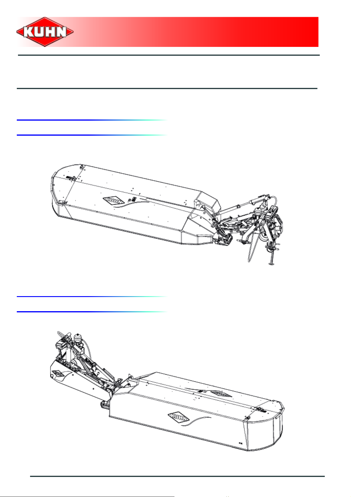
1. Front view
Disc mower
GMD350 - 350-FF
$Identification of the machine
2. Rear view
4
Identification of the machine
Page 7
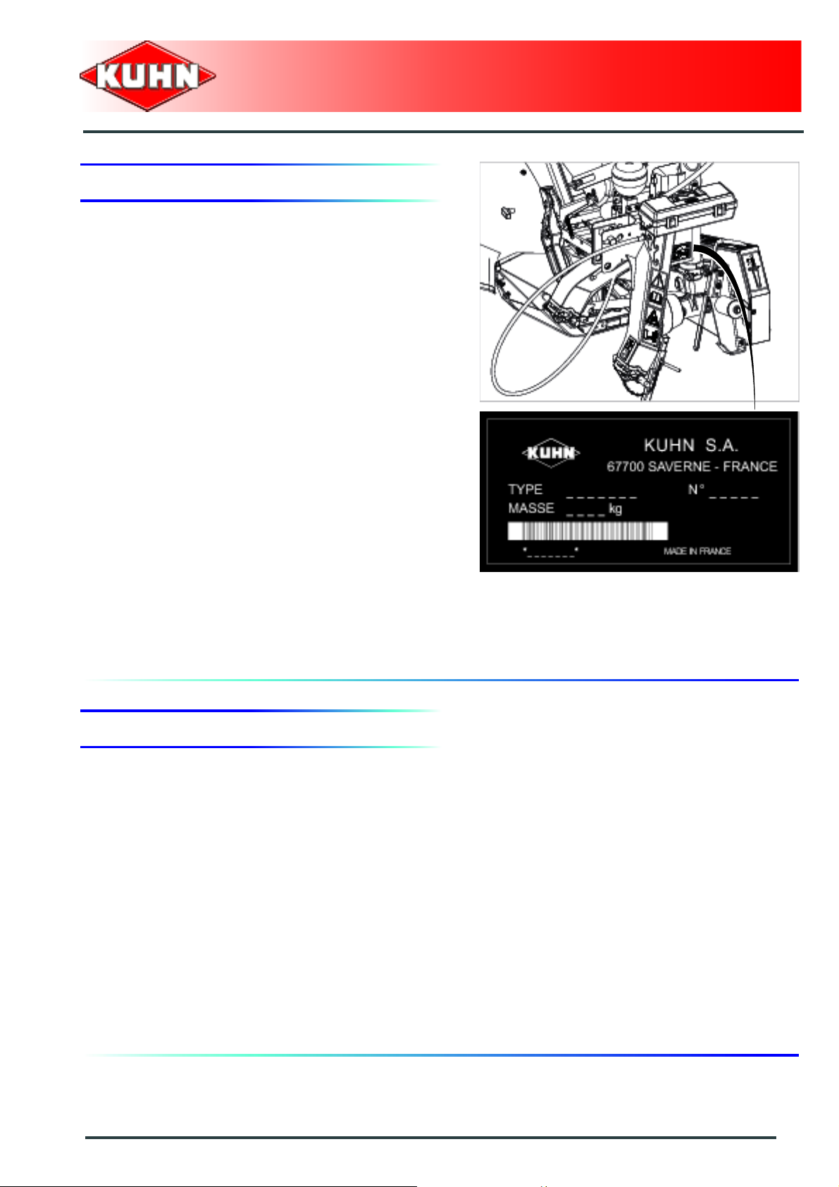
3. Model identification plate
Please write below the type and serial number of the
machine. This information is to be indicated to the dealer
for all spare parts orders.
Type: GMD350
Disc mower
GMD350 - 350-FF
Serial no.:
4. Optional equipment
Tick box corresponding to the equipment fitted on your
machine:
Kit no. A407400: Female coupler.
Kit no. 1066090:Chain stroke limiter.
Kit no. 1066110: Mechanical safety release.
Kit no. 1066120: Mechanical safety release + Hydraulic pivot
Kit no. 1066100: Outer guard hydraulic locking.
Kit no. 1066150: Side deflector.
Kit no. 1066170: 1000 min
-1
drive kit.
Identification of the machine
5
Page 8

$Safety
1. Description of symbols used in this document
This symbol indicates a potentially hazardous situation
that if not avoided, could result in serious bodily injury.
Disc mower
GMD350 - 350-FF
This symbol is used to identify special instructions or
procedures which, if not followed strictly, could result in
machinery damage.
This symbol is used to communicate technical
information of particular interest.
6
Safety
Page 9

Disc mower
GMD350 - 350-FF
2. Safety instructions
Introduction
The machine must only be operated, maintained and repaired by competent persons who are familiar with
machines' specifications and operation and aware of safety regulations fo r preventing accidents.
The operator must imperatively respect safety instructions in this manual and in the warnings posted on the
machine. The operator is also obliged to respect current le gislation concerning accident prevention, wo rk safety
and public traffic circulation.
Designated use of the machine also means following operation, maintenance and repair recommendations
given by the manufacturer, and using only genuine spare parts, equipment a nd acce sso ries, as r ecom mended
by the manufacturer.
The manufacturer is not held liable for any damage resulting from machine applications other than those
specified by the manufacturer. Any use other than the designated operation is at the risk and responsibility of
the operator.
The manufacturer is not held liable for any damage or accident re sulting from machine modifications carried out
by the operator himself or by a third party without previous written agreement from the manufacturer.
Read and follow the safety instructions
Before using the machine, carefully read all the safety
instructions in this manual and the warnings placed on
the machine.
Before starting work, the operator must be familiar with
all machine controls, handling devices and their
functions. It is too late to learn once work has been
started!
Never let anyone operate the machine who is not traine d
to do so.
Should you have any difficulties in understanding certain
parts in this manual, please contact your KUHN dealer.
Precautions to be taken before carrying out
any operations on the machine
Before leaving the tractor or before adjusting,
maintaining or repairing the machine, disengage the
PTO drive, turn off the engine, remove ignition key and
wait until all moving parts have come to a complete stop
and apply park brake.
Safety
7
Page 10
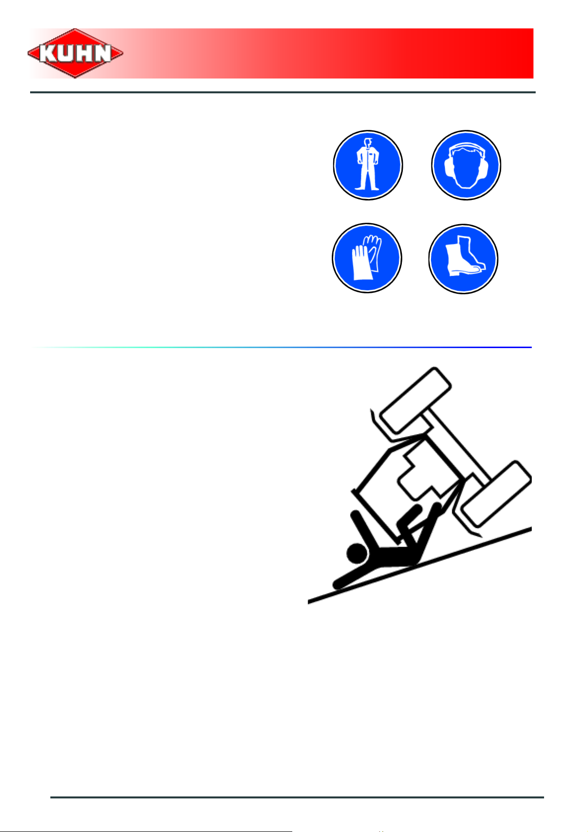
Precautions to take before using the
machine
Do not wear loose clothing which could become caught
up in moving parts.
Wear the appropriate protective clothing for the work in
hand (gloves, shoes, goggles, helmet, ear defenders,
etc.).
Ensure that all operating controls (ropes, cables, rods,
etc) are placed so as they cannot be operated
unintentionally and cause damage or injury.
Before operating the machine, check tightness of nuts
and bolts, particularly on fixing elements (tines, forks,
blades, knives, etc). Retighten if necessary.
Before operating the machine, ensure that all the safety
guards are firmly in place and in good condition.
Immediately replace any worn or damaged guard.
Disc mower
GMD350 - 350-FF
Precautions when driving
Tractor handling, stability, performance and braking
efficiency are all affected by weight distribution, trailed or
mounted implements, additional ballast and driving
conditions. It is therefore of great importance that the
operator exercises caution in every given situation.
Groundspeed must be adapted to ground conditions as
well as to roads and paths. Always avoid abrupt change s
of direction.
Be particularly cautious when turning corners, paying
attention to machine overhang, length, height and
weight.
Never use a narrow track tractor on very uneven or
steeply sloping ground.
Never leave the tractor seat while the machine is
operating.
Carrying people or animals on the machine when
working or in transport is strictly forbidden.
8
Safety
Page 11
Precautions when driving on public roads
Dimensions
Depending on the dimensions of the machine, contact
the relevant authorities to ensure that it can be legally
transported on public roads.
If the machine is over the maximum legal size, follow the
local regulations for special transportation of oversize
equipment.
Transport position
Before transporting the machine on public roads, place
the machine into its transport position, according to the
instructions in this manual.
Lights and indicators
Before transporting the machine on public road s, ensure
that all legally required lightings and signallings are in
place.
Ensure that lightings and signallings are clean and in
good working order. Replace any missing or broken
equipment.
Disc mower
GMD350 - 350-FF
Always obey current regulations for driving
on roads.
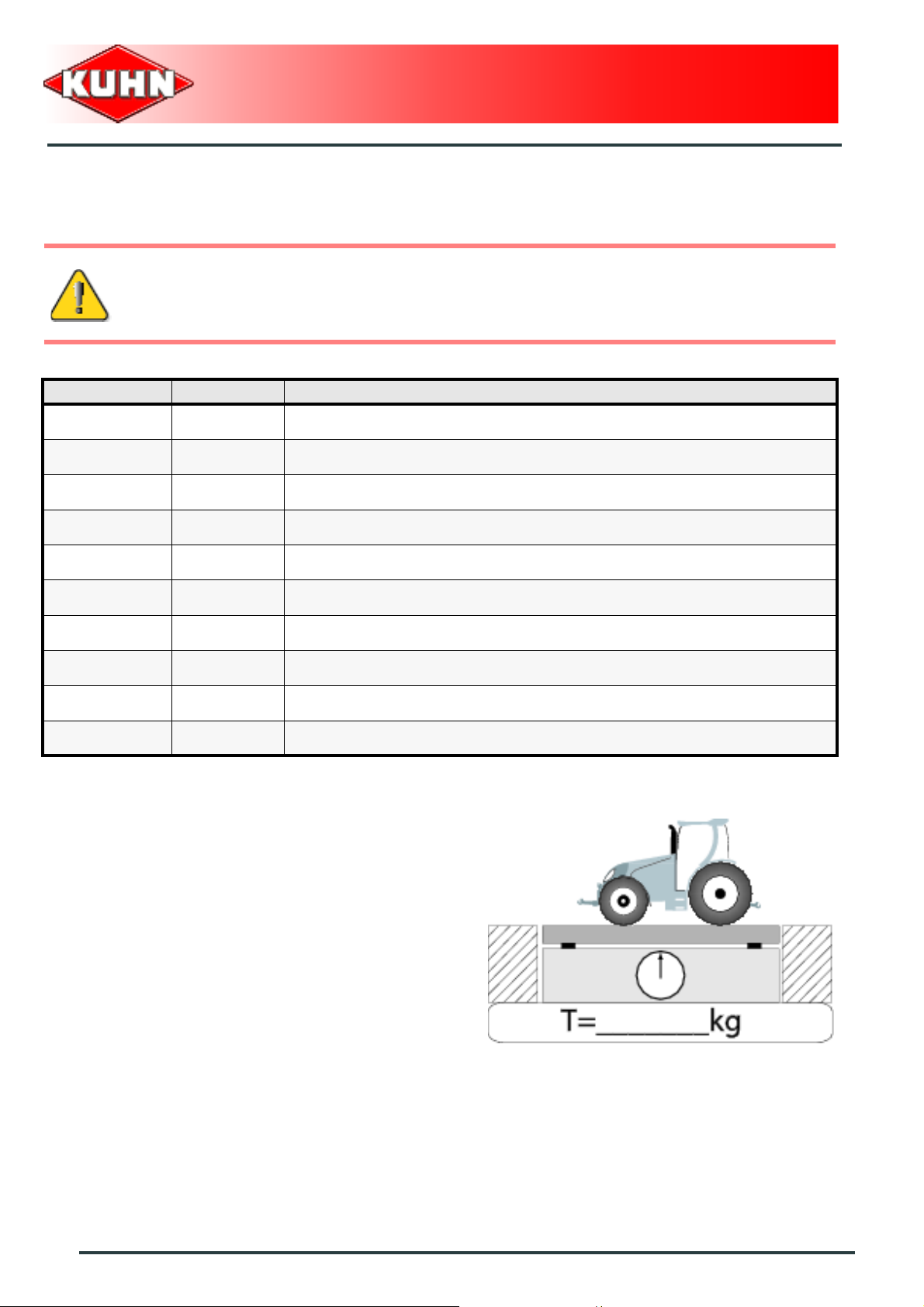
Gross weight and weight per axle
The drawings are not legally binding, their only aim is to illustrate the method to use.
Prior to driving on public roads, check t hat criteria are met t o be in conformity with the count rie's
regulations:
- When coupling a tool to the front and rear 3-point lift linkage, the maximum authorized
payload must not be exceeded.
- When coupling tools to the front and rear 3-point lift linkages, the maximum load on each
axle's tires must not be exceeded.
- The load on the tractor front axle must always repr esent 20 % of the tr actor unladen we ight.
Safety
9
Page 12
For machines with hoppers or tanks:
- If the total unit weight exceeds the tractor Gross Combined Weight Rating in accordance
with the countrie's legislation, empty the hopper to travel on public roads.
- In any case, we recommend to travel on public roads with empty hoppers and tanks.
Description of symbols
Description Units Description
T kg Tractor unladen weight
PTAC kg Gross Combined Weight Rating
T1 kg Unladen load on tractor front axle
T2 kg Empty load on tractor rear axle
Disc mower
GMD350 - 350-FF
t kg Axle loads (Tractor + machine)
t1 kg Load on front axle (Tractor + machine)
t2 kg Load on rear axle (Tractor + machine)
t1 max kg Maximum load authorized on the tractor front axle according to the tires
t2 max kg Maximum load authorized on the tractor rear axle according to the tires
M1 kg Total weight of front tool or front ballast
Stage 1:
To measure:
- Tractor tare (T).
10
Safety
Page 13
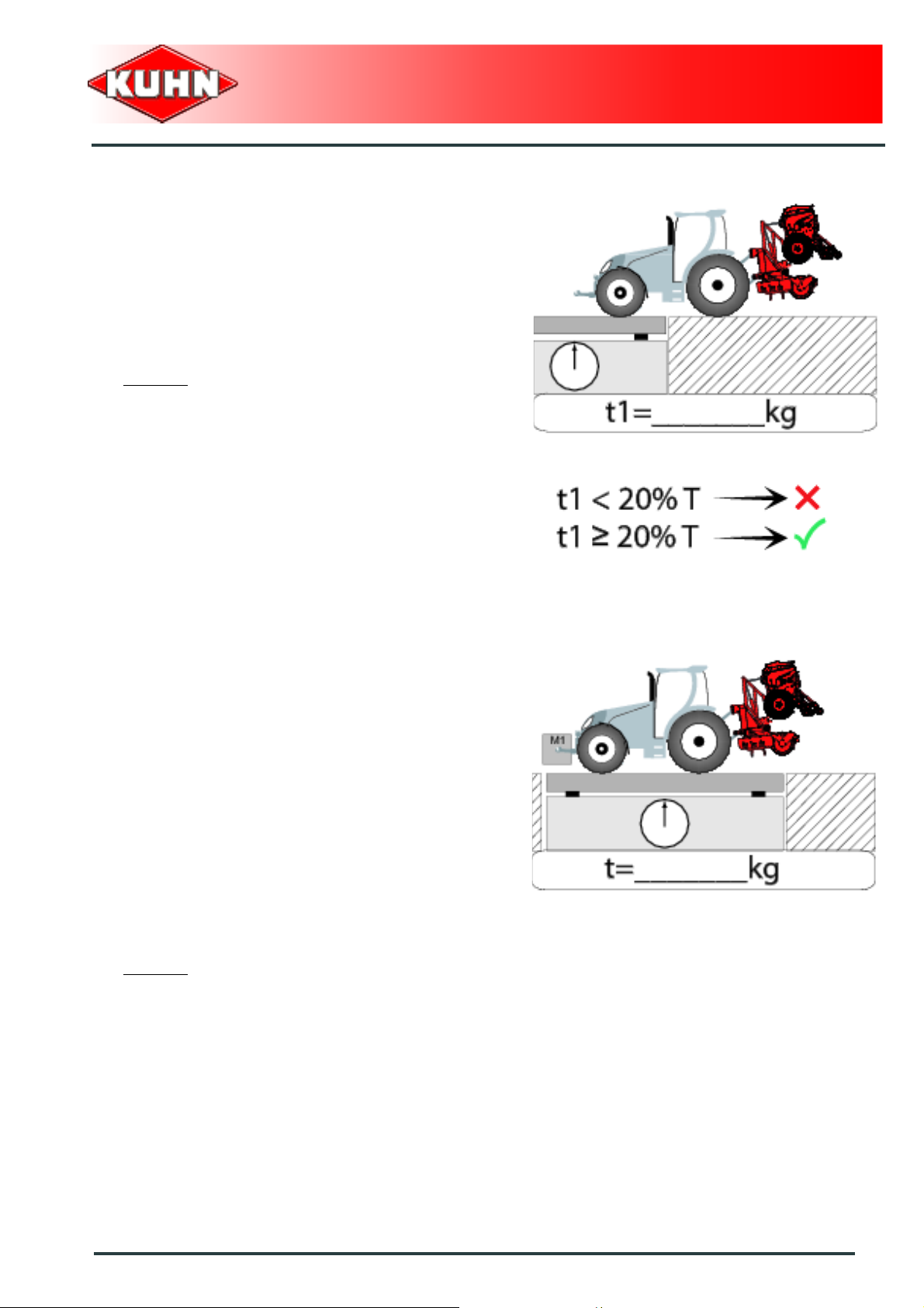
Stage 2:
- Couple the machine to the tractor.
To measure:
- Load on front axle (t1):
• Tractor + machine (transport position).
To do:
- If the front axle load (t1) is below 20% of the tractor
tare (T), add ballast weights (M1) to exceed the
minimum load on the front axle.
Example:
• (T) = 7500 kg (16535 lb)
• The front axle load must be of minimum 1500 kg
(3300 lb).(20% of T)
• (t1) = 700 kg (1545 lb).
• 700 kg (1545 lb) < 1500 kg (3300 lb).
• Add ballast weights until the minimum front axle
load is exceeded.
• Repeat checking procedure.
Disc mower
GMD350 - 350-FF
Stage 3:
To measure:
- Total weight (t):
• Tractor + machine (transport position).
• Ballast weights.
Checking:
- To go to the next stage:
• Check in the tractor's operator's manual that the
value measured is below the tractor's Gross
Combined Weight Rating.
To do:
- If t < PTAC go to the next stage.
- If the total unit weight exceeds the tractor Gross
Combined Weight Rating in accordance with the
countrie's legislation, empty the hopper to travel on
public roads.
Example:
• (t) = 10000 kg (24250 lb)
• PTAC = 13000 kg .
• t < PTAC : Go to the next stage.
Safety
11
Page 14

Stage 4:
To measure:
- Load on rear axle (t2):
• Tractor + machine (transport position).
• Ballast weights.
Checking:
- Check in the tractor's operator's manual that the value
measured is below the maximum allowed tractor rear
axle load.
- Check that tyre and rim specifiations are in conformity
with the requirements of the tractor manufacturer.
Example:
• Load on rear axle (t2) = 8500 kg (18740 lb)
• Check in the tractor's operator's manual that the
value measured is below the maximum allowed
tractor rear axle load.
• Check that tyre and rim specifiations are in
conformity with the requirements of the tractor
manufacturer.
Disc mower
GMD350 - 350-FF
Maximum speed
Always keep to the legal speed limit for driving a tractormachine assembly on public roads.
12
Safety
Page 15
Precautions when coupling
Before attaching the machine, make sure that it cannot
accidentally start moving (chock the wheels) and that the
parking stand is in the right position.
The machine must only be attached to the hitch points
provided for this purpose.
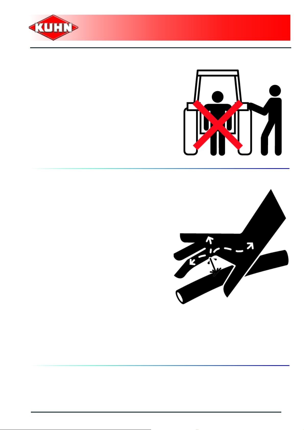
Never stand between the tractor and the machine when
operating the three point linkage.
Do not stand between the tractor and the machine
without ensuring that the parking brake is applied.
Disc mower
GMD350 - 350-FF
Hydraulic circuit
Caution! The hydraulic circuit is under high pressure.
Maximum pressure at work: 200 bar (2900 psi).
Before connecting hoses to the tractor hydraulics,
ensure that tractor and machine circuits are not under
pressure. Before disconnecting a hose, depressurize the
hydraulic circuit.
To avoid making incorrect connectio ns, mark hydraulic
couplers and corresponding hoses with colors.
WARNING! Functions could be reversed (for example:
lift/lower) and cause accidents.
Regularly check the hydraulic hoses. In case of normal
wear, replace the hydraulic hoses every 5 years.
Damaged or worn hoses must immediately be r eplaced.
When replacing the hydraulic hoses, only use hoses with
the specification recommended by the manufacturer of
the machine.
To locate a leak, use appropriate means. Protect body
and hands from liquid under pressure.
Any liquid under pressure (particularly oil from
hydraulics) can penetrate the skin and cause severe
injury. If injured, see a doctor immediately, there could
be danger of infection.
Before any adjustments, maintenance or repairs are
carried out, lower the machine to the ground,
depressurize the hydraulics, turn off the engine, remove
ignition key and wait until all moving parts have come to
a complete stop.
Safety
13
Page 16

PTO shaft
Use only PTO shafts supplied with the machine or
recommended by the manufacturer.
The protective shield of the tractor PTO stub, the PTO
shaft guards and the protective covering of the machine
input shaft must always be in place and in good
condition.
Make sure that the PTO shaft guards are secured with
the safety chains provided.
Any worn or damaged guards must be replaced
immediately. A worn guard or an unpro tecte d PTO shaft
can cause a serious or even a lethal accident.
Do not wear loose clothing that could be caught in the
rotating PTO shaft.
Before attaching or removing a PTO shaft, or before
doing any work on the machine, disengage the PTO
drive, turn off the engine, remove ignition key and wait
for all moving parts have come to a complete stop.
If the primary PTO shaft is equipped with a slip clutch or
a free wheel, these must be fitted on the machine side.
Ensure that the PTO shaft is always correctly fitted and
locked into place.
Before connecting the PTO shaft, ensure that the PTO
speed (rotational frequency) and directions of rotation
are in line with manufacturer's recommendat ion s.
Before engaging the PTO drive, make sure all people
and animals are clear from the machine. Never engage
the PTO drive when the tractor engine is stopped.
When uncoupling the machine, rest the PTO shaft on the
support specially provided, and replace protective cover
on the PTO stub of the tractor.
Read and follow the instructions in the operator's manual
provided with the PTO shaft.
Disc mower
GMD350 - 350-FF
14
Safety
Page 17

Precautions during manoeuvres
When moving the machine from the transport position to
the working position and vice versa, make sure that
nobody is within the machine pivoting area.
Remote controlled components
Danger of crushing and shearing can exist when
components are operated by hydraulic or pneumatic
controls. Keep away from these danger zones.
Safety decals
Safety warning decals are placed in pictorial form on
various parts of the machine. They are there to warn you
of potential dangers and to tell you how to avoid
accidents.
Always keep the safety decals clean and readable, and
replace them when they are worn, damaged, missing or
illegible.
Disc mower
GMD350 - 350-FF
Waste disposal
Respect the environment! Never spill pollutants (oil,
grease, filters, etc.) on the ground, never pour them
down the drain and never discard them in any other
place where they could pollute the environment. Never
throw away or burn a tyre. Always take waste to
specialized recycling or waste disposal centers.
Safety
15
Page 18

Precautions for maintenance and repair
work
Before leaving the tractor or before adjusting,
maintaining or repairing the machine, disengage the
PTO drive, turn off the engine, remove ignition key and
wait until all moving parts have come to a complete stop
and apply park brake.
Rest the machine on the gr ound, release the pressure
from the hydraulic circuit and leave the machine to cool
down.
Make sure that the parts of the machine that need to be
lifted for maintenance or repair work are firmly propped
up.
Before any work is done on the electric circuit or before
any electric welding is carried out on the attached
machine, disconnect the machine from the tractor
electrical circuit. Also disconnect alternator and battery
terminals.
Repairs on elements under pressure or tension (springs,
pressure accumulators, etc.) must only be carried out by
competent persons with regulation equipment.
Wear the appropriate protective clothing for the work in
hand (gloves, shoes, goggles, helmet, ear defenders,
etc.).
Do not solder, weld or use a blow torch near fluids under
pressure or inflammable products.
For your own safety and for correct machine operation,
only use original manufacturer parts.
It is strongly recommended to have your machine
checked by your Kuhn dealer after each season,
especially tools and their attaching hardware.
Disc mower
GMD350 - 350-FF
Projection of stones and foreign objects
For driver safety, always use a tractor equipped with a
cab. Keep the ground to mow free of foreign bodies.
Avoid mowing on stony or rocky grounds. If this is not
possible, take extra safety precautions, such as:
- Fit polycarbonate screens inside the tractor cab's side
and rear windows, or install narrow mesh guards on
their exterior.
- Increase the cutting height to avoid contact with
stones or rocks.
Never start the machine when there are people nearby.
Even when the machine is used in accordance with its
purpose, objects may be projected. Stones and other
foreign objects projected by the moving parts can travel
a considerable distance. Keep all persons and animals
away from the danger zone.
16
Safety
Page 19

The protection covers help reducing risks of projections.
Therefore, make sure t hat all mower protection devices
are in place and good condition prior to using the
machine.
Regularly check the condition of th e protection covers.
Immediatly replace any worn, damaged or missing
cover.
Precautions for machine use
After each use, check the cutting tools (discs, knives)
and their attachment hardware in accordance with the
instructions given in the present manual. Immediately
replace any worn, damaged or missing cutting tool or
element. To do this, use the tool outfit supplied with the
machine. For your safety, only use genuine parts !
Regularly check the condition of th e protection covers.
Immediatly replace any worn, damaged or missing
cover. Before engaging the PTO, rest the cutterbar on
the ground. Make sure all the guards are in place. Keep
all persons and animals away from the danger zone.
Stay a safe distance from the machine when the cutting
tools are in movement.
Never work in reverse.
After disengaging the PTO drive, cuttings tools can
continue rotating for some time. Stay away from the
machine until all moving parts have come to a complete
standstill.
If the machine hits an obstacle, disengage the PTO
drive, stop the tractor engine, remove the ignition key
and wait for all moving parts to come to a complete
standstill. Check the entire machine for any damage
before resuming work.
Disc mower
GMD350 - 350-FF
Safety
17
Page 20
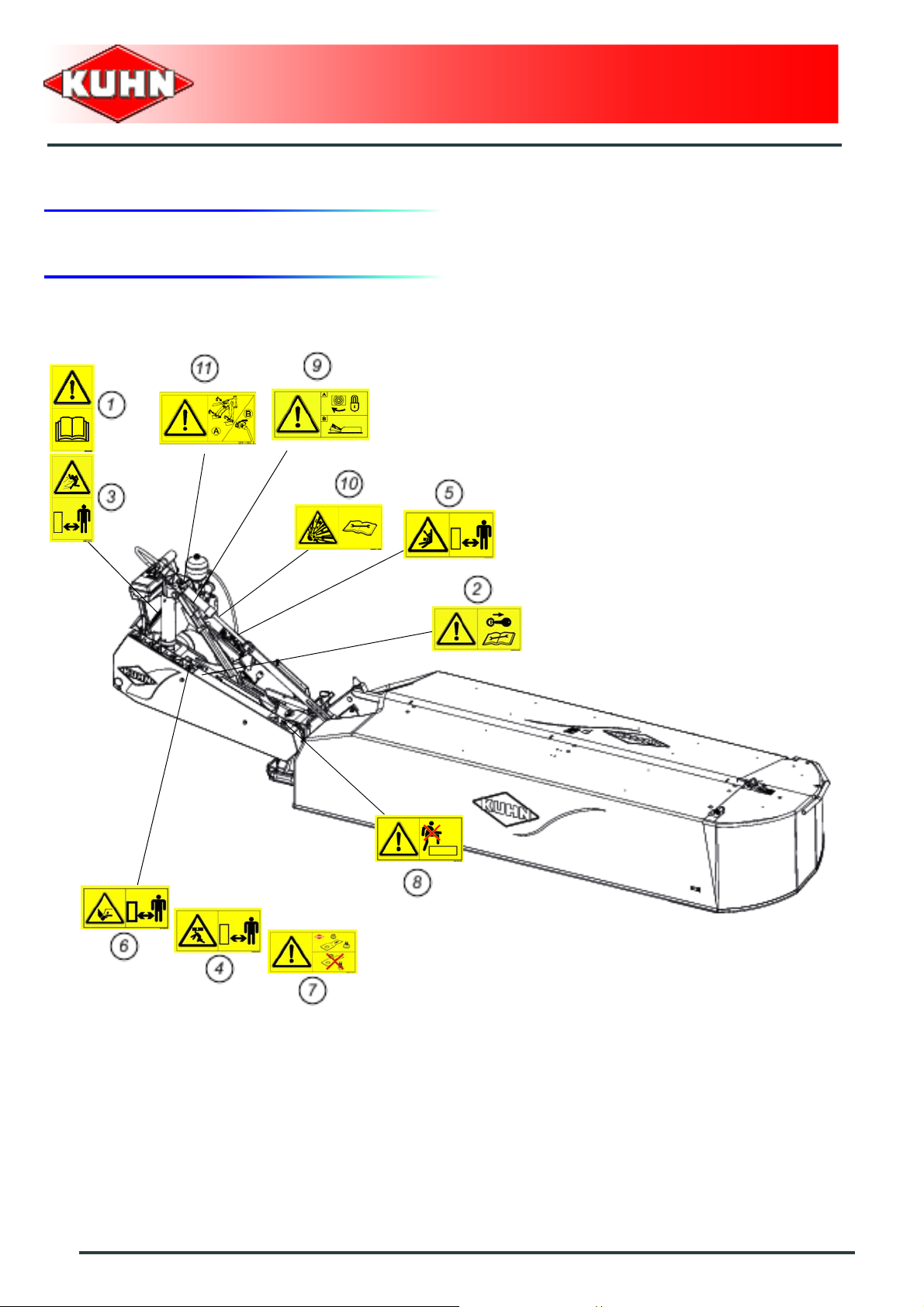
3. Location and description of safety decals on the machine
Location of safety decals
Disc mower
GMD350 - 350-FF
18
Safety
Page 21
Description of safety decals
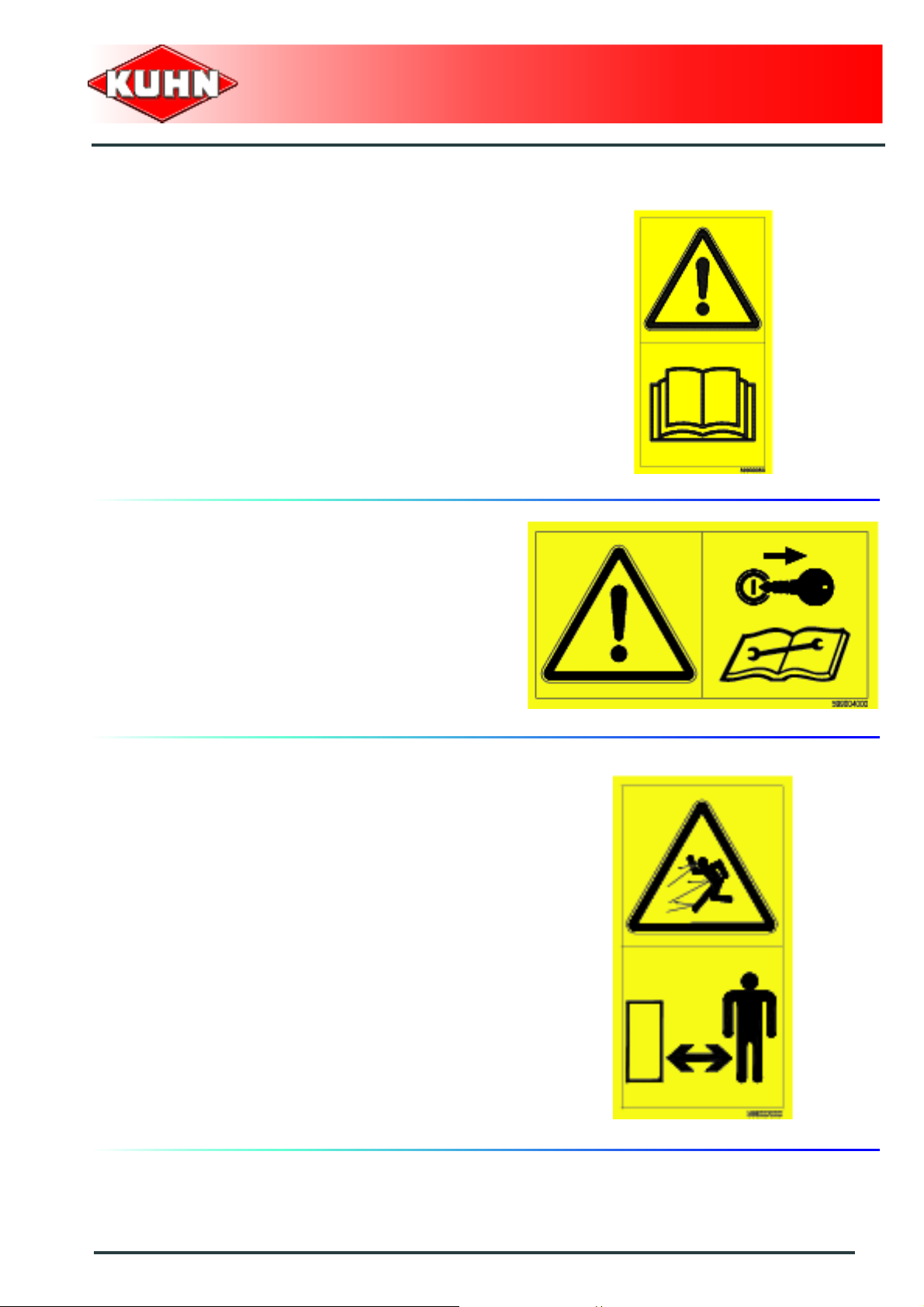
Operating instructions (1)
The operators' manual contains all the information
necessary for using the machine safely. It is imperative
to read and comply with all instructions.
Working on the machine (2)
Disc mower
GMD350 - 350-FF
Before leaving the tractor or before adjusting,
maintaining or repairing the machine, disengage the
PTO drive, turn off the engine, remove ignition key and
wait until all moving parts have come to a complete stop
and apply park brake.
Projections (3)
Stones and other debris projected by the moving parts
can travel a long distance. The protection covers must
always be in position and in good condition. Always stay
at a safe distance from the machine.
Safety
19
Page 22
Crushing area (4)
Never operate in an area where there is a crushing risk
before all moving parts have come to a complete stop.
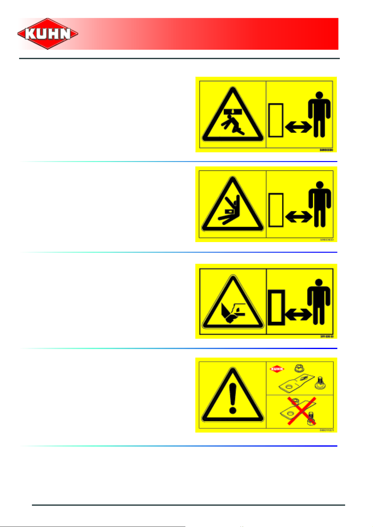
Manoeuvring area (5)
Stay a safe distance from the machine. Crushing hazard.
Disc mower
GMD350 - 350-FF
Rotating cutting tools (6)
Keep away from the mower knives all the time the engine
is running, the PTO drive engaged and the moving parts
have not come to a complete stop.
Cutting tools (7)
The cutting tools and their attachment hardware meet
safety and reliability criteria set by standards and by the
manufacturer. For your own safety and for correct
machine operation, only use original manufacturer parts.
20
Safety
Page 23
Do not step on the machine (8)
Do not step on the machine : Risk of falling or damaging
the protection device.
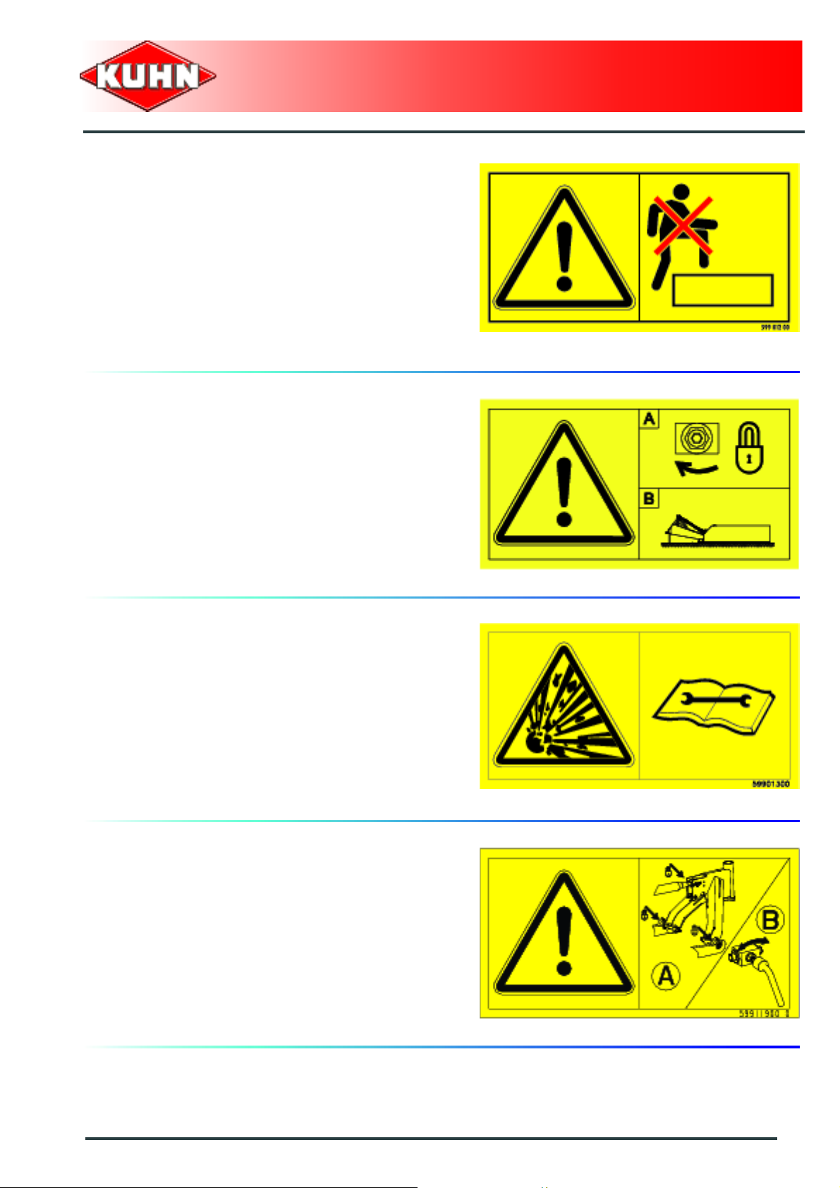
Ground pressure cylinder locking (9)
The ground pressure cylinder valve must be shut off prior
to uncoupling the machine. The ground pressure
cylinder valve must remain closed during the machine
uncoupling.
Disc mower
GMD350 - 350-FF
Danger accumulator (10)
The hydraulic accumulator contains gaz and oil under
pressure. To park the machine or carry out maintenance
work, conform with the instructions given in the
operator's manual
Prior to opening the ground pressure circuit valve (11)
- Attach and lock the machine to the tractor A-frame
prior to opening the ground pressure circuit valve.
Safety
21
Page 24
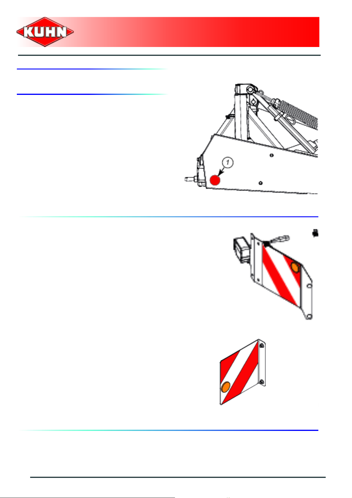
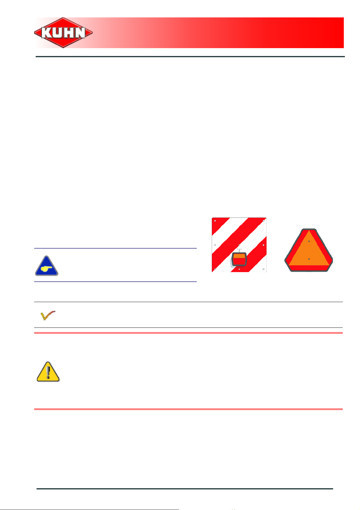
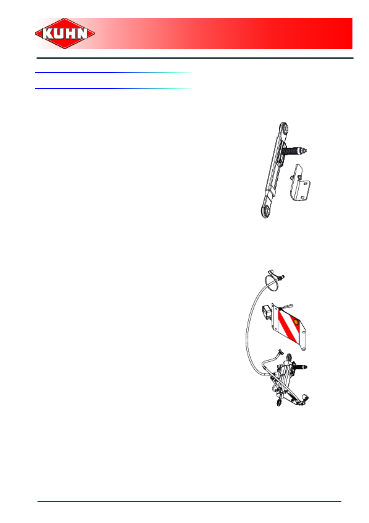
4. Road safety equipment and recommendations
The road safety equipment is mounted in the factory or
by your authorized Kuhn dealer according to current
safety regulations.
The device is composed of:
- 1 red reflector (1).
Always keep to the legal speed limit for driving a tractormachine assembly on public roads. Whatever this
speed, we recommend, for everyone's safety, not to
exceed a speed of 40 km/h (25 mph).
Disc mower
GMD350 - 350-FF
Instructions specific to France
Kit no. 1066130
The machine can be fitted with specific signalling lights
to comply with the road regulations.
Lateral signalling equipment
Kit no. 1066140
+
22
Safety
Page 25
$Machine specifications
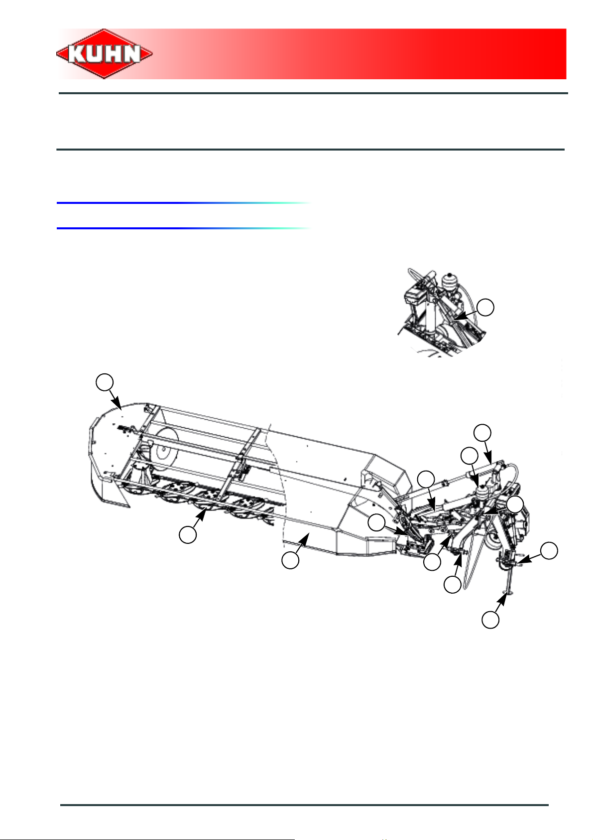
1. Description and glossary
0
Disc mower
GMD350 - 350-FF
2
12
8
7
1
3
1 : Cutterbar 2 : Parking lock
3 : Front guard 4 : Safety breakback
5 : Hydro-pneumatic accumulator 6 : Hitch pin
7 : Gearbox 8 : Lift cylinder
9 : Ground pressure adjustment cylinder 10 : Upper coupling yoke
11 : Parking stand 12 : Side guard
4
9
5
10
6
6
11
Machine specifications
23
Page 26

2. Technical specifications
Attachment type 3 point, Category 2
Number of discs 8
Working width 3.50 m (11’5’’)
Width in working position 5.34 m (17’6’’)
Height in working position 1.39 m (4’6’’)
Length in working position 1.29 m (4’3’’)
Disc mower
GMD350 - 350-FF
Width in transport position 1.62 m (5’3’’)
Height in transport position 3.75 m (12’3’’)
Length in transport position 1.45 m (4’9’’)
Disc rotational speed 2938 min
PTO speed 540 min
Weight:
GMD350
( Fast fit knives )
+ Kit no. 1066120
+ Kit no. 1066100
+ Kit no. 1066130
+ Kit no. 1066140
GMD350
( Knife attachment per bolt and nut )
+ Kit no. 1066110
+ Kit no. 1066130
+ Kit no. 1066140
822 kg (1812 lb)
790 kg (1741 lb)
-1
-1
Minimum PTO power requirement 50 kW (68 hp)
24
Machine specifications
Page 27
3. Required equipment
The machine is factory fitted with the following
equipment:
Put into the working or transport position
- Mechanical safety release.
Disc mower
GMD350 - 350-FF
or
- Mechanical safety release + Hydraulic pivot.
Machine specifications
25
Page 28
Cutter bar
- Knife attachment per bolt and nut.
or
Disc mower
GMD350 - 350-FF
- Fast fit knives.
4. Sound levels
Sound levels have been measured in accordance with the measuring methods as defined in:
NF EN ISO 4254-1
«Agricultural machinery - Safety - Part 1: General requirements»
Weighted equivalent continuous acoustic pressure level at the driver's seat (closed cabin) L (A) eq:
Tractor only: 74.2 dB(A)
Tractor + machine: 76.1 dB(A)
26
Machine specifications
Page 29
$Putting into service
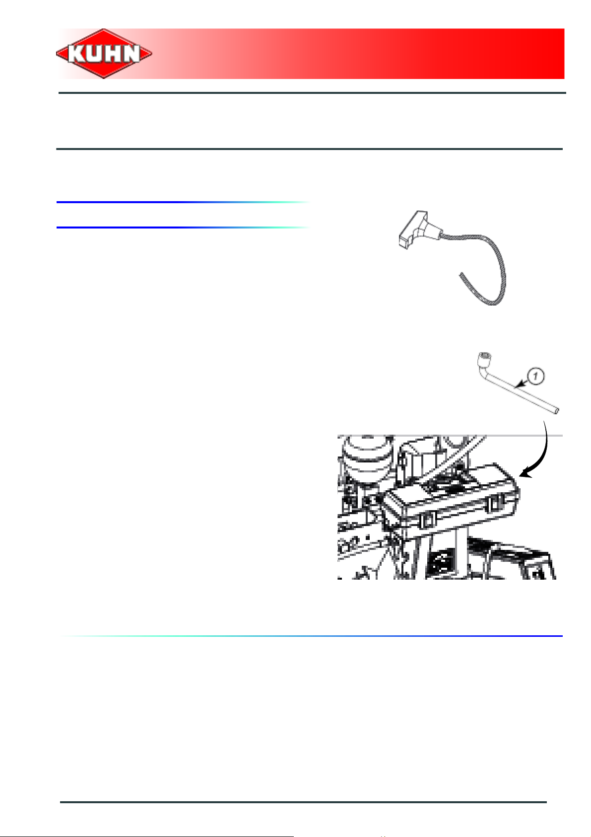
1. Description of control elements
The machine is fitted with a release cord operated from
the tractor cab.
Disc mower
GMD350 - 350-FF
The machine is supplied with an 18 mm box wrench (1)
to carry out certain adjustment and maintenance tasks.
Putting into service
27
Page 30
2. Coupling and uncoupling
The machine adapts to tractors fitted with a 3 point
linkage category 2.
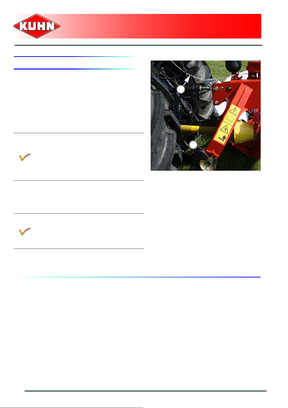
Description of coupling elements
- A PTO shaft 1 3/8’’ - 6 splines (1).
- A release cord (2).
When the following equipment is fitted:
Mechanical safety release + Hydraulic pivot
- 1 hydraulic hose controlling the machine
transport/work position cylinder.
- 1 hydraulic hose pressurizing the mowing
unit pivot cylinder.
Disc mower
GMD350 - 350-FF
2
1
or
When the following equipment is fitted:
Mechanical safety release
- 1 hydraulic hose controlling the machine
transport/work position cylinder.
28
Putting into service
Page 31

Preparing the tractor
Check that the tractor's authorized gross
weight as well as its lift capacity and
maximum weight per axle are not exceeded.
The front axle load (1) must never, under any
circumstances, be less than 20% of the
tractor's unladen weight. Add ballast weight s
to the front in order to preserve the steering
and braking efficiency.
-
The tractor must be fitted with lower link
stabilizers.
-
The tractor PTO stub must rotate at a speed of 540 min-1.
Disc mower
GMD350 - 350-FF
When the following equipment is fitted:
Mechanical safety release + Hydraulic pivot
The tractor must be fitted with a double acting
hydraulic outlet with float position.
or
When the following equipment is fitted:
Mechanical safety release
The tractor must be fitted with a single acting
hydraulic outlet with float position.
Putting into service
29
Page 32

Preparing the machine
Disc mower
GMD350 - 350-FF
Positioning of lower links
- Measure dimension E.
- Adjust tractor lower link stabilizers to measure E =
50 mm (2").
Linkage adjustment
- Measure dimension A.
E
If measure A is below 2.10 m (6’11’’):
- Place lower links in position a:
Adjust machine lower hitch pin position:
- Loosen the 8 screws (3).
- Position hitch pin (1) at measure F = 10 mm (0.4").
- Tighten 4 hitch pin screws (1).
• Torque : 12 daN m (89 lbf ft).
- Position hitch pin (2) at measure (X = 825 mm (2’8").
- Tighten 4 hitch pin screws (2).
• Torque : 12 daN m (89 lbf ft).
A
F
X
30
Putting into service
Page 33

If measure A is comprised between 2.10 m (6’11")
and 2.25 m (7’04"):
- Place lower links in position b:
Adjust machine lower hitch pin position:
- Loosen the 8 screws (3).
- Centre hitch pin (1) with regards to the mounting plate.
- Tighten 4 hitch pin screws (1).
• Torque : 12 daN m (89 lbf ft).
- Position hitch pin (2) at measure (X = 825 mm (2’8").
- Tighten 4 hitch pin screws (2).
• Torque : 12 daN m (89 lbf ft).
If measure A is comprised between 2.25 m (7’04")
and 2.40 m (7’10"):
- Place lower links in position c:
Adjust machine lower hitch pin position:
- Loosen the 8 screws (3).
- Position hitch pin (2) at measure G = 10 mm (0.4").
- Tighten 4 hitch pin screws (2).
• Torque : 12 daN m (89 lbf ft).
- Position hitch pin (1) at measure (X = 825 mm (2’8").
- Tighten 4 hitch pin screws (1).
Torque : 12 daN m (89 lbf ft).
Disc mower
GMD350 - 350-FF
X
G
X
Putting into service
31
Page 34

Pressurizing the hydraulic ground pressure circuit
The machine hydraulic ground pressure
circuit is factory set without pressure.
The optimal suspension is obtained with the mowi ng unit
ground pressure set to the minimum, in such a way that
the unit does not lift off the ground when going over
irregular ground contours.
- Couple the machine to the tractor
• ( See section: Coupling the machine ).
- Lower tractor lift linkage until obtaining a distance of
450 mm (1’5’’) between the hitch pin pivot point and
the ground.
- Open valves (1) using 18 mm box spanner:
• (a) Hydraulic valve bank.
• (b) Ground pressure circuit.
- Activate the transport/work cylinder control valve in
the "pivot into transport" position.
- Check the pressure increase indication on the ga uge .
- Shut-off valve of the hydraulic valve bank when the
pressure reaches 105 bar (1523 psi) on the gauge
Disc mower
GMD350 - 350-FF
1
1
Conventional pressure = 105 bar (1523 psi)
Hydraulic valve:
- Valve open (a)
- Valve closed (b)
Ground pressure circuit valve:
- Valve open (a)
- Valve closed (b)
32
Putting into service
Page 35

Coupling the machine
- Lower the tractor three-point linkage.
- Position ball joints of tractor lower links in line with
machine lower yokes.
- Attach the lower links to the hitch pins.
- Secure each hitch pin with lynch pin.
Check that the top link is attached to one of the
upper holes on the tractor side.
Disc mower
GMD350 - 350-FF
- Attach the top link to the machine top hitch pin.
- Insert and lock top link lynch pin.
- Place release cord handle in the tractor cab.
- Lift machine using tractor hydraulic lift linkage.
- Fold and lock parking latch (1) using spring (2).
The parking latch must always be locked for
work and transport.
1
2
Putting into service
33
Page 36

- Raise and lock parking stand (1).
The following procedure puts the machine
mechanism under tension and balances
plays in the tractor-mechanism coupling
links.
Prior to opening the ground pressure circuit
valve:
- Attach the lower links to the hitch pins.
- Attach the top link to the hitch pin.
Disc mower
GMD350 - 350-FF
1
- Open the ground pressure cylinder valve (1) using 18
wrench.
1
34
Putting into service
Page 37

The machine is properly attached when the following conditions are respected:
Disc mower
GMD350 - 350-FF
- Pivot pin (1) is vertical.
If pivot pin (1) is not vertical:
- Adjust and lock the tractor turnbuckles.
• Fully lift tractor lift linkage.
• Shut-off the mowing unit ground pressure circuit
valve (2) using 18mm box spanner.
• Unlock and unfold parking lock (3) on the bevel
gearbox.
• Lower the tractor three-point linkage.
• Adjust the tractor left levelling rod according to the
difference in height (Avoid loosening the tu rn bu ckle
too much).
Hydraulic connections
When the following equipment is fitted:
Mechanical safety release + Hydraulic pivot
2
3
1
- Connect the hydraulic hose of the
transport/work cylinder to a double acting
valve with float position.
- Connect the mechanical safety release
hose with hydraulic pivot to the same
double acting valve.
When the following equipment is fitted:
Mechanical safety release
- Connect hydraulic hose (1) of the
transport/work cylinder to a single acting
valve with float position.
Putting into service
35
Page 38

Electrical connection
Lighting and signalling:
When the following equipment is fitted:
Mechanical safety release + Hydraulic pivot
Lighting and signalling:
- Connect 7-pin plug to the tractor.
When the following equipment is fitted:
Mechanical safety release
When optional equipment is used, follow specific
procedures mentioned in the related section:
- Lighting and signalling
Disc mower
GMD350 - 350-FF
Chain stroke limiter
When optional equipment is used, follow specific
procedures mentioned in the related section:
- Chain stroke limiter.
36
Putting into service
Page 39

Primary PTO shaft
Make sure that the PTO shaft is correctly
adjusted, to avoid premature wear and tear.
The tractor PTO stub must rotate at a speed of 540 min-1.
Separate the two half PTO shafts and connect them to
the machine's input shaft and to the tractor PTO stub.
Check the length of the PTO shaft:
Proceed with checks with the mowing unit
lowered and pivoted frontwards.
- When the PTO shaft is in its maximum overlap
position (retracted), tubes should not butt against the
yokes. . As a safety measure, a clearance (L) of at
least 25 mm (1’’) must be maintained.
- When the PTO shaft is in its maximum extended
position, the tube overlap must be more than
250 mm (10’’).
Disc mower
GMD350 - 350-FF
If this is not the case:
• Mark length (H) to cut when the transmission is the
maximum overlap position.
• Shorten the guard tubes and the transmission tubes
by the same length.
• Bevel and clean the tubes.
• Grease the inside of the outer tube.
Never operate the PTO shaft at an angle X exceeding
30°.
To avoid serious accidents, the PTO drive
shaft guards must be properly in place and
fixed with the chains provided.
Putting into service
37
Page 40

-
On machine side, attach guard chain to the ma in frame .
Immediately replace any worn or damaged
guard.
Adjusting the machine
Frame height
Tractor fitted with a hydraulic position control function:
- Lower tractor lift linkage in order to engage lift stop (1)
in its housing.
- Lower tractor lift linkage until obtaining a distance of
450 mm (1’5’’) between the hitch pin pivot point and
the ground.
- Make sure that distance A equals at least 3 mm (0.1’’).
- Note the corresponding lever position in the tractor
cab.
Disc mower
GMD350 - 350-FF
Tractor not fitted with a hydraulic position control
function.
When optional equipment is used, follow specific
procedures mentioned in the related section:
- Chain stroke limiter
When the following equipment is fitted:
Mechanical safety release + Hydraulic pivot
- Check that lock valve actuator (1) is no
longer engaged in cam (2).
2
1
38
Putting into service
Page 41

Uncoupling the machine
- Activate the transport/work cylinder to bring the
mowing unit in working position.
- Fully lift tractor lift linkage.
- Shut-off the mowing unit ground pressure circuit valve
(1) using 18mm box spanner.
- Unlock and unfold parking lock (1) on the bevel
gearbox.
Disc mower
GMD350 - 350-FF
1
1
- Lower and lock parking stand (1).
- Unlock tractor lower link stabilizers.
Make sure no foreign material is located on
the bevel gearbox.
Check that there are no foreign bodies in
front of the leg stop.
- Lower the tractor three-point linkage to rest the
machine on the ground.
1
Putting into service
39
Page 42

- Uncouple the PTO shaft.
- Place PTO shaft in holder (1).
When the following equipment is fitted:
Mechanical safety release + Hydraulic pivot
- Disconnect and store hydraulic hoses in
holder (1).
- Disconnect and store lighting equipment 7pin plug in its holder (1).
Disc mower
GMD350 - 350-FF
1
When the following equipment is fitted:
Mechanical safety release
- Disconnect and store hydraulic hose in
holder (1).
1
40
Putting into service
Page 43

- Remove cord from tractor an d store it in its holde r on
the machine (1).
- Detach the top link from the machine end.
- Release the lower links.
Disc mower
GMD350 - 350-FF
1
The machine is uncoupled.
Always park the machine with the cutter bar
in horizontal position.
Never open the ground pressure circuit valve
prior to having coupled the machine to the
tractor lower links and top link.
Putting into service
41
Page 44

When the following equipment is fitted:
Mechanical safety release + Hydraulic pivot
Adjusting the pivot sequence of the
machine
The machine pivot sequence when putting the
machine into work/transport position is
obtained by adjusting cam (2).
- Loosen screws (1).
- Pivot cam (2) according to the required
setting.
To delay the machine pivot sequence, move
cam (2) counterclockwise.
To advance the machine pivot sequence, move
cam (2) clockwise.
Disc mower
GMD350 - 350-FF
2
1
1
1
1
- Tighten screws (1).
• Torque: 5 daN m (37 lbf ft).
Valve holder adjustment:
The oblong holes enable obtaining the valve
actuator disengagement with regards to the cam
when the hitch pins are at 450 mm (1’5’’) from the
ground (3).
42
Putting into service
Page 45

$Instructions for transport
Before placing the machine into transport
position:
Wait until the rotating parts have come to a
complete stop.
Check that nobody is locate d in the machine
pivoting area. If there is someone, make su re
the person moves away.
1. Putting the machine into transport position
Disc mower
GMD350 - 350-FF
From the working position:
When the following equipment is fitted:
Mechanical safety release
- (a) Unlock and lift front guard using 18mm
box spanner supplied with the machine.
- The guard locks automatically.
- (b) Release and lift side guard using 18mm box
spanner supplied with the machine.
• The guard locks automatically.
- Pull release cord until lift stop (1) is free.
- Fully lift tractor lift linkage ( The machine shoe inner
must no longer be in contact with the ground ).
When the following equipment is fitted:
Mechanical safety release + Hydraulic pivot
When putting the machine into transport
position, the cutter bar lifts and pivots
rearwards simultaneously.
Instructions for transport
43
Page 46

- Activate the transport/work cylinder to bring the
mowing unit in transport position.
- As cutter bar is being pivoted, wait until lift stop end (1)
passes over lock (2) and release cord.
The machine automatically locks in transport position.
The machine is in transport position.
Never engage the tractor PTO drive when the
machine is in transport position.
Disc mower
GMD350 - 350-FF
2. Conformity with the road regulations
Before driving the machine on public roads,
ensure that the machine complies with
current highway code regulations.
Check that the retroreflective signalling equipment is
clean before going on public roads.
Replace worn or damaged reflectors.
Make sure the release cord cannot be
operated inadvertently.
44
Instructions for transport
Page 47

Make sure that transport lock (1) is fully
engaged.
Disc mower
GMD350 - 350-FF
Instructions for transport
45
Page 48

$Instructions for work
Before placing the machine in working
position:
- Check that nobody is within the machine
pivoting area.
- If there is someone, make sure the
person moves away.
1. Putting the machine into work position
Disc mower
GMD350 - 350-FF
When the following equipment is fitted:
Mechanical safety release + Hydraulic pivot
When putting the machine in work position,
the cutter bar simultaneously lowers itself
and pivots frontwards.
In order to respect an angle X of 90° between
the tractor and the mowing unit in working
position, always use tractor double acting
valve to lower the mowing unit.
From the transport position:
- Fully lift tractor lift linkage.
- Operate transport/work position cylinder to relieve
pressure on the transport lock.
- Pull the release cord until transport lock is released.
- Lower the mowing unit onto the ground using the
mowing unit lift cylinder.
46
Instructions for work
Page 49

When the following equipment is fitted:
Mechanical safety release
- Unlock and lower the front guard using
18mm box spanner supplied with the
machine.
• The guard locks automatically.
- Unlock and lower side guard.
• The guard locks automatically.
- Shift the mowing unit lift cylinder directional control
valve in float position.
- Lower the tractor lift linkage in working position:
• The distance between hitch pin axis and the ground
must be of 450 mm (1’5’’).
Disc mower
GMD350 - 350-FF
When the following equipment is fitted:
Mechanical safety release + Hydraulic pivot
- Check that lock valve actuator (1) is no
longer engaged in cam (2).
The machine is in working position.
During work, only use the mowing unit lift
cylinder to place the machine in headland
turn position.
2
1
Instructions for work
47
Page 50

2. Adjustments in working position
Before leaving the tractor or before
adjusting, maintaining or repairing the
machine, disengage the PTO drive, turn off
the engine, remove ignition key and wait until
all moving parts have come to a complete
stop and apply park brake.
Cutting height
The desired cutting height is obtained directly by
adjusting the top link length. The height can be adjusted
from 30 to 60 mm (1.1" - 2.4").
To obtain a different cutting height:
- Place the machine in working position.
- Lift the machine chassis using the tractor lift.
Disc mower
GMD350 - 350-FF
- Shut-off the mowing unit ground pressure circuit valve
(1) using 18mm box spanner.
- Lower the tractor lift linkage in working position:
• The distance between hitch pin axis and the ground
must be of 450 mm (1’5’’).
Ground pressure circuit valve:
- Valve open (a)
- Valve closed (b)
- Modify the top link length to alter the machine tilt
angle.
- Check cutting height.
The following procedure puts the machine
mechanism under tension and balances
plays in the tractor-mechanism coupling
links.
- Never open the ground pressure circuit
valve prior to having coupled the
machine to the tractor lower links and
top link.
1
48
Instructions for work
Page 51

- Open the suspension circuit valve.
Ground pressure circuit valve:
- Valve open (a)
- Valve closed (b)
The maximum cutting height (L1 = 60 mm (2.4’’))
is obtained when the discs are parallel to the
ground.
The minimum cutting height must not be below
(L2 = 30 mm (1.1’’)).
Disc mower
GMD350 - 350-FF
Too low a cutting height can lead to:
- Excessive disc and knife wear.
- Crop being contaminated by soil.
- Delay in regrowth.
Reduced or increased ground pressure
The machine hydraulic ground pressure
circuit is factory set without pressure.
See section:
- Coupling and uncoupling
• Pressurizing the hydraulic ground
pressure circuit
Adjustment
The mowing unit suspension is obtained by a hydropneumatic accumulator.
By modifying the accumulator pressure, the mowing unit
ground pressure varies.
Instructions for work
49
Page 52

To check the ground pressure::
- Place the machine in working position.
- Lower tractor lift linkage until obtaining a distance of
450 mm (1’5’’) between the hitch pin pivot point and
the ground.
- Check the pressure given on the gauge:
Conventional pressure = 105 bar (psi).
MINIMUM operating pressure = 95 bar (psi).
MAXIMUM operating pressure = 115 bar (psi).
The pressure must be adapted to the nature and
moisture degree of the ground.
Disc mower
GMD350 - 350-FF
Never adjust machine to a pressure not
comprized between these limit values.
Pressure adjustment
Increase the hydro-pneuma tic accumulator pressure to
reduce the mowing unit ground pressure:
- Place the machine in working position.
- Open valve (1) of hydraulic valve bank using 18mm
box spanner supplied with the machine.
Hydraulic valve:
- Valve open (a) (Adjustment)
- Valve closed (b) (Work and tran sp or t)
- Use mowing unit lift cylinder to lift the mowing unit.
- Check the pressure increase indication on the ga uge .
- When the required pressure is reached, close the
valve.
1
50
Instructions for work
Page 53

Reduce the hydro-pneumatic accumulator pressure to
increase the mowing unit ground pressure
- Place the machine in working position.
- Shift the mowing unit lift cylinder directional control
valve in float position.
- Open valve (1) of hydraulic valve bank using 18mm
box spanner supplied with the machine.
- Check the pressure decrease indication on the gauge.
- When the required pressure is reached, close the
valve.
Hydraulic valve:
- Valve open (a) (Adjustment)
- Valve closed (b) (Work and transport)
Disc mower
GMD350 - 350-FF
1
Swathing system
Swathing system components:
- 1 outer swath wheel.
Check that there is a minimum clearance (J)
of 15 mm (0.59’’) between the cone rib and
the swath wheel.
Instructions for work
51
Page 54

3. Machine use
Before mowing and to reduce risks of
projections, lower the front guard.
Keep all persons and animals away from the
machine danger zone.
When the following equipment is fitted:
Mechanical safety release
- Unlock and lower the front guard using
18mm box spanner supplied with the
machine.
- The guard locks automatically.
Disc mower
GMD350 - 350-FF
- Unlock and lower side guard using 18 mm wrench
supplied with the machine.
- The guard locks automatically.
Never lean or step on the protection cover.
At work, the tractor hydraulic valve must
always be in floating position to ensure good
ground contour adaptation.
Before the machine engages the crop:
- Engage the tractor PTO and slowly increase the
speed up to 540 min
Groundspeed
-1
.
52
Instructions for work
Adapt the forward speed to the working
conditions.
Page 55

Headland turn maneuvers
Operate the cutterbar using the "pivot into
transport/work" position cylinder.
Disc mower
GMD350 - 350-FF
- Activate the transport/work cylinder control valve in
the "pivot into transport" position.
• The cylinder lock (1) bottoms.
When the following equipment is fitted:
Mechanical safety release + Hydraulic pivot
If the cutter bar pivots rearwards during the
first headland turn manoeuvre:
- Check that lock valve actuator (1) is no
longer engaged in cam (2).
- Readjust if necessary:
• See section: Adjusting the pivot
sequence of the machine.
1
2
1
The lift linkage clears simultaneously the
main frame and cutter bar off the ground.
Instructions for work
53
Page 56

Machine safety
When hitting an obstacle:
Before carrying out any maintenance or
repairs on the machine, switch off the trac tor
engine, remove ignition key, wait until all
moving parts have come to a standstill and
apply park brake.
The break-away latch allows the cutter bar to pivot to the
rear when hitting an obstacle.
In case an obstacle has been struck, check
that the mowing unit has not been damaged.
Disc mower
GMD350 - 350-FF
The safety breakback is reset by reversing (a).
54
Instructions for work
Page 57

If the break-away latch releases too easily after reset,
tighten nut (1) to increase spring washer compression
slightly.
Respect spring washer layout.
Basic adjustment:
L= 95 mm (3.7’’)
For normal functioning of th e break-away latch,
measure L must never be below 91 mm (3.60").
Disc mower
GMD350 - 350-FF
In case of clogging:
Before carrying out any maintenance or
repairs on the machine, switch off the tractor
engine, remove ignition key, wait until all
moving parts have come to a standstill and
apply park brake.
- Lift and lock front guard.
- Remove foreign body.
- Check that the mowing unit has not been damaged.
- Check rotating components for damage.
- Lower and lock front guard.
Instructions for work
55
Page 58

$Optional equipment
1. Chain stroke limiter
Kit no. 1066090
This equipment enables adjusting the chassis height in
the absence of a hydraulic stroke limiter with position
indexation on the tractor.
Adjusting the machine
Disc mower
GMD350 - 350-FF
Frame height adjustment
- Lower tractor lift linkage until hitch pins are at a
distance H slightly over 450 mm (1’5’’) from the
ground
- Attach hook of check chain supplied with the machine
in one of the upper holes of the tractor top link yoke.
- Lower the machine until the chain stroke limiter is
under tension.
- The distance between hitch pin axis and the ground
must be of 450 mm (1’5’’).
The tractor lift linkage is in working position.
The frame height is correct when:
- The cutterbar is resting on the ground.
- The chain stroke limiter is tight.
- The lift stop has a functional play of approximately A
= 3 mm (0.1’’) in its housing.
- The 2 hitch pins are parallel to the ground.
- The distance between hitch pin axis and the ground
must be of 450 mm (1’5’’).
- Close hook eyelet with roll pin when properly
adjusted.
1
Uncoupling the machine
Unhook chain stroke limiter (1).
56
Optional equipment
Page 59

2. Outer guard hydraulic locking
Kit no. 1066100
Available for the following models:
- Mechanical safety release + Hydraulic
pivot.
This equipment enables folding the machine o uter guard
using the hydraulic control.
Coupling and uncoupling
Description of coupling elements
Disc mower
GMD350 - 350-FF
- 2 hydraulic hoses pressurizing the outer guard
folding/unfolding cylinder.
Hydraulic connections
- Connect the hydraulic hoses to the pivot cylinder.
Instructions for transport
Putting the machine into transport position
The outer guard folding and cutter bar pivot occur
simultaneously.
Instructions for work
Putting the machine into work position
The outer guard unfolding and cutter bar lowering occur
simultaneously.
Optional equipment
57
Page 60

3. Side deflector
Kit no. 1066150
The side deflectors enables mowing dense or down
crops with long stems.
Fit the side deflector on the cutter bar right attachment
(1).
Disc mower
GMD350 - 350-FF
1
58
Optional equipment
Page 61

4. 1000 min-1 drive kit
Kit no. 1066170
Disc mower
GMD350 - 350-FF
Belt and pulley assembly for tractors with a pto speed of
1000 min
-1
.
5. Adaptation parts
Part no. 56842400 + Part no. 80451046
This equipment enables coupling the machine to a Uframe hitch coupler ( ISO 11001-1 ) ( Quick hitch ).
Optional equipment
59
Page 62

$Maintenance and storage
Before carrying out any maintenance or
repairs on the machine, switch off the trac tor
engine, remove ignition key, wait until all
moving parts have come to a standstill and
apply park brake.
Disc mower
GMD350 - 350-FF
1. Frequency chart
Maintenance intervals are indicated for
normal conditions of use.
Lubrication
Grease:
- The chassis tube
- The chassis lever
When the following equipment is fitted:
Mechanical safety release + Hydraulic pivot
- The cylinder crosshead
Every 50 hours
3
Every 200 hours or at
the end of the season
Oil:
- The moving parts and pivot points
Oil change:
- Gearbox
60
Maintenance and storage
3
3
Page 63

2. Lubrication
Lubricate with multi-purpose grease grade
NLGI 2.
PTO shaft
Primary PTO shaft
- Every 8 hours:
• universal joints (1).
• Free wheel (4)
- Every 20 hours:
• transmission tube (2).
- Every 40 hours:
• guide rings (3)
Disc mower
GMD350 - 350-FF
Place the machine in working position.
Stop the tractor engine and remove ignition
key.
Maintenance and storage
61
Page 64

Grease:
When the following equipment is fitted:
Mechanical safety release + Hydraulic pivot
Disc mower
GMD350 - 350-FF
2
The cylinder crosshead:
Grease the crosshead inside:
- Loosen nut (1) to release lock (2).
- Grease the cylinder tube and sheath inner.
- Fully push the cylinder in the sheath.
- Check that lock is engaged on the nose.
- Tighten nut (1):
• Basic adjustment:
• L= 95 mm (3.7’’)
• See section: ’’Machine safety’’
1
- The chassis tube (2 greasers).
62
Maintenance and storage
Page 65

- The chassis lever (1 greaser).
Disc mower
GMD350 - 350-FF
Oil:
- The moving parts and pivot points.
Maintenance and storage
63
Page 66

- The moving parts and pivot points.
Disc mower
GMD350 - 350-FF
64
Maintenance and storage
Page 67

Oil change:
Gearbox
Disc mower
GMD350 - 350-FF
Before draining oil, operate the machine for a
few minutes so that the oil warms up.
The angle gearbox is lubricated with 0.5 L (0.13 US gal) of SPIRAX A extreme-pressure oil for
mechanical transmissions with viscosity grade SAE 80W90 and API grade GL5.
When draining and refilling, it is recommended to use either a mineral base oil with viscosity grade
SAE 80W90 and API grade GL5, or a synthetic base oil, type PAO (Poly-Alpha-Olefins) with a viscosity
grade equivalent to SAE 80W90.
From the transport position:
- Remove filler plug (1).
- Place a container of sufficient capacity under drain
plug.
- Remove drain plug (2).
- Allow oil to drain completely.
- Wait for dripping to stop.
- Place the cutterbar in horizontal position.
- Pour the correct oil quantity and quality through the
opening of the filler plug (1).
- Check angle gearbox oil level:
- Place the cutterbar in horizontal position.
• The oil level must reach the lower edge of the
emptying hole.
- Clean and reinstall drain plug (2).
- Clean and reinstall the filler plug (1).
1
2
Maintenance and storage
65
Page 68

3. Maintenance
Before carrying out any maintenance or
repairs on the machine, switch off the trac tor
engine, remove ignition key, wait until all
moving parts have come to a standstill and
apply park brake.
Belt tension
Regularly check belt tension and in particular
during the first hours of use.
Disc mower
GMD350 - 350-FF
Never replace belts individually.
Replace belts in full sets.
Adjusting the tension:
- Tighten screw (1) using the 18mm box spanner
supplied with the machine.
- Spacer tube (2) must be in contact with main frame (3)
and washer (4).
During the initial assembly or when installing
a new set of belts, give screw (1) 2 additional
turns to compensate for the inital stretch of a
new set of belts.
2
4
3
1
66
Maintenance and storage
Page 69

Hydro-pneumatic accumulator
Before any work is carried out on a hydraulic
circuit with hydro-pneumatic accumulator,
depressurize the circuit.
It is strictly forbidden to weld, grind or drill
onto a hydro-pneumatic accumulator.
The hydro-pneumatic accumulator does not require any
particular maintenance.
Regularly check the tightness of the accumulator
attachment on the hydraulic valve bank and that no oil
has leaked from the hydraulic circuit (a small oil leak can
change settings).
Disc mower
GMD350 - 350-FF
Depressurize the hydraulic circuit
Suspension hydraulic circuit:
- Stop the tractor engine.
- Shift the mowing unit lift cylinder directional control
valve in float position.
- Open valve (position (a)).
Hydraulic valve:
- Valve open (a) (Adjustment)
- Valve closed (b) (Work and transport)
- Release pressure until the gauge needle reads 0.
- When the pressure reaches 0 bar (0 psi) bar on the
pressure gauge, close the valve (position b .
Pressurizing the hydraulic circuit
See section:
- ’’Pressurizing the hydraulic ground pressure circuit’’.
Maintenance and storage
67
Page 70

Cutterbar
The cutter bar is lubricated for life and does not require regular maintenance.
If in doubt as to the oil quantity contained in the cutterbar, fully drain and refill cutterbar
respecting recommended oil quantity and quality.
Following all service operations or in case of an oil leak, empty an refill cutterbar.
Draining
Before draining oil, operate the machine for a
few minutes so that the oil warms up..
Disc mower
GMD350 - 350-FF
The cutterbar is lubricated with 4.5 L (1.18 US gal) of SPIRAX A extreme-pressure gear oil with viscosity
grade ASX 75W90 and API grade GL5 .
Never use an oil of viscosity SAE 90 in the
cutterbar.
From the working position:
When optional equipment is used, follow
specific procedures mentioned in the related
section:
- Chain stroke limiter.
- Remove filler plug (1) and its seal.
1
68
Maintenance and storage
Page 71

- Activate the transport/work cylinder control valve in
the "pivot into transport" position.
- Place a container of sufficient capacity under drain
plug.
- Remove the inner skid shoe (1) on drive side.
- Unscrew drain plug (1) and its seal.
- Allow oil to drain completely.
- Wait for dripping to stop.
- Clean and reinstall drain plug (1) and its washer.
Replace if necessary.
- Reinstall inner disc skid (2).
• Torque: 12 daN m (89 lbs ft)
- Operate the valve of the transport/work position
cylinder in the working position direction.
Disc mower
GMD350 - 350-FF
1
2
1
- Pour the correct oil quantity and quality through the
opening of the filler plug.
- Clean and reinstall filler plug (1) and its washer.
Replace if necessary.
1
Maintenance and storage
69
Page 72

Check angle gearbox oil level
Regularly check the oil level:
- Place the cutterbar in horizontal position.
- Remove drain plug (1).
- Check the oil level.
- Top up if necessary.
- Clean and reinstall drain plug (1). Replace it if
necessary.
Disc mower
GMD350 - 350-FF
1
Check angle gearbox oil level:
- The oil level must reach the lower edge of the
emptying hole.
70
Maintenance and storage
Page 73

Inspection of knives and securing elements
Immediately replace worn or damaged parts with
genuine KUHN parts.
When the following equipment is fitted:
Knife attachment per bolt and nut
Knives
Inspect systematically all knives before the machine is
operated to:
- guarantee the cutting quality.
- guarantee safety in use.
- Prevent cutterbar damage risks.
Replace knives in the following cases:
- Damaged knives.
Very rough conditions can cause knives to crack and
become deformed.
- Worn knives.
Knife length C must exceed 65 mm (2.6’’).
Knife width B, measured at a distance A of 10 mm (0.4’’)
from the disc edge must exceed 34 mm (1.4’’).
The hole L for the securing bolt must not become oval by
more than 20 mm (0.8’’).
Disc mower
GMD350 - 350-FF
Always replace both knives per disc to avoid
creating an out-of-balance force.
Maintenance and storage
71
Page 74

Fixing elements
Check the fixing elements:
- After hitting an obstacle.
- When replacing knives.
- At the beginning of each season.
The fixing bolts should be changed in the following
cases:
- When there is visible distortion.
- When the locking compound is worn or inoperational.
- When the bolt head wear reaches the center line of
the bolt.
- When diameter D of the bolt shoulder is less than
15 mm (0.6’’).
- After having been removed 5 times.
Disc mower
GMD350 - 350-FF
Replace nuts in the following cases:
- When the contact washer has lost its elasticity.
- When the contact washer loosens itself from the nut.
- When nut wear reaches a = 5 mm (0.2’’).
- After having been removed 5 times.
Check the condition of the fixing elements
regularly and also the torque of the knife-fix ing
bolt: 12 daN m (89 lbf ft).
-
72
Maintenance and storage
Page 75

Knife replacement
Replace knife lock-nuts and bolts when they
have been removed 5 times.
Replace immediately all worn or distorted
knives. Never straighten a bent knife.
Always replace both knives per disc.
- Clean the nut case.
- Place a wooden wedge between two discs to stop
them from rotating.
- Loosen nut using box spanner supplied with the
machine.
- Remove bolt through opening located at the front of
the disc guard.
Knives can be turned over on the same disc to use the
other cutting edge or replaced. On each knife, an arrow
indicates the disc's direction of rotation.
- Make sure that the securing nut and bolt are in good
condition and if necessary, replace them.
- Torque knife locknut to 12 daN m (89 lbf ft).
Dull knives require more horse power and have a
negative effect on the cut quality.
Disc mower
GMD350 - 350-FF
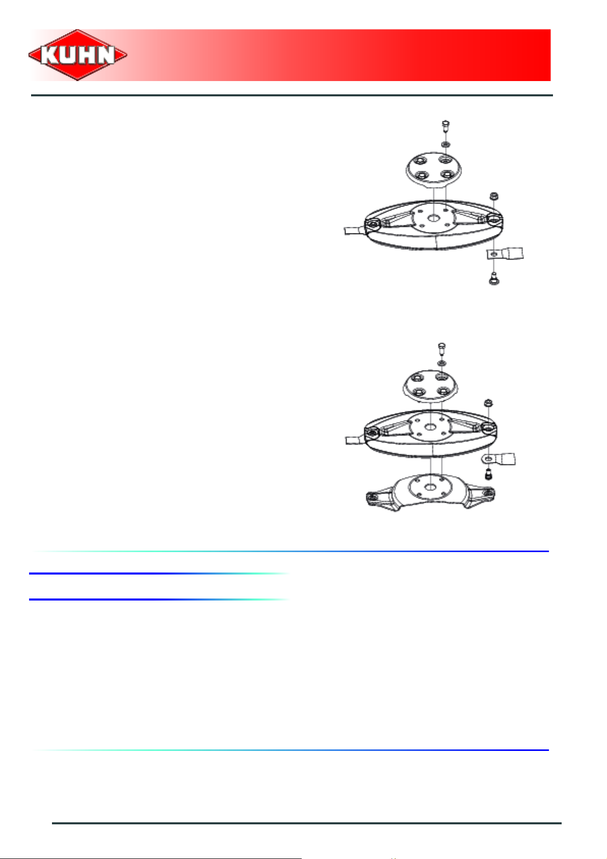
Disc replacement
- Place a wooden wedge (2) between two discs to stop
them from moving.
- Remove 2 bolts (1) and their spring washers using the
box spanner supplied with the machine.
- Remove the disc conical cover.
- Remove the 2 other nipple-screws and their spring
washers.
- Remove the disc.
When remounting:
- Position their largest diameters at right angles to each
other.
- Position conical centre of spring washer at the top.
- Tighten screws:
• Torque: 12 daN m (89 lbf ft).
Maintenance and storage
73
Page 76

Check if there is still a gap of 1 mm (0.04’’)
between the disc lower part and the cutterbar
wear plates.
If this is not the case, fit one (maximum two)
spacer(s) between the disc and the mounting
hub:
- (Part no. 56807100).
Disc mower
GMD350 - 350-FF
74
Maintenance and storage
Page 77

When the following equipment is fitted:
Fast fit knives
Knives
Inspect systematically all knives before the machine is
operated to:
- guarantee the cutting quality.
- guarantee safety in use.
- Prevent cutterbar damage risks.
Replace knives in the following cases:
- Damaged knives.
• Very rough conditions can cause knives to crack
and become deformed.
- Worn knives.
Knife length C must exceed 65 mm (2.6’’).
Knife width B, measured at a distance A of 10 mm (0.4’’)
from the disc edge must exceed 20 mm (0.78’’).
Disc mower
GMD350 - 350-FF
The hole L for the securing bolt must not become oval by
more than 22 mm (0.86’’).
Always replace both knives per disc to avoid creating an
out-of-balance force.
Maintenance and storage
75
Page 78

Fixing elements
Check the fixing elements:
- After hitting an obstacle.
- When replacing knives.
- At the start of each season.
The fixing bolts should be changed in the following
cases (2):
- When there is visible distortion.
- When the locking compound is worn or inoperational.
- When the bolt head wear reaches the center line of
the bolt.
- When diameter D of the bolt shoulder is less than
11 mm (0.43’’).
Disc mower
GMD350 - 350-FF
See section: ’’Disc replacement’’.
The radial play between a worn bolt and a new
knife must not exceed d = 10 mm (0.4’’).
76
Maintenance and storage
Page 79

Replace nuts in the following cases:
- When nut wear reaches a = 5 mm (0.2’’).
Check the condition of the fixing elements
regularly and also the torque of the knife-fixing
bolt:
- Torque: 12 daN m (89 lbf ft).
Replace spring plate in the following cases (3):
- When there is visible distortion.
- When you have noticed important wear on a spring
plate:
• Width B of a spring plate, measured at A =
20 mm (0.8’’), must exceed 60 mm (2.4’’).
Disc mower
GMD350 - 350-FF
See section: ’’Spring plate replacement’’.
Maintenance and storage
77
Page 80

Knife replacement
Before carrying out any maintenance or
repairs on the machine, switch off the trac tor
engine, remove ignition key, wait until all
moving parts have come to a standstill and
apply park brake.
Replace immediately all worn or distorted
knives.
Never straighten a bent knife.
Always replace both knives per disc.
Disc mower
GMD350 - 350-FF
- Clean the top side of the disk guard.
- Clean cavities between disc and spring plate.
- Fully insert special tool between disc and spring plate.
- Pivot special tool downwards to free spring plate from
screw head.
Knife for disk rotating to the left:
- Part no. K6802970
Knife for disk rotating to the right:
- Part no. K6802980
78
Maintenance and storage
Page 81

- Make sure that the securing nut and bolt are in good
condition and if necessary, replace them.
• Torque: 12 daN m (89 lbf ft).
Bolt: Part no. K6801011.
Nut: Part no. 80201262.
Dull knives require more horse power and have a
negative effect on the cut quality.
- Check that screw head (2) is free to slide in spring
plate hole (3).
- Remove special tool.
- Rotate disk by half a turn.
- Repeat previous tasks.
- Repeat previous tasks on the other disks.
Disc mower
GMD350 - 350-FF
After replacing the last knife, check that the
tool has been removed and put away.
Maintenance and storage
79
Page 82

Disc replacement
- Place a wooden wedge (1) between two discs to stop
them from moving.
- Remove the 4 bolts (2) and their conical washers.
- Remove disc cover (1).
- Remove the disc (2).
- Replace worn or damaged disk with a new disk.
Disc mower
GMD350 - 350-FF
Reinstalling
- Refit the disc (2).
Respect disc direction of rotation according to fitting of
knives. Make sure the arrow on the knife upper face is
pointing in the disc's direction of rotation.
- Reinstall disc cover (1).
- Respect an X of 90° between neighboring discs.
80
Maintenance and storage
Page 83

- Reinstall bolts (1) and their conical wa sh er s.
Disc mower
GMD350 - 350-FF
- Position conical centre of washers at the top.
- Torque bolts to (1) :
• Torque: 12 daN m (89 lbf ft).
- Remove locking piece.
Maintenance and storage
81
Page 84

Check that there is a minimum play of
1 mm (0.04’’) between the spring plate and
the cutter bar skids.
Otherwise, position spacer(s) (two
maximum) between the housing and the
spring plate
- (Part no. 56807100).
Disc mower
GMD350 - 350-FF
82
Maintenance and storage
Page 85

Spring plate replacement
Inner disc:
The replacement of the inner disc spring
plate must be carried out by a Kuhn
authorized dealer.
Intermediate discs:
- Remove the disc:
• See section: ’’Disc replacement’’.
- Remove spring plate (1).
Disc mower
GMD350 - 350-FF
Spring plate Part no. K6803410.
- Refit the disc.
• See section: ’’Disc replacement’’.
Disc with cone
- Check torque of attachment bolts (1) of outer and
inner cone covers (2) and (3): 6 daN m (44 lbf ft).
- Replace any lost or damaged cover.
• (2) Part no. 56803420.
• (3) Part no. 56803400.
Maintenance and storage
83
Page 86

4. Storage
At the end of each season
- Clean the machine thoroughly.
- Drain bevel gearbox and fill with new oil.
- Touch up any areas of damaged paintwork.
- Store machine with the cutter bar in horizontal position
in a sheltered dry place.
- Inspect and replace worn knives and bolts:
• (See section "Inspection of knives and securing
elements").
- Release belt tension.
At the start of each season
Disc mower
GMD350 - 350-FF
- Re-read the operators' manual.
- Inspect and replace worn knives and bolts (See
section "Inspection of knives and securing elements").
- Check that all nuts and bolts are sufficiently tightened.
- Check belt tension. Retension if necessary.
- Check belt condition. Replace them if necessary.
- Make sure that all protection devices are in place and
in good condition.
84
Maintenance and storage
Page 87

GMD350 - 350-FF
$Trouble shooting guide
-
Problem Cause Remedy
Dull or broken knives. Replace knives.
Make sure the arrow on the
Knives not installed correctly.
knife upper face is pointing in
the disc's direction of rotation.
Disc mower
Uneven stubble.
Soil build up in front of the
cutterbar.
Bad ground contour
adaptation.
Insufficient disk speed. Check belt tension.
Too low PTO speed (rotational
frequency).
Cutter bar pitch angle too high. Reduce angle.
Too much cutterbar down
pressure.
Very wet working conditions.
Incorrect main frame setting.
Excessive ground speed. Reduce ground speed.
Hydraulic cylinder blocked.
Increase speed to 540 min
Adjust suspension hydraulic
circuit.
Adjust main frame height with
regards to the ground.
Adjust main frame height with
regards to the ground.
Set hydraulic valve in floating
position.
-1
.
Stubble too long.
Incorrect mowing unit
floatation.
Cutter bar pivot bushes are
worn or seized.
Incorrect cutter bar pitch angle.
Machine too light.
Adjust suspension hydraulic
circuit.
Check condition of pivot
bushes. Replace if necessary.
Modify pitch angle using top
link.
Adjust suspension hydraulic
circuit.
Check frame position.
Trouble shooting guide
85
Page 88

Disc mower
GMD350 - 350-FF
Too frequent safety breakback
release.
When the following equipment
is fitted:
Mechanical safety release +
Hydraulic pivot
Interference between tractor
and front guard.
Incorrect mowing unit
positioning with regards to the
tractor when placed in working
position.
When the following equipment
is fitted:
Mechanical safety release +
Hydraulic pivot
If the cutter bar pivots
rearwards during the first
headland turn manoeuvre.
Insufficient spring washer
compression.
Incorrect cam adjustment. Adjust machine pivot moment.
The tractor valve double acting
position has not been used to
lower the mowing unit.
The valve actuator is still
engaged in the cam.
Increase spring washer
compression.
Use the tractor double acting
position to lower the mowing
unit.
Lower the chassis prior to
raising it for positioning the
hitch pins at 450 mm (1’5’’)
from the ground.
Adjust the cam position.
See section:
- ’’Adjusting the pivot
sequence of the machine’’.
86
Trouble shooting guide
Page 89

$Appendix
1. Calculating the load on an axle
When coupling a tool to the front and rear 3-point lift linkage, the maximum authorized payload must
not be exceeded.
The load on the tractor front axle must always represent 20 % of the tractor unladen weight.
Prior to use, check that these conditions are satisfied by making this calculation or by weighing the
tractor-machine unit
Define the total weight, axle loads, tyre
capacity and minimum additional mass:
Disc mower
GMD350 - 350-FF
The following values are required for the calculation:
Description Units Description
T kg Tractor unladen weight
T1 kg Unladen load on tractor front axle
T2 kg Empty load on tractor rear axle
t kg Axle loads (Tractor + machine)
t1 kg Load on front axle (Tractor + machine)
t2 kg Load on rear axle (Tractor + machine)
M1 kg Total weight of front tool or front ballast
M2 kg Total weight of rear tool or rear ballast
am
b m Distance between the tractor axles
cm
d m
Distance between the tools' centre of gravity or the front ballast and
the front axle centre
Distance between the rear axle center and the center of the lower link
ball joints
Distance between the centre of the lower link ball joints and the centre
of gravity of the rear tool or rear ballast
Obtaine
d by
Refer to the tractor operators' manual Refer to the machine price-list or operators' manual
Dimensions Measure on scale
Appendix
87
Page 90

Rear tool or front-rear combination:
Disc mower
GMD350 - 350-FF
1) Calculation of the minimum front ballast weight M1
minimum
M2 x (c+d) - T1 x b + 0.2 x T x b
M1
minimum
=
a+b
Write the minimal additional weight in the chart.
Front tool:
2) Calculation of the minimum rear ballast weight M2
minimum
M1 x a - T2 x b + 0.45 x T x b
M2
minimum
=
b+c+d
Write the minimal additional weight in the chart.
3) Calculation of the actual load on the front ax le T1
If the front tool (M1) is lighter than the minimum load required at the front (minimum), increase tool weight until the required minimum
front load is reached
real
M1 x (a+b) + T1 x b - M2 x (c+d)
T1
=
real
b
Indicate front axle calculated load value and the one indicated in the tractor op erators' manual.
4) Calculation of the total weight M
If the rear tool (M2) is lighter than the minimum load required at the rear(minimum), increase tool weight until the required minimum
rear load is reached
real
M
= M1 + T + M2
real
Indicate calculated total load value and the o ne author ized as indicated in the tractor oper ator's manual.
5) Calculation of the actual rear axle load T2
T2
= M
real
real
real
- T1
real
Indicate rear axle calculated load value and the one indicated in the tractor operator's manual.
6) Tyre carrying capacity
Indicate double (2 tyres) the authorized load value (see tyre manufacturer indications).
88
Appendix
Page 91

Table:
Disc mower
GMD350 - 350-FF
Actual value obtained
by calculation
Minimum front/rear
ballasting
Total weight kg ≤ kg
Load on front axle kg ≤ kg ≤ kg
Load on rear axle kg ≤ kg ≤ kg
The minimum ballasting must be made by fitting a tool or an additional mass to the
tractor.
The values obtained must be below or equal the authorized values.
kg
Value authorized
according to
operator's manual
Double value of the
authorized capacity
per tyre (2 tyres)
Appendix
89
Page 92

Determining the machine weight (M2) and
the position of its centre of gravity (d)
If the data required to calculate the total
weight, axle loads and minimum ballasting
are not supplied, use the following method.
Tractor only:
Disc mower
GMD350 - 350-FF
- T1: Load on front axle.
• Tractor only.
- T2: Load on rear axle.
• Tractor only.
90
Appendix
Page 93

- T: Axle loads.
•Tractor only.
Disc mower
GMD350 - 350-FF
Appendix
91
Page 94

Disc mower
GMD350 - 350-FF
Rear tool or front-rear combination:
If the total unit weight exceeds the tractor Gross Combined Weight Rating in accordance with th e
countrie's legislation, empty the hopper to travel on public roads.
In any case, we recommend to travel on public roads with empty hoppers and ta nks.
- Measure dimension (b).
- Measure dimension (c).
- t1: Load on front axle.
• Tractor + machine.
• Hopper empty.
- t: Axle loads.
• Tractor + machine.
• Hopper empty.
Calculating the rear tool weight (M2):
M2 = T - t
Calculating the distance (d):
d = (( b x ( T1 - t1) ) / M2 ) - c
92
Appendix
Page 95

$Limited warranty
Disc mower
GMD350 - 350-FF
Limited warranty
93
Page 96

Disc mower
GMD350 - 350-FF
94
Limited warranty
Page 97

Page 98

Page 99

Page 100

 Loading...