

Page 1
ASSEMBLY / OPERATOR'S MANUAL
GF 5001 TH
GYROTEDDER
N° 95221 A.GB. - 06.2002
Page 2

DEAR OWNER,
In buying a KUHN machine you have chosen wisely. Into it have gone years of thought,
research and improvements. You will find, as have thousands of owners all over the world, that
you have the best that engineering skill and actual field testing can produce. You have
purchased a dependable machine, but only by proper care and operation can you expect to
receive the performance and long service built into it.
This manual contains all the necessary information for you to receive full efficiency from your
machine. The performance you get from this machine is largely dependant upon how well you
read and understand this manual and apply this knowledge. Please DO NOT ASSUME THAT
YOU KNOW HOW TO OPERATE AND MAINTAIN YOUR MACHINE before reading this
manual carefully. KEEP THIS MANUAL AVAILABLE FOR REFERENCE.
Your KUHN dealer will instruct you on the general operation of your machine. He is interested
that you get the best performance possible and will be glad to answer any special questions
that may arise regarding the operation of the KUHN machine.
Your KUHN dealer can offer a complete line of genuine KUHN service parts.
These parts are manufactured and carefully inspected in the same factory that builds the
machine to assure high quality and accurate fitting of any necessary replacements.
When ordering service parts it is important that you indicate the type of machine concerned
and its serial number.
For this reason please complete the model identification plate diagram below with the required
information. This will provide you with an easy reference for future service parts orders.
ABOUT IMPROVEMENTS
KUHN is continually striving to improve its products and, therefore, reserves the right to make
improvements or changes when it becomes practical to do so, without incurring any
obligations to make changes or additions to the equipment sold previously.
Page 3

- 1 -
CONTENTS
Page
Safety advice 2
Safety decals 9
Technical specifications 11
Assembly instructions 12
Attachment : - fitting to the tractor 16
- PTO shaft 16
Work position and adjustments 18
Operating speed 20
Operation 20
Transport position 22
Parking the machine 22
Lubrication 24
Optional equipment 26
Conditions of limited warranty 28
Copyright 2002 KUHN S.A.
Page 4

- 2 -
SAFETY ADVICE
The above symbol is used throughout this manual every time recommendations are made concerning your
safety, the safety of others, or the good operation of the machine.
These recommendations must be made known to all machine operators.
DESIGNATED USE OF THE MACHINE
The GF 5001 TH Gyrotedder must only be used for the work for which it has been designed : spreading and turning
pre-mowed fodder and straw. When fitted with a reduction gearbox, the GF 5001 TH can also be used for forming
small night swaths in order to reduce the amount of humidity getting into the crop overnight.
The manufacturer is not held liable for any damage resulting from machine applications other than those
specified by the manufacturer.
Any use other than the designated operation is at the risk and responsibility of the operator.
Designated use of the machine also means :
- following operation, maintenance and repair recommendations given by the manufacturer ;
- using only genuine spare parts, equipment and accessories as designated by the manufacturer.
The GF 5001 TH Gyrotedder must only be operated, maintained and repaired by competent persons who are
familiar with machine specifications and operation and are aware of any danger involved.
The operator must imperatively respect current legislation concerning :
- accident prevention,
- work safety,
- public traffic circulation.
All safety advice indicated on the machine must be strictly observed.
The manufacturer is not held liable for any damage resulting from machine modifications carried out by the
operator himself or by a third party without previous written agreement from the manufacturer.
Page 5

- 3 -
GENERAL SAFETY RECOMMENDATIONS
Before operating the machine, always ensure that tractor and machine are in accordance with work safety and
road traffic regulations.
BASIC PRINCIPLES
1. In addition to the recommendations given in this manual, legislation on work safety and accident prevention
must also be respected.
2. Advice is indicated on the machine, specifying safety recommendations in order to prevent accidents.
3. When travelling on public roads, the operator must respect all road traffic regulations.
4. Before starting work, the operator must be familiar with all machine controls, handling devices and their
functions. Once at work, it is too late to do so !
5. Do not wear loose clothing which could become caught up in moving elements.
6. Use a tractor equipped with a safety cab. Keep windows and roof hatch closed for reduced sound level while
operating the PTO drive implement.
7. Before starting up the machine and beginning work, check the surrounding area (beware of children !). Make
sure there is sufficient visibility.
Keep all people and animals away from the danger zone of the machine (risk of projection !).
8. Carrying people or animals on the machine when working or in transport is strictly forbidden.
9. Machine must only be attached to tractor using means provided and in accordance with current safety
standards.
10. When attaching or removing the machine, place the parking stand into the corresponding position.
11. Special care should be taken when attaching or removing the machine from the tractor.
12. Before attaching the machine, ensure that the front tractor axle is sufficiently ballasted.
Ballast is to be placed on the supports provided in accordance with instructions of the tractor manufacturer.
13. Do not surpass the maximum axle load or the overall transport weight as prescribed by the manufacturer.
14. Do not exceed the maximum transport width authorized by road traffic regulations.
15. Before transporting the machine on public roads, ensure that all legally required guards and indicators (lights,
reflectors ...) are in place and in good operation.
Page 6

- 4 -
16. All operating controls (cords, cables, rods ...) must be positioned so that they cannot be set off accidentally,
risking accident or damage.
17. Before traveling on public roads, put the machine into its transport position as instructed in this operators
manual.
18. Never leave the tractor seat while the machine is operating.
19. Drive speed must be adapted to ground conditions as well as to roads and paths.
Always avoid abrupt changes of direction.
20. Precision steering, tractor adherence, road holding and efficient braking are influenced by the type of
implement, weight, ballast of front axle, ground or road conditions. It is therefore of utmost importance to
be cautious in every given situation.
21. Be particularly cautious when turning corners, paying attention to machine overhang, length, height and
weight.
22. Before operating the machine, ensure that all safety guards are firmly in place and in good condition. If worn
or damaged, replace immediately.
23. Before operating the machine, check the tightness of all nuts and bolts, particularly on fixing elements
(blades, tines, knives, spades ...)
24. Keep clear of the machine operating area.
25. WARNING ! Danger of crushing and shearing can exist when components are operated by hydraulic or
pneumatic controls.
26. Before leaving the tractor or before adjusting, maintaining or repairing the machine, turn off the engine,
remove the ignition key and wait until all moving parts have come to a complete stop.
27. Do not stand between the tractor and the machine unless the hand brake is tight and/or stops have been
placed under the wheels.
28. Before any adjustments, maintenance or repairs are carried out, ensure that the machine cannot be started
up accidentally.
ATTACHMENT
1. When attaching or removing the machine from the tractor, ensure that the machine cannot move
unexpectedly (secure with wedges if necessary).
2. Do not exceed the maximum allowable down pressure applied by the machine drawbar on the tractor hitch
point.
3. Ensure that vertical and horizontal pivot angles between machine tongue and tractor hitch point are sufficient
to allow safe operation.
Page 7

- 5 -
POWER TAKE-OFF
1. Only use PTO shaft supplied with the machine or recommended by the manufacturer.
2. PTO guards must always be in place and in good condition.
3. Check for correct PTO overlap when at work and in transport.
4. Before attaching or removing the PTO shaft, disengage PTO shaft, turn off engine and remove ignition key.
5. If a primary PTO shaft is equipped with a slip clutch or a free wheel, these must be fitted on the machine PTO.
6. Ensure that PTO shaft is always correctly fitted and locked into place.
7. Make sure guards are correctly in place and secured with the safety chains provided.
8. Before engaging PTO, ensure that PTO speed (rotational frequency) and direction are in accordance with
manufacturer's recommendations.
9. Before engaging PTO, keep all people and animals clear from the machine.
10. Never engage PTO shaft when tractor motor is turned off.
11. Never surpass the PTO angle recommended by the manufacturer.
12. WARNING ! Rotating elements can continue turning momentarily after PTO is disengaged. Keep clear until
all rotating elements are at a standstill.
13. When removing the machine, place PTO shaft on the supports provided.
14. Fit the safety cap on tractor PTO.
15. Replace any worn or damaged PTO guards immediately.
Rotation speed ... rpm (American Measure) is also expressed in metric measure : Rotational frequency ... min
-1
.
Both units are equivalent, for example : Rotation speed 540 rpm equals Rotational frequency 540 min-1.
Page 8

- 6 -
HYDRAULIC SYSTEM
1. WARNING ! Hydraulic system is under pressure.
2. When fitting hydraulic motors or cylinders, ensure that connections have been made correctly, as per
manufacturers instructions.
3. Before connecting hoses to the tractor hydraulics, ensure that tractor and machine circuits are not under
pressure.
4. It is strongly recommended that the operator marks the hydraulic connections between tractor and machine
to avoid making a wrong connection. WARNING ! Functions could be reversed (for example : lift/lower).
5. Check hydraulic hoses regularly ! Worn or damaged hoses must be replaced immediately.
Replacement parts must be in accordance with manufacturers recommendations concerning specifications
and quality.
6. Should a leak be found, take all necessary precautions to avoid accidents.
7. Any liquid under pressure (particularly oil from hydraulics) can penetrate the skin and cause severe injury. If
injured, see a doctor immediately, there could be danger of infection.
8. Before any adjustments, maintenance or repairs are carried out, lower the machine, depressurize the circuit,
turn off the engine and remove ignition key.
TIRES
1. Before any adjustments, maintenance or repairs are carried out, ensure that the machine rests on the ground
and is perfectly stable so that it cannot move accidentally (put wedges in place).
2. Assembly, disassembly and repair of wheels and tires must only be carried out by competent persons who
are equipped with standardized tools.
3. Check tire pressure regularly !
Respect manufacturers recommendations on tire pressure.
Page 9

- 7 -
MAINTENANCE
1. Before checking for any machine malfunction and before adjusting, maintaining or repairing the machine,
disengage PTO, turn off engine and remove ignition key.
2. Check tightness of nuts and bolts regularly. Retighten if necessary.
3. If the machine is raised, prop it up in a stable position before carrying out any maintenance work.
4. When replacing a working part, wear protection gloves and only use standardized tools.
5. It is forbidden to discard any oil, grease or filters. These must be given to waste disposal organizations
to protect the environment.
6. Disconnect power source before any work is done to the electric system.
7. Check safety guards regularly, particularly those that are subject to wear. Replace immediately if damaged.
8. Spare parts used must be in accordance with specifications and standards as defined by the manufacturer. Use only genuine KUHN parts !
9. Before any electric welding is carried out on tractor or attached machine, disconnect generator and
battery terminals.
10. Repairs on elements under pressure or tension (springs, accumulators, etc...) must only be carried out
be competent persons with standardized equipment.
Page 10

- 8 -
SPECIAL SAFETY RECOMMENDATIONS
When changing the machine over from the work to the transport position or vice versa, danger of crushing and
shearing can exist.
Be especially careful and keep all persons away from vicinity of the machine when maneuvering.
Page 11
- 9 -
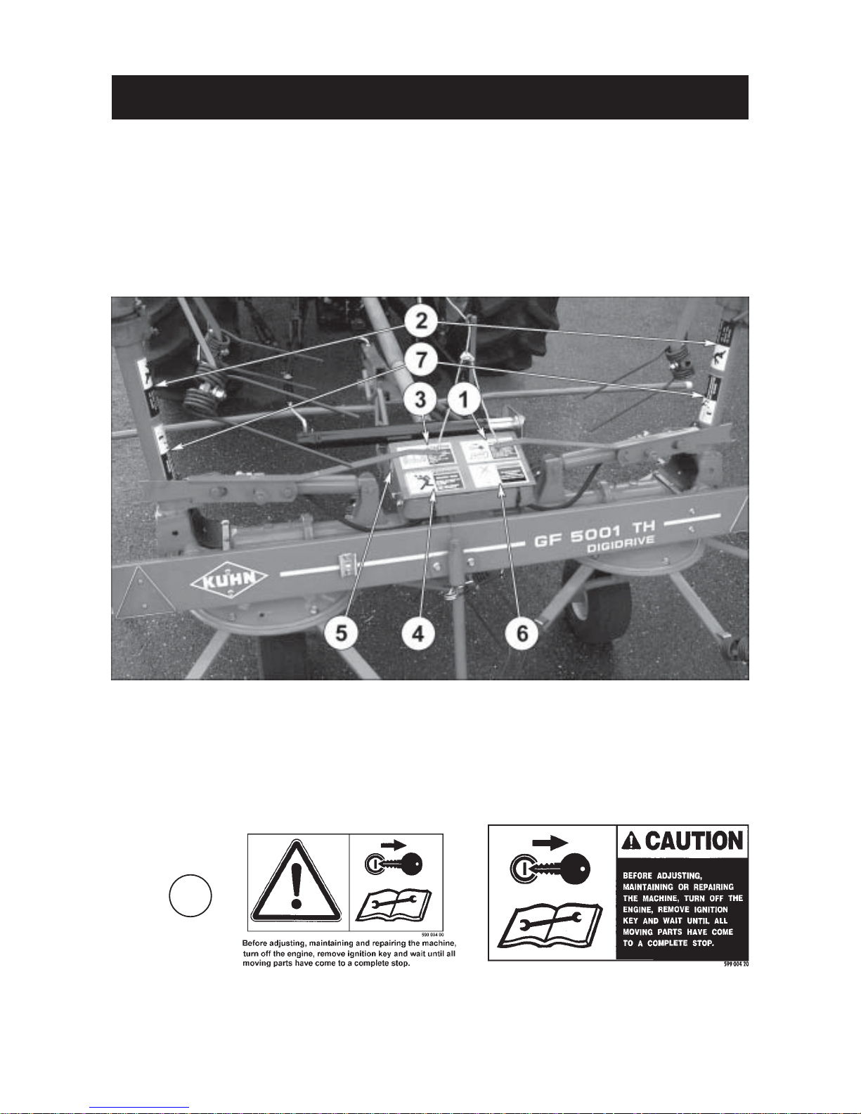
SAFETY DECALS
THE FOLLOWING SAFETY PICTORIALS HAVE BEEN PLACED ON YOUR MACHINE IN THE
AREAS INDICATED. THEY ARE INTENDED FOR YOUR PERSONAL SAFETY AND FOR THE
SAFETY OF THE PEOPLE WORKING WITH YOU. THE TEXT SHOWN ON THEM GIVES THEIR
PRECISE MEANING. ENSURE THAT THESE PICTORIALS ARE ALWAYS LEGIBLE. IF THEY ARE
NOT, REPLACE THEM.
1
Page 12

- 10 -
2
3
4
5
6
7
Page 13

- 11 -
TECHNICAL SPECIFICATIONS
Attachment pull type
Number of rotors 4
Working width (Din. 11220) 5.00 m / 16'5"
Width in work position 5.43 m / 17'9"
Transport width 2.84 m / 9'4"
Length in transport position 2.55 m / 8'4"
Length in working position 2.55 m / 8'4"
Power requirement 15 kW / 20 hp
Weight with PTO 430 kg / 946 lbs
Tyres 15 x 6.00 - 6
Tyre pressure 2 bars / 29 psi
Page 14

- 12 -
ASSEMBLY INSTRUCTIONS
1. Fitting outside rotor casings and hydraulic cylinders (photo 1)
Place outer hinge (B) in the corresponding housing (I) ensuring that couplings are adjusted properly. Fingers
covered by cardboard tubes (J) must be positioned as shown in photo 1.
Insert pivot pins and secure in place using roll pins (K) (dia. 8 x 55 and dia. 5 x 55).
Coat fingers with grease and put flexible guard (N) in place.
Now mount cylinders (P) to central frame tubes (Q) using axles (R) and roll pins (T) (dia. 6 x 36) and fit grease
zerks on pivot pins.
2. Fitting the wheels (photo 2)
Fit the preassembled wheel assemblies (G) on rotor shafts marked with matching numbers and position them
so that the wheel columns (H) are directed towards the front. Secure with roll pins (F) (dia. 12 x 55 and dia.
7 x 55).
ATTENTION : Make sure that the roll pins are fitted 180° to each other and that the slots are facing the direction
of rotor axle (see drawing on photo 2).
3. Fitting the drawbar and crank handle (photo 3)
First fit cover (C) on tongue (U) by means of 4 self-locking screws (D) (M 12 x 30) and 4 self-locking nuts (M 12);
do not tighten.
Fit tongue assembly (U) to the mounting brackets positioned on either side of gearbox (S) using shaft (V) and
2 roll pins (X) (dia 8 x 40). Now tighten the 4 self-locking screws (D). Then connect crank handle (W) to its
mounting bracket (Y) with 1 bushing (O) and 2 roll pins (dia. 6 x 30 and dia. 10 x 30).
4. Fitting the hydraulic hoses (photos 4 and 4 A)
Connect hydraulic hoses (1) to hydraulic cylinders (2) with a banjo, a restrictor bolt and 2 copper washers
(dia 14.5 x 22 x 1.5) as shown. Attach hydraulic hoses (1 and 3) to the tongue (4) with 5 clamp collars (5) (length
350 mm). Fit coupler support (6) to the drawbar with low nut (M18).
5. Fitting control cords (photo 4 A)
Secure holder (7) to drawbar (4) with a hexagonal screw (8) (M8 x 35) and a self-locking nut (M8).
Use the cord (D 1) with a length of 1.4 m (4'7"). Thread it through plate (E). Thread each end of the cord through
lock arm (A) and tie a knot at each end.
Insert the other cord (D 2) with a length of 2.5 m (8'2") through plate (E) and tie a knot.
Thread the other end of cord (D2) through the eyelet of holder (7) and into handle (L). Tie a knot at desired length
so that locks can easily be maneuvered from the tractor seat. Cut off surplus cord at the knot and fit plug (M)
into handle (L).
Page 15

- 13 -
34
4A
Page 16

- 14 -
6. Fitting rear shields and rear parking stand (photos 5 and 6)
Install rear shields (P) on brackets (Q) with 4 self-locking screws (R) (M 8 x 20) and 4 self-locking nuts (M 8).
Then fit the preassembled parking stand (V) and the rear shields (P) on the parking stand bracket with 2 selflocking screws (W) (M 12 x 30) and 2 self-locking nuts (M 12) (photo 6).
Install R-clip (X), then attach PVC cord (Z) on rear shield (P) (photo 6) and squeeze shut the ring.
7. Fitting triangular reflectors (photo 5)
Fit the two triangular reflectors (S) on each side of rear shield (P) using 4 flush screws (T) (M 5 x 35) and 4 selflocking nuts (M 5) (photo 5).
8. Fitting guards (photos 7 and 7 A)
Fit lateral guards (Y) on housings (U) of the outer rotors by means of 2 hexagonal bolts (C) (M 12 x 60) and 2
conical lock washers (M 12) (photo 7).
Install the front guards (A) on the mounting stubs of drawbar (E) with 4 hexagon bolts (H) (M 8 x 45) and 4 selflocking nuts (M 8) as shown in photo 7 A.
Double check that plugs (I and J) are tightly in place (photos 7 and 7 A).
9. Fitting guard cone and its extension (photo 7 A)
Fit the guard extension (L) on the guard cone (M) and bolt this assembly on central gearbox using 2 hexagon
screws (M 10 x 16) and 2 flat washers (dia. 11 x 24 x 2).
10. Fitting tines and tine arms (fig. 8 and 9)
Fit the tine arms as shown in figure 8.
1 = self-locking screw M 12 x 30 2 = self-locking nut M 12
Tighten to a torque of 12 daNm (88 ft.lbs) (see items 1 and 2 on fig. 8)
There are two types of tines :
a) Tines for rotors which turn to the left (counter clockwise) : the KUHN marking is found on the longest finger
(see figure 9).
b) Tines for rotors which turn to the right (clock-wise) : the KUHN marking is found on the shortest finger.
Fit the tines (F) on the tine arms (B) in such a way that the longuest finger is on the ouside and the pressure from
the crop closes the spirals (the tines are facing in the direction of rotation "R" of the rotors) (fig. 9).
Make sure tines (F) are properly positioned into the stamped mark of tine arms (B). Then install deflectors (D),
insert hexagonal screws (A) (M 14 x 50), position washers (C) (dia. 14.5 x 35 x 7 mm) and tighten the self-locking
nuts (E) (M 14) to a torque of 16 daNm (118 ft.lbs) (item A, fig. 9).
During the first hours of work check tine nut and bolt tightness frequently. If necessary, retighten
to 16 daNm (118 ft.lbs) to avoid the possibility of loss or breakage (item A, fig. 9).
Page 17

- 15 -
Page 18

- 16 -
ATTACHMENT
PTO SHAFT
Connect the PTO shaft to the 540 rpm (min-1) tractor drive (with the safety clutch fitted on the machine side).
Make sure PTO length is correct :
1) When the PTO is in its maximum extended position, a minimum tube overlap of 300 mm (12") must be
maintained.
2) When the PTO is in its maximum overlap position (retracted), tubes should not butt against the yokes. As a
safety measure a clearance of at least 2 cm (0.8") must be maintained. If this is not the case, shorten the two
transmission tubes and the two guard tubes by the same length (photos 11 and 12). Bevel and clean the tubes
(photo 13) and grease the inside of the outer tube (photo 14).
3) Never operate the PTO at too great an angle (30° maximum).
These recommendations and adjustments must be respected to avoid damage or premature
wear of the PTO.
Never connect the PTO to the 1000 rpm (min-1) tractor drive.
To avoid accidents which could be serious, make sure that the guards are always correctly
in place and secured with the safety chains. On machine side attach the safety chain around
the drawbar (photo 10 A). Worn or damaged guards must be replaced immediately.
FITTING TO THE TRACTOR
The GF 5001 TH Gyrotedder can be fitted to all types of tractors, preferably those with a pull bar. Attachment
is facilitated when the machine is resting on its front parking stand (A). Adjust the height of the drawbar with the
crank (M) (photo 10).
Following the attachment, raise rear parking stand (R) (photo 10 A), dismount front parking stand (A) from the
drawbar, mount it onto the support (S) provided therefore and secure it in position with pin (E) (photo 10 A).
Connect hydraulic hose (F) to a female hydraulic connection at the rear of the tractor (photo 10).
A ANSI / ASAE 338.4 safety chain (Kit No K8004870) with a minimum ultimate system strength of 45kN
(10,100 lbf) is supplied as standard equipment with all towed machines for North America (USA and Canada).
Use this chain (C) (photo 10B) when towing the rake on a public road. It is intended to keep the machine under
control in the event of a loss or failure of the hitch pin (G) (photo 10B).
Page 19

- 17 -
10
10A
10B
Page 20

- 18 -
WORK POSITION AND ADJUSTMENTS
BEFORE CARRYING OUT ANY OPERATION SUCH AS MAINTENANCE OR ADJUSTMENT ON THE MACHINE, STOP THE TRACTOR ENGINE, REMOVE IGNITION KEY
AND WAIT UNTIL ALL MOVING PARTS COME TO A COMPLETE STOP BEFORE
LEAVING THE TRACTOR.
KEEP ALL PERSONS AWAY FROM THE VICINITY OF THE MACHINE BEFORE PIVOTING
THE OUTER ROTORS INTO WORK POSITION.
To change the machine from the transport position to the work position, proceed as follows :
- Free the outer rotors by releasing locks (L). Turn rotors 180° so that their tines point towards the outside. Make
sure that locks (L) are secured into the work position (photo 15).
- Activate the tractor hydraulics to put hydraulic cylinders (V) under pressure.
- Release locks (R) (photo 15) from the tractor seat by pulling cord (C).
- Lower the outside rotors in working position by releasing pressure (photo 16).
- Use the valve detent to maintain the valve in position "release", or shift the valve into the free floating position
to allow the outer wings to travel up and down with respect to the ground countours.
Perfect rotor angle adjustment using crank handle (M) so that the tines lightly skim the ground at the front
(photo 17).
Page 21

- 19 -
17
15 16
Page 22

- 20 -
OPERATION
The GF 5001 TH must never be operated at a PTO speed (rotational frequency) above 540 rpm (min-1) (figure
18).
With the GF 5001 TH U-turns are made without leaving strips of untedded crop and without losing time
maneuvering (figure 19).
OPERATING SPEED
Many factors govern the choice of the correct forward speed :
1) Moisture content (this factor is most important the first time over).
2) Crop density.
3) Height and type of crop.
Here are a few examples of correct speed given a crop of average length and density :
- First time over : when the crop has a high moisture content, speed is approximately 7 - 8 km/hr (4
1/2 - 5 mph)
- Second time over : speed can reach 10-12 km/hr (6 1/2 - 7 mph) according to the moisture content.
If the hay is dry rotor speed should be reduced. If the crop is very long, heavy and wet, the forward speed should
be reduced. In difficult conditions such as these it is generally advisable to lower the forward speed and
increase the PTO speed. Accurate information cannot be given on this, as speeds must be determined
according to the crops being treated.
Page 23

- 21 -
18
Page 24

- 22 -
TRANSPORT POSITION
KEEP ALL PERSONS AWAY FROM THE VICINITY OF THE MACHINE BEFORE PIVOTING
THE OUTER ROTORS INTO TRANSPORT POSITION.
To fold the machine into its transport position, proceed as follows :
- Disengage PTO shaft.
- Wait for the machine to come to a complete stop.
- Pull cord (N) (photo 21).
- Activate the tractor hydraulics and lift the outer rotors until locks (R) automatically lock into the transport
position (photo 21).
- Free the outer rotors by releasing locks (L) (photo 21). Turn rotors 180° so that their tines point towards the
inside. Make sure that locks (L) are secured into the transport position (photo 21).
- Rotate crank (M) until outer rotors are relatively perpendicular to the ground (photo 22).
- Make sure front parking stand (A) is locked in its horizontal position and that rear parking stand (C) is raised
(photo 22).
NEVER ENGAGE THE PTO SHAFT WHEN THE MACHINE IS IN THE TRANSPORT POSITION.
NEVER TRANSPORT THE GF 5001 TH AT OVER 25 KM/H (15 MPH).
BEFORE TRANSPORTING THE MACHINE ON A PUBLIC ROAD OR HIGHWAY, MAKE SURE
THAT THE MACHINE CONFORMS TO THE HIGHWAY CODE.
PARKING THE MACHINE
The GF 5001 TH is equipped with a front parking stand (A) so that the machine can be parked in its work position
(photo 23).
There is also a rear parking stand (C) so that the machine can be parked in its transport position (photo 24). This
rear stand (C) must be locked in its lowered position with R-clip (E) and the front parking stand (A) must be fitted
in vertical position on the ring at the front of the drawbar and secured with pin (P) (photo 23).
PTO shaft (T) should be positioned in its support (S) to avoid being in contact with the ground (photo 23).
Put male coupling of the hydraulic hose (F) into its parking support (H) (photo 23).
IF THE GF 5001 TH IS TO BE PARKED WHEN IN THE TRANSPORT POSITION, ALWAYS
PARK THE MACHINE ON VERY EVEN, LEVEL GROUND. WEDGES MUST ALWAYS BE
PLACED UNDER THE TWO CENTRAL WHEELS (photo 24).
ENSURE THAT THE SAFETY GUARDS ARE IN REAR POSITION (ROTOR TINES FACING
INWARDS) WHEN PARKING THE MACHINE IN TRANSPORT POSITION.
Page 25

- 23 -
23 24
21
22
Page 26

- 24 -
LUBRICATION
Grease the following points with SHELL RETINAX A :
- Every 100 hours : PTO yoke bearings and drive tubes.
- Every 50 hours :
The four rotors (R) (photo 25), pivot pins (F) and fingers of DIGIDRIVE couplings (I) (photo 26), crank handle
(M) and its pivot point (photo 28) and all other pivoting points of the machine.
- Once a year :
The four rotor gearboxes (G) and pivoting extensions (N) of the outer rotors (photos 26 and 27).
- The drive gearbox is filled with SHELL RETINAX A grease (capacity : 0.800 kg). Check the amount once a
year by removing the rear cover.
Lubricate the following point s with SHELL X 100 or SAE 90 EP OIL :
- Once a week : the axles (A) of the hydraulic cylinders (photo 28).
TO ENSURE TROUBLE FREE OPERATION OF YOUR MACHINE,
WE RECOMMEND THE USE OF SHELL LUBRICANTS
Page 27

- 25 -
Page 28

- 26 -
OPTIONAL EQUIPMENT
1) DUPLEX REDUCTION GEARBOX (Kit No 111 6440)
A «Duplex» reduction gearbox for the GF 5001 TH can be supplied as an optional extra when using the machine
for raking night swaths. With this gearbox, the high rotor speed necessary for tedding and turning is maintained
and there is also a lower rotor speed for raking night swaths.
The reduction gearbox can be attached to existing GF 5001 THs without modification. To install the «Duplex»
reduction gearbox proceed as follows :
- Fit guard (G) (photo 30) on Duplex reduction gearbox, using the hardware provided.
- Remove original PTO shaft guard from the central gearbox.
- Slide the Duplex reduction gearbox unit (Q) on the drive shaft from the central gearbox (R) and secure in place
with 2 self-locking screws (S) (M 12 x 40) and 2 conical spring washers (photo 29) (torque : 9 daNm - 65 ft.lbs).
The spacer washer delivered with the kit has to be fitted on the lower screw (S) between bracket ( K) and central
gearbox (R) (photo 29).
- Fit the retaining ring (35 E) delivered with the kit on the central gearbox drive shaft.
When tedding, the PTO shaft must be fitted directly to the splined end of drive shaft. When raking night swaths,
mount the PTO shaft on the «Duplex» reduction gearbox input shaft (photo 30). In this case the tractor PTO speed
(rotational frequency) should be maintained at 400 rpm (min
-1
) and ground speed between 5-7 km/h (3-4 miles/
h). Mount the PTO shaft cover (E) inside the guard (G) using wing nut (H) so that the PTO stub not in use is fully
guarded (photo 30).
Page 29

- 27 -
30
Page 30

- 28 -
SOUND LEVELS
Sound levels given out by : GF 5001 TH Gyrotedder
Sound levels have been measured in accordance with the measuring methods as defined in :
HM Agricultural Inspectorate
AGRICULTURAL MACHINERY NOISE
Legislation and guidance on methods of testing
(Annex to AIC 1896/117 REV)
February 1988
Health and Safety Executive
The method employed corresponds to the method No. 4 in this document. Unspecified testing
conditions comply with ISO 5131 standard.
Measuring equipment conforms to NF S 31-009 standard. The tractor used has a power of 59 kW.
A-weighted emission sound pressure level L (A) eq inside tractor cab (with closed windows) :
Tractor only : 78.7 dB (A)
Tractor + machine : 77.7 db (A)
Page 31

LIMITED WARRANTY
KUHN S.A. of 4 Impasse des Fabriques, 67706 SAVERNE CEDEX, France (hereinafter called the
«Company») warrants, in accordance with the provisions below, to each original retail purchaser of
KUHN new equipment of its own manufacture, from an authorized KUHN dealer, that such equipment
is, at the time of delivery to such purchaser, free from defects in material and workmanship and that
such equipment will be warranted for a period of one year starting from the date the goods are delivered
to the end user and during this period up to a limit of 500 hours use, providing the machine is used and
serviced in accordance with the recommendations in the Operators Manual.
THESE CONDITIONS ARE SUBJECT TO THE FOLLOWING EXCEPTIONS :
1. Parts of machines which are not of our manufacture i.e. tyres, belts, P.T.O. shafts, clutches etc., are not
covered by this Limited Warranty but are subject to the warranty of the original manufacturer. Any claim
falling into this category will be taken up with the manufacturer concerned.
2. Warranty claims applying to these types of parts must be handled in the same way as if they were parts
manufactured by KUHN. However, compensation will be paid in accordance with the warranty agreement of the manufacturer concerned in as much as the latter justifies such a claim.
3. This Limited Warranty will be withdrawn if any equipment has been used for purposes other than for
which it was intended or if it has been misused, neglected or damaged by accident or let out on hire. Nor
can claims be accepted if parts other than those manufactured by us have been incorporated in any of
our equipment. Furthermore, the Company shall not be responsible for damage in transit or handling by
any common carrier and under no circumstances within or without the warranty period will the Company
be liable for damages for loss of use or damages resulting from delay or any consequential damage.
We cannot be held responsible for loss of earnings caused by a breakdown or for injuries either to the owner
or to a third party, nor can we be called upon to be responsible for labor charges, other than originally
agreed, incurred in the removal or replacements of components.
THE CUSTOMER WILL BE RESPONSIBLE FOR AND BEAR THE COSTS OF:
1. Normal maintenance such as greasing, maintenance of oil levels, minor adjustments, etc.
2. Transportation of any kind of any KUHN product to and from the place the warranty work is performed.
3. Dealer travel time to and from the machine or to deliver and return the machine from the workshop for
repair.
4. Dealer travelling costs.
Parts defined as normal wearing items are listed as follows and are not in any way covered under this
Limited Warranty :
V belts, discs, knives, wear plates, disc guards, tires, torque limiters, hydraulic hoses, pitman shafts, swath
sticks, blades, tines and tine holders.
KUHN Limited Warranty will not apply to any product which is altered or modified without the expressed
permission of the Company and/or repaired by anyone other than Authorized Service Distributors or
Authorized Service Dealers.
Page 32

LIMITED WARRANTY IS DEPENDENT UPON THE STRICT OBSERVANCE BY THE
PURCHASER OF THE FOLLOWING PROVISIONS :
- That this Limited Warranty shall not be assigned or transferred to anyone unless the Companys consent in
writing has first been obtained.
- The warranty/product registration form has been correctly completed by dealer and purchaser with their
names and addresses, dated, signed and returned to the appropriate address as given on the warranty/
product registration form.
- The claim form sent to KUHN has been correctly completed stating:
* dealers name and address
* owners name and address
* type of machine
* machine serial number
* delivery date to buyer
* date of failure
* tractor make and type
* description of the failure and its cause
* quantity, reference number and name of the damaged parts
* reference number, quantity and date of the invoice for the replacement parts.
- The judgement of the Company in all cases of claims under this Limited Warranty shall be final and conclusive and the purchaser agrees to accept its decisions on all questions as to defect and to the exchange of
any part or parts.
- That all safety instructions in the Operators Manual shall be followed and all safety guards regularly inspected
and replaced where necessary.
No warranty is given on second-hand products and none is to be implied. Persons dealing in the Companys
products are in no way legal agents of the Company and have no right or authority to assume any obligation
on their behalf, express implied, or to bind them in any way.
KUHN S.A. reserves the right to incorporate any change in design in its products without obligation to make
such changes on units previously manufactured.
Moreover, because of the constant progress in technology, no guarantee is given to the descriptions of
equipment published in any document by the company.
DISCLAIMER OF FURTHER WARRANTY
There are no warranties, expressed or implied, except as set forth above. There is no
warranty of merchantability. There are no warranties which extend beyond the description
of the product contained herein. In no event shall the company be liable for indirect, special
or consequential damages (such as loss of anticipated profits) in connection with the retail
purchasers use of the product.
Page 33

- N O T E S -
Page 34

Page 35

This machine complies with the safety requirements of the European machinery directive.
The Operator should respect all Health and Safety regulations as well as the Highway
Code. For your own safety, use only genuine KUHN spare parts. The manufacturer
disclaims all responsibilities due to incorrect use or non-compliance with the
recommendations given in this manual.
Page 36

Printed in France by KUHN
KUHN S.A. 4 Impasse des Fabriques F - 67706 SAVERNE CEDEX (FRANCE)
Tél. : + 33 (0) 3 88 01 81 00 - Fax : + 33 (0) 3 88 01 81 03
www.kuhnsa.com - E-mail : info@kuhnsa.com
Société Anonyme au Capital de 19 488 000 Euros
For your safety
and to get the best from your machine,
use only genuine KUHN parts
 Loading...