

Page 1

OPERATOR'S MANUAL
KN072CGB B
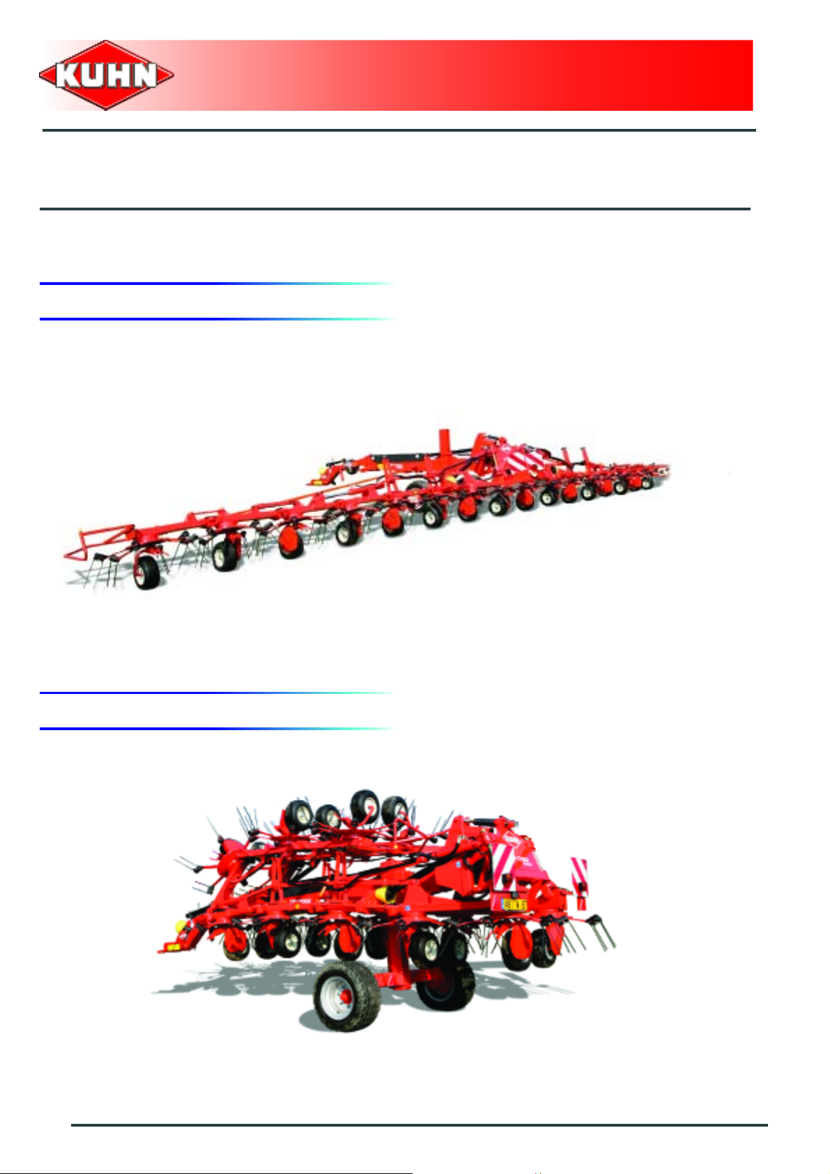
Gyrotedder
GF17002
KN072CGB B
- English - 12-2009
Page 2

Page 3

Gyrotedder
GF17002
$Dear Owner
In buying a Kuhn machine you have chosen wisely. Into it have gone years of thought, research and
improvement. You will find, as have thousands of owners all over the world, that you have the best that
engineering skill and actual field testing can produce. You have purchased a dependable machine, but only
through proper care and operation can you expect to receive the performance and long service built into it.
This manual contains all the necessary information for you to receive full efficiency from your machine. The
performance you get from this machine is largely dependent on how well you read and understand th is manual
and apply this knowledge. Please DO NOT ASSUME YOU KNOW HOW TO OPERATE AND MAINTAIN YOUR
MACHINE before reading this manual carefully. KEEP THIS MANUAL AVAILABLE FOR REFERENCE. Pass
it on to the next owner if you re-sell the machine.
Your KUHN dealer can offer a complete line of genuine KUHN service parts. These parts ar e manufactured and
carefully inspected in the same factory that builds the machine to assure high quality and accurate fitting of any
necessary replacements.
About improvements
We are continually striving to improve our products. It therefore reserves the right to make improvements or
changes when it becomes practical to do so, without incurring any obligations to make changes or additions to
the equipment sold previously.
Designated use of the machine
The GF17002 gyrotedder must only be used for the purpose for which it was manufactured: spreading and
tedding previously cut forage or straw.
Dear Owner
1
Page 4

Gyrotedder
GF17002
$Contents
Dear Owner.....................................................................................................................1
Contents .........................................................................................................................2
Identification of the machine.........................................................................................4
Rear view (working position)...........................................................................................................4
Rear view (transport position).........................................................................................................4
Model identification plate ................................................................................................................5
Safety...............................................................................................................................6
Description of symbols used in this document.............................................................................6
Safety instructions...........................................................................................................................7
Location and description of safety decals on the machine .......................................................15
Road safety equipment and recommendations...........................................................................18
Machine specifications................................................................................................20
Description and glossary...............................................................................................................20
Technical specifications...................... .... ... ... ....................................................... ... ... .... ... ............21
Sound levels ......... ... ... .... ... ... ... .... ................................................... .... ... ... ... ... .... ... .........................23
Putting into service......................................................................................................24
Description of control elements....................................................................................................24
Coupling and uncoupling..............................................................................................................25
Instructions for transport............................................................................................36
2
Putting the machine into transport position................................................................................36
Conformity with the road regulations...........................................................................................38
Contents
Page 5

Gyrotedder
GF17002
Instructions for work...................................................................................................39
Putting the machine into work position.......................................................................................39
Adjustments in working position..................................................................................................41
Machine use....................................................................................................................................43
Optional equipment.....................................................................................................45
Intermediate PTO transmission shaft with constant velocity joint ...........................................45
Deflector..........................................................................................................................................46
Ball hitch drawbar diameter 80 mm (3.1’’) ...................................................................................47
Maintenance and storage............................................................................................ 51
Frequency chart .............................................................................................................................51
Lubrication............................................................................................ ..........................................52
Maintenance....................................................................................................................................59
Storage............................................................................................................................................63
Limited warranty..........................................................................................................64
Contents
3
Page 6
$Identification of the machine
1. Rear view (working position)
Gyrotedder
GF17002
2. Rear view (transport position)
4
Identification of the machine
Page 7
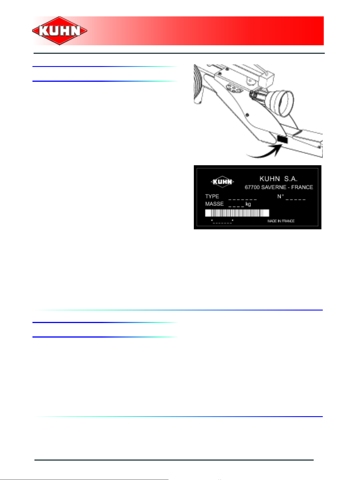
3. Model identification plate
Please write below the type and serial number of the
machine. This information is to be indicated to the dealer
for all spare parts orders.
Gyrotedder
GF17002
Type: GF17002
Serial no.:
4. Optional equipment
Tick box corresponding to the equipment fitted on your
machine:
Kit no. 4800405: Primary PTO transmission shaft with constant velocity joint
(1"3/8 - 21 spline pto shaft).
Kit no. 1126500: Border curtain.
Kit no. 1126470: Ball hitch drawbar diameter 80 mm (3.1’’).
Identification of the machine
5
Page 8
$Safety
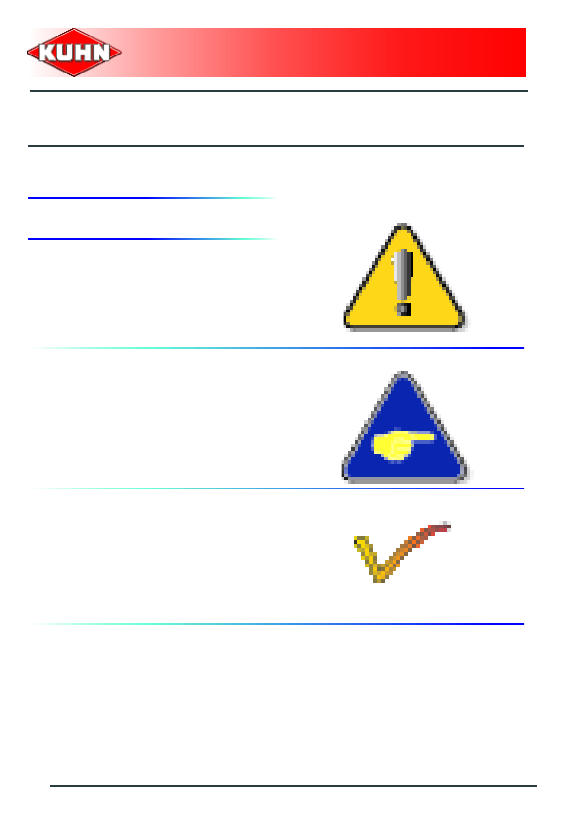
1. Description of symbols used in this document
This symbol indicates a potentially hazardous situation
that if not avoided, could result in serious bodily injury.
Gyrotedder
GF17002
This symbol is used to identify special instructions or
procedures which, if not followed strictly, could result in
machinery damage.
This symbol is used to communicate technical
information of particular interest.
6
Safety
Page 9
Gyrotedder
GF17002
2. Safety instructions
Introduction
The machine must only be operated, maintained and repaired by competent persons who are familiar with
machines' specifications and operation and aware of safety regulations fo r preventing accidents.
The operator must imperatively respect safety instructions in this manual and in the warnings posted on the
machine. The operator is also obliged to respect current le gislation concerning accident prevention, wo rk safety
and public traffic circulation.
Designated use of the machine also means following operation, maintenance and repair recommendations
given by the manufacturer, and using only genuine spare parts, equipment a nd acce sso ries, as r ecom mended
by the manufacturer.
The manufacturer is not held liable for any damage resulting from machine applications other than those
specified by the manufacturer. Any use other than the designated operation is at the risk and responsibility of
the operator.
The manufacturer is not held liable for any damage or accident re sulting from machine modifications carried out
by the operator himself or by a third party without previous written agreement from the manufacturer.
Read and follow the safety instructions
Before using the machine, carefully read all the safety
instructions in this manual and the warnings placed on
the machine.
Before starting work, the operator must be familiar with
all machine controls, handling devices and their
functions. It is too late to learn once work has been
started!.
Never let anyone operate the machine who is not traine d
to do so.
Should you have any difficulties in understanding certain
parts in this manual, please contact your KUHN dealer.
Precautions to be taken before carrying out
any operations on the machine
Before leaving the tractor or before adjusting,
maintaining or repairing the machine, disengage the
PTO drive, turn off the engine, remove ignition key and
wait until all moving parts have come to a complete stop
and apply park brake.
Safety
7
Page 10
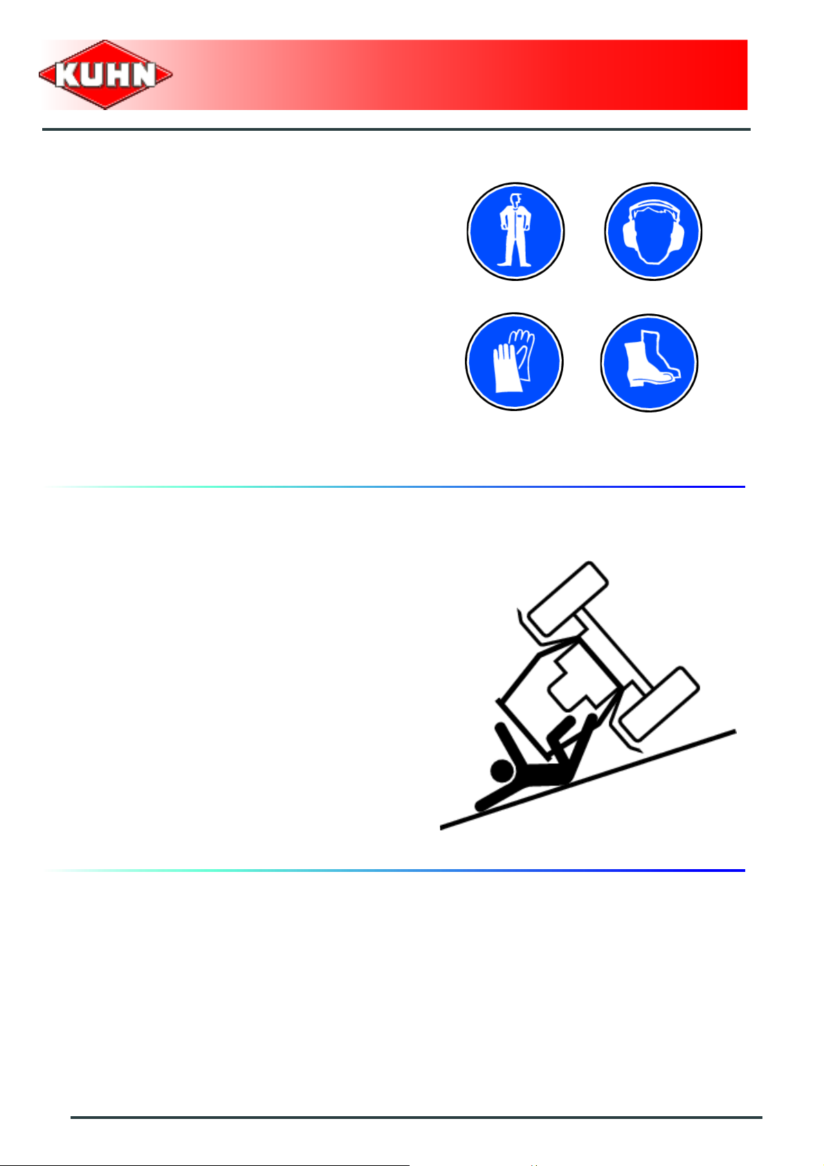
Precautions to take before using the
machine
Do not wear loose clothing which could become caught
up in moving parts.
Wear the appropriate protective clothing for the work in
hand (gloves, shoes, goggles, helmet, ear defenders,
etc.).
Ensure that all operating controls (ropes, cables, rods,
etc) are placed so as they cannot be operated
unintentionally and cause damage or injury.
Before operating the machine, check tightness of nuts
and bolts, particularly on fixing elements (tines, forks,
blades, knives, etc). Retighten if necessary.
Before operating the machine, ensure that all the safety
guards are firmly in place and in good condition.
Immediately replace any worn or damaged guard.
Gyrotedder
GF17002
Precautions when driving
Tractor handling, stability, performance and braking
efficiency are all affected by weight distribution, trailed or
mounted implements, additional ballast and driving
conditions. It is therefore of great importance that the
operator exercises caution in every given situation.
Groundspeed must be adapted to ground conditions as
well as to roads and paths. Always avoid abrupt change s
of direction.
Be particularly cautious when turning corners, paying
attention to machine overhang, length, height and
weight.
Never use a narrow track tractor on very uneven or
steeply sloping ground.
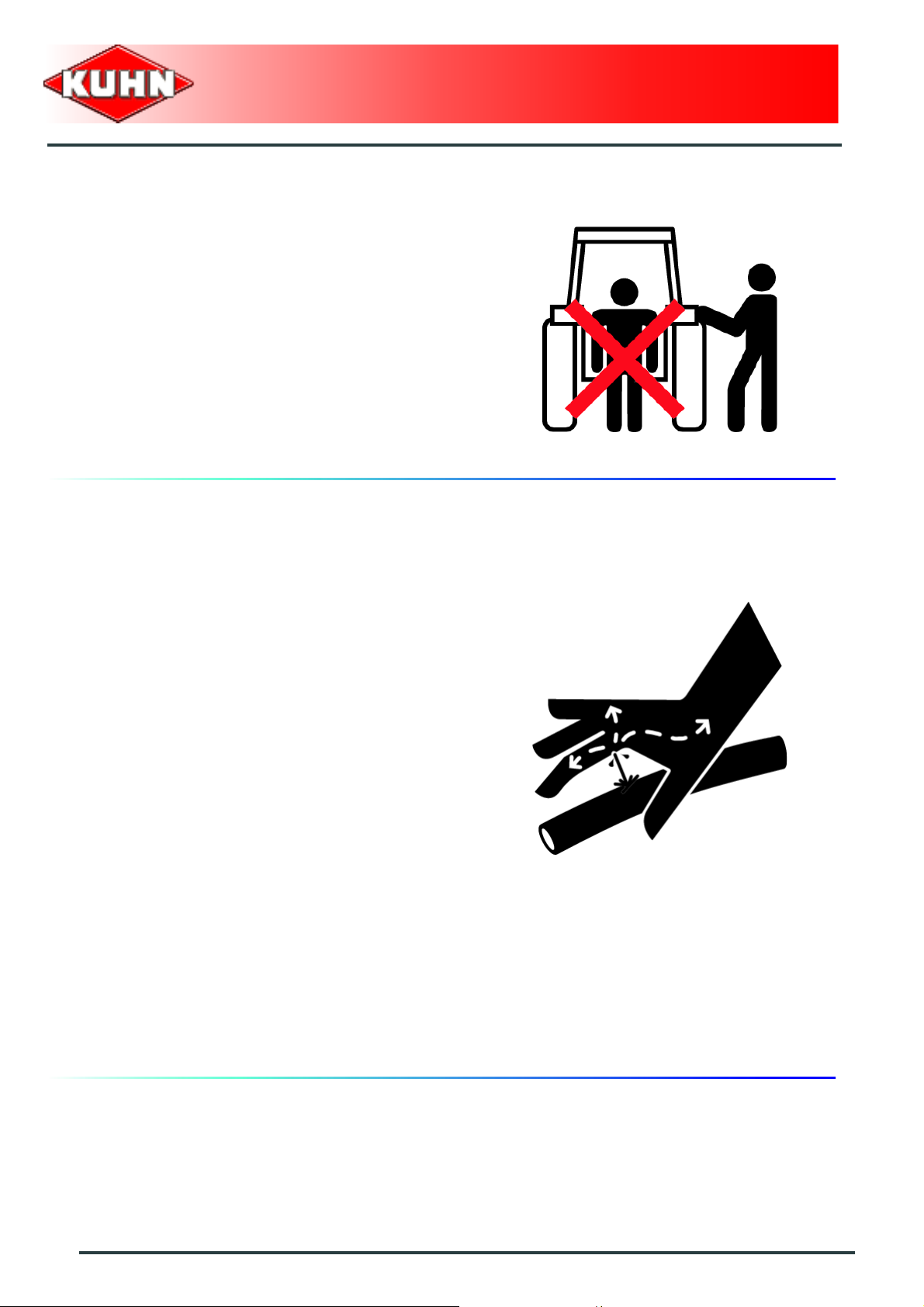
Never leave the tractor seat while the machine is
operating.
Carrying people or animals on the machine when
working or in transport is strictly forbidden.
8
Safety
Page 11
Precautions when driving on public roads
Dimensions
Depending on the dimensions of the machine, contact
the relevant authorities to ensure that it can be legally
transported on public roads.
If the machine is over the maximum legal size, follow the
local regulations for special transportation of oversize
equipment.
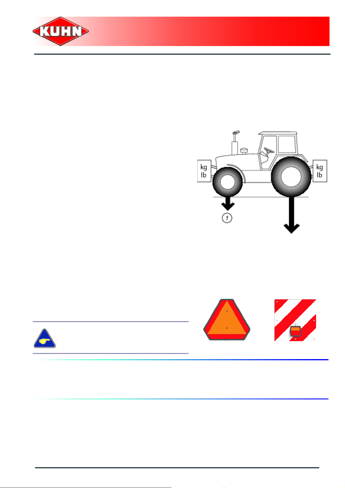
Gross weight and weight per axle
Check that the tractor's authorized gross weigh t as well
as its lift capacity and maximum weight per axle are not
exceeded.
The front axle load (1) must never, under any
circumstances, be less than 20% of the tractor's unladen
weight. If necessary, add ballast weights to the front or
to the rear to preserve the steering and braking
efficiency.
Gyrotedder
GF17002
Transport position
Before transporting the machine on public roads, place
the machine into its transport position, according to the
instructions in this manual.
Lights and indicators.
Before transporting the machine on public road s, ensure
that all legally required lightings and signallings are in
place.
Ensure that lightings and signallings are clean and in
good working order. Replace any missing or broken
equipment.
Always obey current regulations for driving
on roads
Maximum speed
Always keep to the legal speed limit for driving a tractormachine assembly on public roads.
Safety
9
Page 12
Precautions when coupling
Before attaching the machine, make sure that it cannot
accidentally start moving (chock the wheels) and that the
parking stand is in the right position.
The machine must only be attached to the hitch points
provided for this purpose.
Never stand between the tractor and the machine when
operating the three point linkage.
Do not stand between the tractor and the machine
without ensuring that the parking brake is applied.
Hydraulic circuit
Gyrotedder
GF17002
Caution! The hydraulic circuit is under high pressure.
Maximum pressure at work: 200 bar.
Before connecting hoses to the tractor hydraulics,
ensure that tractor and machine circuits are not under
pressure.Before disconnecting a hose, depressurize the
hydraulic circuit.
To avoid making incorrect connections, mark hydraulic
couplers and corresponding hoses with colors.
WARNING! Functions could be reversed (for example:
lift/lower) and cause accidents.
Regularly check the hydraulic hoses. In case of normal
wear, replace the hydraulic hoses every 5 years.
Damaged or worn hoses must immediately be replaced.
When replacing the hydraulic hoses, only use hoses with
the specification recommended by the manufacturer of
the machine.
To locate a leak, use appropr iate means. Protect body
and hands from liquid under pressure.
Any liquid under pressure (particularly oil from
hydraulics) can penetrate the skin and cause severe
injury. If injured, see a doctor immediately, there could
be danger of infection.
Before any adjustments, maintenance or repairs are
carried out, lower the machine to the ground,
depressurize the hydraulics, turn off the engine, remove
ignition key and wait until all moving parts have come to
a complete stop.
10
Safety
Page 13

PTO shaft
Use only PTO shafts supplied with the machine or
recommended by the manufacturer.
The protective shield of the tractor PTO stub, the PTO
shaft guards and the protective covering of the machine
input shaft must always be in place and in good
condition.
Make sure that the PTO shaft guards are se cured with
the safety chains provided.
Any worn or damaged guards must be replaced
immediately.A worn guard or an u nprotected PTO shaft
can cause a serious or even a lethal accident.
Do not wear loose clothing that could be caught in the
rotating PTO shaft.
Before attaching or removing a PTO shaft, or before
doing any work on the machine, disengage the PTO
drive, turn off the engine, remove ignition key and wait
for all moving parts have come to a complete stop.
If the primary PTO shaft is equipped with a slip clutch or
a free wheel, these must be fitted on the machine side.
Ensure that the PTO shaft is always correctly fitted and
locked into place.
Before connecting the PTO shaft, ensure that the PTO
speed (rotational frequency) and directions of rotation
are in line with manufacturer's recommendations.
Before engaging the PTO drive, make sure all people
and animals are clear from the machine. Never engage
the PTO drive when the tractor engine is stopped.
When uncoupling the machine, rest the PTO shaft on the
support specially provided, and replace protective cover
on the PTO stub of the tractor.
Read and follow the instructions in the operator's ma nual
provided with the PTO shaft.
Gyrotedder
GF17002
Safety
11
Page 14
Precautions during manoeuvres
When moving the machine from the transport positio n to
the working position and vice versa, make sure that
nobody is within the machine pivoting area.
Remote controlled components
Danger of crushing and shearing can exist when
components are operated by hydraulic or pneumatic
controls. Keep away from these danger zones.
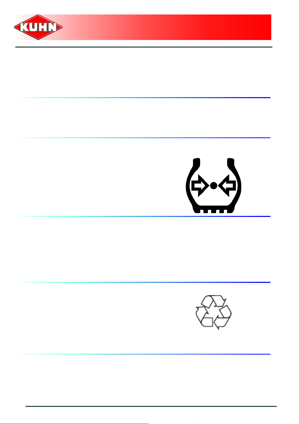
Tyres
Regularly check the tyre pressure. Respect
manufacturers' recommendations on pressure.
Assembly, disassembly and repair of wheels and tyres
must only be carried out by competent persons who are
equipped with standardized tools. Before any work is
performed on the wheels, ensure that the machine rests
on the ground and is perfectly stable so that it cannot
move accidentally (put chocks in place).
Gyrotedder
GF17002
Safety decals
Safety warning decals are placed in pictorial form on
various parts of the machine. They are ther e to warn you
of potential dangers and to tell you how to avoid
accidents.
Always keep the safety decals clea n and readable, and
replace them when they are worn, damaged, missing or
illegible.
Waste disposal
Respect the environment! Never spill pollutants (oil,
grease, filters, etc.) on the ground, never pour them
down the drain and never discard them in any other
place where they could pollute the environment. Never
throw away or burn a tyre. Always take waste to
specialized recycling or waste disposal centers.
12
Safety
Page 15

Precautions for maintenance and repair
work
Before leaving the tractor or before adjusting,
maintaining or repairing the machine, disengage the
PTO drive, turn off the engine, remove ignition key and
wait until all moving parts have come to a complete stop
and apply park brake.
Rest the machine on the ground, release the pressure
from the hydraulic circuit and leave the machine to cool
down.
Make sure that the parts of the machine that need to be
lifted for maintenance or repair work are firmly propped
up.
Before any work is done on the electric circuit or before
any electric welding is carried out on the attached
machine, disconnect the machine from the tractor
electrical circuit. Also disconnect alternator and battery
terminals.
Repairs on elements under pressure or tension (springs,
pressure accumulators, etc.) must only be carried out by
competent persons with regulation equipment.
Wear the appropriate protective clothing for the work in
hand (gloves, shoes, goggles, helmet, ear defenders,
etc.).
Do not solder, weld or use a blow torch near fluids under
pressure or inflammable products.
For your own safety and for correct machine operation,
only use original manufacturer parts.
It is strongly recommended to have your machine
checked by your Kuhn dealer after each season,
especially tools and their attaching hardware (nuts,
bolts, etc.).
Gyrotedder
GF17002
Projection of stones and foreign objects
For driver safety, always use a tractor equipped with a
cab. Never start the machine when there are people
nearby.
Even when the machine is used in accordance with its
purpose, objects may be projected. Stones and other
foreign objects projected by the movin g parts can tr avel
a considerable distance. Keep all persons and animals
away from the danger zone.
Safety
13
Page 16

Precautions for machine use
Before using the machine, check tools ( tines) and their
attachment hardware in accordance with the instructions
of the present manual.
Check the guards regularly. Immediately replace any
damaged or missing elements.
Before engaging the pto drive, lower the rotors onto the
ground. Make sure all the guards are in place. Keep all
persons and animals away from the danger zone.
Keep a safe distance from the Gyrotedder when the
rotors are in movement.
Never work in reverse.
After the power source has stopped, the rotors can
continue turning for a time. Stay away from the machine
until all moving parts have come to a complete standstill.
If an obstacle is hit, disengage the PTO drive, stop the
tractor engine, remove the ignition key and wait for all
moving parts to come to a complete standstill. Check the
entire machine for any damage before resuming work.
Gyrotedder
GF17002
14
Safety
Page 17
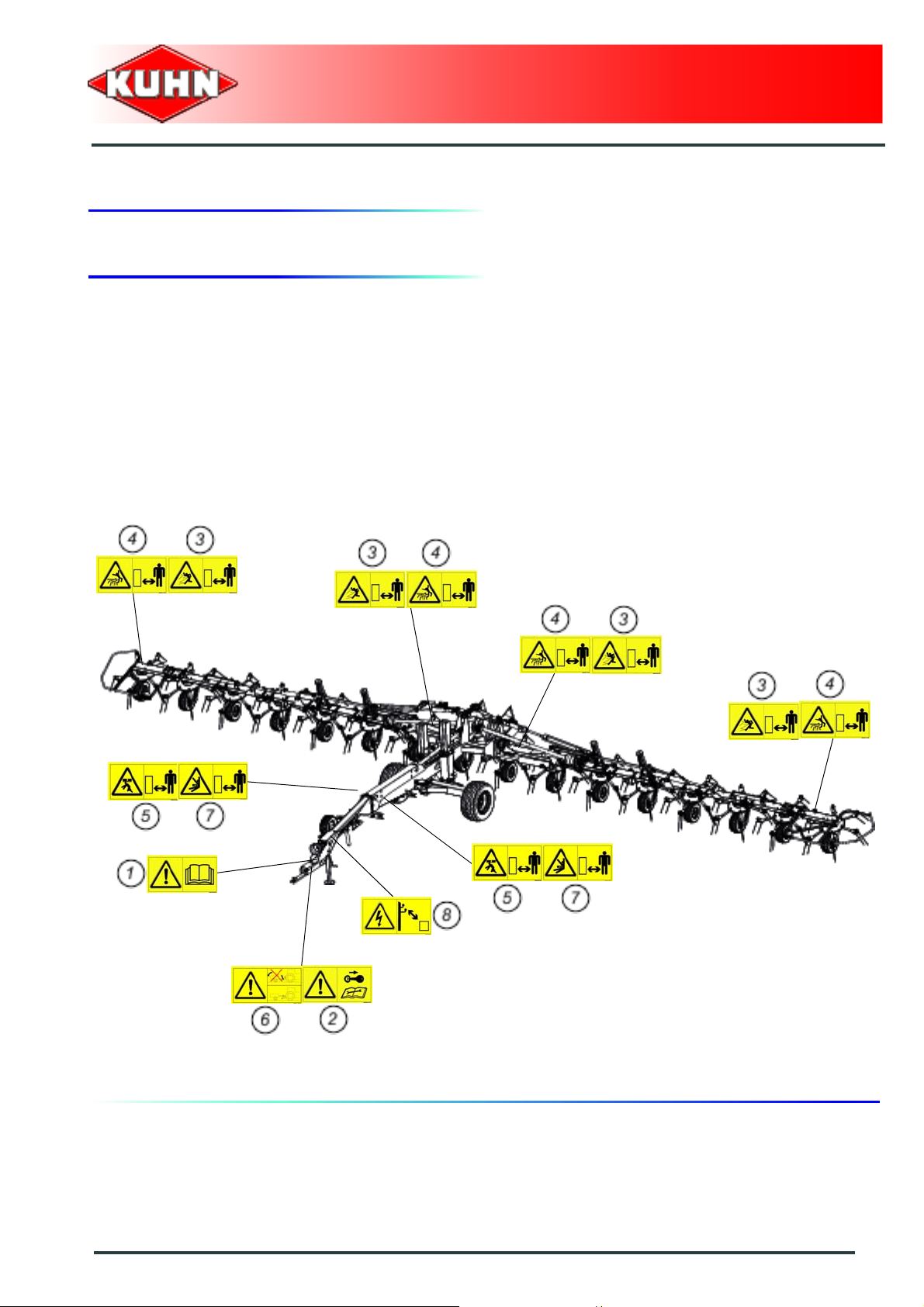
3. Location and description of safety decals on the machine
Location of safety decals
Gyrotedder
GF17002
Safety
15
Page 18
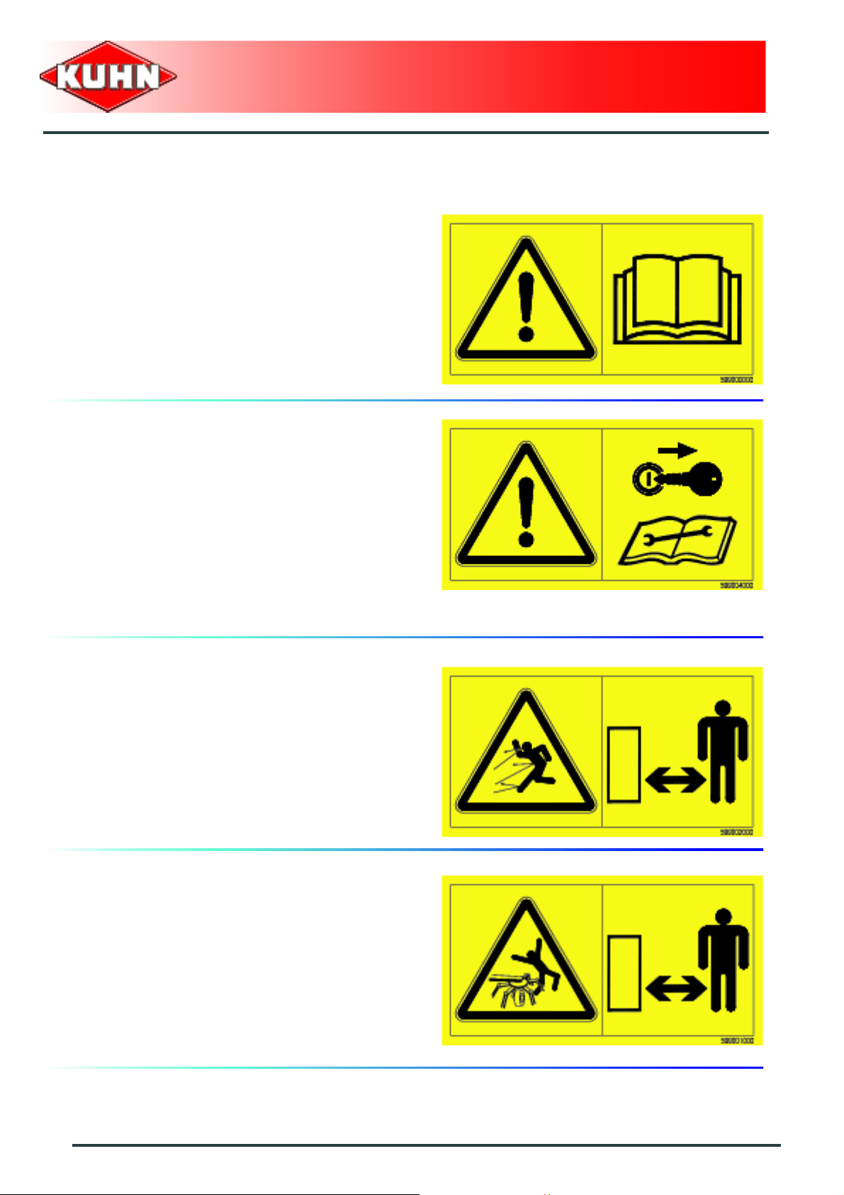
Description of safety decals
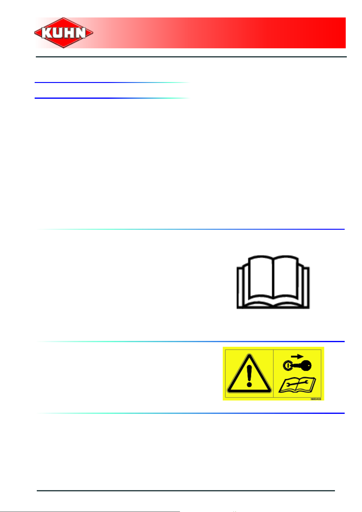
Operating instructions (1)
The operators' manual contains all the information
necessary for using the machine safely. It is imperative
to read and comply with all instructions.
Working on the machine (2)
Before leaving the tractor or before adjusting,
maintaining or repairing the machine, disengage the
PTO drive, turn off the engine, remove ignition key and
wait until all moving parts have come to a complete stop
and apply park brake.
Gyrotedder
GF17002
Projections (3)
Stones and other debris pro jected by the moving parts
can travel a long distance. Always stay at a safe distance
from the machine.
Rotary tools (4)
To prevent entanglement keep a safe distance from the
machine.
16
Safety
Page 19
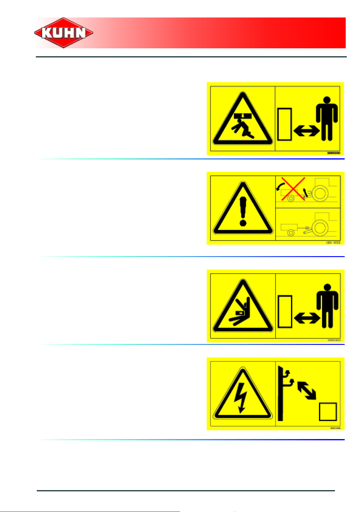
Body crushing (5)
Stay a safe distance from the machine. Crushing hazard.
Coupling device (6)
Never couple the machine to the multihole bar, there is a
risk of tipping over. Couple the machine to the pull bar or
eye bolt.
Gyrotedder
GF17002
Manoeuvring area (7)
Stay a safe distance from the machine. Crushing hazard.
Electric lines (8)
Before any machine unfolding/folding operation, check
that the electric lines are distant enough. There is a risk
of an electric shock and electrocution..
Safety
17
Page 20
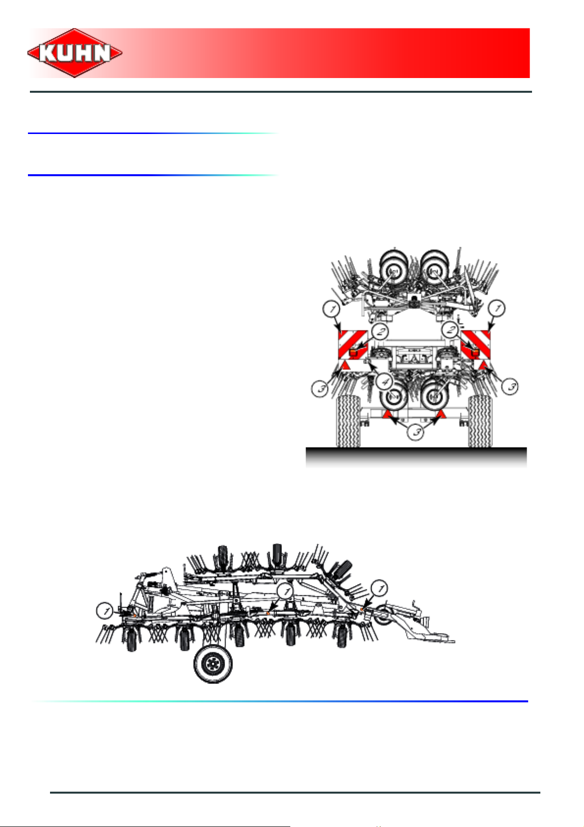
4. Road safety equipment and recommendations
The road safety equipment is mounted in the factory or
by your authorized Kuhn dealer according to current
safety regulations. Always keep to the legal speed limit
for driving a tractor-machine assembly on public roads.
Whatever the speed, we recommend, for everyones'
safety, not to exceed a maximum speed of 40 km/h
(25 mph).
The rear safety device comprises:
- 2 signalling panels (1)
(The reflective panels are double sided).
- 2 signalling lights (2)
(red light / stop light / turn signal light).
- 4 red reflectors (3).
- 1 identification plate light (4).
Gyrotedder
GF17002
The side device comprises:
- 3 amber reflectors (1) on each machine side.
18
Safety
Page 21
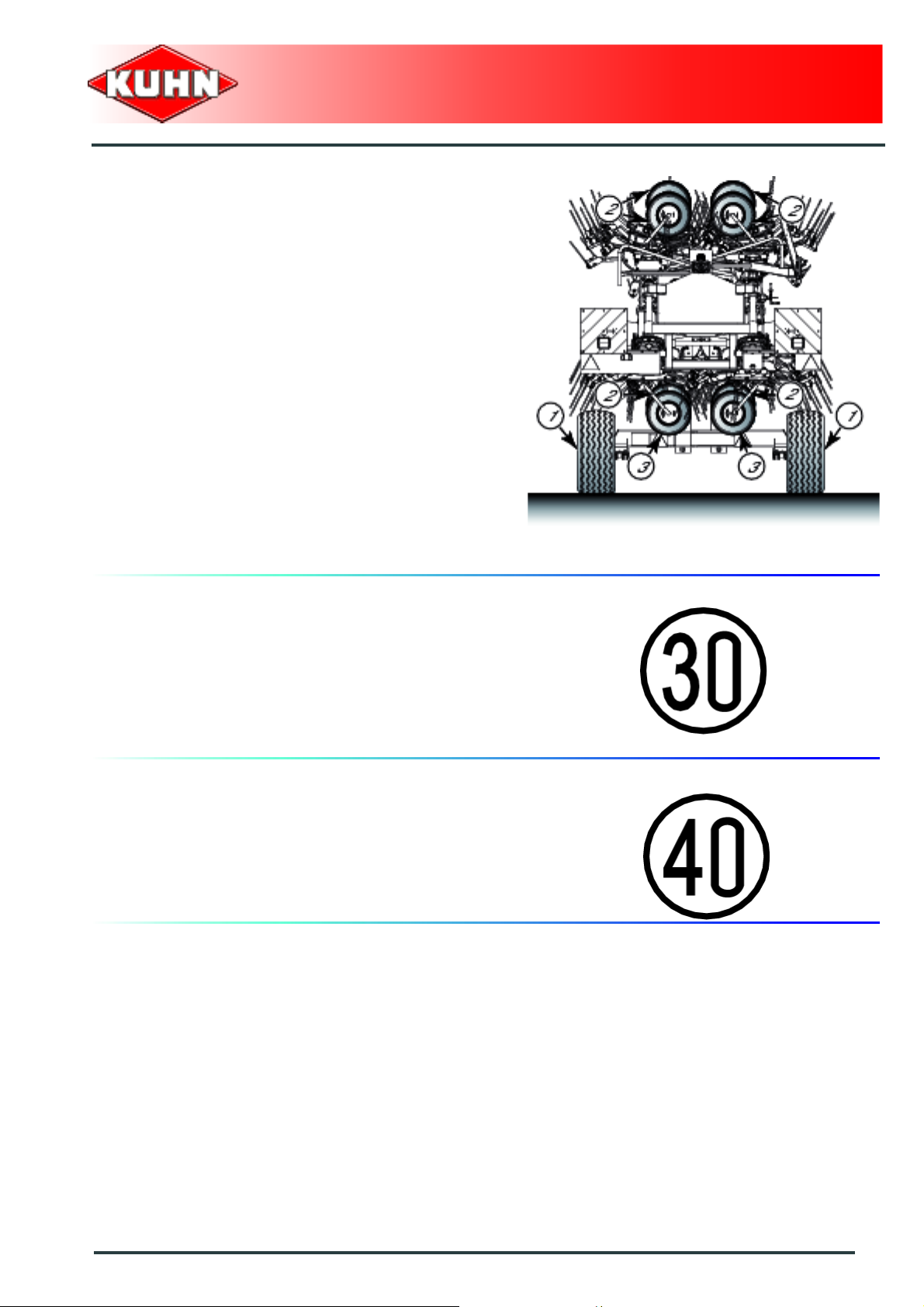
Tyre pressure
- Transport wheels (1): 2.5 bar (37 psi).
- Wheels (Central rotors) (3): 2.0 ba r (2 9 psi).
- Rotor wheels (2): 1.5 bar (22 psi).
Gyrotedder
GF17002
Specific requirements for Germany
Speed
Always keep to the legal speed limit of
30 km/h (18.6 mph) for driving a tractor-machine
assembly on public roads.
Instructions specific to France
Speed
Always keep to the legal speed limit of 40 km/h (25 mph)
for driving a tractor-machine assembly on public roads.
Safety
19
Page 22
$Machine specifications
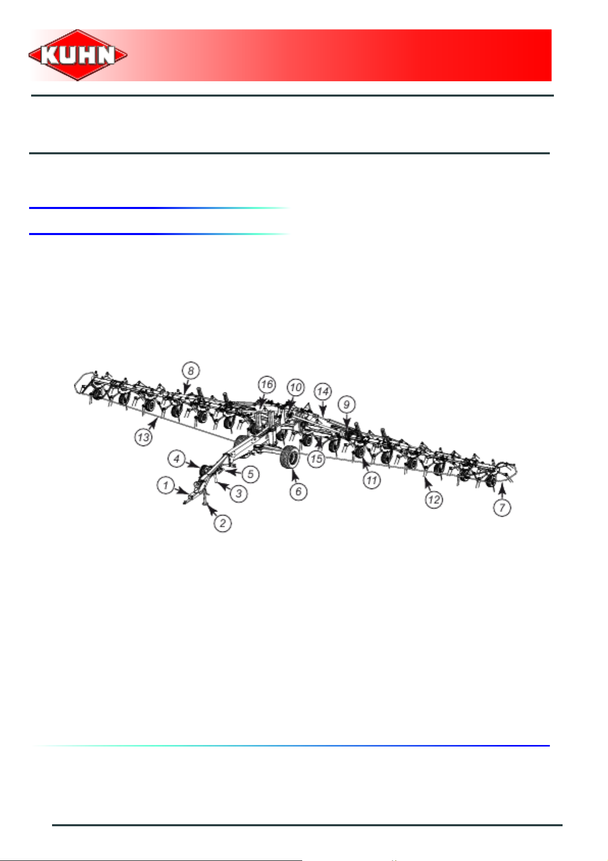
1. Description and glossary
0
Gyrotedder
GF17002
1 : Drawbar 2 : Parking stand
3 : Pitch angle adjustment handle 4 : Spare wheel
5 : Wheel chocks 6 : Transport wheel
7 : Outer guard 8 : Outer wing folding cylinder
9 : Side gearbox 10 : Central gearbox
11 : Rotor wheels 12 : Tine
13 : Central guard (Strap) 14 : Lift cylinder
15 : Folding cylinder 16 : Rotor positioning cylinder
20
Machine specifications
Page 23

2. Technical specifications
Gyrotedder
GF17002
GF17002
Attachment type
Number of rotors 16
Number of tine arms per rotor 6
Working width (DIN11220) 17.20 m (56’5’’)
Width in working position 17.70 m (58’)
Length in working position 7.50 m (24’07’’)
Height in working position 1.85 m (6’)
Width in transport position 2.40 m (7’10’’)
Length in transport position 7.50 m (24’7’’)
Height in transport position 2.60 m (8’6’’)
Minimum PTO power requirement 73 kW (100 hp)
PTO speed 1000 min
Weight 3140 kg (6922 lb)
Tyres:
Transport wheels
Rotor wheels
Drawbar coupled to the tractor pull bar or piton-type
coupling or 80 mm (3.1’’) diameter ball hitch drawbar
-1
340/55-16
16/6.5-8
Tyre pressure
Transport wheels
Wheels (Central rotors)
Rotor wheels
2.5 bar (37 psi)
2.0 bar (29 psi)
1.5 bar (22 psi)
Machine specifications
21
Page 24

3. Required equipment
Coupling the machine
The country of destination determins the type of coupling
device supplied with the machine.
Kit no. 1126460: Configuration for Europe.
Gyrotedder
GF17002
Kit no. 1126450: Configuration for North America.
Kit no. 1126470: Ball hitch drawbar diameter 80 mm
(3.1’’).
22
Machine specifications
Page 25

4. Sound levels
Sound levels have been measured in accordance with th e me as ur ing meth od s as de fin ed in:
NF EN ISO 4254-1
«Agricultural machinery - Safety - Part 1: General requirements»
Weighted equivalent continuous acoustic pressure level at the driver's seat (closed cabin) L (A) eq:
Tractor only: 73.4 dB(A)
Tractor + machine: 74.2 dB(A)
Gyrotedder
GF17002
Machine specifications
23
Page 26
$Putting into service
1. Description of control elements
The machine is equipped with:
- 2 hydraulic hoses pressurizing the machine
transport/work position cylinder.
Gyrotedder
GF17002
- 1 handle to adjust the pitch angle.
- A 7-pin electric plug for the electrical signalling
equipment
T
P
24
Putting into service
Page 27
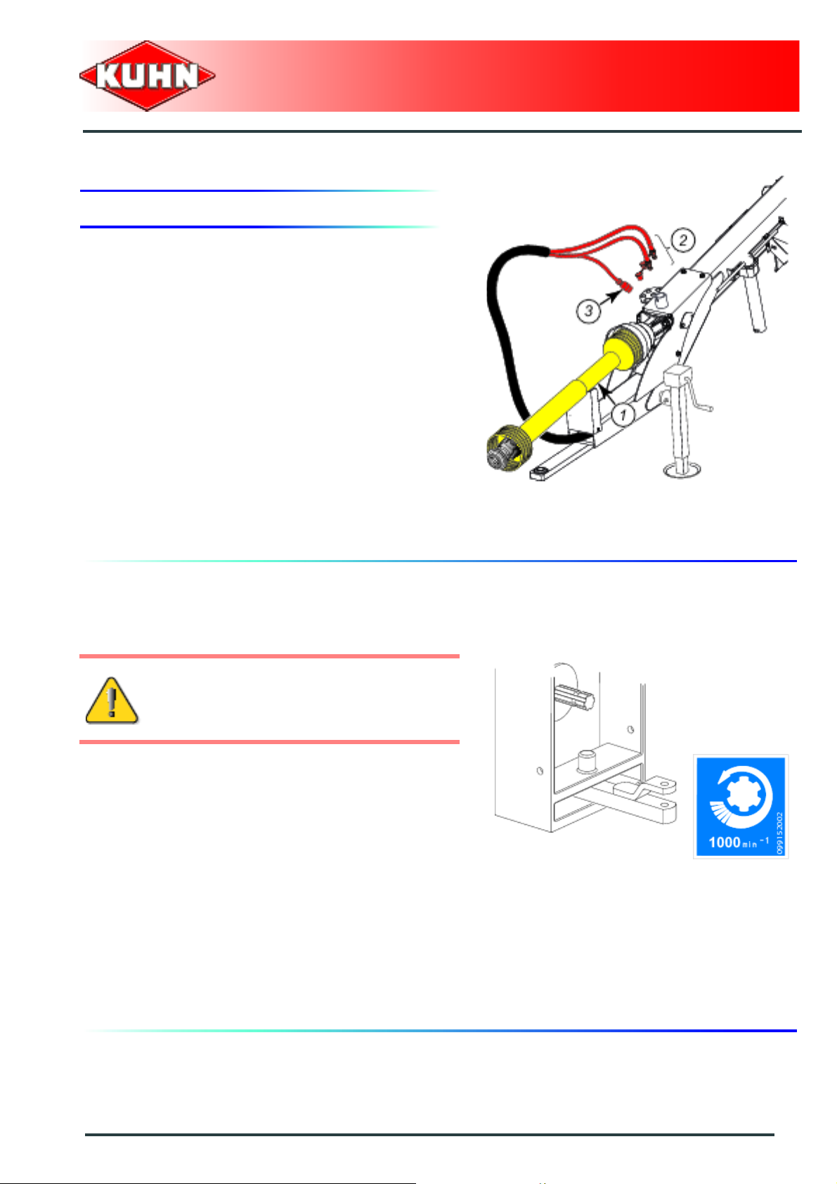
2. Coupling and uncoupling
Description of coupling elements
The machine is equipped with:
- A 1’’3/8 - 6 spline wide angle pto shaft (1).
- 2 hydraulic hoses (2).
- A 7-pin electric plug for the electrical signalling
equipment (3).
Gyrotedder
GF17002
Preparing the tractor
The machine adapts to tractors fitted with a pull bar or
piton-type coupling.
The tractor pull bar or piton-type coupling is
subject to a negative load when putting the
machine into work/transport position.
The tractor nominal PTO speed must be 1000 min
The tractor must be equipped with :
- 1 double acting hydraulic outlet.
- An electric 7-pin plug for the signalling equipment.
- 1 hydraulic circuit that allows a working pressure of
180 bar (2610 psi).
-1
.
Putting into service
25
Page 28

Linkage adjustment
Coupling to the pull bar:
- Adjust drawbar so that measure X equals 9 mm
(0.35’’).
Coupling to the piton-type coupling:
- Adjust drawbar so that measure X equals 309 mm
(1’).
Gyrotedder
GF17002
- Remove the 3 nuts (1).
- Remove bolts (2).
- Position drawbar in holes corresponding to the
required setting.
- Reinstall bolts (2).
- Reinstall the 3 nuts (1):
• Torque: 28 daN m (206 lbf ft).
The 3 screws must be fitted.
26
Putting into service
Page 29
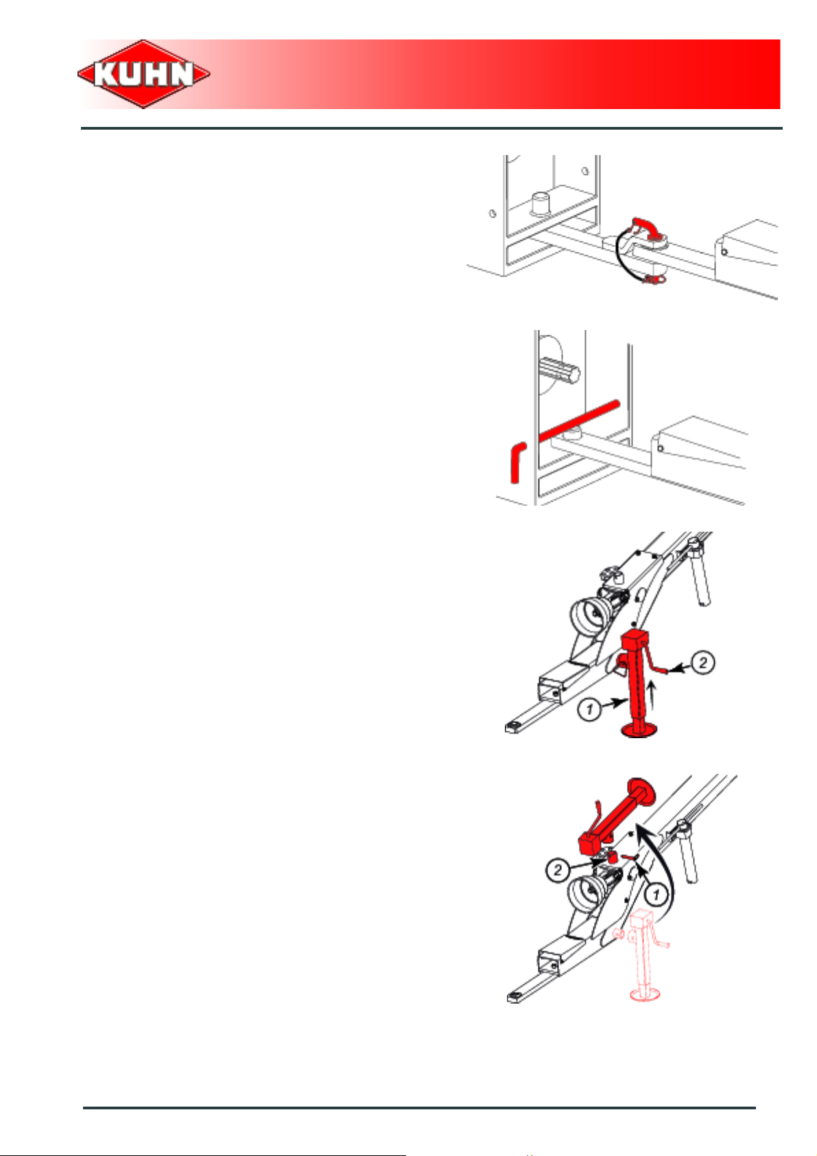
- Couple machine to tractor and secure hitch pin .
Gyrotedder
GF17002
- Raise parking stand (1) using crank (2).
- Remove pin (1).
- Remove and place parking stand in its holder (2).
- Lock parking stand using pin (1).
Putting into service
27
Page 30
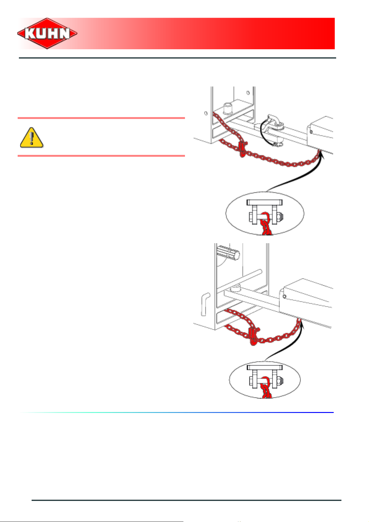
Safety chain
The machine is supplied with a ANSI/ASAE safety chain
type with a minimum ultimate system strength of
45 kN (10100 lbf).
The safety chain is intended to keep the
machine under control in the event of a loss
or failure of the hitch pin.
On the tractor side:
The safety chain must be tied around a tractor
attachment point other than the attachment bar.
Gyrotedder
GF17002
Machine side:
- Check safety chain for proper installation.
28
Putting into service
Page 31
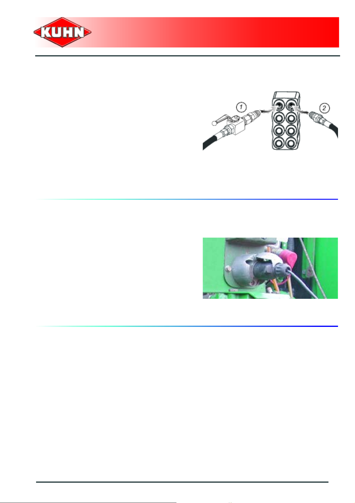
Hydraulic connections
The tractor must be fitted with a double acting hydraulic
outlet.
- Connect hydraulic hoses (1) and (2) to a do uble acting
outlet.
Gyrotedder
GF17002
Electrical connection
- Connect 7-pin plug to the tractor.
Putting into service
29
Page 32

Intermediate PTO shaft
Make sure that the PTO shaft is correctly
adjusted, to avoid premature wear and tear.
The tractor PTO stub must rotate at a speed of 1000 min-1.
Separate the two half PTO shafts and connect them to
the machine's input shaft and to the tractor PTO stub.
Check the length of the PTO shaft:
- Check the maximum overlap when the machine is in
work position and the tractor turned to the direction
which provides maximum overlap.
- When the PTO shaft is in its maximum overlap
position (retracted), tubes should not butt against the
yokes. As a safety measure, a clearance (L) of at least
25 mm (1’’) must be maintained.
- When the PTO shaft is in its maximum extended
position, the tube overlap must be more than
250 mm (10’’).
Gyrotedder
GF17002
If this is not the case:
• Mark length (H) to cut when the transmission is the
maximum overlap position
• Shorten the guard tubes and the transmission tubes
by the same length.
• Bevel and clean the tubes.
• Grease the inside of the outer tube.
Check that there is still a minimum overlap of
250 mm (10’’) when the machine is in working
position and the tractor in line with the machine.
30
Putting into service
Page 33

To avoid serious accidents, the PTO drive
shaft guards must be properly in place and
fixed with the chains provided.
Attach PTO shaft guard chain in hole (1) on machine
side.
Immediately replace any worn or damaged
guard.
Gyrotedder
GF17002
Lower PTO shaft support.
Putting into service
31
Page 34

Adjusting the machine
Adjusting the frame lowering speed
The machine adjustment must be made ever y
time another tractor is used.
When placing the machine in work position
(See section: Putting the machine into work position)
8 wheels (1) must touch the ground approximately at the
same time.
Gyrotedder
GF17002
32
Putting into service
Page 35

If necessary, adjust frame lowering speed:
- Rotate valve (1) clockwise to reduce fram e lowering
speed.
- Rotate valve (1) counterclockwise to increase frame
lowering speed.
Gyrotedder
GF17002
Putting into service
33
Page 36

Uncoupling the machine
Park the machine on an even fairly level
ground.
From the transport position:
- Block machine with wheel chocks (1).
Gyrotedder
GF17002
- Remove pin (1).
- Remove parking stand from its holder (2).
- Position parking stand in its parking holder.
- Insert pin (1).
- Adjust parking stand height using crank handle.
- Unfold pto shaft support (1).
- Uncouple and place PTO shaft in support (1).
34
Putting into service
Page 37

- Shut-off hydraulic valve.
- Disconnect and store hydraulic hoses on holder (1).
- Disconnect and store 7-pin plug in its holder (1).
Gyrotedder
GF17002
- Unhook safety chain.
- Remove hitch pin.
- Move forward with the tractor.
The machine is uncoupled.
Putting into service
35
Page 38

$Instructions for transport
Before placing the machine into transport
position:
- Disengage tractor PTO.
- Wait until the rotating parts have come
to a complete stop.
- Check that nobody is within the machine
pivoting area.
- If there is someone, make sure the
person moves away.
Gyrotedder
GF17002
1. Putting the machine into transport position
Place the machine on level ground.
On slopes, set the machine in work/transp ort
position with the machine downhill.
The tractor pull bar is subject to a negative
load when placing the machine in
work/transport position.
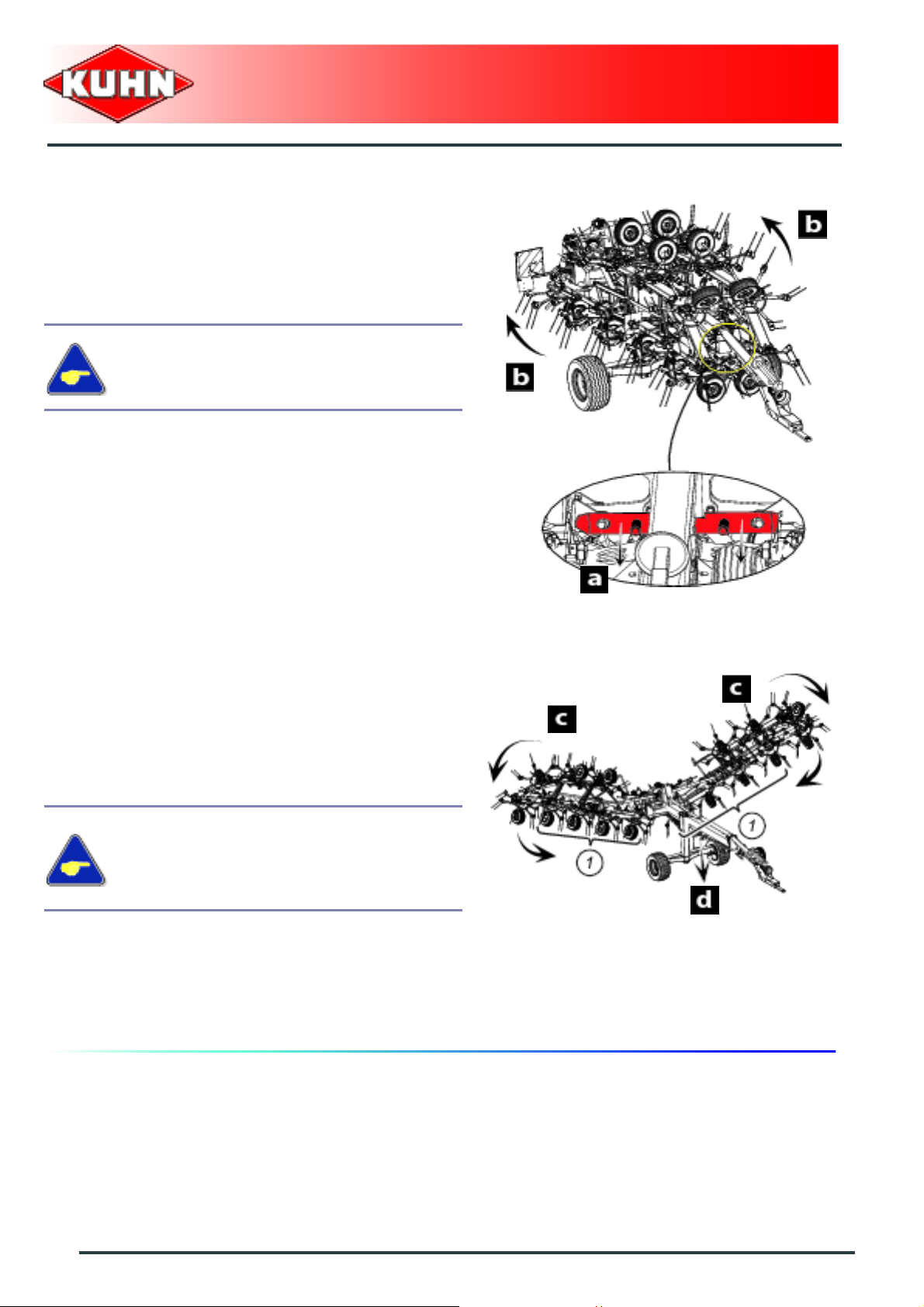
From the working position:
- Shift the tractor hydraulic valve:
• Simultaneous rotor indexing and outer arm folding
(b).
• All sections and the frame are lifted simultaneously
(c, d).
36
Instructions for transport
Page 39
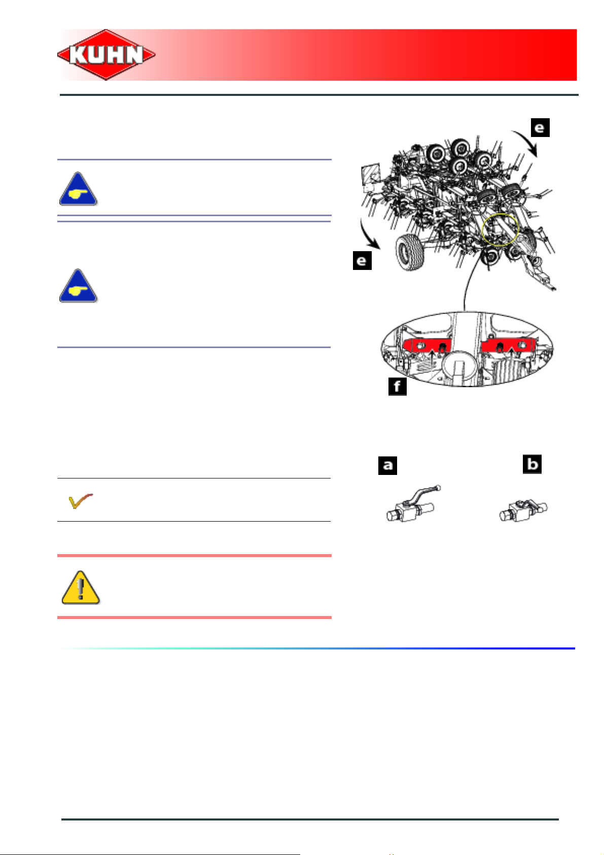
• All the sections fold along the frame (e).
• The sections automatically lock (f).
Depressurize the hydraulic circuit.
The left and right sections fold symmetrical ly
with regards to the main frame.
In the opposite case, operate the hydraulic
valve for opening/closing all the sections in
the opening position.
Maintain pressure until pivot cylinders have
reached travel end.
Repeat procedure for folding all sections.
Gyrotedder
GF17002
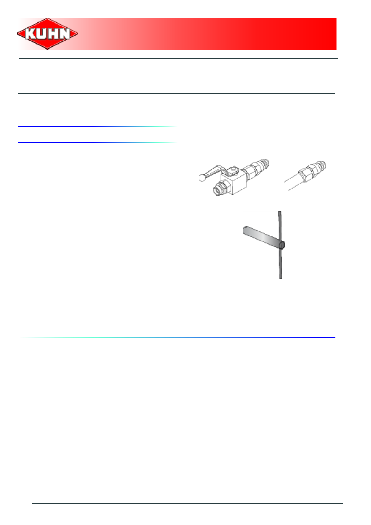
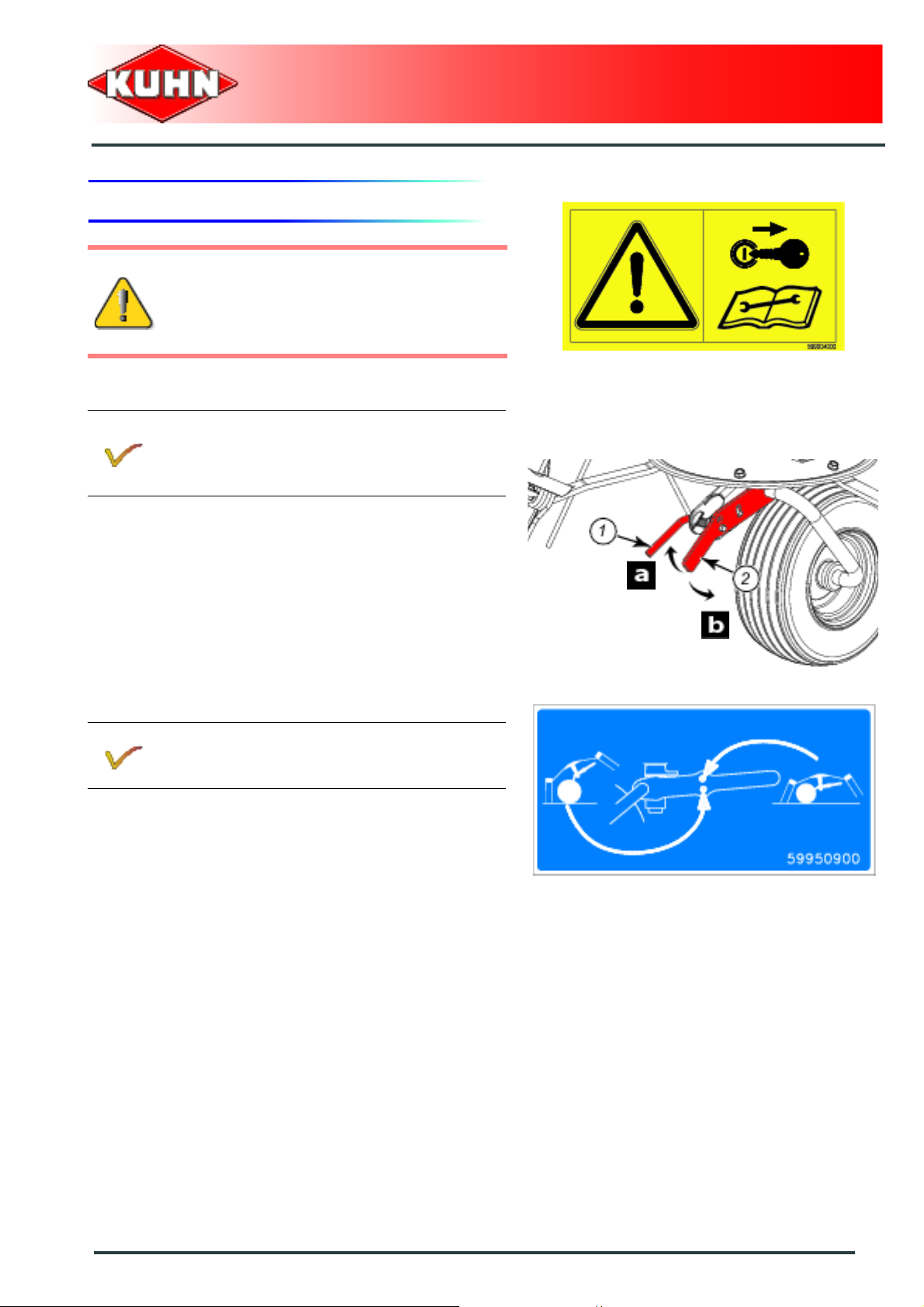
Locking:
See section: Check transport locks.
- Shut-off hydraulic hose valve for in and out folding of
the elements.
Position a: Circuit open.
Position b: Circuit closed.
The machine is in transport position.
Never engage the tractor PTO drive when t he
machine is in transport position.
Instructions for transport
37
Page 40

2. Conformity with the road regulations
Before driving the machine on public roads,
ensure that the machine complies with
current highway code regulations.
Specific requirements for Germany:
- Never tow the machine at a speed
exceeding 30 km/h (18.6 mph).
Instructions specific to France:
- Never tow the machine at a speed
exceeding 40 km/h (25 mph).
Gyrotedder
GF17002
Check that transport locks (1) are fully
engaged.
- Check that the light boards are clean and that the
lighting equipment functions before transporting the
machine on public roads.
Before going on public roads:
- Check that hose valve of elemen t in an d
out folding cylinder is shut-off.
Regularly check the tyre pressure.
38
Instructions for transport
Page 41

$Instructions for work
Before placing the machine in working
position:
- Check that nobody is within the machine
pivoting area.
- Wait until the rotating parts have come
to a complete stop.
- If there is someone, make sure the
person moves away.
1. Putting the machine into work position
Gyrotedder
GF17002
Place the machine on level ground.
On slopes, set the machine in work/transport
position with the machine downhill.
The tractor pull bar is subject to a negative
load when placing the machine in
work/transport position.
From the transport position:
- Open hydraulic hose valve for folding the elements in
and out.
Position a: Circuit open.
Position b: Circuit closed.
Instructions for work
39
Page 42
- Activate the transport/work cylinder control valve in
the "pivot into transport" position.
- Depressurize the hydraulic circuit.
- Activate the transport/work cylinder control valve in
the lower in work position.
• The machine unlocks automatically (a).
• All the elements unfold (b).
The left and right wings must fold
symmetrically with regards to the beam
Gyrotedder
GF17002
• Simultaneaous outer wing unfolding and frame
lowering (c, d).
• All wheels rest on the ground.
Make sure that the 8 wheels (1) touch the
ground approximately at the same time.
If necessary, adjust frame lowering speed.
Refer to "Adjusting the frame lowering
speed".
The machine is in working position.
40
Instructions for work
Page 43
2. Adjustments in working position
Before carrying out any maintenance or
repairs on the machine, switch off the tractor
engine, remove ignition key, wait until all
moving parts have come to a standstill and
apply park brake.
Pitch angle adjustment
Adjust to maximum pitch angle in large crop
quantities.
Adjust to minimum pitch angle in small crop
quantities.
- Slightly lift the machine from the ground.
- Rotate lever by a 1/4 turn to unlock adjustment system
(1).
- Lift crank (2) to obtain maximum pitch angle (a).
- Lower crank (2) to obtain minimum pitch angle (b).
- Rotate lever by a 1/4 turn to lock adjustment system
(1).
Gyrotedder
GF17002
Proceed same way on each rotor.
- Lower machine back on ground.
Instructions for work
41
Page 44

- Adjust pitch angle using adjustment crank so that the
tines slightly brush the soil (D).
The distance between tines and soil is a very
important factor with regards to the machine
work quality and tine service life.
Gyrotedder
GF17002
42
Instructions for work
Page 45

3. Machine use
Never raise the machine wings when the
rotors are blocked by forage.
First remove the forage that stops the rotor
rotation.
Groundspeed
The following factors determine the forward speed:
- The humidity level. (This factor is particularly
determining when wilting).
- The crop density.
- The crop composition (blade length).
- The ground contours.
Gyrotedder
GF17002
Below are a few recommendations for your information:
In dense and average length crop:
- When wilting a crop with high humidity level.
• We recommend a speed of 7 to 8 km/h (4.4 -
5 mph).
- When tedding a more or less dry crop.
• We recommend a speed of 8 to 10 km/h (5 -
6.3 mph).
The dryer the crop, the more the P TO speed must be
reduced.
For a very dense, humid crop composed of very long
blades, the forward speed must be reduced.
For difficult working conditions, it is
recommended to operate at a lower forward
speed.
Instructions for work
43
Page 46

The machine can turn at 180° without loosing working
width or time.
Gyrotedder
GF17002
44
Instructions for work
Page 47

$Optional equipment
1. Intermediate PTO transmission shaft with constant velocity joint
Kit no. 4800405
1"3/8 - 21 spline pto shaft.
Before using this equipment, read manual supplied with
the PTO.
Gyrotedder
GF17002
Lubrication
- Every 8 hours:
• U-joints (1).
• constant velocity joint (4).
- Every 20 hours:
• transmission tube (2).
- Every 40 hours:
• guide rings (3).
Central grease fitting (4) should be lubricated
when the double joint is straight (up to 30
pumps of grease may be required to fill the
CV joint reservoir correctly).
Optional equipment
45
Page 48

2. Deflector
Kit no. 1126500.
Adjustment
The deflector must be parallel to the ground and
positioned at a distance D of 50 mm (1.9’) with regards
to the ground.
We recommend to set the deflector in the
maximum forward position.
- Remove bolts (1).
- Adjust position of the deflector.
- Reinstall bolts (1):
• Torque: 5 daN m (3.7 lbf ft).
Gyrotedder
GF17002
When the machine is working position:
Shift tractor valve to place the deflector in the
required position.
Position a: Working along fences or ditches.
Position b: Normal work.
Respect a maximum work angle of 45°.
In order to prevent interferences between the
drawbar shift cylinder and the rotor, never
position the deflector at 90° with regards to
the direction of travel.
Otherwise, to reposition the drawbar shift
cylinder, activate tractor hydrualic valve in
the "putting into work" direction and
reposition deflector at 45° with regards to the
direction of travel.
46
Optional equipment
Page 49

3. Ball hitch drawbar diameter 80 mm (3.1’’)
Kit no. 1126470
Coupling the machine
- Couple the machine to the tractor.
- Pivot lock (2).
- Insert and lock pin (1).
Gyrotedder
GF17002
- Raise parking stand (1) using crank (2).
- Remove pin (1).
- Remove and place parking stand in its holder (2).
- Lock parking stand using pin (1).
Optional equipment
47
Page 50

Safety chain
The machine is supplied with a ANSI/ASAE safety chain
type with a minimum ultimate system strength of
45 kN (10100 lbf).
The safety chain is intended to keep the
machine under control in the event of a loss
or failure of the hitch pin.
On the tractor side:
The safety chain must be tied around a tractor
attachment point other than the attachment bar.
Gyrotedder
GF17002
Machine side:
- Check safety chain for proper installation.
Uncoupling the machine
Park the machine on an even fairly level
ground.
From the transport position:
- Block machine with wheel chocks (1).
48
Optional equipment
Page 51

- Remove pin (1).
- Remove parking stand from its holder (2).
- Position parking stand in its parking holder.
- Insert pin (1).
- Adjust parking stand height using crank handle.
- Unfold pto shaft support (1).
- Uncouple and place PTO shaft in support (1).
Gyrotedder
GF17002
- Shut-off hydraulic valve.
- Disconnect and store hydraulic hoses on holder (1).
- Disconnect and store 7-pin plug in its holder (1).
Optional equipment
49
Page 52

- Unhook safety chain.
- Unlock and remove pin (1).
- Pivot lock (2).
Gyrotedder
GF17002
- Raise parking stand (1) using crank (2).
- Move forward with the tractor.
The machine is uncoupled.
Grease
- Every 50 hours.
50
Optional equipment
Page 53

Before carrying out any maintenance or
repairs on the machine, switch off the tractor
engine, remove ignition key, wait until all
moving parts have come to a standstill and
apply park brake.
1. Frequency chart
Gyrotedder
GF17002
$Maintenance and storage
Lubrication
Oil change:
- Central gearbox.
Grease:
- The outer wing pivot pins.
- The pivot points.
- The "DIGIDRIVE" coupling fingers.
Oil:
- Cylinder pivot points.
- Pitch angle adjustment pivot points.
Maintenance
- Check that all nuts and bolts are sufficiently
tightened.
After the first
10 hours of
use
Every 50 hours
Every 100
hours or at the
end of the
season
33
3
3
3
- Check transport locks.
3
Maintenance and storage
51
Page 54

2. Lubrication
Before carrying out any maintenance or
repairs on the machine, switch off the trac tor
engine, remove ignition key, wait until all
moving parts have come to a standstill and
apply park brake.
The pictorials show the points to be greased (Part
no. 09905400).
- Clean grease nipples before greasing.
Gyrotedder
GF17002
Lubricate with SHELL multi-purpose grease
grade NLGI 2.
52
Maintenance and storage
Page 55

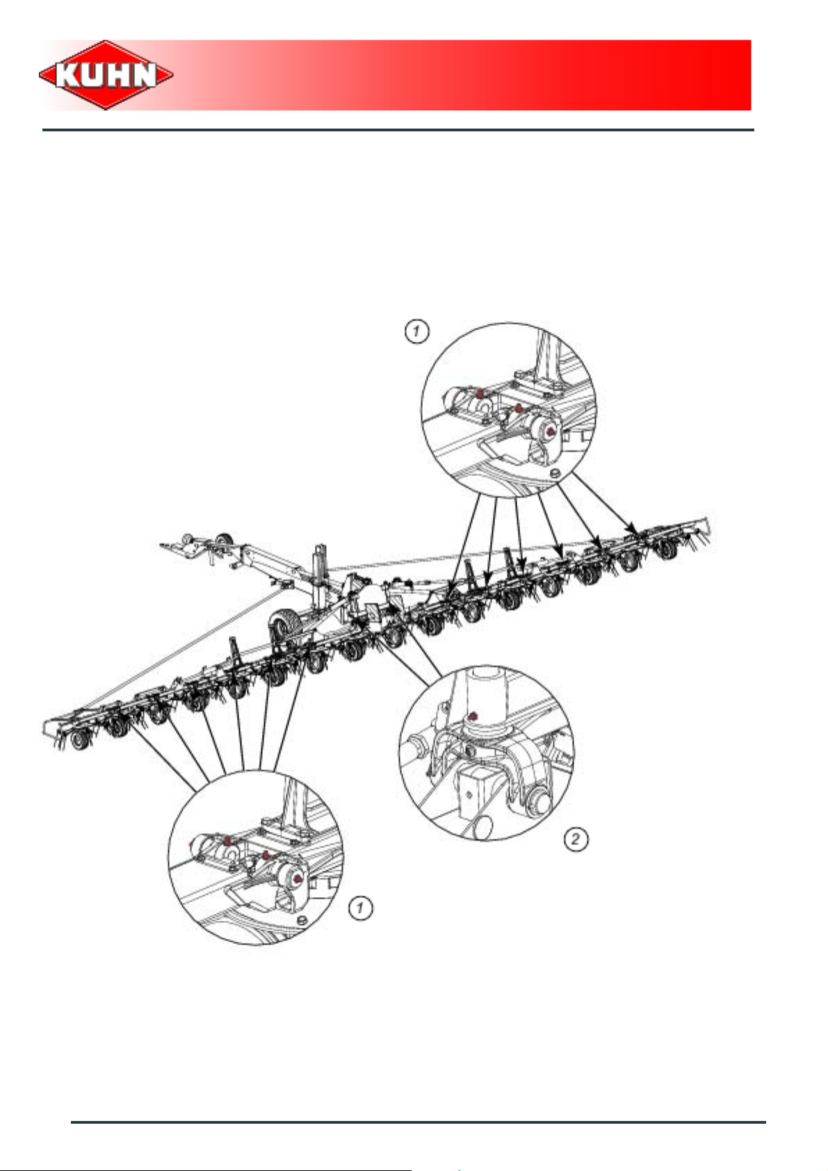
PTO shafts
Never disconnect side pto shafts without
having marked their position.
- Every 8 hours:
• U-joints (1).
• constant velocity joint (4).
- Every 20 hours:
• transmission tube (2).
- Every 40 hours:
• guide rings (3).
Central grease fitting (4) should be lubricated
when the double joint is straight (up to 30
pumps of grease may be required to fill the
CV joint reservoir correctly).
Gyrotedder
GF17002
Maintenance and storage
53
Page 56

- Every 8 hours:
• U-joints (1).
- Every 20 hours:
• transmission tube (2).
- Every 40 hours:
• guide rings (3).
Gyrotedder
GF17002
54
Maintenance and storage
Page 57

Central gearbox draining
Before draining oil, operate the machine for a
few minutes so that the oil warms up.
The main gearbox is lubricated with 1 L (0.26 U S gal) of SHELL SPIRAX A extreme-pressure gear oil
with viscosity grade 80W90 and API grade GL5.
- Remove filler plug (2) and its washer.
- Place a container of sufficient capacity under drain
plug (1).
- Remove drain plug (1) and its washer.
- Allow oil to drain completely.
- Wait for dripping to stop.
- Clean and reinstall drain plug (1) and its washer.
Replace if necessary.
- Pour the prescribed oil quantity and quality through
the opening of the filler plug (2).
Gyrotedder
GF17002
- Place central gearbox in horizontal position.
- Check the oil level:
• The oil must reach the lower edge of the filling hole.
- Top up if necessary.
- Clean and reinstall filler plug (2) and its washer.
Replace if necessary.
Maintenance and storage
55
Page 58
Grease
- The outer wing pivot pins (1).
- The pivot points. (2)
Gyrotedder
GF17002
56
Maintenance and storage
Page 59
- The "DIGIDRIVE" coupling fingers.
Gyrotedder
GF17002
Maintenance and storage
57
Page 60

Oil
Oil with SHELL SAE 90 gear oil.
- Cylinder pivot points (1).
- Pitch angle adjustment pivot points (2).
- Pivot points.
Gyrotedder
GF17002
58
Maintenance and storage
Page 61

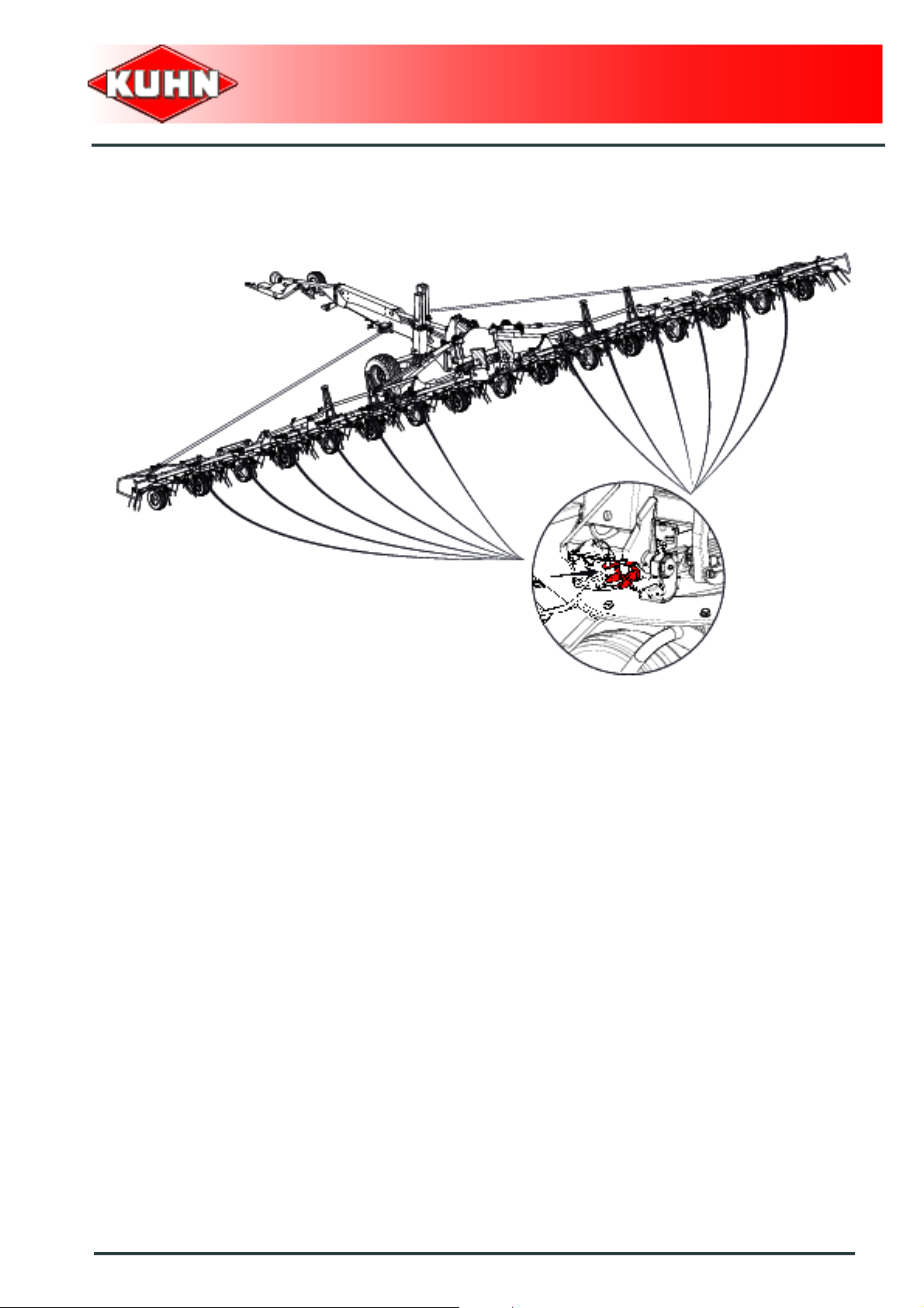
3. Maintenance
Side gearboxes
The side gearboxes are lubricated for life and do not
require regular maintenance.
Each gearbox is lubricated with 0.8 kg (1.8 lb) of
SHELL ALVANIA WRO semi-fluid grease with
viscosity grade NLGI 0.
Gyrotedder
GF17002
Checking the fixing elements
- Check transport wheel nuts (1) for tightness:
• Torque: 27 daN m (199 lbf ft)
- Check tightness of drawbar attachment screws (2):
• Torque: 28 daN m (206 lbf ft).
Maintenance and storage
59
Page 62
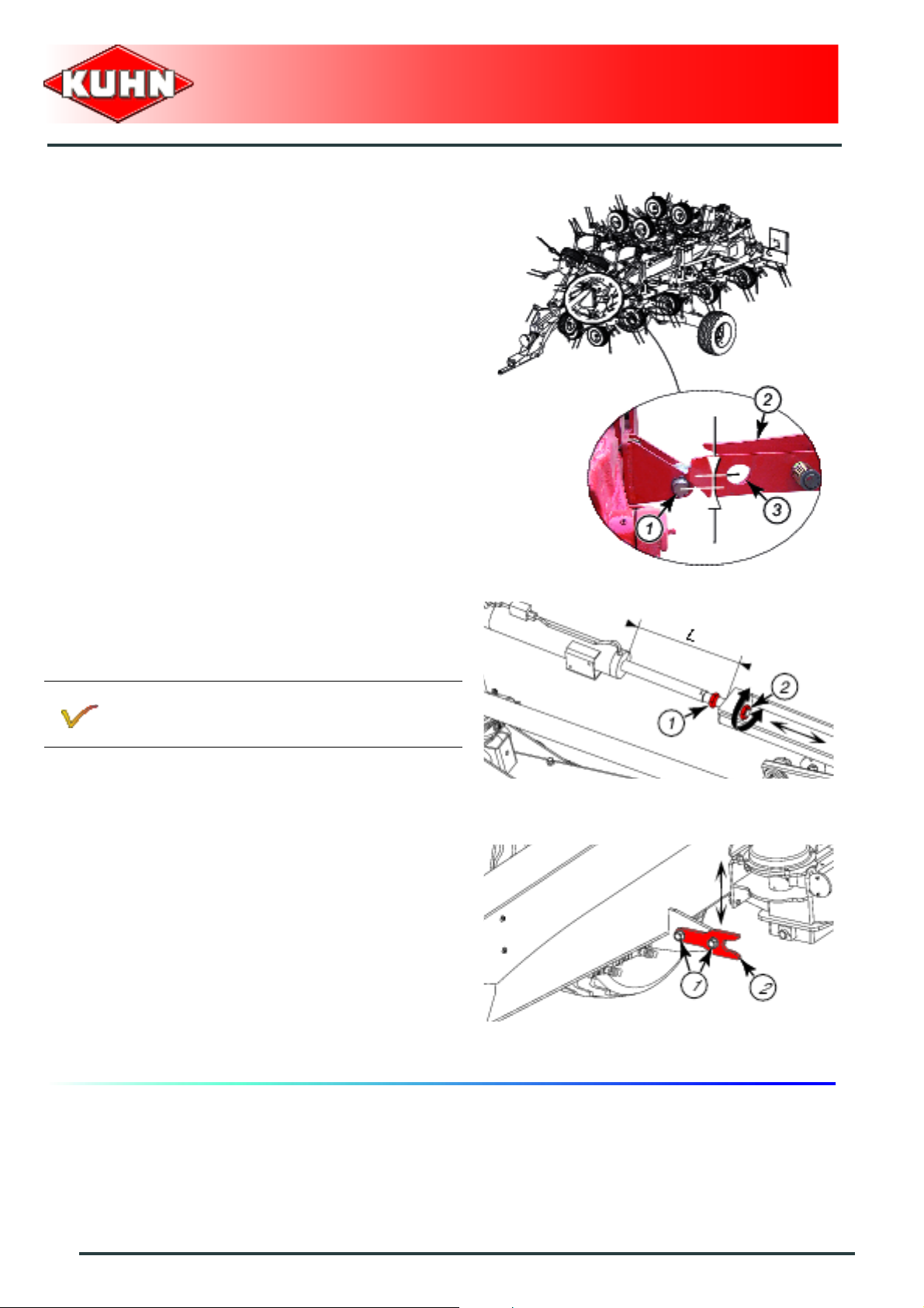
Check transport locks
After a few hours work, check locking pin (1) is in line
with latch (2) and oblong hole (3), adjust if necessary.
Gyrotedder
GF17002
Adjustment
- Loosen nut (1).
• Loosen nut (2) to reduce length L.
• Tighten nut (2) to increase length L.
Turning the nut once modifies the height offset of
the locking yoke by approximately 1 cm (0.4’’).
- Tighten nut (1).
- Loosen nuts (1).
- Place the machine in transport position.
- The position of intermediate yokes (2) is adjusted
using the fingers of the intermediate fra m es.
- Tighten nuts (1).
60
Maintenance and storage
Page 63
Replacing a tine
Before leaving the tractor or before
adjusting, maintaining or repairing the
machine, disengage the PTO drive, turn off
the engine, remove ignition key and wait until
all moving parts have come to a complete
stop and apply park brake.
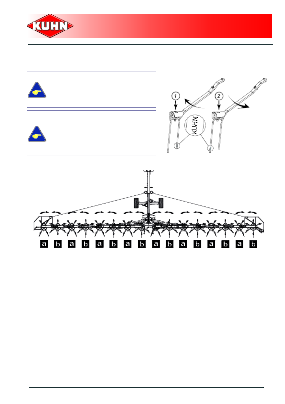
2 types of tines are fitted on the machine:
- Tines (1) for rotors rotating clockwise
- Tines (2) for rotors rotating
Check that the tines are f itted properly with
regards to the rotor direction of rotation.
Gyrotedder
GF17002
(a).
counterclockwise (b).
Maintenance and storage
61
Page 64

From the working position:
- Remove attachment screw (1).
Respect mounting instructions so that the crop's
pressure (a) closes the coils.
Gyrotedder
GF17002
- Replace tine.
Check attachment bolt, washer and nut. Replace
if necessary.
- Reassemble the unit.
Check that the tine is properly embedded in
the tine arm.
- Tighten attachment screw:
• Torque: 20 daN m (148 lbf ft).
62
Maintenance and storage
Page 65

Tyre pressure
- Transport wheels (1): 2.5 bar (37 psi).
- Wheels (Central rotors) (3): 2.0 ba r (2 9 psi).
- Rotor wheels (2): 1.5 bar (22 psi).
Gyrotedder
GF17002
4. Storage
At the end of each season:
- Clean the machine thoroughly.
- Fully lubricate the machine.
- Check tyre pressure:
• Transport wheels: 2.5 bar (37 psi).
• Wheels (Central rotors): 2.0 bar (29 psi).
• Rotor wheels: 1.5 bar (22 psi).
- Touch up any areas of damaged paintwork.
- Check and replace worn or damaged tines.
- Put the machine under cover in a dry place.
At the start of each season:
- Re-read the operators' manual.
- Check tyre pressure:
• Transport wheels: 2.5 bar (37 psi).
• Wheels (Central rotors): 2.0 bar (29 psi).
• Rotor wheels: 1.5 bar (22 psi).
- Check that all nuts and bolts are sufficiently tightened.
- Make sure that all protection devices are in place and
in good condition.
Maintenance and storage
63
Page 66

$Limited warranty
Gyrotedder
GF17002
64
Limited warranty
Page 67

Gyrotedder
GF17002
Limited warranty
65
Page 68

Page 69

Page 70

Page 71

Page 72

 Loading...