

Page 1

OPERATOR'S MANUAL
KN201AGB E
Gyrotedder
GF10802T
KN201AGB E
- English - 07-2010
Page 2

Page 3

Gyrotedder
GF10802T
$Dear Owner
In buying a Kuhn machine you have chosen wisely. Into it have gone years of thought, research and
improvement. You will find, as have thousands of owners all over the world, that you have the best that
engineering skill and actual field testing can produce. You have purchased a dependable machine, but only
through proper care and operation can you expect to receive the performance and long service built into it.
This manual contains all the necessary information for you to receive full efficiency from your machine. The
performance you get from this machine is largely dependent on how well you read and understand th is manual
and apply this knowledge. Please DO NOT ASSUME YOU KNOW HOW TO OPERATE AND MAINTAIN YOUR
MACHINE before reading this manual carefully. KEEP THIS MANUAL AVAILABLE FOR REFERENCE. Pass
it on to the next owner if you re-sell the machine.
Your KUHN dealer can offer a complete line of genuine KUHN service parts. These parts ar e manufactured and
carefully inspected in the same factory that builds the machine to assure high quality and accurate fitting of any
necessary replacements.
About improvements
We are continually striving to improve our products. It therefore reserves the right to make improvements or
changes when it becomes practical to do so, without incurring any obligations to make changes or additions to
the equipment sold previously.
Designated use of the machine
The GF10802T gyrotedder must only be used for the purpose for which it was manufactured: spreading and
tedding previously cut forage or straw. It can also be used to form small windrows in order to limit the exposure
of crop to dew at night.
Document illustrations
The illustrations in this manual may be based on one typ e of machine only. However, all instructions apply to all
machines covered in this manual.
Dear Owner
1
Page 4

Gyrotedder
GF10802T
$Contents
Dear Owner.....................................................................................................................1
Contents .........................................................................................................................2
Identification of the machine.........................................................................................4
Rear view (transport position).........................................................................................................4
Front view (working position) .........................................................................................................4
Model identification plate ................................................................................................................5
Safety...............................................................................................................................6
Description of symbols used in this document.............................................................................6
Safety instructions...........................................................................................................................7
Location and description of safety decals on the machine .......................................................18
Road safety equipment and recommendations...........................................................................21
Machine specifications................................................................................................23
Description and glossary...............................................................................................................23
Technical specifications......... .... ... ... .......................................... ... .... ... .........................................24
Sound levels ......... ... ... .... ... ... ... .... ...................................... .... ... ... ... .... ... ... ... ...................................26
Putting into service......................................................................................................27
Description of control elements....................................................................................................27
Coupling and uncoupling..............................................................................................................28
Instructions for transport............................................................................................36
2
Putting the machine into transport position................................................................................36
Conformity with the road regulations...........................................................................................38
Contents
Page 5

Gyrotedder
GF10802T
Instructions for work...................................................................................................39
Putting the machine into work position.......... ... ..........................................................................39
Adjustments in working position..................................................................................................41
Machine use....................................................................................................................................43
Optional equipment.....................................................................................................45
Spare wheel .......... ... ... ....................................... ... ... .... ... ... ....................................... ... ...................45
DUPLEX gearbox............................................................................................................................45
Double prop wheels.......................................................................................................................46
Maintenance and storage............................................................................................ 48
Frequency chart .............................................................................................................................48
Lubrication............................................................................................ ..........................................49
Maintenance....................................................................................................................................56
Storage............................................................................................................................................59
Appendix ......................................................................................................................60
Calculating the load on an axle.....................................................................................................60
Limited warranty..........................................................................................................66
Contents
3
Page 6
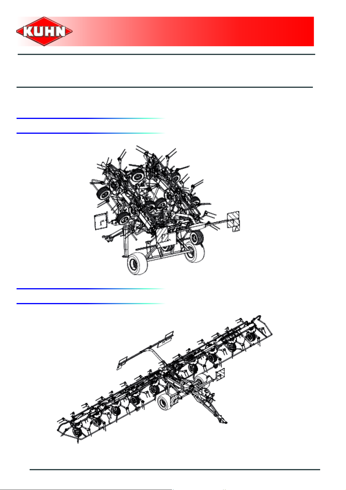
$Identification of the machine
1. Rear view (transport position)
Gyrotedder
GF10802T
2. Front view (working position)
4
Identification of the machine
Page 7
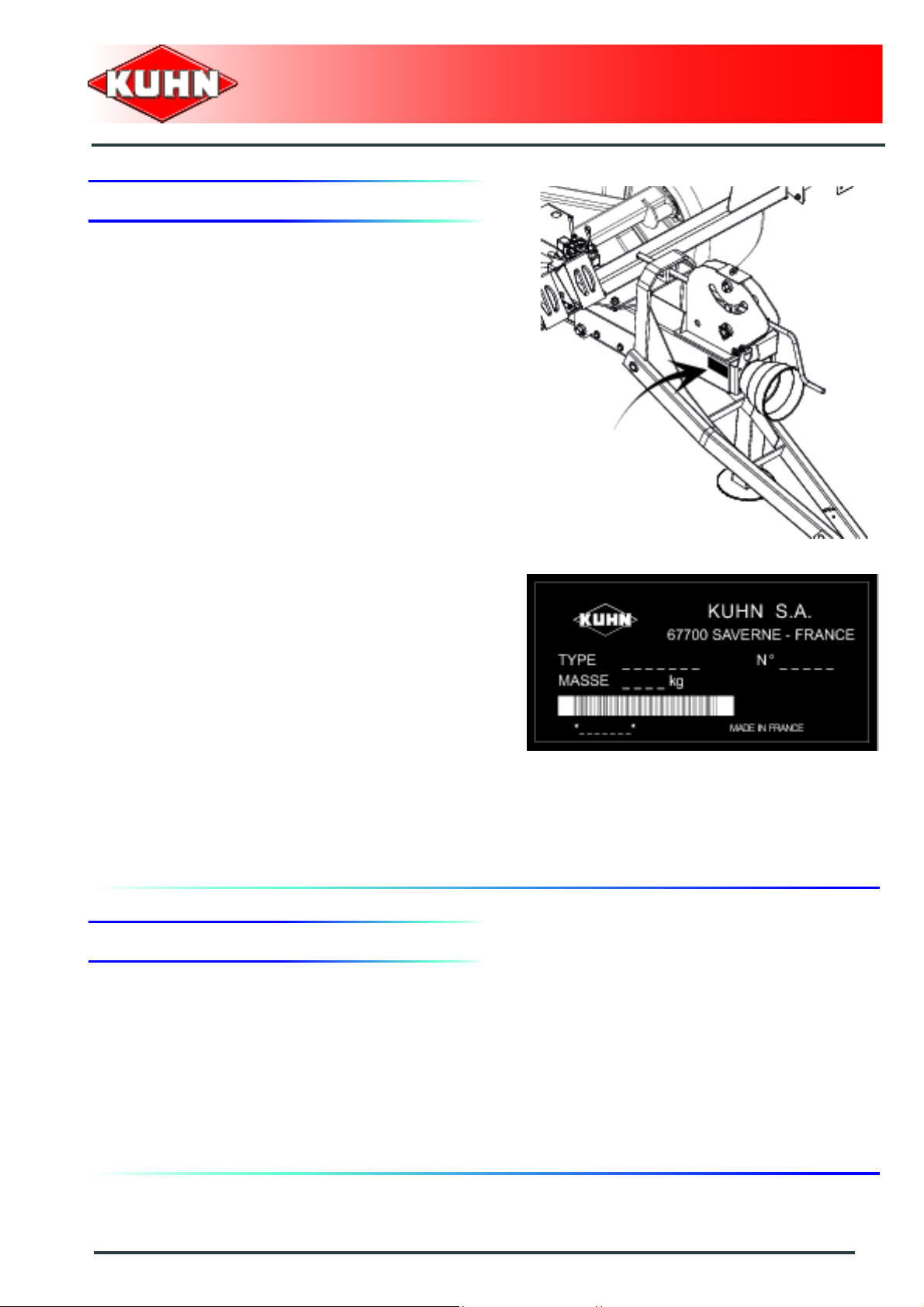
3. Model identification plate
Please write below the type and serial number of the
machine. This information is to be indicated to the dealer
for all spare parts orders.
Gyrotedder
GF10802T
Type: GF10802T
Serial no.:
4. Optional equipment
Tick box corresponding to the equipment fitted on your
machine:
Kit no. 1126330: Spare wheel
Kit no. 1126540: DUPLEX gearbox
Kit no. 1126550: Double prop wheels
Identification of the machine
5
Page 8
$Safety
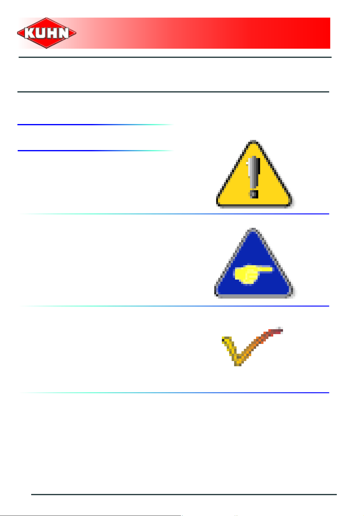
1. Description of symbols used in this document
This symbol indicates a potentially hazardous situation
that if not avoided, could result in serious bodily injury.
Gyrotedder
GF10802T
This symbol is used to identify special instructions or
procedures which, if not followed strictly, could result in
machinery damage.
This symbol is used to communicate technical
information of particular interest.
6
Safety
Page 9
Gyrotedder
GF10802T
2. Safety instructions
Introduction
The machine must only be operated, maintained and repaired by competent persons who are familiar with
machines' specifications and operation and aware of safety regulations fo r preventing accidents.
The operator must imperatively respect safety instructions in this manual and in the warnings posted on the
machine. The operator is also obliged to respect current le gislation concerning accident prevention, wo rk safety
and public traffic circulation.
Designated use of the machine also means following operation, maintenance and repair recommendations
given by the manufacturer, and using only genuine spare parts, equipment a nd acce sso ries, as r ecom mended
by the manufacturer.
The manufacturer is not held liable for any damage resulting from machine applications other than those
specified by the manufacturer. Any use other than the designated operation is at the risk and responsibility of
the operator.
The manufacturer is not held liable for any damage or accident re sulting from machine modifications carried out
by the operator himself or by a third party without previous written agreement from the manufacturer.
Read and follow the safety instructions
Before using the machine, carefully read all the safety
instructions in this manual and the warnings placed on
the machine.
Before starting work, the operator must be familiar with
all machine controls, handling devices and their
functions. It is too late to learn once work has been
started!
Never let anyone operate the machine who is not traine d
to do so.
Should you have any difficulties in understanding certain
parts in this manual, please contact your KUHN dealer.
Precautions to be taken before carrying out
any operations on the machine
Before leaving the tractor or before adjusting,
maintaining or repairing the machine, disengage the
PTO drive, turn off the engine, remove ignition key and
wait until all moving parts have come to a complete stop
and apply park brake.
Safety
7
Page 10
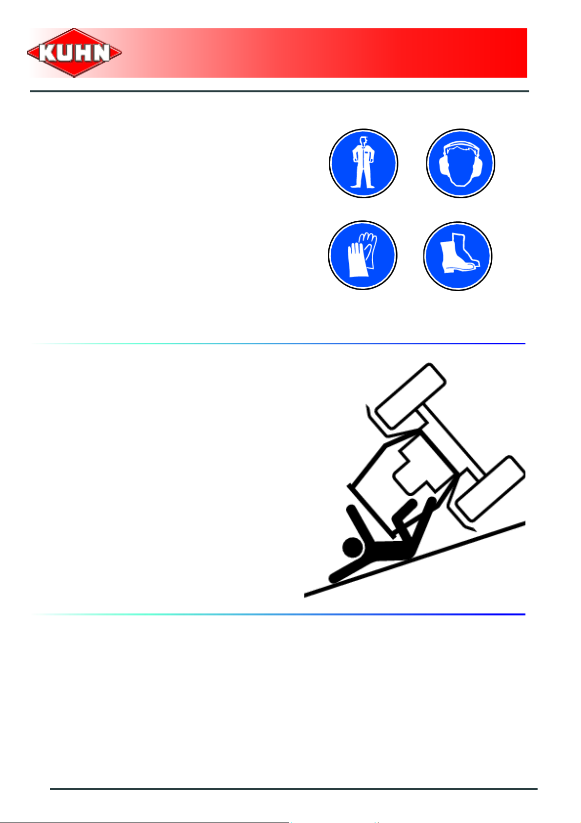
Precautions to take before using the
machine
Do not wear loose clothing which could become caught
up in moving parts.
Wear the appropriate protective clothing for the work in
hand (gloves, shoes, goggles, helmet, ear defenders,
etc.).
Ensure that all operating controls (ropes, cables, rods,
etc) are placed so as they cannot be operated
unintentionally and cause damage or injury.
Before operating the machine, check tightness of nuts
and bolts, particularly on fixing elements (tines, forks,
blades, knives, etc). Retighten if necessary.
Before operating the machine, ensure that all the safety
guards are firmly in place and in good condition.
Immediately replace any worn or damaged guard.
Gyrotedder
GF10802T
Precautions when driving
Tractor handling, stability, performance and braking
efficiency are all affected by weight distribution, trailed or
mounted implements, additional ballast and driving
conditions. It is therefore of great importance that the
operator exercises caution in every given situation.
Groundspeed must be adapted to ground conditions as
well as to roads and paths. Always avoid abrupt change s
of direction.
Be particularly cautious when turning corners, paying
attention to machine overhang, length, height and
weight.
Never use a narrow track tractor on very uneven or
steeply sloping ground.
Never leave the tractor seat while the machine is
operating.
Carrying people or animals on the machine when
working or in transport is strictly forbidden.
8
Safety
Page 11
Precautions when driving on public roads
Dimensions
Depending on the dimensions of the machine, contact
the relevant authorities to ensure that it can be legally
transported on public roads.
If the machine is over the maximum legal size, follow the
local regulations for special transportation of oversize
equipment.
Transport position
Before transporting the machine on public roads, place
the machine into its transport position, according to the
instructions in this manual.
Lights and indicators
Before transporting the machine on public road s, ensure
that all legally required lightings and signallings are in
place.
Ensure that lightings and signallings are clean and in
good working order. Replace any missing or broken
equipment.
Gyrotedder
GF10802T
Always obey current regulations for driving
on roads.
Gross weight and weight per axle
The drawings are not legally binding, their only aim is to illustrate the method to use.
Prior to driving on public roads, check t hat criteria are met t o be in conformity with the count rie's
regulations:
- When coupling a tool to the front and rear 3-point lift linkage, the maximum authorized
payload must not be exceeded.
- When coupling tools to the front and rear 3-point lift linkages, the maximum load on each
axle's tires must not be exceeded.
- The load on the tractor front axle must always represent 2 0 % of the tr actor unladen we ight.
For machines with hoppers or tanks:
- If the total unit weight exceeds the tractor Gross Combined Weight Rating in accordance
with the countrie's legislation, empty the hopper to travel on public roads.
- In any case, we recommend to travel on public roads with empty hoppers and tanks .
Safety
9
Page 12
Gyrotedder
GF10802T
Description of symbols
Description Units Description
T kg Tractor unladen weight
PTAC kg Gross Combined Weight Rating
T1 kg Unladen load on tractor front axle
T2 kg Empty load on tractor rear axle
t kg Axle loads (Tractor + machine)
t1 kg Load on front axle (Tractor + machine)
t2 kg Load on rear axle (Tractor + machine)
t1 max kg Maximum load authorized on the tractor front axle according to the tires
t2 max kg Maximum load authorized on the tractor rear axle according to the tires
M1 kg Total weight of front tool or front ballast
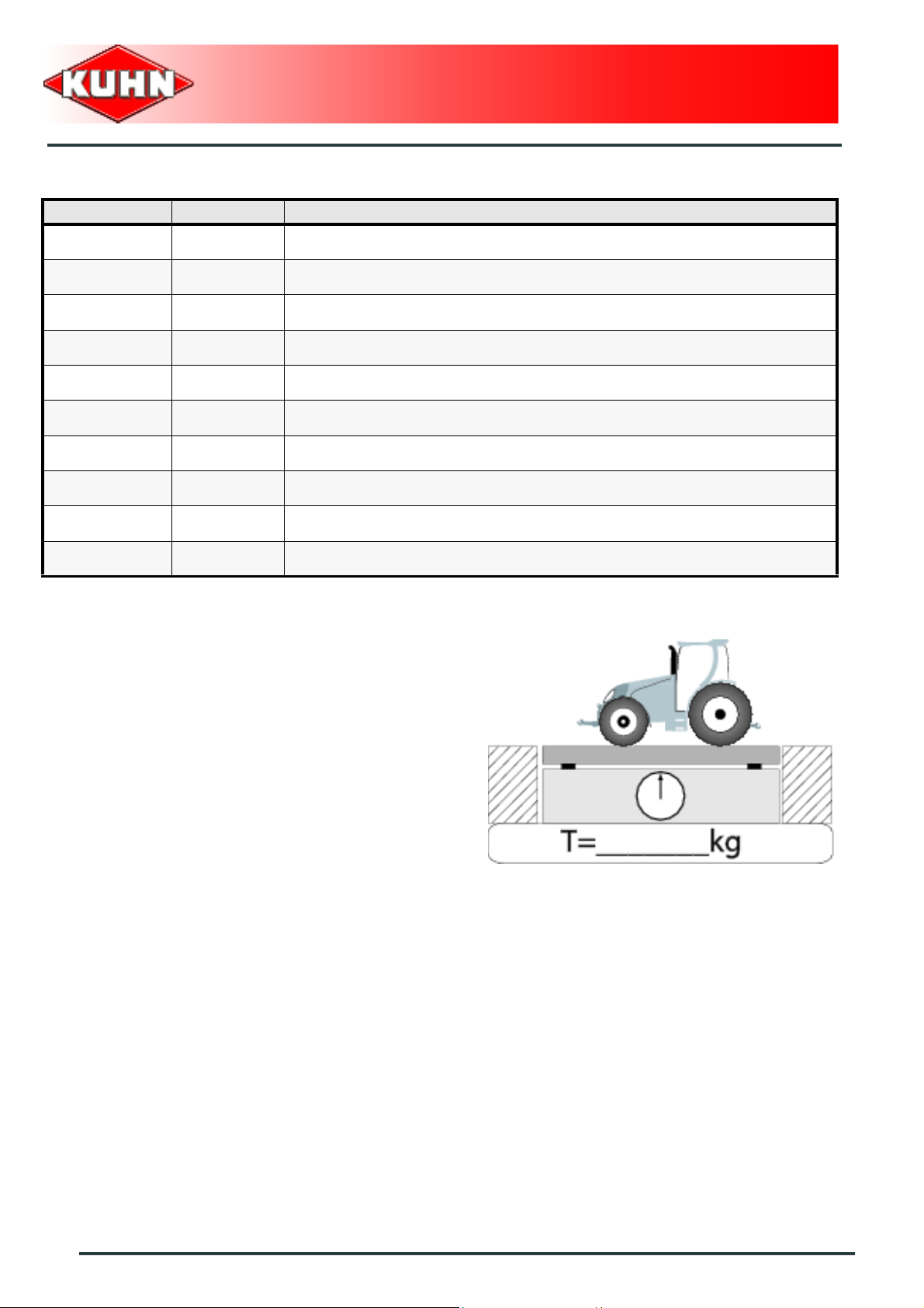
Stage 1:
To measure:
- Tractor tare (T).
10
Safety
Page 13
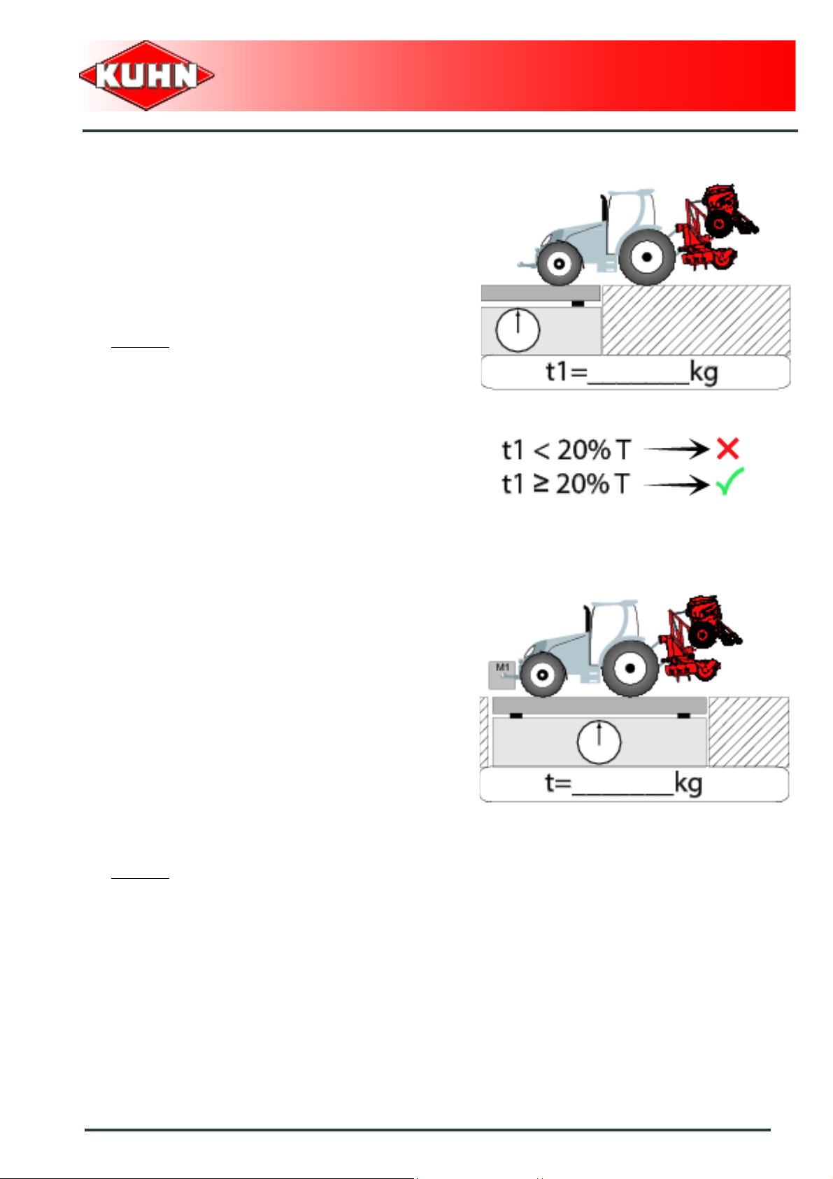
Stage 2:
- Couple the machine to the tractor.
To measure:
- Load on front axle (t1):
• Tractor + machine (transport position).
To do:
- If the front axle load (t1) is below 20% of the tractor
tare (T), add ballast weights (M1) to exceed the
minimum load on the front axle.
Example:
• (T) = 7500 kg (16535 lb)
• The front axle load must be of minimum 1500 kg
(3300 lb).(20% of T)
• (t1) = 700 kg (1545 lb).
• 700 kg (1545 lb) < 1500 kg (3300 lb).
• Add ballast weights until the minimum front axle
load is exceeded.
• Repeat checking procedure.
Gyrotedder
GF10802T
Stage 3:
To measure:
- Total weight (t):
• Tractor + machine (transport position).
• Ballast weights.
Checking:
- To go to the next stage:
• Check in the tractor's operator's manual that the
value measured is below the tractor's Gross
Combined Weight Rating.
To do:
- If t < PTAC go to the next stage.
- If the total unit weight exceeds the tractor Gross
Combined Weight Rating in accordance with the
countrie's legislation, empty the hopper to travel on
public roads.
Example:
• (t) = 10000 kg (24250 lb)
• PTAC = 13000 kg .
• t < PTAC : Go to the next stage.
Safety
11
Page 14
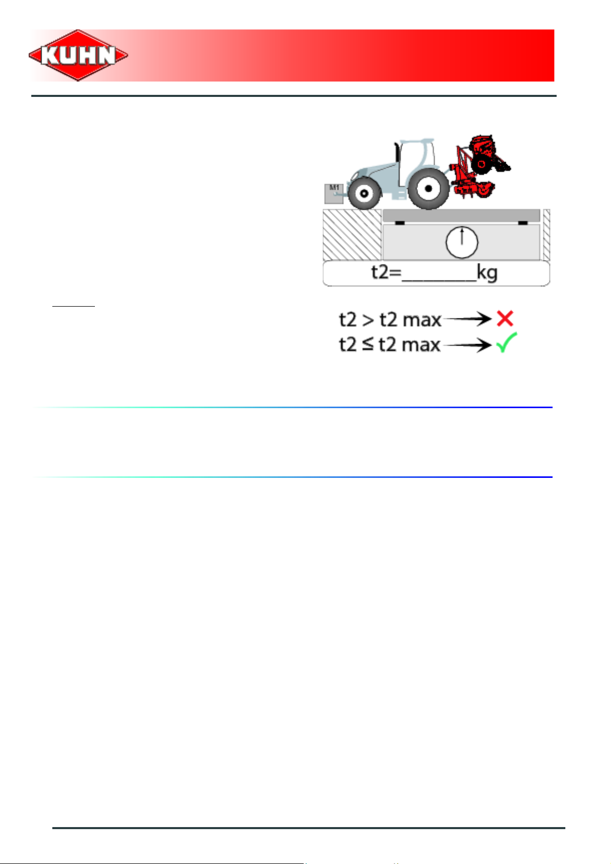
Stage 4:
To measure:
- Load on rear axle (t2):
• Tractor + machine (transport position).
• Ballast weights.
Checking:
- Check in the tractor's operator's manual that the value
measured is below the maximum allowed tractor rear
axle load.
- Check that tyre and rim specifiations are in conformity
with the requirements of the tractor manufacturer.
Example:
• Load on rear axle (t2) = 8500 kg (18740 lb)
• Check in the tractor's operator's manual that the
value measured is below the maximum allowed
tractor rear axle load.
• Check that tyre and rim specifiations are in
conformity with the requirements of the tractor
manufacturer.
Gyrotedder
GF10802T
Maximum speed
Always keep to the legal speed limit for driving a tractormachine assembly on public roads.
12
Safety
Page 15
Precautions when coupling
Before attaching the machine, make sure that it cannot
accidentally start moving (chock the wheels) and that the
parking stand is in the right position.
The machine must only be attached to the hitch points
provided for this purpose.
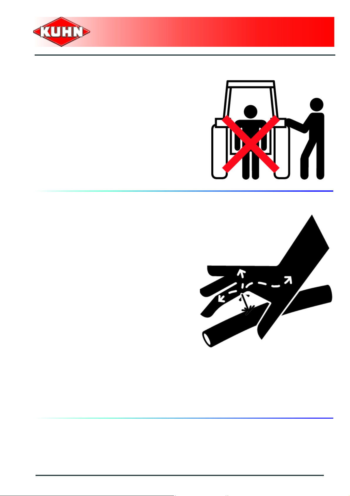
Never stand between the tractor and the machine when
operating the three point linkage.
Do not stand between the tractor and the machine
without ensuring that the parking brake is applied.
Hydraulic circuit
Gyrotedder
GF10802T
Caution! The hydraulic circuit is under high pressure.
Maximum pressure at work: 200 bar.
Before connecting hoses to the tractor hydraulics,
ensure that tractor and machine circuits are not under
pressure.Before disconnecting a hose, depressurize the
hydraulic circuit.
To avoid making incorrect connectio ns, mark hydraulic
couplers and corresponding hoses with colors.
WARNING! Functions could be reversed (for example:
lift/lower) and cause accidents.
Regularly check the hydraulic hoses. In case of normal
wear, replace the hydraulic hoses every 5 years.
Damaged or worn hoses must immediately be r eplaced.
When replacing the hydraulic hoses, only use hoses with
the specification recommended by the manufacturer of
the machine.
To locate a leak, use appropriate means. Protect body
and hands from liquid under pressure.
Any liquid under pressure (particularly oil from
hydraulics) can penetrate the skin and cause severe
injury. If injured, see a doctor immediately, there could
be danger of infection.
Before any adjustments, maintenance or repairs are
carried out, lower the machine to the ground,
depressurize the hydraulics, turn off the engine, remove
ignition key and wait until all moving parts have come to
a complete stop.
Safety
13
Page 16
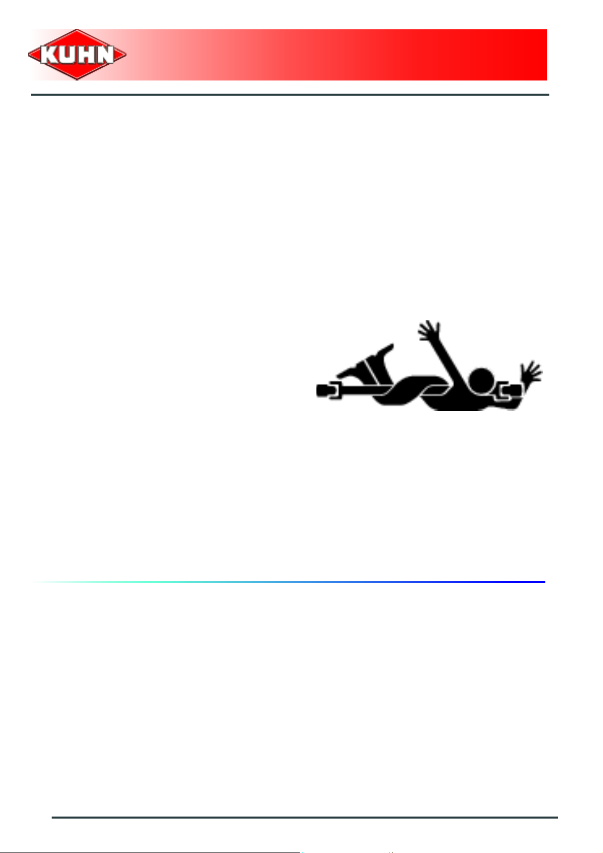
PTO shaft
Use only PTO shafts supplied with the machine or
recommended by the manufacturer.
The protective shield of the tractor PTO stub, the PTO
shaft guards and the protective covering of the machine
input shaft must always be in place and in good
condition.
Make sure that the PTO shaft guards are secured with
the safety chains provided.
Any worn or damaged guards must be replaced
immediately.A worn guard or an unprotected PTO shaft
can cause a serious or even a lethal accident.
Do not wear loose clothing that could be caught in the
rotating PTO shaft.
Before attaching or removing a PTO shaft, or before
doing any work on the machine, disengage the PTO
drive, turn off the engine, remove ignition key and wait
for all moving parts have come to a complete stop.
If the primary PTO shaft is equipped with a slip clutch or
a free wheel, these must be fitted on the machine side.
Ensure that the PTO shaft is always correctly fitted and
locked into place.
Before connecting the PTO shaft, ensure that the PTO
speed (rotational frequency) and directions of rotation
are in line with manufacturer's recommendat ion s.
Before engaging the PTO drive, make sure all people
and animals are clear from the machine. Never engage
the PTO drive when the tractor engine is stopped.
When uncoupling the machine, rest the PTO shaft on the
support specially provided, and replace protective cover
on the PTO stub of the tractor.
Read and follow the instructions in the operator's manual
provided with the PTO shaft.
Gyrotedder
GF10802T
14
Safety
Page 17

Precautions during manoeuvres
When moving the machine from the transport position to
the working position and vice versa, make sure that
nobody is within the machine pivoting area.
Remote controlled components
Danger of crushing and shearing can exist when
components are operated by hydraulic or pneumatic
controls. Keep away from these danger zones.
Tyres
Regularly check the tyre pressure. Respect
manufacturers' recommendations on pressure.
Assembly, disassembly and repair of wheels and tyres
must only be carried out by competent persons who are
equipped with standardized tools. Before any work is
performed on the wheels, ensure that the machine rests
on the ground and is perfectly stable so that it cannot
move accidentally (put chocks in place).
Gyrotedder
GF10802T
Safety decals
Safety warning decals are placed in pictorial form on
various parts of the machine. They are there to warn you
of potential dangers and to tell you how to avoid
accidents.
Always keep the safety decals clean and readable, and
replace them when they are worn, damaged, missing or
illegible.
Waste disposal
Respect the environment! Never spill pollutants (oil,
grease, filters, etc.) on the ground, never pour them
down the drain and never discard them in any other
place where they could pollute the environment. Never
throw away or burn a tyre. Always take waste to
specialized recycling or waste disposal centers.
Safety
15
Page 18
Precautions for maintenance and repair
work
Before leaving the tractor or before adjusting,
maintaining or repairing the machine, disengage the
PTO drive, turn off the engine, remove ignition key and
wait until all moving parts have come to a complete stop
and apply park brake.
Rest the machine on the gr ound, release the pressure
from the hydraulic circuit and leave the machine to cool
down.
Make sure that the parts of the machine that need to be
lifted for maintenance or repair work are firmly propped
up.
Before any work is done on the electric circuit or before
any electric welding is carried out on the attached
machine, disconnect the machine from the tractor
electrical circuit. Also disconnect alternator and battery
terminals.
Repairs on elements under pressure or tension (springs,
pressure accumulators, etc.) must only be carried out by
competent persons with regulation equipment.
Wear the appropriate protective clothing for the work in
hand (gloves, shoes, goggles, helmet, ear defenders,
etc.).
Do not solder, weld or use a blow torch near fluids under
pressure or inflammable products.
For your own safety and for correct machine operation,
only use original manufacturer parts.
It is strongly recommended to have your machine
checked by your Kuhn dealer after each season,
especially tools and their attaching hardware (nuts,
bolts, etc.).
Gyrotedder
GF10802T
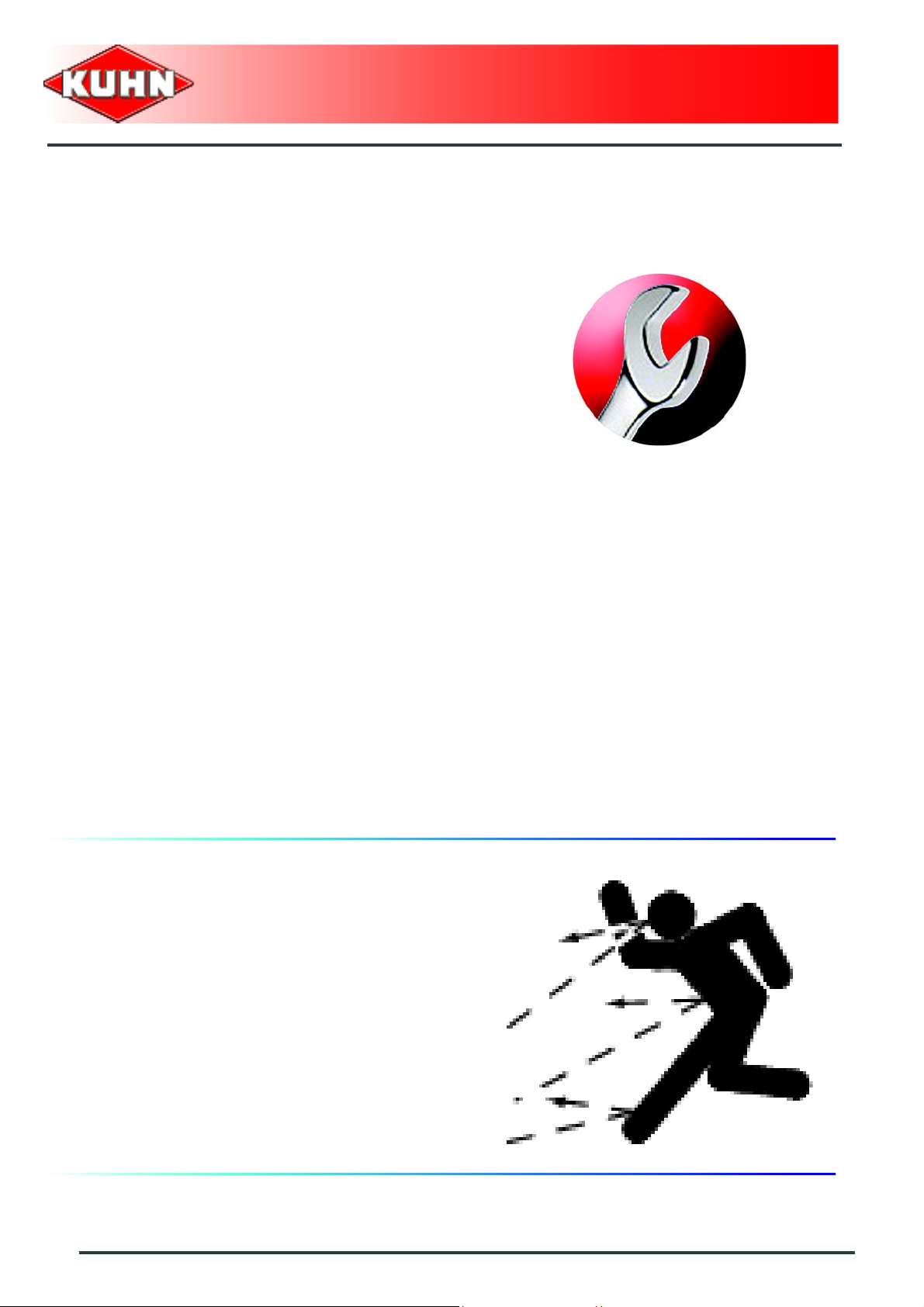
Projection of stones and foreign objects
For driver safety, always use a tractor equipped with a
cab. Never start the machine when there are people
nearby.
Even when the machine is used in accordance with its
purpose, objects may be projected. Stones and other
foreign objects projected by the moving parts can travel
a considerable distance. Keep all persons and animals
away from the danger zone.
16
Safety
Page 19

Precautions for machine use
Before using the machine, check tools (tines) and their
attachment hardware in accordance with the instructions
of the present manual.
Check the guards regularly. Immediately replace any
damaged or missing elements.
Before engaging the pto drive, lower the rotors onto the
ground. Make sure all the guards are in place. Keep all
persons and animals away from the danger zone.
Keep a safe distance from the Gyrotedder when the
rotors are in movement.
Never work in reverse.
After the power source has stopped, the rotors can
continue turning for a time. Stay away from the machine
until all moving parts have come to a complete standstill.
If an obstacle is hit, disengage the PTO drive, stop the
tractor engine, remove the ignition key and wait for all
moving parts to come to a complete standstill. Check the
entire machine for any damage before resuming work.
Gyrotedder
GF10802T
Safety
17
Page 20
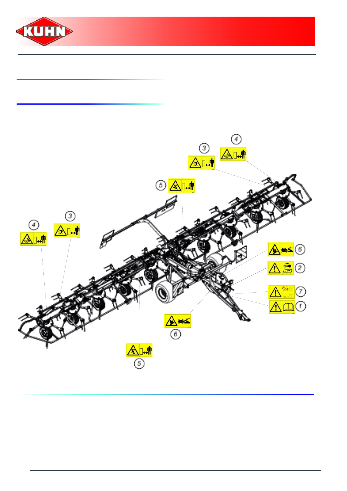
3. Location and description of safety decals on the machine
Location of safety decals
Gyrotedder
GF10802T
18
Safety
Page 21
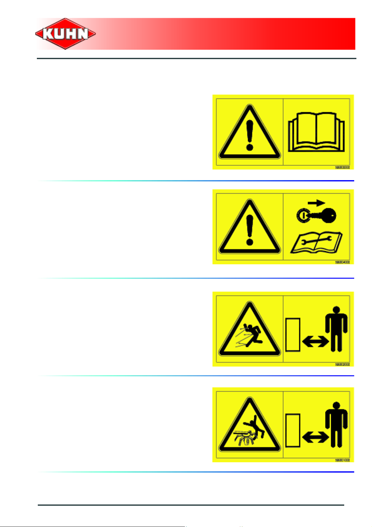
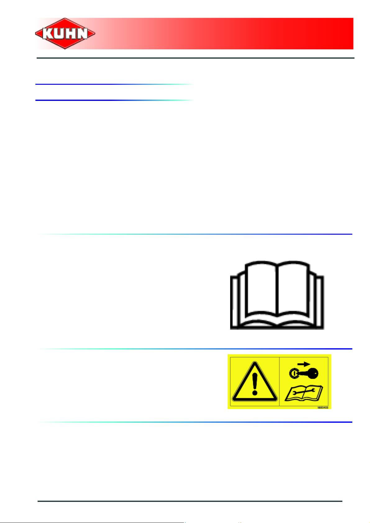
Description of safety decals
Operating instructions (1)
The operators' manual contains all the information
necessary for using the machine safely. It is imperative
to read and comply with all instructions.
Working on the machine (2)
Before leaving the tractor or before adjusting,
maintaining or repairing the machine, disengage the
PTO drive, turn off the engine, remove ignition key and
wait until all moving parts have come to a complete stop
and apply park brake.
Gyrotedder
GF10802T
Projections (3)
Stones and other debris projected by the moving parts
can travel a long distance. Always stay at a safe distance
from the machine.
Rotary tools (4)
To prevent entanglement keep a safe distance fro m the
machine.
Safety
19
Page 22
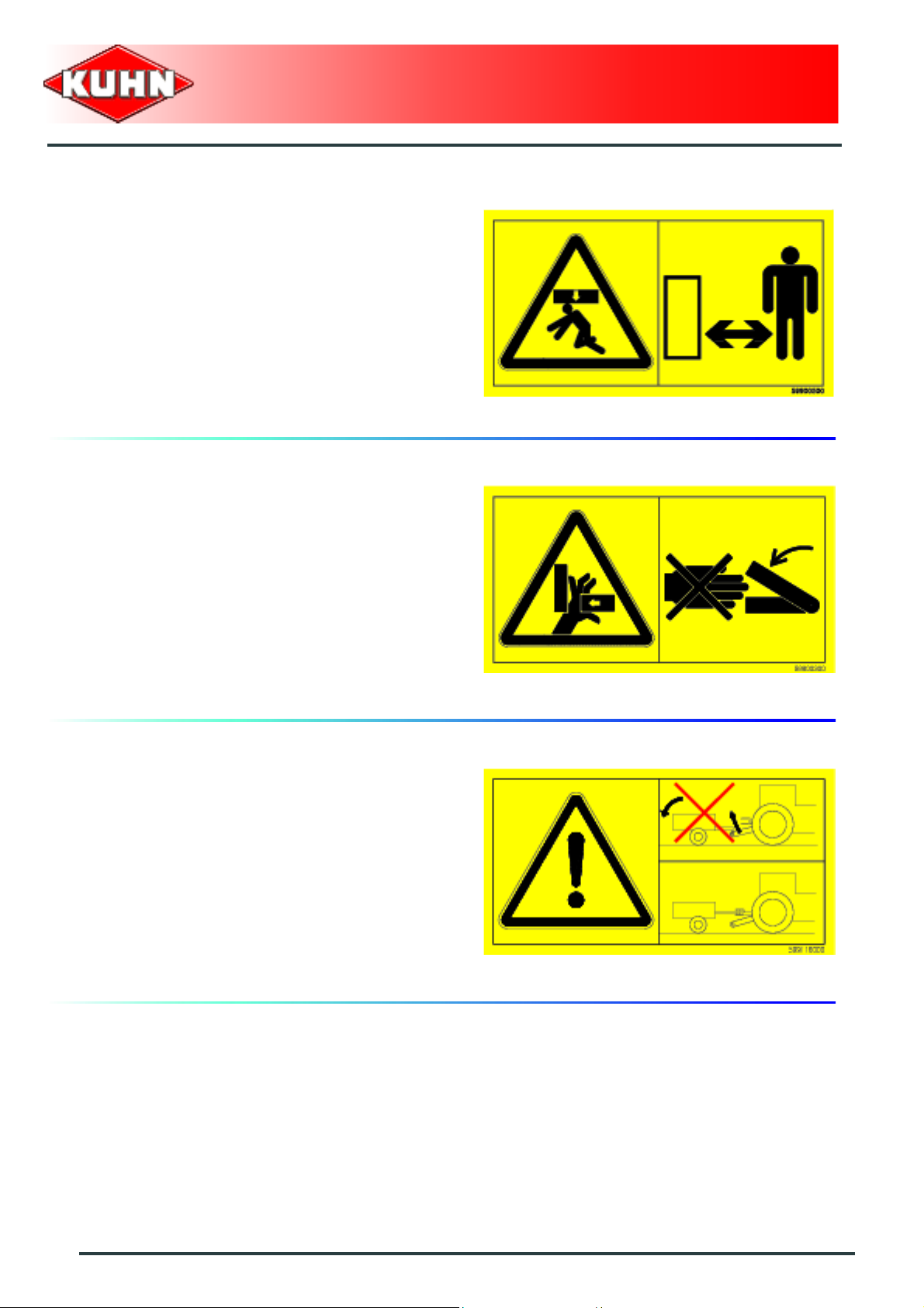
Body crushing (5)
Stay a safe distance from the machine. Crushing hazard.
Crushing area (6)
Never operate in an area where there is a crushing risk
before all moving parts have come to a complete stop.
Gyrotedder
GF10802T
Coupling device (7)
Never couple the machine to the multihole bar, there is a
risk of tipping over. Couple it to the pull bar.
20
Safety
Page 23

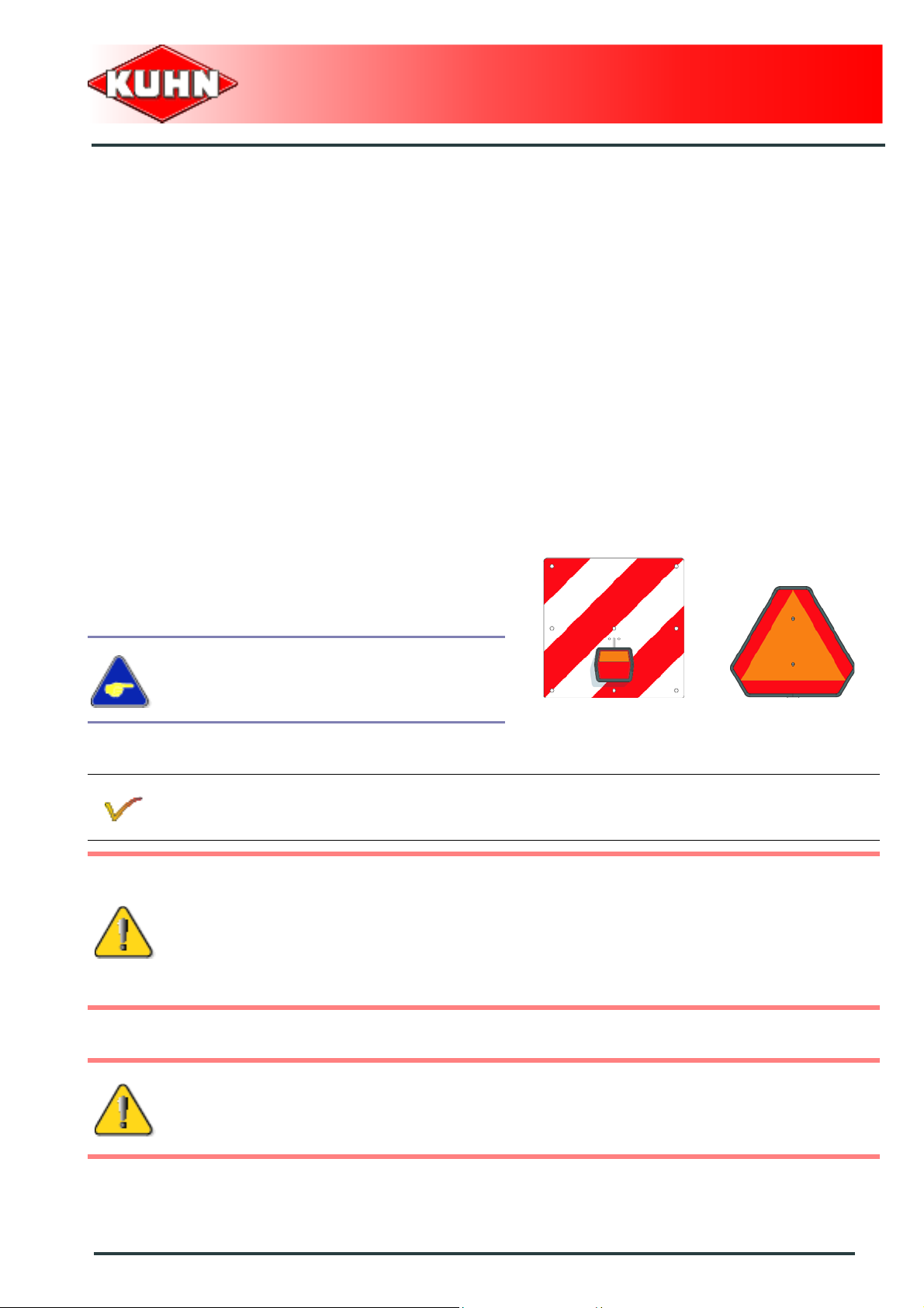
4. Road safety equipment and recommendations
The road safety equipment is mounted in the factory or
by your authorized Kuhn dealer according to current
safety regulations. Always keep to the legal speed limit
for driving a tractor-machine assembly on public roads .
Whatever the speed, we recommend, for everyones'
safety, not to exceed a maximum speed of
40 km/h (25 mph).
Gyrotedder
GF10802T
The front safety device comprises:
- 2 signalling panels (1).
- 2 white lights (2).
- 2 white reflectors (3).
The rear safety device comprises:
- 2 signalling panels (1).
- 2 signalling lights (2) (red light / stop light / turn signal
light).
- 4 red reflectors (3).
- 1 identification plate light (4).
- A speed limit decal (5) supplied according to the
country where the machine is bound for.
Safety
21
Page 24

The side device comprises:
- 6 self-adhesive amber reflectors (1) (3 on each
machine side).
Gyrotedder
GF10802T
Tyre pressure
- Transport wheels (1): 2.2 bar (32 psi).
- Central parts (2): 2.0 bar (29 psi).
- Outer wings (3): 1.5 bar (22 psi).
22
Safety
Page 25

$Machine specifications
1. Description and glossary
0
Gyrotedder
GF10802T
1 : Drawbar 2 : Coupling device
3 : Front parking stand 4 : Front guard
5 : Outer guard 6 : Outer wing folding cylinder
7 : Pitch angle adjustment handle 8 : Outer wing
9 : Drive shaft support 10 : Central gearbox
11 : Transport wheel 12 : Wheel chocks
13 : Rotor wheel
Machine specifications
23
Page 26

Gyrotedder
2. Technical specifications
GF10802T
Attachment type Drawbar coupled to the tractor hitch bar
Number of rotors 10
Number of tine arms per rotor 6
Working width (DIN 11220) 10.80 m (35’5’’)
Width in working position 11.20 m (36’9’’)
Length in working position 4.80 m (15’9’’)
Height in working position 2.05 m (6’8’’)
Width in transport position 2.99 m (9’10’’)
GF10802T
Length in transport position 4.60 m (15’1’’)
Height in transport position 3.30 m (10’10’’)
Minimum PTO power requirement 40 kW (55 hp)
PTO speed 540 min
Ground 1820 kg (4012 lb)
26x12.00-12 ( Tr an sp o rt wh ee ls)
Tyres
Tyre pressure
16x9.5-8 (Central parts)
16x6.5-8 (Outer wings)
2.2 bar (32 psi) (Transport wheels)
2.0 bar (29 psi) (Central parts)
1.5 bar (22 psi) (Outer wings)
-1
24
Machine specifications
Page 27

3. Required equipment
Coupling the machine
The country of destination determins the type of coupling
device supplied with the machine:
Kit no. 1126400: Attachment yoke diameter 40 mm
(1.6’’).
Gyrotedder
GF10802T
Kit no. 1126410: Ball hitch drawbar diameter 80 mm
(3.1’’).
Kit no. 1126420: Coupling device (US - CA).
Kit no. 1126430: Coupling device (IT).
Machine specifications
25
Page 28

4. Sound levels
Sound levels have been measured in accordance with the measuring methods as defined in:
NF EN ISO 4254-1.
«Agricultural machinery - Safety - Part 1: General requirements».
Weighted equivalent continuous acoustic pressure level at the driver's seat (closed cabin) L (A) eq:
Tractor only: 78.7 dB(A).
Tractor + machine: 77. dB(A).
Gyrotedder
GF10802T
26
Machine specifications
Page 29

$Putting into service
1. Description of control elements
The machine is equipped with:
- A release cord to control the m achine transport/work
position setting.
- 2 hydraulic hoses that control the transport/work
position setting of the transport wheels and the folding
of the outer wings.
- 2 hydraulic hoses that control the oblique position
setting cylinder.
- 1 handle to adjust the pitch angle.
- An electric 7-pin plug for the signalling equipment.
Gyrotedder
GF10802T
The machine is supplied with an 12 Allen key (Separate
packet).
Putting into service
27
Page 30

2. Coupling and uncoupling
Description of coupling elements
The machine is equipped with:
- A PTO shaft 1 3/8’’ - 6 splines (1).
- 4 hydraulic hoses (3).
- A 7-pin plug (2).
Gyrotedder
GF10802T
Preparing the tractor
The machine adapts to tractors fitted with a hitc h ba r.
The tractor nominal PTO speed must be 540 min
The tractor must be equipped with:
- 2 double-acting hydraulic valves.
-1
.
28
Putting into service
Page 31

Coupling the machine
Depending on the type of coupling device
supplied with the machine, the procedure may
be slightly different.
- Couple machine to tractor and secure hitc h pin .
Gyrotedder
GF10802T
- Raise parking stand (1) using crank (2).
Putting into service
29
Page 32

- Remove specific pin (1) (Pin with automatic locking
mechanism).
- Retract parking stand.
- Lock parking stand using specific pin (1).
- Place release cord handle in the tractor cab.
Gyrotedder
GF10802T
Safety chain
The machine is supplied with a ANSI/ASAE safety chain
type with a minimum ultimate system strength of
45 kN (10100 lbf).
The safety chain is intended to keep the
machine under control in the event of a loss
or failure of the hitch pin.
The safety chain must be tied around a tractor
attachment point other than the attachment bar.
30
Putting into service
Page 33

Hydraulic connections
The tractor must be equipped with 2 double acting
valves.
Connect the 2 hydraulic hoses that control the machine
transport/work position setting to the same tractor
double acting valve.
Connect the 2 hydraulic hoses that con trol the oblique
position setting cylinder to the same tractor hydraulic
double acting valve.
Gyrotedder
GF10802T
Electrical connection
Connect 7-pin plug to the tractor.
Putting into service
31
Page 34

Intermediate PTO shaft 1
Make sure that the PTO shaft is correctly
adjusted, to avoid premature wear and tear.
The direction of rotation is shown on a decal.
Separate the two half PTO shafts and connect them to
the machine's input shaft and to the tractor PTO stub.
Check the length of the PTO shaft:
- Check the maximum overlap when the machine is in
work position and the tractor turned to the direction
which provides maximum overlap.
- When the PTO shaft is in its maximum extended
position, the tube overlap must be more than
250 mm (10’’).
- When the PTO shaft is in its maximum overlap
position (retracted), tubes should not butt against the
yokes. As a safety measure, a clearance (L) of at least
25 mm (1’’) must be maintained.
Gyrotedder
GF10802T
If this is not the case:
• Mark length (H) to cut when the transmission is the
maximum overlap position.
• Shorten the guard tubes and the tran smission tubes
by the same length.
• Bevel and clean the tubes.
• Grease the inside of the outer tube.
Check that there is still a minimum overlap of
250 mm (10’’) when the machine is in working
position and the tractor in line with the machine.
Never operate the PTO shaft at an angle X exceeding
30°.
32
Putting into service
Page 35

To avoid serious accidents, the PTO drive
shaft guards must be properly in place and
fixed with the chains provided.
On machine side, attach pto guard chain around the
hose passing hole (1).
Immediately replace any worn or damaged
guard.
Gyrotedder
GF10802T
Lower PTO shaft support.
Putting into service
33
Page 36

Uncoupling the machine
Park the machine on an even fairly level
ground.
From the transport position:
- Block machine with wheel chocks (1).
Gyrotedder
GF10802T
- Remove specific pin (1).
- Lower parking stand.
- Lock parking stand using specific pin (1).
- Adjust parking stand height using crank handle.
- Raise PTO shaft support (1).
- Uncouple and place PTO shaft in support (1).
34
Putting into service
Page 37

- Disconnect and store hydraulic hoses on holder (1).
- Remove cord from tractor an d store it in its holde r on
the machine.
- Disconnect and store signalling plug on holder (1).
Gyrotedder
GF10802T
- Remove and store safety chain on the drawbar.
- Remove hitch pin.
- Move forward with the tractor.
The machine is uncoupled.
The machine must be parked in working
position if ground is not level.
Putting into service
35
Page 38

$Instructions for transport
Before placing the machine into transport
position:
- Disengage tractor PTO.
- Wait until the rotating parts have come
to a complete stop.
- Check that nobody is within the machine
pivoting area.
- If there is someone, make sure the
person moves away.
Gyrotedder
GF10802T
1. Putting the machine into transport position
From the working position:
- Pull cord linked to the hydraulic valve (1).
- Shift transport/work cylinder control valve in the "pivot
into transport" position until transport wheels touch
the ground and slightly offload the wheels of the
central rotors.
- Release cord.
- Operate transport/work cylinders in the transport
position direction until cylinders reach travel end:
• The wings will lift further than headland turn position
(a) and (b).
36
Instructions for transport
Page 39

- Pull cord linked to the hydraulic valve (1):
• The machine is raised (a) and tips forwards (b).
- Wait until cylinders reach end of stroke.
- Release cord.
Gyrotedder
GF10802T
The machine is in transport position.
Never engage the tractor PTO drive when t he
machine is in transport position.
Instructions for transport
37
Page 40

2. Conformity with the road regulations
Before driving the machine on public roads,
ensure that the machine complies with
current highway code regulations.
Never tow the machine at a speed exceeding
40 km/h (25 mph).
Instructions specific to France:
Never tow the machine at a speed exceeding
25 km/h (15,5 mph).
Gyrotedder
GF10802T
- Check that reflectors are clean.
Check that transport locks (1) are fully
engaged.
Regularly check the tyre pressure.
Make sure the release cord cannot be
operated inadvertently.
38
Instructions for transport
Page 41

$Instructions for work
Before placing the machine in working
position:
- Check that nobody is within the machine
pivoting area.
- If there is someone, make sure the
person moves away.
1. Putting the machine into work position
Gyrotedder
GF10802T
From the transport position:
- Pull cord linked to the hydraulic valve (1).
- Shift the transport/work c ylinder control valve in the
work position direction until the central rotor wheels
slightly touch the ground:
• The machine is lowered on the ground (a) and tips
rearwards (b).
- Release cord.
Instructions for work
39
Page 42

- Operate transport/work cylinders in the work position
direction until cylinders reach travel end:
• The outer wings unfold until they come into contact
with the ground (a) and (b).
Gyrotedder
GF10802T
- Pull cord linked to the hydraulic valve (1).
- Operate transport/work cylinder in the work position
direction until cylinder reaches travel end:
• The transport undercarriage folds underneath the
chassis.
• The sections are in working position.
The machine is in working position.
If equipped, shift tractor valve in the detented
float position.
40
Instructions for work
Page 43

2. Adjustments in working position
Before carrying out any maintenance or
repairs on the machine, switch off the tractor
engine, remove ignition key, wait until all
moving parts have come to a standstill and
apply park brake.
Pitch angle adjustment
Adjust to maximum pitch angle in large crop
quantities.
Adjust to minimum pitch angle in small crop
quantities.
Gyrotedder
GF10802T
Slightly lift the machine from the ground.
- Rotate lever by a 1/4 turn to unlock adjustment system
(1).
- Lift crank (2) to obtain maximum pitch angle (a).
- Lower crank (2) to obtain minimum pitch angle (b).
- Rotate lever by a 1/4 tu rn to lock adjustment s ystem
(1).
Proceed same way on each rotor.
- Lower machine back on ground.
- Adjust machine pitch angle with handle (1).
The distance between tines and soil is a very
important factor with regards to the machine
work quality and tine service life.
Instructions for work
41
Page 44

Work in oblique position
The oblique position can be used when tedding on field
edges.
From the working position:
- Operate hydraulic oblique position cylinder (1) to pivot
rotor wheels in the required direction.
Gyrotedder
GF10802T
42
Instructions for work
Page 45

3. Machine use
Groundspeed
The following factors determine the forward speed:
- The humidity level (This factor is particularly
determining when wilting).
- The crop density.
- The crop composition (blade length).
- The ground contours.
General advice:
In dense and average length crop:
- When wilting a crop with high humidity level.
• the speed is approximately of 7 to 8 km/h (4.4 -
5 mph).
- When tedding a more or less dry crop.
• the speed is approximately of 10 to 12 km/h (6.3 -
7.5 mph).
• The dryer the crop, the more the PTO speed must
be reduced.
• For a very dense, humid crop composed of very
long blades, the forward speed must be reduced.
Gyrotedder
GF10802T
For difficult working conditions, it is
recommended to operate at a lower forward
speed.
Driving the machine
When turning while tedding on field edges,
the turning angle must not exceed 60° with
regards to the direction of travel.
Instructions for work
43
Page 46

Adaptation to the ground irregularities
Transport wheels
The use of transport wheels improves the ground
countour adaptation.
Adjustments for work
This configuration does not allow work in oblique
position.
From the working position:
- Shift transport/work cylinder control valve in the "pivot
into transport" position until transport wheels touch
the ground and slightly offload the wheels of the
central rotors.
- Remove lynch pin (3).
- Remove drawbar lock pin (1) and position it in hole ( 2).
Gyrotedder
GF10802T
Turn pitch angle adjustment handle in one or th e
other direction to free the lock pin.
- Insert and lock lynch pin (3).
Activate transport/work position cylinder in one
or the other direction to adjust the front
tines/ground distance if necessary.
Transport adjustment
- Remove lynch pin (3).
- Remove drawbar lock pin (1) and position it in hole ( 4).
Turn pitch angle adjustment handle in one or th e
other direction to position holes in line.
- Insert and lock lynch pin (3).
- Shift the transport/work cylinder control valve in the
"pivot into work" position to raise the transport wheels
at the maximum.
Putting the machine into transport position:
- See chapter: ’’Instructions for transport’’.
44
Instructions for work
Page 47

1. Spare wheel
Kit no. 1126330
Dimensions: 16 x 6.5 - 8 (6 PLY)
Tire pressure: 1.5 bar (22 psi).
Gyrotedder
GF10802T
$Optional equipment
2. DUPLEX gearbox
Kit no. 1126540
The DUPLEX gearbox enables forming night windrows
by reducing the rotor rotation speed or maintaining the
high rotation speeds necessary for tedding.
Machine use
To tedd:
- Connect PTO shaft to the central gearbox input shaft.
- Fit PTO cover inside the guard to protect the non used
pto stub.
Optional equipment
45
Page 48

For forming night windrows:
- Connect PTO shaft to the DUPLEX gearbox input
shaft.
- Fit PTO cover inside the guard to protect the non used
pto stub.
Gyrotedder
GF10802T
3. Double prop wheels
Kit no. 1126550
This equipment enables machine adaptation to ground
contours.
The double prop wheels are moun ted on the right and
left side of the front beam.
Machine use
Putting the machine into work position
- Place the machine in working position.
- Lower the prop wheels using cranks (1) until they are
in contact with the ground.
- Remove lynch pin (2).
- Remove drawbar lock pin (3) and position it in hole ( 4).
- Insert roll pin (2) to secure pin.
- Rotate crank a few additional times to allow the prop
wheel to stay continuously in contact with the ground:
• Repeat procedure on the other wheel if necessary.
46
Optional equipment
Page 49

Putting the machine into transport position
From the working position:
- Remove lynch pin (2).
- Insert drawbar lock pin (3) in hole (4).
- Insert roll pin (2) to secure pin.
- Raise the prop wheels using cranks (1).
Lubrication
Gyrotedder
GF10802T
Every 50 hours
Grease:
- Pivot points (1).
Optional equipment
47
Page 50

1. Frequency chart
Maintenance intervals are indicated for
normal conditions of use.
Gyrotedder
GF10802T
$Maintenance and storage
Lubrication
Grease:
- The outer wing pivot pins
- The <DIGIDRIVE> coupling fingers
- The pitch angle adjustment handle
- The transport carriage
Oil:
- The outer wing hydraulic cylinder pivot pins
- Pitch angle adjustment pivot points
Maintenance
Check:
- Tightness of all bolts and nuts
- The central gearbox oil level
After the first
10 hours of
use
Once per week
Every 50 hours
or at the end of
the season
3
3
33
3
48
Maintenance and storage
Page 51

2. Lubrication
Before carrying out any maintenance or
repairs on the machine, switch off the tractor
engine, remove ignition key, wait until all
moving parts have come to a standstill and
apply park brake.
The pictorials show the points to be greased (Part
no. 09905400).
Clean grease nipples before greasing.
Gyrotedder
GF10802T
Lubricate with SHELL multi-purpose grease
grade NLGI 2.
Maintenance and storage
49
Page 52

Lubrication
Intermediate PTO shaft 1
Lubricate the central disc of each universal
joint with PTO shaft positioned so that it is
straight.
- Every 20 hours:
• U-joints (1).
• Transmission tube (2).
- Every 100 hours:
• Guide rings (3).
Gyrotedder
GF10802T
Intermediate PTO shaft 2
- Every 20 hours:
• U-joints (1).
• Transmission tube (2).
- Every 100 hours:
• Guide rings (3).
50
Maintenance and storage
Page 53

Grease
- The outer wing pivot pins.
Gyrotedder
GF10802T
Maintenance and storage
51
Page 54

- The <DIGIDRIVE> coupling fingers.
Gyrotedder
GF10802T
52
Maintenance and storage
Page 55

- Link rods.
Gyrotedder
GF10802T
Maintenance and storage
53
Page 56

- The pitch angle adjustment handle.
Gyrotedder
GF10802T
- The transport carriage.
54
Maintenance and storage
Page 57

Oil
Oil with SHELL SAE 90 gear oil.
- Cylinder pivot points (1).
- Pitch angle adjustment pivot points (2).
Gyrotedder
GF10802T
Maintenance and storage
55
Page 58

3. Maintenance
Central gearbox oil level control
The main gearbox is lubricated with
0.7 L (0.18 US gal) of SHELL SPIRAX A
extreme-pressure gear oil with viscosity grade
SAE 80W90 and API grade GL5.
Gyrotedder
GF10802T
Check the oil level in the tank periodically:
- Remove level plug (1).
• The oil level must reach lower part of level plug hole.
- Top up if necessary.
- Clean and reinstall filler plug (1) and its washer.
Replace if necessary.
Checking the fixing elements
Check that all nuts and bolts are sufficiently tightened.
56
Maintenance and storage
Page 59

Replacing a tine
Before leaving the tractor or before
adjusting, maintaining or repairing the
machine, disengage the PTO drive, turn off
the engine, remove ignition key and wait until
all moving parts have come to a complete
stop and apply park brake.
2 types of tines are fitted on the machine:
- Tines (1) for rotors rotating clockwise
- Tines (2) for rotors rotating
Check that the tines are f itted properly with
regards to the rotor direction of rotation.
Gyrotedder
GF10802T
(a).
counterclockwise (b).
Maintenance and storage
57
Page 60

From the working position:
- Remove attachment screw (1) using key supplied
(Separate packet).
Respect mounting instructions so that the crop's
pressure (a) closes the coils.
Gyrotedder
GF10802T
- Replace tine.
Check attachment bolt, washer and nut. Replace
if necessary.
- Reassemble the unit.
Check that the tine is properly embedded in
the tine arm.
- Tighten attachment screw:
• Torque: 18 daN m (133,2 lbf ft).
58
Maintenance and storage
Page 61

Tyre pressure
- Transport wheels (1): 2.2 bar (32 psi).
- Central parts (2): 2.0 bar (29 psi).
- Outer wings (3): 1.5 bar (22 psi).
Gyrotedder
GF10802T
4. Storage
At the end of each season:
- Clean the machine thoroughly.
- Lubricate the whole machine.
- Check tyre pressure:
•
Transport wheels
• Central parts: 2.0 bar (29 psi).
• Outer wings: 1.5 bar (22 psi).
- Touch up any areas of damaged paintwork.
- Check and replace worn or damaged tines.
- Put the machine under cover in a dry place.
At the start of each season:
- Re-read the operators' manual.
- Check tyre pressure:
•
Transport wheels
• Central parts: 2.0 bar (29 psi).
• Outer wings: 1.5 bar (22 psi).
- Check that all nuts and bolts are sufficiently tightened.
- Make sure that all protection devices are in place and
in good condition.
: 2.2 bar (32 psi).
: 2.2 bar (32 psi).
Maintenance and storage
59
Page 62

$Appendix
1. Calculating the load on an axle
When coupling a tool to the front and rear 3-point lift linkage, the maximum authorized payload must
not be exceeded.
The load on the tractor front axle must always represent 20 % of the tractor unladen weight.
Prior to use, check that these conditions ar e satisfied by making this calculation or by weighing the
tractor-machine unit
Define the total weight, axle loads, tyre
capacity and minimum additional mass:
Gyrotedder
GF10802T
The following values are required for the calculation:
Description Units Description
T kg Tractor unladen weight
T1 kg Unladen load on tractor front axle
T2 kg Empty load on tractor rear axle
t kg Axle loads (Tractor + machine)
t1 kg Load on front axle (Tractor + machine)
t2 kg Load on rear axle (Tractor + machine)
M1 kg Total weight of front tool or front ballast
M2 kg Total weight of rear tool or rear ballast
am
b m Distance between the tractor axles
cm
d m
Distance between the tools' centre of gravity or the front ballast and
the front axle centre
Distance between the rear axle center and the center of the lower link
ball joints
Distance between the centre of the lower link ball joints and the centre
of gravity of the rear tool or rear ballast
Obtaine
d by
60
Refer to the tractor operators' manual Refer to the machine price-list or operators' manual
Dimensions Measure on scale
Appendix
Page 63

Rear tool or front-rear combination:
Gyrotedder
GF10802T
1) Calculation of the minimum front ballast weight M1
minimum
M2 x (c+d) - T1 x b + 0.2 x T x b
M1
minimum
=
a+b
Write the minimal additional weight in the chart.
Front tool:
2) Calculation of the minimum rear ballast weight M2
minimum
M1 x a - T2 x b + 0.45 x T x b
M2
minimum
=
b+c+d
Write the minimal additional weight in the chart.
3) Calculation of the actual load on the front axle T1
If the front tool (M1) is lighter than the minimum load required at the front (minimum), increase tool weight until the required minimum
front load is reached
real
M1 x (a+b) + T1 x b - M2 x (c+d)
T1
=
real
b
Indicate front axle calculated load value and the one indicated in the tractor operators' manual.
4) Calculation of the total weight M
If the rear tool (M2) is lighter than the minimum load required at the rear(minimum), increase tool weight until the required minimum
rear load is reached
real
M
= M1 + T + M2
real
Indicate calculated total load value and the one autho rized as indicated in the tractor operator's manual.
5) Calculation of the actual rear axle load T2
T2
= M
real
real
real
- T1
real
Indicate rear axle calculated load value and the one indicated in the tractor operator's manual.
6) Tyre carrying capacity
Indicate double (2 tyres) the authorized load value (see tyre manufacturer indications).
Appendix
61
Page 64

Table:
Gyrotedder
GF10802T
Actual value obtained
by calculation
Minimum front/rear
ballasting
Total weight kg ≤ kg
Load on front axle kg ≤ kg ≤ kg
Load on rear axle kg ≤ kg ≤ kg
The minimum ballasting must be made by fitting a tool or an additional mass to the
tractor.
The values obtained must be below or equal the authorized values.
kg
Value authorized
according to
operator's manual
Double value of the
authorized capacity
per tyre (2 tyres)
62
Appendix
Page 65

Determining the machine weight (M2) and the position of its centre of gravity (d)
If the data required to calculate the total
weight, axle loads and minimum ballasting
are not supplied, use the following method.
Tractor only:
Gyrotedder
GF10802T
- T1: Load on front axle.
•Tractor only.
- T2: Load on rear axle.
•Tractor only.
Appendix
63
Page 66

- T: Axle loads.
• Tractor only.
Gyrotedder
GF10802T
64
Appendix
Page 67

Gyrotedder
GF10802T
Rear tool or front-rear combination:
If the total unit weight exceeds the tractor Gross Combined We ight Rating in accordance wit h the
countrie's legislation, empty the hopper to travel on public roads.
In any case, we recommend to travel on public roads with empty hoppers and tanks.
- Measure dimension (b).
- Measure dimension (c).
- t1: Load on front axle.
• Tractor + machine.
• Hopper empty.
- t: Axle loads.
• Tractor + machine.
• Hopper empty.
Calculating the rear tool weight (M2):
M2 = T - t
Calculating the distance (d):
d = (( b x ( T1 - t1) ) / M2 ) - c
Appendix
65
Page 68

$Limited warranty
Gyrotedder
GF10802T
66
Limited warranty
Page 69

Gyrotedder
GF10802T
Limited warranty
67
Page 70

Page 71

Page 72

 Loading...