

Page 1
ASSEMBLY / OPERATOR'S MANUAL
GA 8001 H GYRORAKE
N° 95318 C.GB - 06.1999
Page 2
DEAR OWNER,
In buying a KUHN machine you have chosen wisely. Into it have gone years of thought,
research and improvements. You will find, as have thousands of owners all over the world, that
you have the best that engineering skill and actual field testing can produce. You have
purchased a dependable machine, but only by proper care and operation can you expect to
receive the performance and long service built into it.
This manual contains all the necessary information for you to receive full efficiency from your
machine. The performance you get from this machine is largely dependant upon how well you
read and understand this manual and apply this knowledge. Please DO NOT ASSUME THAT
YOU KNOW HOW TO OPERATE AND MAINTAIN YOUR MACHINE before reading this
manual carefully. KEEP THIS MANUAL AVAILABLE FOR REFERENCE.
Your KUHN dealer will instruct you on the general operation of your machine. He is interested
that you get the best performance possible and will be glad to answer any special questions
that may arise regarding the operation of the KUHN machine.
Your KUHN dealer can offer a complete line of genuine KUHN service parts.
These parts are manufactured and carefully inspected in the same factory that builds the
machine to assure high quality and accurate fitting of any necessary replacements.
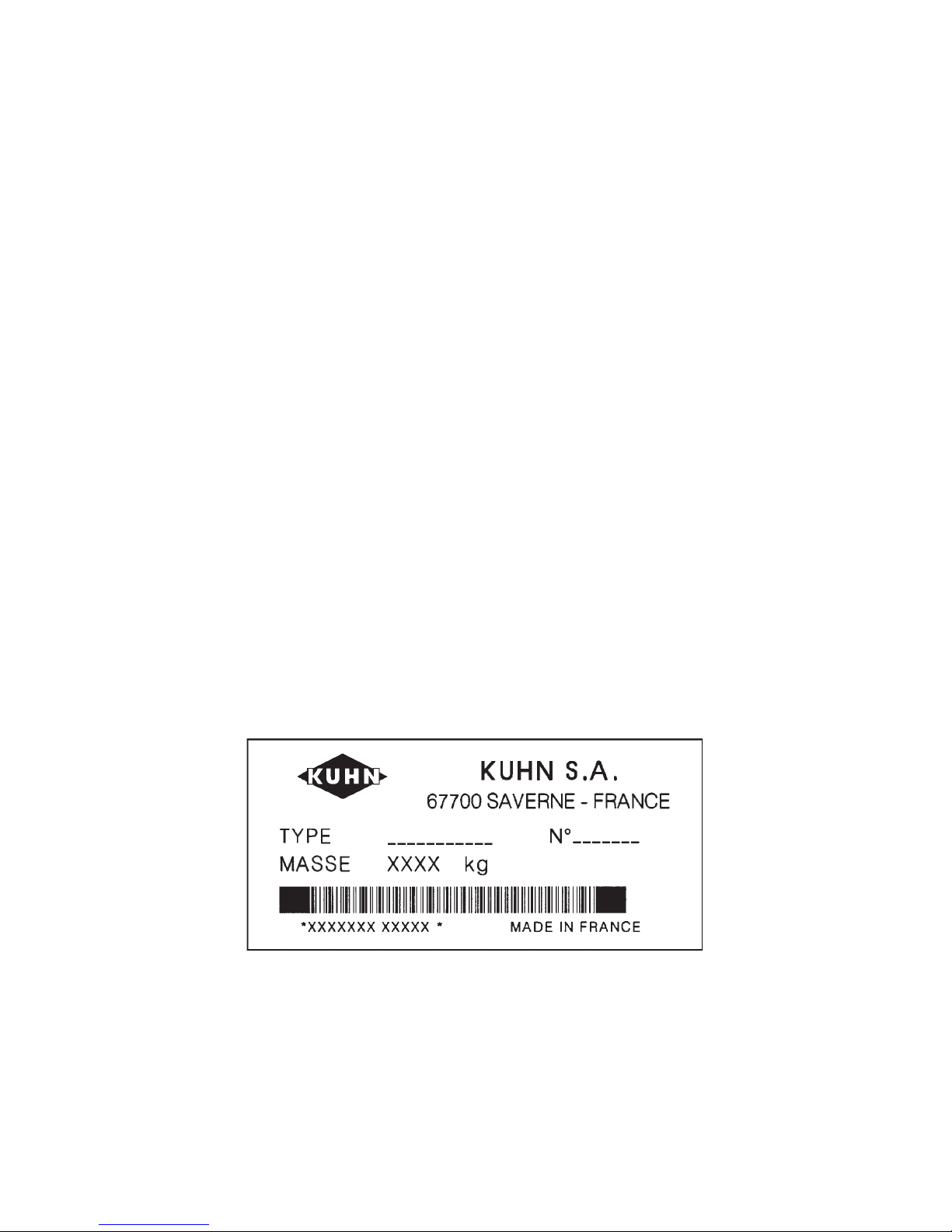
When ordering service parts it is important that you indicate the type of machine concerned
and its serial number.
For this reason please complete the model identification plate diagram below with the required
information. This will provide you with an easy reference for future service parts orders.
ABOUT IMPROVEMENTS
KUHN is continually striving to improve its products and, therefore, reserves the right to make
improvements or changes when it becomes practical to do so, without incurring any
obligations to make changes or additions to the equipment sold previously.
Page 3

- 1 -
CONTENTS
Safety 2
Safety decals 8
Technical specifications 11
Assembly instructions 12
Attachment : - Fitting to the tractor 28
- PTO transmission shaft 30
Work position and adjustments 32
Operation 34
Forward speed 34
Transport 36
Parking the machine 38
Lubrication 40
Optional accessories 42
Electrical connector (for North America) 44
Conditions of limited warranty 45
Copyright 1999 KUHN S.A.
Page 4

- 2 -
SAFETY
The above symbol is used throughout this manual every time recommendations are made concerning your
safety, the safety of others, or the good operation of the machine.
These recommendations must be made known to all machine operators.
DESIGNATED USE OF THE MACHINE
The GA 8001 H Gyrorake must only be used for the work for which it has been designed : raking on the ground
and forming swaths of pre-mowed fodder and straw.
The manufacturer is not held liable for any damage resulting from machine applications other than those
specified by the manufacturer.
Any use other than the designated operation is at the risk and responsibility of the operator.
Designated use of the machine also means :
- following operation, maintenance and repair recommendations given by the manufacturer ;
- using only genuine spare parts, equipment and accessories as designated by the manufacturer.
The GA 8001 H Gyrorake must only be operated, maintained and repaired by competent persons who are familiar
with machine specifications and operation and are aware of any danger involved.
The operator must imperatively respect current legislation concerning :
- accident prevention,
- work safety,
- public traffic circulation.
All safety advice indicated on the machine must be strictly observed.
The manufacturer is not held liable for any damage resulting from machine modifications carried out by the
operator himself or by a third party without previous written agreement from the manufacturer.
Page 5

- 3 -
GENERAL SAFETY RECOMMENDATIONS
Before operating the machine, always ensure that tractor and machine are in accordance with work safety and
road traffic regulations.
BASIC PRINCIPLES
1. In addition to the recommendations given in this manual, legislation on work safety and accident prevention
must also be respected.
2. Advice is indicated on the machine, specifying safety recommendations in order to prevent accidents.
3. Before travelling on public roads, the operator must ensure that the machine conforms to road traffic
regulations.
4. Before starting work, the operator must be familiar with all machine controls, handling devices and their
functions. Once at work, it is too late to do this !
5. Do not wear loose clothing which could become caught up in moving elements.
6. Use a tractor equipped with a safety cab. Keep windows and roof hatch closed for reduced sound level while
operating the PTO drive implement.
7. Before starting up the machine and beginning work, check the surrounding area (beware of children !). Make
sure there is sufficient visibility.
Keep all people and animals away from the danger zone of the machine (risk of projection !)
8. Carrying people or animals on the machine when working or in transport is strictly forbidden.
9. Machine must only be attached to tractor using means provided and in accordance with current safety
standards.
10. When attaching or removing the machine, place the parking stand into the corresponding position.
11. Special care should be taken when attaching or removing the machine from the tractor.
12. Before attaching the machine, ensure that the front tractor axle is sufficiently ballasted.
Ballast is to be placed on the supports provided in accordance with instructions of the tractor manufacturer.
13. Do not exceed the maximum axle load or the overall transport weight as prescribed by the tractor
manufacturer.
Page 6

- 4 -
14. Do not exceed the maximum transport width authorized by road traffic regulations.
15. Before travelling on public roads, ensure that all legally required guards and indicators (lights, reflectors ...)
are in place and in good operation.
16. All operating controls (cords, cables, rods...) must be positioned so that they cannot be set off accidently,
risking accident or damage.
17. Before traveling on public roads, put the machine into its transport position as instructed in this operators
manual.
18. Never leave the tractor seat while the machine is operating.
19. Drive speed must be adapted to ground conditions as well as to roads and paths.
Always avoid abrupt changes of direction.
20. Precision steering, tractor adherence, road holding and efficient braking are influenced by the type of
implement, weight, ballast of front axle, ground or road conditions. It is therefore of utmost importance to
be cautious in every given situation.
21. Be particularly cautious when turning corners, paying attention to machine overhang, length, height and
weight.
22. Before operating the machine, ensure that all safety guards are firmly in place and in good condition. If worn
or damaged, replace immediately.
23. Before operating the machine, check the tightness of all nuts and bolts, particularly on fixing elements
(blades, tines, knives, spades ...)
24. Keep clear of the machine operating area.
25. WARNING ! Danger of crushing and shearing can exist when components are operated by hydraulic or
pneumatic controls.
26. Before leaving the tractor or before adjusting, maintaining or repairing the machine, turn off the engine,
remove the ignition key and wait until all moving parts have come to a complete stop.
27. Do not stand between the tractor and the machine unless the hand brake is tight and/or stops have been
placed under the wheels.
28. Before any adjustments, maintenance or repairs are carried out, ensure that the machine cannot be started
up accidentally.
Page 7

- 5 -
ATTACHMENT
1. When attaching or removing the machine from the tractor, make sure that it cannot move accidentally.
(Put wedges under the wheels).
2. When attaching the machine to the tractor hydraulic linkage, ensure that diameter of the link pins corresponds
to the diameter of the ball joints.
3. WARNING ! Danger of crushing and shearing can exist in the lifting zone of the tractor hydraulic linkage !
4. Do not stand between the tractor and the machine when operating the outer control lever of the lift mechanism.
5. Make sure that the weight applied to the tractor's draught arms does not go over the maximum weight
indicated by the manufacturer.
6. Make sure flexibility between tractor draught arms and machine drawbar is sufficient.
7. In transport, the tractor draught arms should be stabilized by the linkage to avoid stabilizer bars side to side
shifting.
8. Never operate or transport the machine on sloping or bumpy fields with a narrow wheel track tractor.
POWER TAKE-OFF
1. Use only the PTO shaft supplied with the machine or recommended by the manufacturer.
2. PTO guards must always be in place and in good condition.
3. Check for correct PTO overlap when at work and in transport.
4. Before attaching or removing the PTO shaft, disengage PTO shaft, turn off engine and remove ignition key.
5. If a primary PTO shaft is equipped with a slip clutch or a free wheel, these must be fitted on the machine PTO.
6. Ensure that PTO shaft is always correctly fitted and locked into place.
7. Make sure guards are correctly in place and secured with the safety chains provided.
8. Before engaging PTO, ensure that PTO speed (rotational frequency) and direction are in accordance with
manufacturers recommendations.
9. Before engaging PTO, keep all people and animals clear from the machine.
Page 8

- 6 -
10. Never engage PTO shaft when tractor engine is turned off.
11. Never surpass the PTO angle recommended by the manufacturer.
12. WARNING ! Rotating elements can continue turning momentarily after PTO is disengaged. Keep clear until
all rotating elements are at a standstill.
13. When removing the machine, place PTO shaft on the supports provided.
14. Fit the safety cap on tractor PTO.
15. Replace any worn or damaged PTO guards immediately.
HYDRAULIC SYSTEM
1. Beware ! The hydraulic circuit is under pressure (maximum working pressure : 200 bars/2900 psi).
2. When fitting hydraulic motors or cylinders, ensure that connections have been made correctly, as per
manufacturers instructions.
3. Before connecting hoses to the tractor hydraulics, ensure that tractor and machine circuits are not under
pressure.
4. It is strongly recommended that the operator marks the hydraulic connections between tractor and machine
to avoid making a wrong connection. WARNING ! Functions could be reversed (for example : lift/lower).
5. Regularly check the hydraulic hoses ! Replace the hydraulic hoses every 5 years. Damaged or worn hoses
must immediately be replaced .
When replacing the hydraulic hoses, make sure to use hoses with the specifications and quality recommended
by the manufacturer of the machine.
6. Should a leak be found, take all necessary precautions to avoid accidents.
7. Any liquid under pressure (particularly oil from hydraulics) can penetrate the skin and cause severe injury. If
injured, see a doctor immediately, there could be danger of infection.
8. Before any adjustments, maintenance or repairs are carried out, lower the machine, depressurize the circuit,
turn off the engine and remove ignition key.
Rotation speed ... rpm (American Measure) is also expressed in metric measure : Rotational frequency ... min
-1
.
Both units are equivalent, for example : Rotation speed 540 rpm equals Rotational frequency 540 min-1.
Page 9

- 7 -
TIRES
1. Before any work is performed on the wheels, ensure that the machine rests on the ground and is perfectly stable
so that it cannot move accidentally (put wedges in place).
2. Assembly, disassembly and repair of wheels and tires must only be carried out by competent persons who
are equipped with standardized tools.
3. Check tire pressure regularly !
Respect manufacturers recommendations on tire pressure.
MAINTENANCE
1. Before checking for any machine malfunction and before adjusting, maintaining or repairing the machine,
disengage PTO, turn off engine and remove ignition key.
2. Check tightness of nuts and bolts regularly. Retighten if necessary.
3. If the machine is raised, prop it up in a stable position before carrying out any maintenance work.
4. When replacing a working part, wear protection gloves and only use standardized tools.
5. It is forbidden to discard any oil, grease or filters. These must be given to waste disposal organisations to
protect the environment.
6. Disconnect power source before any work is done to the electric system.
7. Check safety guards regularly, particularly those that are subject to wear. Replace immediately if damaged.
8. Spare parts used must be in accordance with specifications and standards as defined by the manufacturer.
Use only genuine KUHN parts !
9. Before any electric welding is carried out on tractor or attached machine, disconnect generator and battery
terminals.
10. Repairs on elements under pressure or tension (springs, accumulators etc...) must only be carried out by
competent persons with standardized equipment.
SPECIAL SAFETY RECOMMENDATIONS
1. When changing the machine over from the work to the transport position or vice versa, danger of crushing
and shearing can exist.
Be especially careful and keep all persons away from vicinity of the machine when maneuvering.
2. Maximum speed in kph allowed on roads 25 kph (15 mph).
Page 10
- 8 -
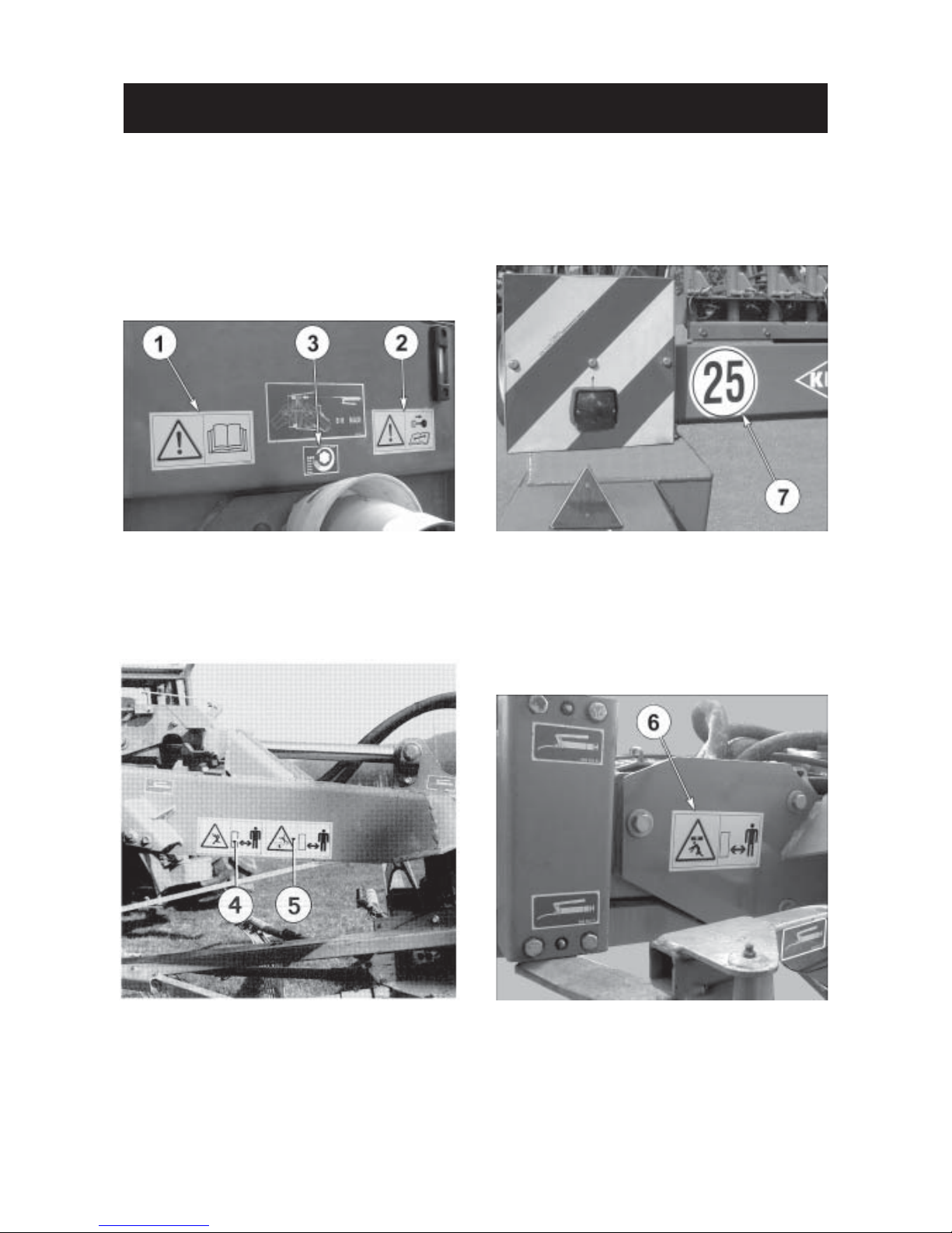
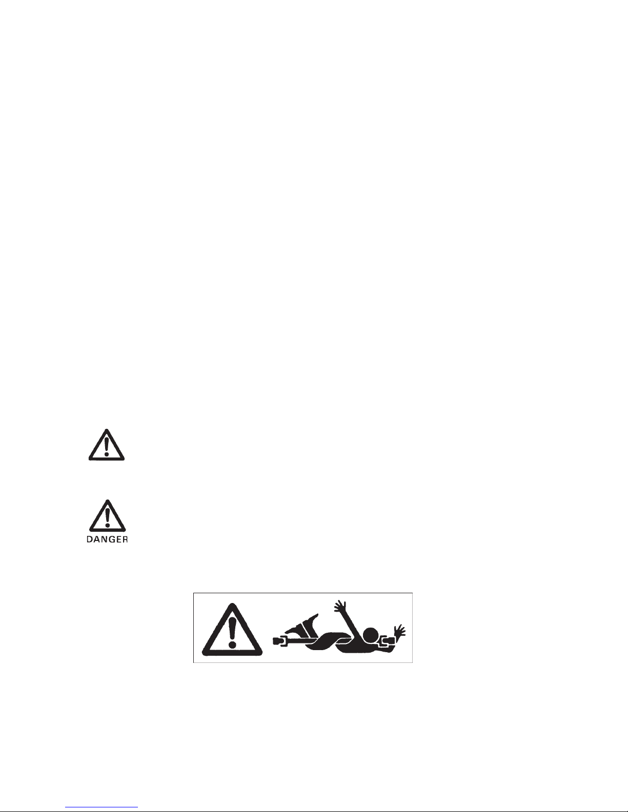
THE FOLLOWING SAFETY PICTORIALS HAVE BEEN PLACED ON YOUR MACHINE IN THE
AREAS INDICATED. THEY ARE INTENDED FOR YOUR PERSONAL SAFETY AND FOR THE
SAFETY OF THE PEOPLE WORKING WITH YOU. THE TEXT SHOWN ON THEM GIVES THEIR
PRECISE MEANING. ENSURE THAT THESE PICTORIALS ARE ALWAYS LEGIBLE. IF THEY ARE
NOT, REPLACE THEM.
SAFETY DECALS
Page 11

- 9 -
Page 12

- 10 -
- N o t e s -
Page 13

- 11 -
TECHNICAL SPECIFICATIONS
Technical Specifications GA 8001 H
Tractor attachment (category 2 and 3) Swivel hitch / lower links
Number of rotors
2
Number of tine arms / rotor 13
Working width max. 8.00 m (26' 3")
Transport width 3.00 m (9' 10")
Transport height with guards folded and
tine arms disconnected 4.00 m (13' 1")
Total length 6.80 m (22' 4")
Power requirement mini. 51.5 kW (70 hp)
PTO speed (rotational frequency) 540 rpm (min-1)
Drive :
- primary PTO shaft with constant velocity joints without torque limiter
- secondary hydraulic drive self contained unit with
pressure relief valve
Total weight 2980 kg (6556 lbs)
Tires / tire pressure :
- rotor undercarriage 18 x 8.5 - 8 (2 bars/29 psi)
- carrying frame 12.5 / 80 -18 (3 bars/45 psi)
Hydraulic outlet required 1 x double acting outlet
Electric connection required 1 x 7 pin plug
Special features : - The GA 8001 H is a machine conceived for large fields and has been designed to form one
central windrow of a set width.
- In transport position, the GA 8001 H guards are folded and the tine arms disconnected
which reduces considerably the height of the machine.
- The rear guide wheels of the GA 8001 H are angled from the pivoting head by means of
rods.
- The GA 8001 H is equipped with an hydraulic rotor drive. A pressure relief valve limits the
system's torque to a pre-set amount.
Page 14

- 12 -
ASSEMBLY INSTRUCTIONS
According to their destination, GA 8001 H units can be packed in crates, some parts or part units being
disassembled to facilitate their packing-up.
For reduced bulk, the main beam of the machine frame is not packed in a crate. To mount the various parts,
proceed as follows :
1. Unpacking
Carefully unpack all parts and spread them on the ground for easier identification.
The various hardware bags are numbered for easier identification. Make sure to use the hardware bag number
indicated in the various assembly sections.
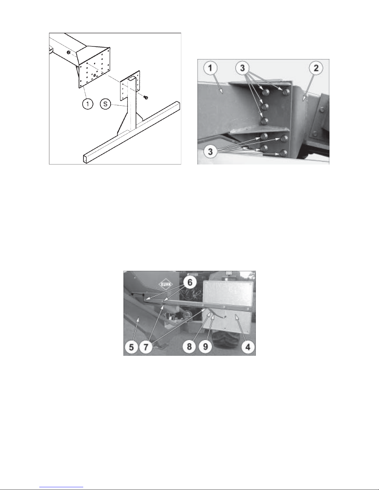
2. Assembly of the rear undercarriage to the frame (figure 1 and photo 1 A)
- Place the frame (1) on trestles and remove the support (S) which can be stored away together with its mounting
hardware.
- Using a hoist, bring the rear undercarriage (2) close to the frame (1).
Assemble both parts together with the 20 self-locking screws (3) (M 16 x 35) and 20 self-locking nuts (4) (M
16) located in the hardware parcel marked «montage train arrière» 078 709 10. Torque : 28 daNm/ 200 ft.lbs.
3. Mounting of the front signalling panels (photo 2)
- Mount the pre-assembled front signalling panels (4) on each side of the headstock (5) using 4 hexagonal screws
(6) (M 10 x 60) and 4 self-locking nuts (M 10). The red corners must be directed towards the top and outer side
of the machine.
- Fit the 2 self-adhesive bases (7) on each panel support (4) and place 1 collar (10) in each base.
- Connect the terminals (8) of the wiring harness in terminals (9) of the front lights. The locking tab (19) of the
female connector (20) must be fully engaged over the peg (21) of the male connector (22) (see figure
A, page 15).
- Tighten the collars.
The necessary mounting hardware is located in the parcel marked «montage panneaux de signalisation avant»
078 707 00.
Page 15
- 13 -
2
1A
1
Page 16

- 14 -
5. Parking the machine (photo B)
- Pull on lock handle (23).
- Slide parking stand (24) until lock (23) automatically locates in place.
ATTENTION : Always double check lock (23) is engaged.
- Raise the frame using a hoist and remove the trestles.
- Lower the machine and park it on the ground.
4. Finishing of the rear undercarriage mounting (figure 3)
- Mount the pre-assembled mudguards (1) on the wheel arms (2) using 12 self-tapping screws (M 8 x 20) packed
in the mounting hardware marked «montage garde-boue» 078 714 00.
- Mount the wheels(3) on hubs (4) using 12 wheel nuts (5) (torque : 10 daNm / 75 ft.lbs).
- Place 6 self-sticking supports(6) with their clamp collars on the rear sub-frame. Pull the electric wire with the
white end (7) through the left crossbar (8) (seen in the direction of travel) and the electric wire with the black
end (9) through the right crossbar.
- Mount the pre-assembled rear signalling panel units (10) on the rear wheel frame (11) using 6 self-locking
screws (12) (M 10 x 25). The red corners must be pointing upwards and outwards.
- Mount the tine arm supports (13) and the cover plate (14) on the rear wheel frame (11) with 12 self-tapping
screws (15) (M 8 x 20), 12 plain washers (diameter 9 x 30 x 1,5), 4 self-locking screws (16) (M 10 x 25).
- 2 self-tapping nuts (15) (M 8 x 20) are used to fit the SMV support.
- Plug the 4 pin terminals into the rear lights (17). Note that the rear left light connector is marked "L" and
is identified by a white cable sheath (highlighted in grey on fig. A).
The locking tab (19) of the female connector (20) must be fully engaged over the peg (21) of
the male connector (22) (fig. A).The cable ends should be slightly slack. Tighten the collars starting with
the rear of the machine.
- Place the bushes (18) in the tine arm storage racks (13).
The necessary mounting hardware for the cover plate (14), the rear signalling panels (10), the electric wires (7
and 9) and the tine arm storage racks (13) are located in the parcel marked «montage des panneaux de
signalisation arrière» 078 708 10.
Page 17

- 15 -
A
44A
3
3A
B
Page 18

- 16 -
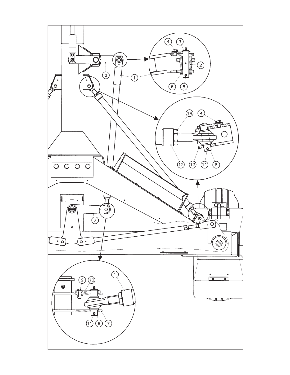
6. Fitting the rear track rod and the tie-rods (fig. 5)
- The rear drag link (1) is fitted on the rear lever (2) using pin (3) (diameter 22 mm), self locking screw (4) (M10
x 16), roll pin (5) (diameter 8 x 45) and plain washer (6) (diameter 23 x 45 x 3 mm) and the other end on the
steering lever (7) using pin (8) (diameter 25 mm), hexagon bolt (9) (M 10 x 30), a self-locking nut (10) (M 10)
and a roll pin (11) (diameter 8 x 45).
The necessary mounting hardware is packed in a parcel marked «montage bielle arrière» 078 710 00.
- Adjust the length of both tie-rods (12) and mount them on each side at the rear of the machine on the mounting
yokes (13) with 4 axles (diameter 25), 4 self-locking screws (4) (M 10x16) and 4 roll-pins (11) (diameter 8x45).
Once mounting is completed, shorten the tie-rods to eliminate all free movement, put then slightly under
tension and tighten the counter-nuts (14).
The required mounting hardware is located in a parcel named montage train arrière 078 709 10.
Page 19
- 17 -
5
Page 20

- 18 -
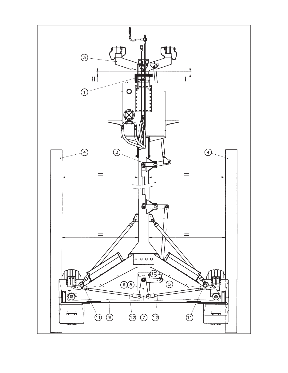
7. Adjusting the transport wheels (fig. 6)
The transport wheel alignment is pre-set in the factory. However, this setting can be checked using 2 straight
boards (4) placed against the sides of the transport wheels.
Position hole (6) punched in lever (7) under hole (8) of the rear wheel column support (9). The boards (4) should
be parallel to the frame tube. If not, proceed as follows :
- Adjust yoke (11) on the drag link (12) of the wheel(s) concerned until the correct parallelism is obtained. Make
sure hole (6) remains positioned under hole (8).
- Retighten the counter-nuts on yoke (11).
- Remove the pin which connects toggle joint (5) to lever (7).
- Place the swivel hitch (3) perpendicular to the frame tube using a set square (1). Position the rear side of swivel
hitch (3) parallel to the second side of the set square.
- Adjust the toggle joint (5) of the rear track rod so that the mounting pin holes line up.
- Install pin and secure it in place.
- Tighten counter-nut (10).
Page 21
- 19 -
6
Page 22

- 20 -
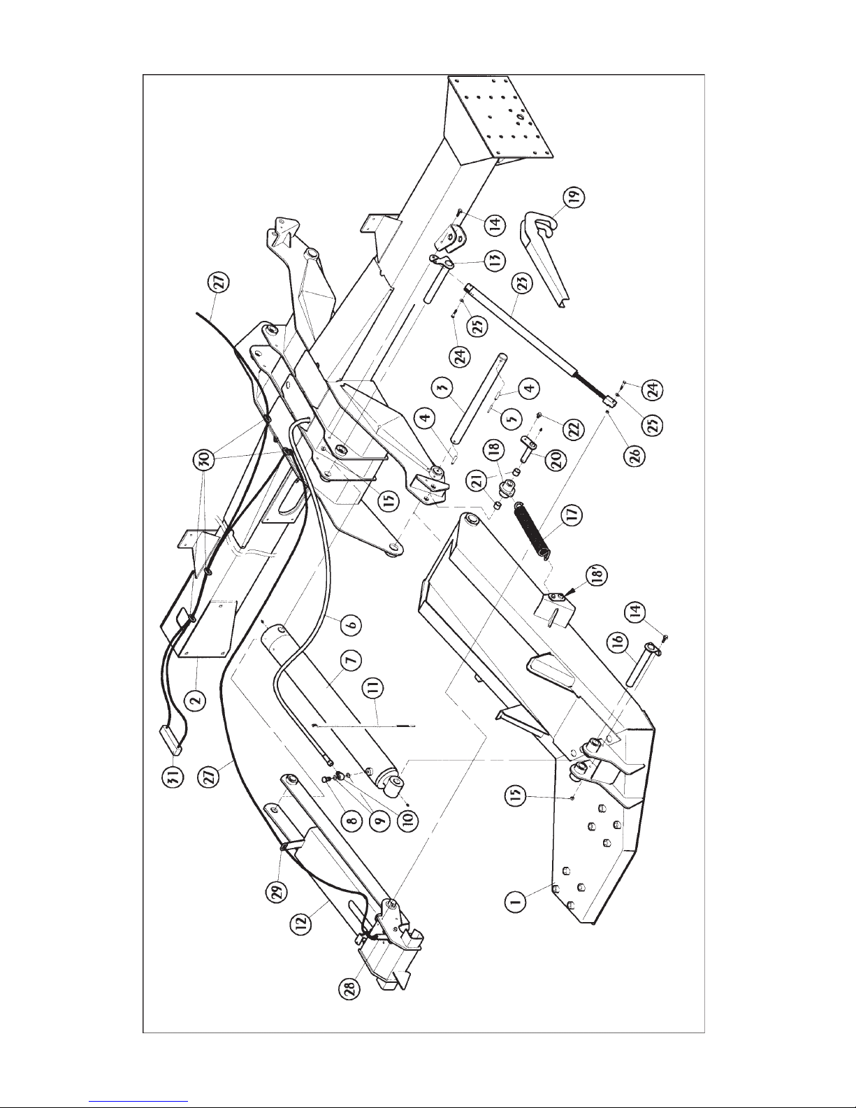
8. Mounting of rotor arms and lift cylinders (fig. 7)
- Fit the left rotor arm (1) onto the chassis (2) using pin (3), 2 roll pins (4) diameter 10 x 80) and 1 roll pin (5)
(diameter 6 x 85). Install the roll pin (5) on the side where roll pin (4) is placed in the welded bush.
- Mount a grease zerk onto the cylinder and cylinder rod.
- Mount the hydraulic hose (6) onto the cylinder (7) using 1 hollow grub screw (8) after having placed a copper
washer (9) on each side of the banjo bolt (10) and install a clamp collar (11).
- Slide the cylinder (7) in the cylinder lock unit (12) and mount this pre-assembled unit on the chassis (2) using
the pin (13), 1 self-locking screw (14) (M 10 x 25) and 1 self-locking nut (15) (M 10).
- Mount the cylinder rod on the rotor arm (1) with a pin (16), 1 self-locking screw (14) (M 10 x 25) and 1 self-locking
nut (15) (M 10).
The necessary mounting hardware for mounting the rotor arms and cylinders is packed in the parcel marked
«montage vérins» 078 712 00.
- Fit the 2 self-lubricating bushes (21) in housing (18).
- Attach the traction spring (17) to the housings (18 and 18). Using the special key (19), position the housing
(18) in order to be able to mount the pin (20) and secure it with the self-locking screw (22) (M 10 x 16).
- Mount a grease zerk on the pin (20).
The necessery mounting hardware for mounting the traction springs is packed in the parcel marked «montage
ressort de traction» 078 711 00.
- Mount the compensating tie-rod (23) onto the pin mounting bracket (13) using 1 hexagonal screw (24) (M 8
x 40) and 1 plain washer (25) (diameter 9x18x1.5) and onto the cylinder lock unit(12) with 1 hexagonal screw
(24) (M 8 x 40), 1 plain washer (25) (diameter 9 x 18 x 1.5) and 1 hexagonal nut (26) (M 8).
The necesseray mounting hardware for mounting the compensating tie-rods is packed in the parcel marked
«montage ressort de compensation» 078 713 00.
- Repeat the same operations for the right rotor arm.
9. Mounting of the arm lock manoeuvring cords (fig. 7)
- Pass the manoeuvring cords (27) through the levers (28) of the cylinder locks (12) and tie a knot.
- Pull the cords through the eyelets (29 and 30) on the cylinder lock units (12) and the main beam (2).
- Thread the cords through the handle (31), tie a knot at an adequate length leaving room to manoeuvre easily
from the tractor cab, then cut the surplus of cord at the base of the knots.
Page 23
- 21 -
7
Page 24

- 22 -
10. Mounting of the rotors and connection of hydraulic hoses (fig. 8)
- Mount each rotor (1) on a rotor arm (2) using 4 hexagonal screws (3) (M 16 x 130), 4 hexagonal screws (4)
(M 16 x 160) and 8 self-locking nuts (5) (M 16) as shown on figure 8 (torque : 20 daNm/150 ft.lbs). The necessary
mounting hardware is packed in a parcel marked «montage rotors » 078 715 00.
- Connect the hydraulic hoses (6 and 7) on the rotor hydraulic motors (13) using the adaptable elbows (8 and
9), the adapters (10 and 11) and the bushes (12) as shown on figure 8. Connect the large diameter hydraulic
hose (7) to the upper outlet of the hydraulic motor (13) on the left side (seen in the forward direction) and on
the lower outlet on the right side.
The mounting hardware is packed in a parcel marked «montage flexibles» 078 719 00.
11. Mounting of the rotor undercarriage wheels (fig. 8)
Slide the cylindrical hub protectors (14) in place until they seat on the axles shoulders. Then slide the conical
grey protectors (15) onto the axles with the conical side facing the wheel bearing locations. The grey protecting
plugs are seated tightly on the spindles shoulders. Drive them in place using a driver and apply a blow with a
hammer.
Fill the wheel caps (16) with grease. Also grease the space between both bearings located inside the rims. Mount
the 4 wheels (17) on axles. Insert bushes (18) and screw on low hexagon nuts (19) (M 16 x 1,5) (torque : 10daNm/
75 ft.lbs). Fit wheel caps (16) in place.
The necessary mounting hardware is packed in a parcel marked «montage roulettes» 078 716 00.
Page 25

- 23 -
Page 26

- 24 -
12. Fitting tine arms and tines (fig. 9)
- First fit tine arms (1) on supports (2) by means of of linchpins (3).
- Connect small hook of cord (4) to the ring of linchpin (3) then attach the larger hook of cord (4) to hole (5) of
tine arm lug.
- Next fit supports (2) with tine arms (1) on the gearbox oscillating shafts (6) by means of roll pins (8)
(diameter 12 x 55) and (7) (diameter 7 x 55).
Attention : The right and left-hand rotor arms are symetrically curved to one another. Ensure they are
positioned so that the curved portion is facing the front as seen in the direction of rotation
(see arrows figure 9).
.
Attention : Make sure slots in pins (7) and (8) are opposite to one another in the direction of the main effort
(see drawing on figure 9).
Clean and grease disconnectable tine arm stubs (1) regularly with a never-seize
compound.
- Attach tines (9) under tine arms (1) so that they face in the direction opposite rotor rotation indicated by the
arrow.
- To fit the tine arms use :
. 1 hexagonal bolt (10) (M 12 x 75)
. 1 flat washer (11) (diameter 13 x 35 x 7)
. 1 tine bracket (12)
. 1 spring washer (13)
. 1 self-locking nut (14)
Make sure these parts are positioned correctly.
Page 27

- 25 -
Page 28

- 26 -
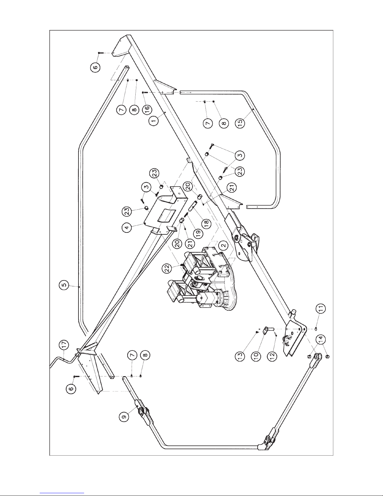
13. Mounting of the safety guards (fig. 10)
- Then attach the coupling hose (18) and the traction spring (19) to the lower end of the adjustment screw (22)
using 1 bush (20) and 1 roll pin (21) (diameter 6 x 40).
- Mount the left rear crossbar (1) on the rear side of the swinging arm (2) using 4 self-locking screws (3) (M 12
x 55) and 4 spacers (23) (diameter 13 x 25 x 25).
- Mount the left side beam (4) on the swinging arm (2) and the rear crossbar (1) using 6 self-locking screws (3)
(M 12 x 55) and 6 spacers (23) (diameter 13 x 25 x 25). Torque : 8.5 daNm/ 60 ft.lbs.
- Mount the inner tube (5) of the left safety guard on the side beam (4) and the rear crossbar (1) with 4 hexagonal
screws (6) (M 10 x 50), 4 plain washers (7) (diameter 11 x 24 x 2) and 4 self-locking nuts (8) (M10).
- Mount one end of the left foldable safety guard (9) on the side beam (4) with 2 hexagonal screws (6) (M 10 x
50), 2 plain washers (7) (diameter 11x24x2) and 2 self-locking nuts (8) (M10), and on the other side on the rear
crossbar (1) with 1 pin (10), 1 to 3 plain washers (11) (diameter 22.5x30x1) according to the clearance, 1 roll
pin (12) (diameter 8 x 40) and 1 self-locking screw (13) (M 10x16). Check that the self-lubricating bushes(14)
are installed in their housing.
- Mount the rear safety guard (15) on the rear crossbar (1) using 4 hexagonal screws (16) (M 10x55), 4 plain
washers (7) (diameter 11x24x2) and 4 self-locking nuts (8) (M 10).
- Install the crank handle (17) passing it through the holes of the side beams bracket (4).
- Then attach the coupling hose (18) to the crank handle (17) using 1 bush (20) and 1 roll pin (21) (diameter 6
x 40).
- Mount a grease zerk on the pin (10)
- Proceed in the same way to mount the right safety guard.
The necessary mounting hardware is packed in a parcel marked «protecteurs» 078 717 10.
Page 29
- 27 -
10
Page 30

- 28 -
The GA 8001 H Gyrorake can be fitted to all tractors with a standard three-point linkage Cat. 2 or 3 and a power
comprised between 51 and 74 kW (70 and 100 hp).
The swivel hitch is equipped with two attachment yokes (1) to be connected to the tractor lower links (2)
(photo 11).
Attachment should always be made within yokes (1). Two bushes (diameter 37 mm / 1 1/2") are supplied with
the machine for attachment to Cat. 3 tractors.
Always make sure the tractor lower links are immobilized using the means provided (check chains, etc...)
It is very important that the tractor lower links (2) are horizontal and that the the lower hitch pins are set at approx.
600 mm / 2' above ground level (see distance A). This distance may be set permanently using the optional
check chain kit.
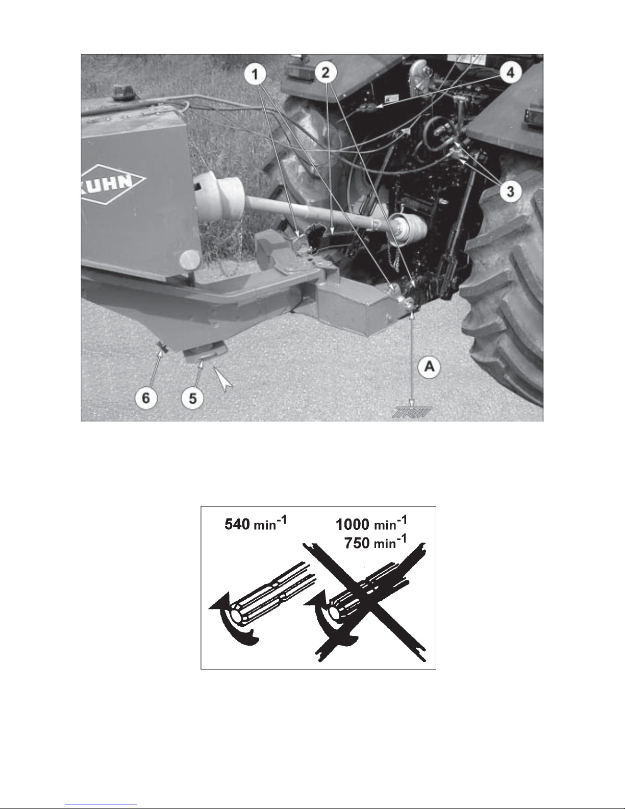
Connect hydraulic hoses (3) and electric plug (4) of the light and signal system (photo 11). To do this a double
acting outlet and a 7-pin electric socket at the rear of the tractor are required.
When the machine is attached to the tractor, retract the parking stand (5) in its housing (see arrow) and lock it
with the locking handle (6) (photo 11). 2 handles have been welded on the parking stand (5) to ease its handling.
ATTACHMENT
1) FITTING TO THE TRACTOR
Page 31
- 29 -
11
Page 32
- 30 -
2) PTO TRANSMISSION SHAFT WITH CONSTANT VELOCITY JOINTS
Connect the PTO shaft to the 540 rpm (min-1) tractor drive (outer guard tube on the machine side).
Make sure PTO length is correct :
1) When the PTO is in its maximum extended position, a minimum tube overlap of 300 mm (12") must be
maintained.
2) When the PTO is in its maximum overlap position (retracted), tubes must not butt against the yokes. As a
safety measure a clearance of at least 2 cm (3/4") must be maintained (fig. 16). If this is not the case, shorten
the two transmission tubes and the two guard tubes by the same length (fig.12 and 13). Bevel and clean the
tubes (fig.14) and grease the inside of the outer tube (fig.15).
If the tractor power take off stub or the machine input stub are out of line with the tractor's central line
(distance A) :
The maximum overlap position (distance L) is obtained by fully pivoting the headstock to the side where the
tractor power take off stub/machine input stub is located (angle ).
Also ensure that the power take off shaft will not bottom out when pivoting the headstock at it's maximum in
the opposite direction.
If the stubs are in line with the tractor centre :
The maximum overlap position (distance L) is obtained by pivoting the headstock at it's maximum angle either
to the right or to the left.
These recommendations and adjustments must be respected to avoid damage or premature wear
of the PTO.
Never connect the PTO to the 1000 rpm (min-1) tractor drive.
To avoid accidents which could be serious, make sure that the guards are always correctly
in place and secured with the safety chains provided (photo 11). On the side of the machine,
the chain should be fixed on the hydraulic hose holder. Damaged guards must be replaced
immediately.
Page 33

- 31 -
Page 34

- 32 -
WORK POSITION AND ADJUSTMENTS
BEFORE CARRYING OUT ANY OPERATION SUCH AS MAINTENANCE OR ADJUSTMENT ON THE MACHINE, STOP THE TRACTOR ENGINE, REMOVE IGNITION KEY AND
WAIT FOR ROTATING PARTS TO STOP.
MAKE SURE THERE IS NOBODY IN THE MACHINE OPERATING AREA BEFORE LOWERING
THE ROTORS INTO THEIR WORK POSITION.
To switch the GA 8001 H from the transport position to the work position, proceed as follows :
- Pressurize the hydraulic cylinders so that they close up against their stops.
- Pull cords (1) (photo 17) to unlock rotor arms.
- Shift the tractor valve to lower the rotors. Release cord (1) once rotors start being lowered.
- Once the rotors are completely lowered, the machine is in the working position (photo 19).
- Remove tine arms from their racks and fit them on the rotors (see page 24).
- Unlock foldable guards (4) using handles (3) and fold them outwards into the work position (see arrows, photo
18).
- Store handles (3) in the spring clips (2) (photo 18).
Maintain the tractor hydraulic valve in the free floating position during work.
Wheel undercarriage height adjustment (photo 20) :
- Using the tractor hydraulics, slightly lift the rotors to clear the wheels off the ground,
- adjust the desired height of the undercarriage by rotating the crank (5),
- activate the tractor hydraulics to lower the rotors on the ground.
Note : The oblong holes (6) are used as marks enabling to check that both undercarriages are adjusted at the
same height.
Page 35

- 33 -
17
19
Page 36

- 34 -
OPERATION
The GA 8001 H must not be operated using a PTO speed (rotational frequency) above 540 rpm (min-1) (see
figure 21).
The GA 8001 H is a machine conceived for large fields and has been designed to form one central
windrow of a set width.
The GA 8001 H is equipped with an hydraulic rotor drive. Check the oil level in the tank regularly
(machine stopped) (The oil level should be located between min. and max. marks) (see chapter
Lubrication).
NEVER LET THE ROTORS ROTATE WHEN THE MACHINE IS IN TRANSPORT
POSITION DUE TO RISKS OF ACCIDENT.
FORWARD SPEED
Forward speed must be determined in accordance with quantity of crop, type of terrain, etc. It is recommended
to always operate at a lower speed when working in difficult conditions, however it is not possible to recommend
specific speeds, these must be determined by the operator under the prevailing conditions.
Page 37

- 35 -
21
Page 38

- 36 -
TRANSPORT
KEEP ALL PERSONS AWAY FROM THE VICINITY OF THE MACHINE BEFORE
PIVOTING THE OUTER ROTORS INTO TRANSPORT POSITION.
IN TRANSPORT AND DURING WORK, THE PARKING STAND MUST ALWAYS BE IN
THE RAISED POSITION.
NEVER LET THE ROTORS ROTATE WHEN THE MACHINE IS IN TRANSPORT
POSITION DUE TO RISKS OF ACCIDENT.
NEVER TRANSPORT THE GA 8001 H AT MORE THAN 25 KM/H (16MPH).
To fold the machine into the transport position (photo 26), proceed as follows :
- Use handles (3) to unlock safety guards (2) and fold them to the inside (see arrows, photo 22). Guards will
automatically be locked in place once in the transport position.
- Store handles (3) in the spring clips (4) (photo 22).
- Disconnect the tines arms (5) on each rotor and place them into the racks (6 and 7)provided (photo 23).
Secure tine arms (5) with linch pins (photo 23).
- From the tractor seat, pull on cords (8) (photo 24) and activate the tractors hydraulics to raise the rotors.
- Once the rotors are raised into the transport position, release the cord and make sure that the locks (9 and
10) are properly engaged (photo 25).
- Check that plug of the light and signal system is properly connected and ensure that all signal lights are
functioning correctly.
TRANSPORT OF THE MACHINE ON ROADS IS THE OPERATORS RESPONSIBILITY
AND HE MUST ENSURE THAT THE MACHINE IS IN LINE WITH THE HIGHWAY CODE
OF THE COUNTRY CONCERNED.
ALWAYS CHECK THAT THE REAR LIGHTS AND INDICATORS ARE CLEAN AND
FUNCTIONING CORRECTLY BEFORE GOING ON THE ROAD.
Page 39

- 37 -
26
24
23
Page 40

- 38 -
PARKING THE MACHINE
MAKE SURE THAT THE TINE ARMS ARE DISCONNECTED AND HOUSED IN THEIR RACKS
BEFORE PARKING THE MACHINE IN ITS TRANSPORT POSITION (ROTORS RAISED).
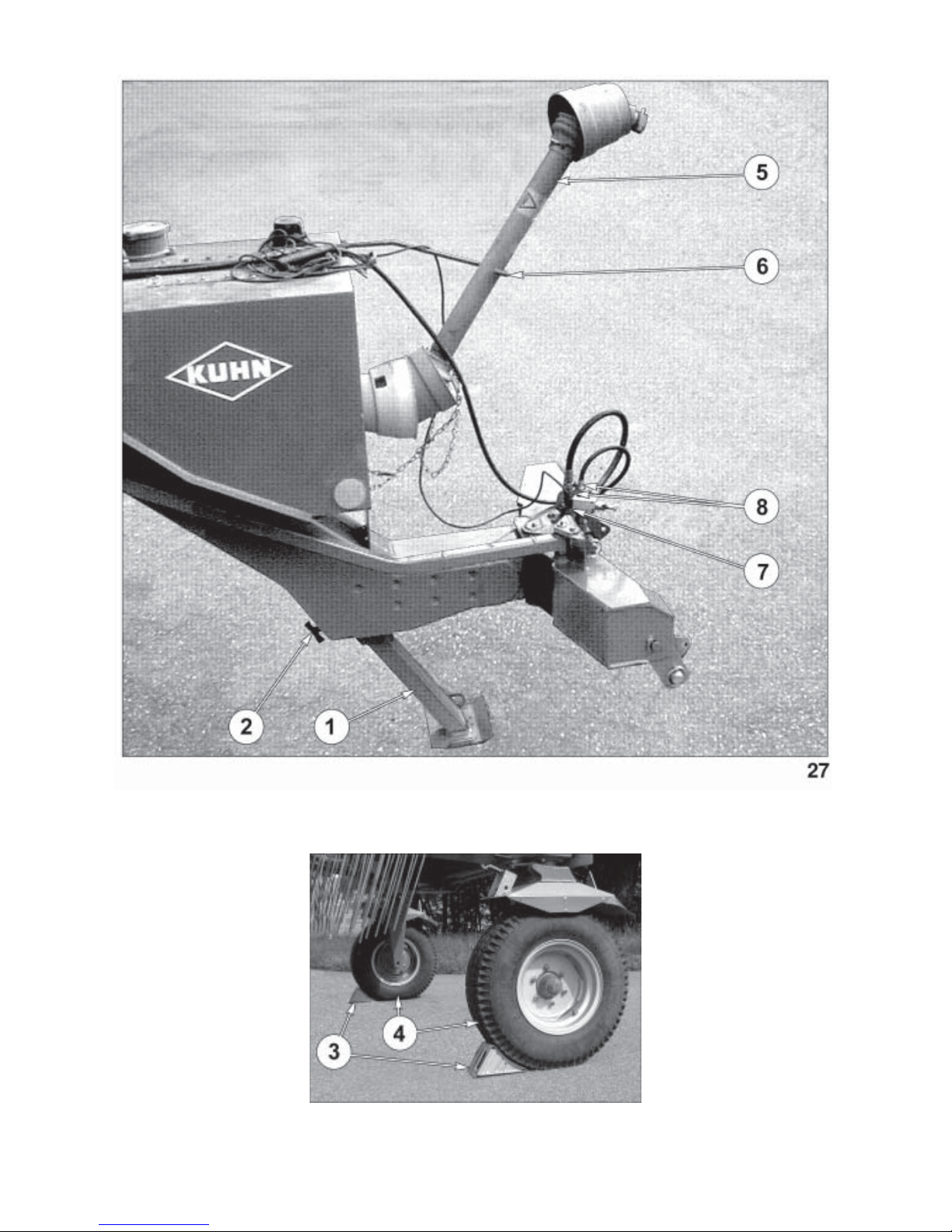
The GA 8001 H is equipped with a parking stand (1) to park the machine in its work or transport position.
To park the machine, proceed as follows :
- Pull handle (2) to free parking stand (1) and slide it down until the stand automatically locks into place
(photo 27).
- Lower the tractor 3-point linkage untill the machine rests on parking stand (1).
- Place two metallic wedges (3) under the transport wheels (4) (photo 28).
- Disconnect machine from tractor.
- Place main PTO shaft (5) in the support (6) provided (photo 27).
- Put light and signal plug (7) and male couplings (8) of the hydraulic hoses into their parking supports (photo
27).
ALWAYS PARK THE MACHINE ON EVEN, FAIRLY LEVEL GROUND.
Page 41
- 39 -
28
Page 42

- 40 -
LUBRICATION
ALL GREASE POINTS ARE MARKED WITH THE
FOLLOWING STICKER :
All GA 8001 H grease points are marked A on photos 29 to 35.
For good machine operation, grease all grease points with SHELL Multi-purpose grease NLGI2 as follows :
Every 8 hours :
- All wide angle PTO shaft U-joints and telescoping
tubes.
Note : Pay particular attention to the central grease
fitting of the CV joints. Up to 20 pumps of
grease may be required to fill the CV joint
reservoirs correctly (see sticker opposite).
Once a week :
- the guides of the drag links and the swivel hitch (photos 29, 30 and 31)
- transport wheel arm pivot points (photo 29)
- rotor arm pivot points on the frame (photo 32)
- pivot points of the rotor lift cylinders (photo 32)
- pivot points of the rotor gearboxes (photo 33)
- tine arm bushes (photos 33 and 34)
- foldable guard pivot points (photo 35).
Regularly clean and apply a «Never-seize» compound to the removable portion of the tine arms to ensure easy
removal.
THE RECOMMENDED GREASE AND OIL CHANGE PERIODS ARE BASED ON NORMAL
FIELD AND WORK CONDITIONS.
SEVERE OR UNUSUAL CONDITIONS MAY REQUIRE MORE FREQUENT LUBRICATION
OR OIL CHANGES.
Page 43

- 41 -
31
30
29
Page 44

- 42 -
As required, lubricate :
- rotor arm locks
- guard and parking stand locks
- pivoting lower hitch points.
The hydraulic tank (1) in factory filled with 185 litres of multipurpose mineral oil SHELL AGROMA 15W40.
Every 2 years or more often if necessary, drain the tank and replace the oil filter located underneath the top plug
(2) (photo 36). Fill with SHELL AGROMA 15W40 multipurpose oil or with an other mineral hydraulic oil of which
the viscosity corresponds to the ISO VG 100 and of HV type standards.
Regularly check the oil level of the hydraulic tank. The level is correct when located between the MINI and MAXI
marks of the sight glass (3) (photo 36). If necessary, adjust the oil level.
TO ENSURE TROUBLE FREE OPERATION OF YOUR MACHINE,
WE RECOMMEND SHELL LUBRICANTS.
OPTIONAL ACCESSORY
1° CHECK CHAIN KIT (No. 108 6530) (photo 29)
These chains may be recommended when operating with certain tractors with older style hydraulics which would
not allow a steady swivel head ground clearance to be maintained during work. They also help prevent the PTO
shaft from bottoming out should the lift linkage be lowered accidentally.
To install chains proceed as follows :
- Connect the tractor lower link arms to the hitch brackets (C) (see section Attachment of the machine).
- Raise the tractor hydraulic linkage until the swivel head lower links clear the ground by approx. 700 mm / 28".
- Attach one end of chains to hitch brackets (C) with D-hangers (H) and their other end to the tractor top link pin.
- Completely lower the tractor linkage. Height adjustment is correct when :
. lower link arms (T) are level,
. chains are tight,
. distance (A) between hitch pins and ground is 600 mm / 24".
Page 45

- 43 -
37
36
Page 46

- 44 -
ELECTRICAL CONNECTOR (for North America)
KUHN wiring harnesses are supplied with an ISO (International Standards Organization) 1724 plug
connector.If the implement is to be operated with a tractor equipped with an SAE style seven-pin
connector a SA J 560b plug must be installed. If required, the SAE J 560b plug is factory supplied
with the machine.
Implement wiring harness description
Colors Function Terminal connection
ISO 1724 plug SAE J 560b plug
White Ground 3 1
Black Left running lights 7 6 *
Yellow Left turn & hazard 1 3
Red Stop lights 6 4 **
Green Right turn & hazard 4 5
Brown Right running lights 5 6 *
Blue Not used 2 7
* Note that the black and brown wires must be connected together on SAE type connectors for proper
light opération.
** The red wire should only be attached to the #4 terminal if the #4 terminal on the tractor is confirmed
to be a brake light terminal. If the tractor has no brake terminal the red wire of the implement should
be sealed off and not connected to any terminal.
Page 47

- 45 -
SOUND LEVELS
Sound levels given out by : GA 8001 H Gyrorake
Sound levels have been measured in accordance with the measuring methods as defined in :
HM Agricultural Inspectorate
AGRICULTURAL MACHINERY NOISE
Legislation and guidance on methods of testing
(Annex to AIC 1896/117 REV)
February 1988
Health and Safety Executive
The method employed corresponds to the method No. 4 in this document. Unspecified testing
conditions comply with ISO 5131 standard.
Measuring equipment conforms to NF S 31-009 standard. The tractor used has a power of 58 kW.
A-weighted emission sound pressure level L (A) eq inside tractor cab (with closed windows) :
Tractor only : 78.0 dB (A)
Tractor + machine : 76.0 db (A)
Page 48

LIMITED WARRANTY
KUHN S.A. of 4 Impasse des Fabriques, 67706 SAVERNE CEDEX, France (hereinafter called the
«Company») warrants, in accordance with the provisions below, to each original retail purchaser of
KUHN new equipment of its own manufacture, from an authorized KUHN dealer, that such equipment
is, at the time of delivery to such purchaser, free from defects in material and workmanship and that
such equipment will be warranted for a period of one year starting from the date the goods are delivered
to the end user and during this period up to a limit of 500 hours use, providing the machine is used and
serviced in accordance with the recommendations in the Operators Manual.
THESE CONDITIONS ARE SUBJECT TO THE FOLLOWING EXCEPTIONS :
1. Parts of machines which are not of our manufacture i.e. tyres, belts, P.T.O. shafts, clutches etc., are not
covered by this Limited Warranty but are subject to the warranty of the original manufacturer. Any claim
falling into this category will be taken up with the manufacturer concerned.
2. Warranty claims applying to these types of parts must be handled in the same way as if they were parts
manufactured by KUHN. However, compensation will be paid in accordance with the warranty agreement of the manufacturer concerned in as much as the latter justifies such a claim.
3. This Limited Warranty will be withdrawn if any equipment has been used for purposes other than for
which it was intended or if it has been misused, neglected or damaged by accident or let out on hire. Nor
can claims be accepted if parts other than those manufactured by us have been incorporated in any of
our equipment. Furthermore, the Company shall not be responsible for damage in transit or handling by
any common carrier and under no circumstances within or without the warranty period will the Company
be liable for damages for loss of use or damages resulting from delay or any consequential damage.
We cannot be held responsible for loss of earnings caused by a breakdown or for injuries either to the owner
or to a third party, nor can we be called upon to be responsible for labor charges, other than originally
agreed, incurred in the removal or replacements of components.
THE CUSTOMER WILL BE RESPONSIBLE FOR AND BEAR THE COSTS OF:
1. Normal maintenance such as greasing, maintenance of oil levels, minor adjustments, etc.
2. Transportation of any kind of any KUHN product to and from the place the warranty work is performed.
3. Dealer travel time to and from the machine or to deliver and return the machine from the workshop for
repair.
4. Dealer travelling costs.
Parts defined as normal wearing items are listed as follows and are not in any way covered under this
Limited Warranty :
V belts, discs, knives, wear plates, disc guards, tires, torque limiters, hydraulic hoses, pitman shafts, swath
sticks, blades, tines and tine holders.
KUHN Limited Warranty will not apply to any product which is altered or modified without the expressed
permission of the Company and/or repaired by anyone other than Authorized Service Distributors or
Authorized Service Dealers.
Page 49

LIMITED WARRANTY IS DEPENDENT UPON THE STRICT OBSERVANCE BY THE
PURCHASER OF THE FOLLOWING PROVISIONS :
- That this Limited Warranty shall not be assigned or transferred to anyone unless the Companys consent in
writing has first been obtained.
- The warranty/product registration form has been correctly completed by dealer and purchaser with their
names and addresses, dated, signed and returned to the appropriate address as given on the warranty/
product registration form.
- The claim form sent to KUHN has been correctly completed stating:
* dealers name and address
* owners name and address
* type of machine
* machine serial number
* delivery date to buyer
* date of failure
* tractor make and type
* description of the failure and its cause
* quantity, reference number and name of the damaged parts
* reference number, quantity and date of the invoice for the replacement parts.
- The judgement of the Company in all cases of claims under this Limited Warranty shall be final and conclu-
sive and the purchaser agrees to accept its decisions on all questions as to defect and to the exchange of
any part or parts.
- That all safety instructions in the Operators Manual shall be followed and all safety guards regularly inspected
and replaced where necessary.
No warranty is given on second-hand products and none is to be implied. Persons dealing in the Companys
products are in no way legal agents of the Company and have no right or authority to assume any obligation
on their behalf, express implied, or to bind them in any way.
KUHN S.A. reserves the right to incorporate any change in design in its products without obligation to make
such changes on units previously manufactured.
Moreover, because of the constant progress in technology, no guarantee is given to the descriptions of
equipment published in any document by the company.
DISCLAIMER OF FURTHER WARRANTY
There are no warranties, expressed or implied, except as set forth above. There is no
warranty of merchantability. There are no warranties which extend beyond the description
of the product contained herein. In no event shall the company be liable for indirect, special
or consequential damages (such as loss of anticipated profits) in connection with the retail
purchasers use of the product.
Page 50

- N O T E S -
Page 51
This machine complies with the safety requirements of the European machinery directive.
The Operator should respect all Health and Safety regulations as well as the Highway
Code. For your own safety, use only genuine KUHN spare parts. The manufacturer
disclaims all responsibilities due to incorrect use or non-compliance with the
recommendations given in this manual.
Page 52

Printed in France by KUHN
KUHN S.A. 4 Impasse des Fabriques F - 67706 SAVERNE CEDEX (FRANCE)
Tél. : + 33 (0) 3 88 01 81 00 - Fax : + 33 (0) 3 88 01 81 03
www.kuhnsa.com - E-mail : info@kuhnsa.com
Société Anonyme au Capital de 19 488 000 Euros
For your safety
and to get the best from your machine,
use only genuine KUHN parts
 Loading...