

Page 1
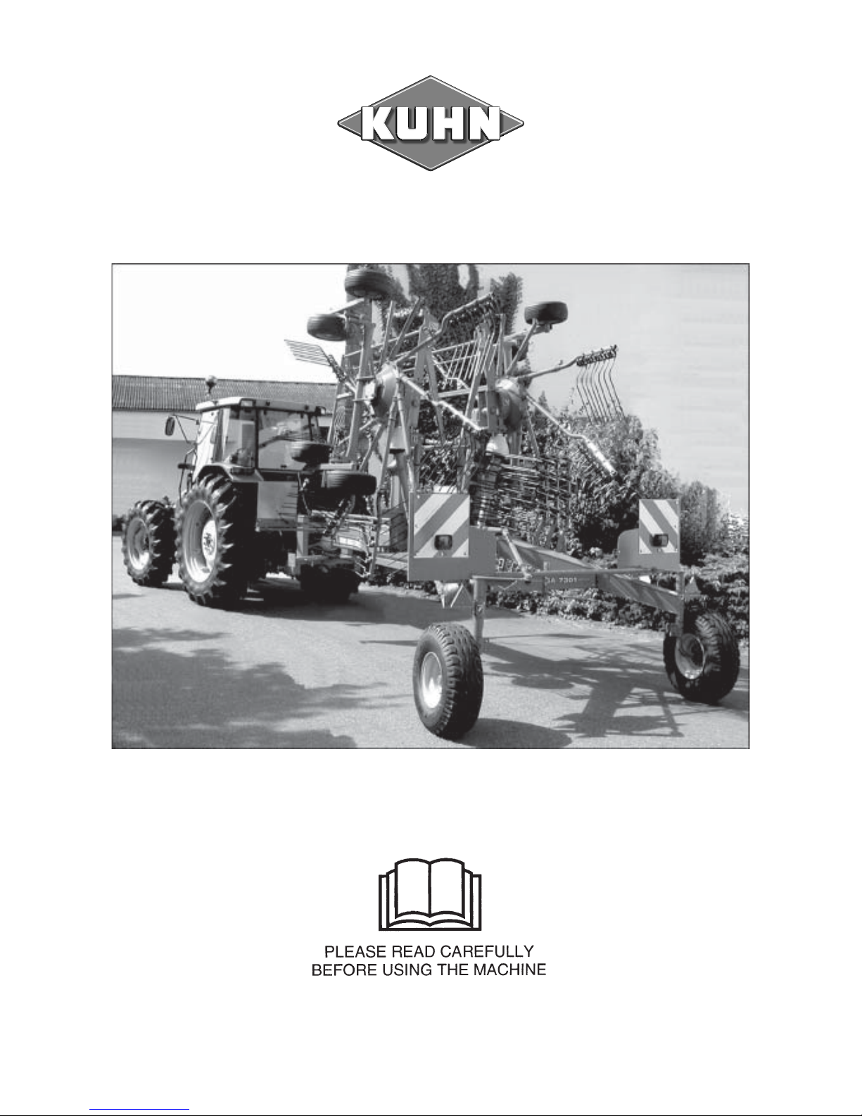
ASSEMBL Y / OPERA TORS MANUAL
GA 7301 - GYRORAKE
N° 95304 D.GB - 09.2003
Page 2
DEAR OWNER,
In buying a KUHN machine you have chosen wisely. Into it have gone years of thought,
research and improvements. You will find, as have thousands of owners all over the world, that
you have the best that engineering skill and actual field testing can produce. You have
purchased a dependable machine, but only by proper care and operation can you expect to
receive the performance and long service built into it.
This manual contains all the necessary information for you to receive full efficiency from your
machine. The performance you get from this machine is largely dependant upon how well you
read and understand this manual and apply this knowledge. Please DO NOT ASSUME THAT
YOU KNOW HOW TO OPERATE AND MAINTAIN YOUR MACHINE before reading this
manual carefully. KEEP THIS MANUAL AVAILABLE FOR REFERENCE.
Your KUHN dealer will instruct you on the general operation of your machine. He is interested
that you get the best performance possible and will be glad to answer any special questions
that may arise regarding the operation of the KUHN machine.
Your KUHN dealer can offer a complete line of genuine KUHN service parts.
These parts are manufactured and carefully inspected in the same factory that builds the
machine to assure high quality and accurate fitting of any necessary replacements.
When ordering service parts it is important that you indicate the type of machine concerned
and its serial number.
For this reason please complete the model identification plate diagram below with the required
information. This will provide you with an easy reference for future service parts orders.
ABOUT IMPROVEMENTS
KUHN is continually striving to improve its products and, therefore, reserves the right to make
improvements or changes when it becomes practical to do so, without incurring any
obligations to make changes or additions to the equipment sold previously.
Page 3

- 1 -
CONTENTS
Safety 2
Safety decals 8
Technical specifications 10
Assembly 10
Attachment : - Fitting to the tractor 20
- PTO transmission shaft 21
Working position and adjustments 22
Operation 24
Forward speed 24
Transport position 25
Parking the machine 26
Lubrication 26
Optional equipment 27
Electrical connector (for North America) 30
Conditions of limited warranty 32
Copyright 2003 KUHN S.A.
Page 4

- 2 -
SAFETY ADVICE
The above symbol is used throughout this manual every time recommendations are made concerning your safety,
the safety of others, or the good operation of the machine.
These recommendations must be made known to all machine operators.
DESIGNATED USE OF THE MACHINE
The GA7301 Gyrorake must only be used for the work for which it has been designed : raking on the ground and
forming windrows of pre-mowed fodder and straw.
The manufacturer is not held liable for any damage resulting from machine applications other than those
specified by the manufacturer.
Any use other than the designated operation is at the risk and responsibility of the operator.
Designated use of the machine also means :
- following operation, maintenance and repair recommendations given by the manufacturer ;
- using only genuine spare parts, equipment and accessories as designated by the manufacturer.
The GA 7301 Gyrorake must only be operated, maintained and repaired by competent persons who are familiar
with machine specifications and operation and are aware of any danger involved.
The operator must imperatively respect current legislation concerning :
- accident prevention,
- work safety,
- public traffic circulation.
All safety advice indicated on the machine must be strictly observed.
The manufacturer is not held liable for any damage resulting from machine modifications carried out by the
operator himself or by a third party without previous written agreement from the manufacturer.
Page 5

- 3 -
GENERAL SAFETY RECOMMENDATIONS
Before operating the machine, always ensure that tractor and machine are in accordance with work safety and road
traffic regulations.
BASIC PRINCIPLES
1. In addition to the recommendations given in this manual, legislation on work safety and accident prevention must
also be respected.
2. Advice is indicated on the machine, specifying safety recommendations in order to prevent accidents.
3. Before travelling on public roads, the operator must ensure that the machine conforms to road traffic regulations.
4. Before starting work, the operator must be familiar with all machine controls, handling devices and their
functions. Once at work, it is too late to do this !
5. Use a tractor equipped with a safety cab. Keep windows and roof hatch closed for reduced sound level while
operating the PTO drive implement.
6. Before starting up the machine and beginning work, check the surrounding area (beware of children !). Make
sure there is sufficient visibility.
Keep all people and animals away from the danger zone of the machine (risk of projection !)
7. Carrying people or animals on the machine when working or in transport is strictly forbidden.
8. Machine must only be attached to tractor using means provided and in accordance with current safety
standards.
9. When attaching or removing the machine, place the parking stand into the corresponding position.
10. Special care should be taken when attaching or removing the machine from the tractor.
11. Before attaching the machine, ensure that the front tractor axle is sufficiently ballasted.
Ballast is to be placed on the supports provided in accordance with instructions of the tractor manufacturer.
12. Do not exceed the maximum axle load or the overall transport weight as prescribed by the tractor manufacturer.
13. Do not exceed the maximum transport width authorized by road traffic regulations.
14. Before travelling on public roads, ensure that all legally required guards and indicators (lights, reflectors ...) are
in place and in good operation.
Page 6

- 4 -
15. All operating controls (cords, cables, rods...) must be positioned so that they cannot be set off accidently,
risking accident or damage.
16. Before traveling on public roads, put the machine into its transport position as instructed in this operator’s
manual.
17. Never leave the tractor seat while the machine is operating.
18. Drive speed must be adapted to ground conditions as well as to roads and paths.
Always avoid abrupt changes of direction.
19. Precision steering, tractor adherence, road holding and efficient braking are influenced by the type of
implement, weight, ballast of front axle, ground or road conditions. It is therefore of utmost importance to
be cautious in every given situation.
20. Be particularly cautious when turning corners, paying attention to machine overhang, length, height and
weight.
21. Keep clear of the machine operating area.
22. WARNING ! Danger of crushing and shearing can exist when components are operated by hydraulic or
pneumatic controls.
23. Before leaving the tractor or before adjusting, maintaining or repairing the machine, turn off the engine,
remove the ignition key and wait until all moving parts have come to a complete stop.
24. Do not stand between the tractor and the machine unless the hand brake is tight and/or stops have been
placed under the wheels.
25. Before any adjustments, maintenance or repairs are carried out, ensure that the machine cannot be started
up accidentally.
PRECAUTIONS TO BE TAKEN BEFORE OPERATING THE MACHINE
1. Do not wear loose clothing which could be caught up in moving parts.
2. Wear the individual protection equipment corresponding to the work which is planned (gloves, shoes, eye
protection, helmet, ear protectors...).
3. All operating controls (cords, cables, rods ...) must be positioned so that they cannot be set off accidentally,
causing accident or damage.
4. Before operating the machine, check the tightness of all nuts and bolts, particularly on rotating parts (blades,
tines, knives, spades ...)
5. Before operating the machine, ensure that all safety guards are firmly in place and in good condition. If worn
or damaged, replace immediately.
Page 7

- 5 -
Rotation speed ... rpm (American Measure) is also expressed in metric measure : Rotational frequency ... min
-1
.
Both units are equivalent, for example : Rotation speed 540 rpm equals Rotational frequency 540 min-1.
ATTACHMENT
1. When attaching or removing the machine from the tractor, position hydraulic lift control lever in such a way that
it cannot be set off accidentally.
2. When attaching the machine to the tractor hydraulic linkage, ensure that diameter of the link pins corresponds
to the diameter of the ball joints.
3. WARNING ! Danger of crushing and shearing can exist in the lifting zone of the tractor hydraulic linkage !
4. Do not stand between the tractor and the machine when operating the outer control lever of the lift mechanism.
5. In transport, the machine lift mechanism should be stabilized by tractor tie rods to avoid floatation and side
shifting.
POWER TAKE-OFF
1. Use only the PTO shaft supplied with the machine or recommended by the manufacturer.
2. PTO guards must always be in place and in good condition.
3. Check for correct PTO overlap when at work and in transport.
4. Before attaching or removing the PTO shaft, disengage PTO shaft, turn off engine and remove ignition key.
5. If a primary PTO shaft is equipped with a slip clutch or a free wheel, these must be fitted on the machine PTO.
6. Ensure that PTO shaft is always correctly fitted and locked into place.
7. Make sure guards are correctly in place and secured with the safety chains provided.
8. Before engaging PTO, ensure that PTO speed (PTO rotational frequency) and direction of rotation are in
accordance with manufacturers recommendations.
9. Before engaging PTO, keep all people and animals clear from the machine.
10. Never engage PTO shaft when tractor engine is turned off.
11. Never surpass the PTO angle recommended by the manufacturer.
Page 8

- 6 -
12. WARNING ! Rotating elements can continue turning momentarily after PTO is disengaged. Keep clear until all
rotating elements are at a standstill.
13. When removing the machine, place PTO shaft on the supports provided.
14. Fit the safety cap on tractor PTO.
15. Replace any worn or damaged PTO guards immediately.
HYDRAULIC SYSTEM
1. Beware ! The hydraulic circuit is under pressure (maximum working pressure : 200 bars/2900 psi).
2. When fitting hydraulic motors or cylinders, ensure that connections have been made correctly, as per
manufacturer’s instructions.
3. Before connecting hoses to the tractor hydraulics, ensure that tractor and machine circuits are not under
pressure.
4. It is strongly recommended that the operator marks the hydraulic connections between tractor and machine
to avoid making a wrong connection. WARNING ! Functions could be reversed (for example : lift/lower).
5. Regularly check the hydraulic hoses ! Replace the hydraulic hoses every 5 years. Damaged or worn hoses
must immediately be replaced .
When replacing the hydraulic hoses, make sure to use hoses with the specifications and quality recommended
by the manufacturer of the machine.
6. Should a leak be found, take all necessary precautions to avoid accidents.
7. Any liquid under pressure (particularly oil from hydraulics) can penetrate the skin and cause severe injury. If
injured, see a doctor immediately, there could be danger of infection.
8. Before any adjustments, maintenance or repairs are carried out, lower the machine, depressurize the circuit,
turn off the engine and remove ignition key.
Page 9

- 7 -
TIRES
1. Before any work is performed on the wheels, ensure that the machine rests on the ground and is perfectly stable
so that it cannot move accidentally (put wedges in place).
2. Assembly, disassembly and repair of wheels and tires must only be carried out by competent persons who
are equipped with standardized tools.
3. Check tire pressure regularly !
Respect manufacturer’s recommendations on tire pressure.
MAINTENANCE
1. Before checking for any machine malfunction and before adjusting, maintaining or repairing the machine,
disengage PTO, turn off engine and remove ignition key.
2. Check tightness of nuts and bolts regularly. Retighten if necessary.
3. If the machine is raised, prop it up in a stable position before carrying out any maintenance work.
4. When replacing a working part, wear protection gloves and only use standardized tools.
5. It is forbidden to discard any oil, grease or filters. These must be given to waste disposal organisations to
protect the environment.
6. Disconnect power source before any work is done to the electric system.
7. Check safety guards regularly, particularly those that are subject to wear. Replace immediately if damaged.
8. Spare parts used must be in accordance with specifications and standards as defined by the manufacturer.
Use only genuine KUHN parts !
9. Before any electric welding is carried out on tractor or attached machine, disconnect generator and battery
terminals.
10. Repairs on elements under pressure or tension (springs, accumulators etc...) must only be carried out by
competent persons with standardized equipment.
SPECIAL SAFETY RECOMMENDATIONS
When changing the machine over from the work to the transport position or vice versa, danger of crushing and
shearing can exist.
Be especially careful and keep all persons away from vicinity of the machine when maneuvering.
Page 10
- 8 -
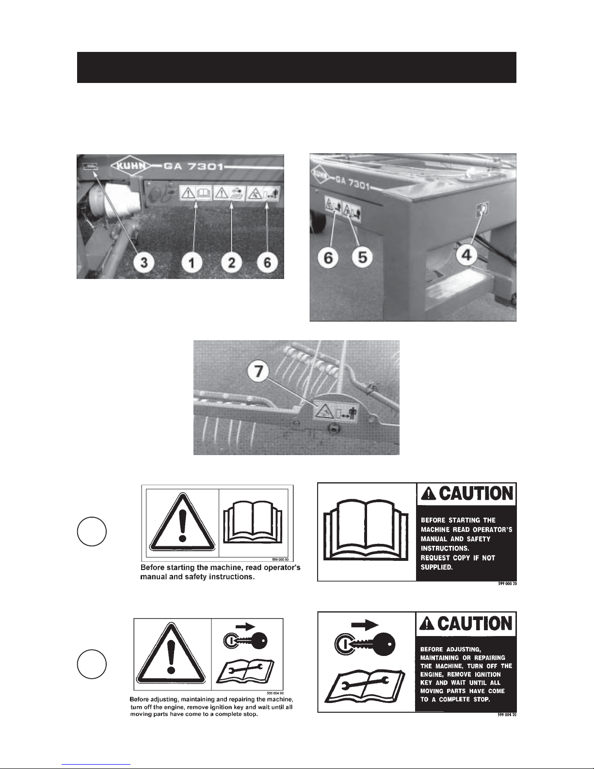
SAFETY DECALS
The following safety pictorials have been placed on your machine in the areas indicated. They
are intented for your personal safety and for the safety of the people working with you. The text
shown on them gives their precise meaning. Keep the pictorials clean. Replace them when they
are faded.
1
2
Page 11
- 9 -
3
4
5
7
6
Page 12

- 10 -
TECHNICAL SPECIFICATIONS
Technical specifications GA 7301
Tractor attachment Swivel hitch
Number of rotors 2
Number of tine arms per rotor 10
Working width 6,70-7,30 m (22'-24')
Swath width 1,40 to 1,80 (4'7"-6')
Transport width 2,50 m (8'2")
Transport height
- with disconnected tine arms
and folded guards 3,17 m (10'5")
- with tine arms and safety guards
in place 4,07 m (13'4")
Total length 5,40 m (17'8")
Forward speed up to 18km/h (11mph)
Work rate per hour up to 8ha (20 ac)
Power requirement 37 kW (50 hp)
Drive shafts (C.V)
- Primary PTO shaft without torque limiter
- Secondary PTO shafts with torque limiter
Total weight 1580 kg (3476 lbs)
Tyres/tyre pressure
- gyrorakes 16x6,5-8 (2 bars 29 PSI)
- carrying frame 10,0/80-12 (3 bars 43 PSI)
Hydraulic outlet required 1 x single acting outlet
Electric connection required 1 x 7 pin plug
Special note : On the GA 7301, guards can be folded down and tine arms disconnected in order to considerably
reduce the height of the machine in transport.
FITTING INSTRUCTIONS
A - MACHINES SHIPPED IN CRATES
On machines shipped in crates a certain number of
parts are disassembled. To assemble these parts,
proceed as follows :
1. Assembling guide wheels
Rest box section frame (P) on 2 trestles approximately 1 meter (3'3") high and fix securely to avoid
any movement.
Then bolt right hand and left hand wheel arms (A)
onto the box section frame (P) using 10 self-locking
screws (C) (M16 x 100), 10 spacers (X) (Ø 17 x 35
x 50) and 4 self-locking nuts (M16) (photo 1), but do
not tighten.
Page 13

- 11 -
Next assemble cross bar (D) using 4 self-locking
screws (E) (M 12 x 30) and 4 self-locking nuts (M 12)
(photo 2).
Now tighten bolts (C) in sequence (photo 1) on the
right hand side and the left hand side to a torque of 25
daNm / 185 ft-lbs. Then torque bolts (E) (photo 2) to
12 daNm / 90 ft-lbs. Re-tighten bolts (C) after a few
hours of use.
Fit the two wheels (R) onto the hubs by means of
wheel nuts (F), tighten to a torque of 15 daNm (110
ft.lbs) (photo 3). Make sure valves (V) are facing
outwards (photo 3).
Fit the two reflector supports (G) using 4 hexagonal
bolts (H) (M 8 x 30) and 4 self-locking nuts (M 8).
(Tightening torque 3 daNm / 22 ft-lbs) (photo 2).
Assemble triangular reflectors (I) on their supports
using 4 countersunk head screws (M 5 x 25) and 4
self-locking nuts (M 5) (photo 3).
2. Head stock assembly
Connect the pivoting head stock (K) to the box
section frame (P) using vertical axle (J). Secure axle
(J) with hexagon screw (L) (M 14 x 40) and selflocking nut (M 14) (Tighten to 14 daNm / 100ft-lbs).
Then drive in roll pins (M) (dia. 12 x 60 doubled with
7 x 60).
Lower the parking stand (N) to the vertical position
and lock into place with handle (Y) (photo 4).
Remove trestles to let the assembly rest on its wheels
(R) (photo 3) and parking stand (N) (photo 4).
Also assemble drive shaft cone guard (V) using 2
hexagon nuts (M 10) and 2 washers (11 x 24 x 2)
already on the machine (photo 4).
4
Page 14

- 12 -
3. Steering linkage system assembly
(Fig. 5)
Slide the short intermediate drag link (O) (length
1175 mm) into housings (Z) on carrying frame (P)
ensuring that the toggle is directed towards the
rear. Connect the long front drag link (Q) to trunion
(A) on the vertical axle (J) (fig. 5 and photo 9, page
13) and to the intermediate drag link (O).
Next assemble steering track rod (S) onto both
steering pivots (T) as shown in drawing 5. The
steering track rod is factory set to the theoretical
correct length. To check whether further adjustment
is required, proceed as follows :
Use a 5 m/16' long straight slat (U) to position the left
hand wheel parallel to the carrying frame (P). Wedge
wheel to avoid any change of direction.
Use a second slat (U1) to check that both wheels are
parallel. If necessary adjust rod length to achieve
correct wheel toe.
Without altering position of the wheels or carrying
frame, rotate the head stock (K) so that it is perfectly
perpendicular to the carrying frame (P).
Now adjust length of rod (W) to match the gap (X)
between both toggles and assemble in place. Tighten
counter nuts of rods (S) and (W) (drawing 5).
4. Assembly of lift arms and hydraulic
cylinders
Position the right and left lift arms (M) making sure
the rotor pivoting points are orientated towards the
rear (see fig. 24, page 17). Slide pins (N) into carrying
frame and lift arm bores adding shim washers (diameter 45 x 55 x 1) if necessary. Secure with roll pins (O)
(dia. 10 x 65).
Mount hydraulic cylinders (Q), locks (R) and spacers
(dia. 20x25x29) on the main frame using screws (F)
(M20x220) and self-locking nuts (M20). If necessary
add plain washers (dia.20x38x3) to align locks (R)
with studs (Y) (photo 6). Make sure the bolt heads
(F) are located on the lock side and tighten self-locking nuts moderately to ensure the good functioning
of locks (R). Fix the springs (T) and connect the cylinder rods to the rotor arm mounting yokes (M) with
pin (S) and 2 roll pins (V) (diameter 5 x 45) (photo
6).
Connect hydraulic hoses (U) to the hydraulic cylinders and attach them to their barrels with clamp collar
(W) (photo 6).
Slide the 3 flexible hoses (U) and (H) into eyelets (X)
fixed under the carrying frame (P) and connect to Tunion (D) (photo 7).
6
Page 15

- 13 -
Connect hydraulic hose (H) (photo 7) to the tractor
and activate hydraulics to lift arms (M) until they lock
automatically into the transport position (photo 8).
Install selector plates (L) with 6 self-locking screws
(F) (M 12 x 30) and adjust rod (T) for correct length.
Length is correct when locking pin of handle (E) is
approximately in the middle of one of the elongated
holes of selector plate (L) (photo 8) when the sliding
sections of the lift arms are completely slid into the
arms. Do not forget to tighten lock nuts (I) thereafter.
Then fit guard (B) using 5 hexagon screws (C) (M 8
x 100), 5 self-locking nuts (M 8) and 10 plain washers
(diameter 9 x 22 x 1.5) (place one washer under each
screw and the other under each nut). Make sure that
hoses (U) run through the cut-outs (V) provided in
guard (B) (photo 8A).
Now release hydraulic pressure to lower lift arms (M)
(photo 6).
NOTE : Before fitting guard (B) (photo 8A), do not
forget to set up the electric harness of light
and signal plates (see page 15).
5. Fixation of control cords
(photos 9 & 9A)
Pull one end of the 4500 mm (15') long cords (I)
through the eyelets (O), the rear side of lock holes
(R) and tie a knot at their front (photo 9).
Thread the other end of cords (I) through eyelet (6)
(photos 9 & 9 A).
Slightly tension cords so that they will not be trapped
by revolving rotor arms. Fix on a plastic washer and
tie a knot in front of eyelets (G) (viewed in forward
direction) (photos 9 & 9 A).
Now thread the free ends of the cords (I) through the
wooden handle (K) (photo 9 A) and tie knots at the
desired length so that locks can easily be maneuvered
from the tractor cab. Cut off surplus cord.
9
8
8A
Page 16

- 14 -
6. Assembly of rotors, caster wheels and
secondary PTO shafts
Assemble both right and left-hand rotors to pivoting pins
(L) of lift arms (M) so that the undercarriages (N) are
located in front of the rotor’s vertical axles (H) (seen in the
forward direction) (see figure 24). Secure the rotors with
retaining rings (T) (dia. 45 x 2.5) (photo 10). Do not forget
to install thrust washers (Y) (dia. 45 x 55 x 3) between
retaining rings (T) and plate (X) (photo 10).
Connect flexible hose (H) (photo 7) to the tractor hydraulic
outlet and slightly raise the rotors off the ground.
Slide the cylindrical hub protectors (01) onto axles (N)
until they seat on the axles' shoulders (fig. 11). Then slide
the conical grey protectors (02) onto the axles with the
conical side facing the wheel bearing locations (fig.
11).The grey protecting plugs are seated tightly on the
spindle’s shoulders. Drive them in place using a driver and
apply a blow with a hammer. Fill wheel caps (Q) with
grease. Also grease the space between both bearings
located inside the rims.
Install the 4 wheels (L) on axles (N). Insert conical spring
washer (O) (convex side against nut) and fit low self
locking nut (P) (M 16 x 1.5). Tighten to 12 daNm / 88 ft.lbs.
Fit wheel caps (Q) in place (figure 11).
Note : GA 7301 USA are equipped as standard with
bogie axles. To install them, refer to page 27.
Mount cone guard (R) on the rotor side, using clamp
collars and cone guards (R 1) on the bevel gearbox side
using 2 hexagon screws (M 8 x 16) and 2 flat washers
(diameter 9 x 22 x 1,5) (photo 12).
Mount secondary PTO shafts (S) positioning the torque
limiter on the rotor side and the CV joint on the bevel
gearbox side. Before connecting the PTO shafts, it is
necessary to position the rotors so that tine arms operate
symetrically in relation to one another. Connect safety
chains (U and U1) as shown on photo 12.
7. Assembly of reflector boards
Mount the left and the right reflector supports (A) on both
sides of the frame (P) using 4 hexagon screws (C)
(M12x70), 4 flat washers (diameter 13 x 35 x 5) and 4 selflocking nuts (M12) (Torque 10 daNm / 75 ft-lbs) (photo 13),
in such a way that the side guards (H) can be folded back
in transport position (see photo 43 on page 25).
Fix reflector boards (D) onto supports (A) using 6 hexagon
screws (H) (M 10 x 25) and 6 self locking nuts (photo 13).
Stick the 2 white reflectors (V) on the lower outside
corners of the front reflector boards (D) (see photo 15).
Fit rear reflector board holders (A') to wheel legs (S) with
4 hexagon bolts (C’) (M12 x 70), 4 flat washers (diameter
13 x 35 x 5) and 4 self-locking nuts (M12). Tighten to 10
daN.m/75 ft.lbs (photo 14).
Now assemble rear reflector boards (D’) to the plates (B)
and to their holders (A’) with 4 hexagonal bolts (F)
(M 10 x 25), 8 hexagonal bolts (E) (M 10 x 60) and 12 selflocking nuts (M 10) as shown in photo 14.
11
13
Page 17

- 15 -
8. Fitting warning lights
Fit front lights (K) to signal plates (D) (photo 15).
Fit rear left light onto the rear left signal plate. The left rear light can be recognized by an inscription "L" and a white
mark on the connector.
Fit rear right light (I) marked “R” onto the rear right signal plate (D’) (photo 14).
Before fitting guard (L) (see page 13), thread the electric harness inside guard (L) through eylets (X) (photo 7).
Then thread cables (M) for the front light through flexible rings (N) and attach them to the front signal plate holders
(A) with 4 clamp collars (O) (length 350 mm/14") (photo 13).
Now route cables (D) for the rear lights of guard (L) and attach them to frame (P) and to wheel arms (Q) with 2
clamp collars (R) (length 508 mm/20") and 6 clamp collars (T) (length 350 mm/14") (photos 16 and 17).
Note : Harness connectors are identified as follows :
- Connector for rear left light has an inscription "L" and a white mark (in grey on figure 18).
- Connector for rear right light is marked “R”.
To complete the job, plug the harness connectors to the corresponding front and rear lights.The locking tab (1)
of the female connector (2) must be fully engaged over the peg (3) of the male connector (4) (fig.18).
Attach front end of electrical harness to hydraulic hose with 3 clamp collars (S) (length 176 mm/7") (photo 19).
14 15
19
18
16
17
Page 18

- 16 -
9. Safety guard assembly
Attach hinges (W) to supports (X) using 4 hexagon
screws (I) (M12 x 35) and 4 self-locking nuts (M12)
(Torque = 10 daN.m/75 ft.lbs) (photo 20).
Mount folding guards (Z) to hinges (W) with roll pins
(O) (dia. 8 x 55) (photo 20) and (O') (dia. 8 x 55)
(photo 21). Do not forget to insert spacer washer (R)
(dia. 40 x 51 x 7) between roll pins (O) and hinges (W)
(photo 20).
When mounting the foldable guards
(Z), make sure the lock rods (T) are
located underneath the safety guard
when in working position (photo
21).
Install the 4 clips (C) on side beams (W) by means
of 4 hexagonal screws (M 8 x 55) and 4 self-locking
nuts (M 8) using the handles (K) as templates.
Then mount inner safety guards (D) to hinges (W)
using 2 hexagon screws (E) (M 10 x 60). Do not
forget to insert conical spring washers on both sides
of safety guard tubing (photo 21).
After assembly, make sure each
safety guard locking system works
correctly.
10. Fitting tine arms and tines
First fit tine arms (E) to supports (S) and secure
using linch pins (U) (fig. 22).
Connect the small hook of safety strap (X) to linch pin
(U), then connect the large safety strap hook to the
hole (A) of bracket (W) on tine arm (E) (fig. 22).
Next fit the supports (S) with tine arms on the
oscillating shafts (L) using roll pins (V) (dia.12 x 55
and 7 x 55) (fig. 22A).
The right and left-hand rotor arms are symetrically
curved to one another. Ensure they are positioned so that the curved portion is facing the
front as seen in the direction of rotation (see
arrows figure 23) and the flattened side of the
tine arms must always be positioned on the top
side.
ATTENTION : Make sure slots of roll pins are ori-
entated opposite to one another and
in the direction of main effort (see
drawing on figure 23).
Clean and apply regularly a «NeverSeize» compound to the detachable
tine arm ends (E) (fig. 22) (see also
page 26).
22A
22
Page 19

- 17 -
The tines (A) must be attached underneath the tine
arms (E) so that their fingers are slanting away from
the direction of rotation (see arrow).
The tines are secured to the arms by using the screw
(B) (M12 x 75), the self-locking nut (G) (M12), the
washer (C) (diameter 13 x 35 x 5), the spring washer
(F) and the tine bracket (D).
Make sure that the parts are assembled correctly as
shown in figure 24.
11. Rotor horizontality (photo 25)
Once the tine arms and tines have been installed on
the rotors, proceed as follows to adjust rotor
horizontality :
- Lift the machine’s headstock until the main frame
is horizontal, or attach machine to a tractor and lift
the draft arms until the hitch pins are at a distance
of 600 mm / 2’ above ground level (see page 20)
- Place the machine on a flat surface with the 2 rotors
lowered on the ground. Adjust wheel height of the
left and right rotors to level them sideways.
- Check that the rotors are level in the direction of
travel. If they are not level, proceed as follows:
- Slightly loosen the 4 mounting screws (M) of the
first rotor.
- Level the rotor in direction of travel by rotating
eccentric (P) using a 36mm wrench (Q) or an
adjustable wrench. Tighten the 4 mounting screws
(M) and torque them to 14 daN.m / 103ft.lbs
- Proceed in the same way to level the second rotor.
24
25
Page 20

- 18 -
12. Assembling of central swath
screen
Mount swath screen support (D) to the central gearbox
(E) with 4 hexagon bolts (M 12 x 25) and 2 plates which
must be installed under the bolt heads (photo 26).
Connect crank (F) to crossbar (H) using support (G),
2 hexagon bolts (I) (M 12 x 18) and 2 self-locking nuts
(M 12). Make sure the end portion of the crank with
drive pin (J) is housed by the screen tube as shown in
photo 26.
Assemble the SMV mounting bracket (S) on support
(G) with 2 self-locking screws (T) (M 8 x 12) and 2 selflocking nuts (M 8) (photo 26).
B. MACHINES SHIPPED “PREASSEMBLED”
The unloading operation of a GA 7301 that has been shipped in a “preassembled” form requires a lift mechanism
(crane, hoist etc.) with a minimum capacity of 2 tons.
Connect lifting hooks (K) to the 4 anchorage points (L) located on the main carrying frame (M) and to the
hydraulic cylinder mounting yokes (N) (photos A and B).
The 4 anchorage points (L) are indicated by the opposite decal.
Keep all persons away from the danger zone whilst unloading the machine.
26
Page 21

- 19 -
Use the 2 textile slings (O and P) (photo C), working
out their length so that the machine is lifted up
horizontally (minimum capacity of 1500 kg on both
strands of each sling when these slings are of the
length indicated in photo C).
Before starting to assemble the unit, carefully remove
braces (Q) and (R) as well as all connecting wires
(photo D) which will no longer be of use.
All loose components (tine arms, tines, PTO shafts,
signalling elements and hardware bags) are packed
onto a separate pallet.
All fitting instructions for GA 7301 gyrorakes shipped in crates also apply to the
“preassembled” units.
D
Page 22

- 20 -
ATTACHMENT
1) FITTING TO THE TRACTOR
The GA 7301 Gyrorake can be fitted to all tractors with a standard three-point linkage Cat. 2 and a power included
between 60 and 90 hp (45 and 67 kW).
The swivel hitch is equipped with two attachment yokes (C) to be connected to the tractor lower links (T) (photo 27).
Attachment should always be made within yokes (C). Two bushes diameter 37 are supplied with the machine for
attachment to Cat. 3 tractors.
Raise the tractor hydraulic linkage until the swivel head lower links clear the ground by approx. 700 mm / 2' 6".
Attach one end of chains (R) to hitch brackets (C) with D-hangers (M) and their other end to the tractor top link
pin (O) (photo 27).
Completely lower the tractor linkage. Height adjustment is correct when :
. lower link arms (T) are level,
. chains (R) are tight,
. distance (A) between hitch pins and ground is 600 mm / 2' (photo 27).
Always make sure the tractor lower links are immobilized using the means provided (check chains, etc...).
Connect hydraulic hose (F) and plug (H) of the light and signal system (photo 27). To do this a female hydraulic
connection and a 7-pin electric socket at the rear of the tractor are required (photo 27).
Activate the tractor 3-point lift to slightly raise the machine's head stock.
Fold parking stand (D) upwards until it is automatically locked in the horizontal position by handle (P) (photo 27).
27
Page 23

- 21 -
2) PTO SHAFT
Connect the PTO shaft to the 540 rpm (min-1) tractor drive (with the wide angle on the machine side).
Make sure PTO length is correct :
1) When the PTO is in its maximum extended position, a minimum tube overlap of 300 mm (12") must be maintained.
2 ) When the PTO is in its maximum overlap position (retracted), tubes must not butt against the yokes. As a safety
measure a clearance of at least 2 cm (0.8") must be maintained. If this is not the case, shorten the two transmission
tubes and the two guard tubes by the same length (photos 28 and 29). Bevel and clean the tubes (photo 30) and
grease the inside of the outer tube (photo 31).
3) Never operate the PTO at too great an angle (30° maximum)
These recommendations and adjustments must be respected to avoid damage or premature
wear of the PTO.
Never connect the PTO to the 750 or 1000 rpm (min-1) tractor drive.
To avoid accidents which could be serious, make sure that the guards are always correctly
in place and secured with the safety chains provided (photo 27). Worn or damaged guards
must be replaced immediately.
Page 24

- 22 -
WORKING POSITION AND ADJUSTMENTS
The GA 7301 raking width can be set in 4 different
positions from 6.70 m / 22' to 7.30 m / 24'. Adjustment
is carried out as follows :
- With the machine in transport position (rotors lifted),
select working width by locking rods (T) in one of the
4 elongated holes (O) of the selector plates (L)
(photo 32).
- The machine can now be lowered into working
position.
NOTE : Make sure rods (T) are positioned in the
same elongated hole number on each rotor.
To fold the machine into working position, proceed as
follows :
- Pivot side guards (H) under reflector board supports
(A) and lock into place with linch pins (J) (photo 33).
- Pull control cords (I) (photo 9 A) accessible from the
tractor cab to unlock cylinders (photo 34) and lower
rotors.
- Attach tine arms to their respective rotors (see page
16).
- Insert handles (K) through hole in lock rods, release
the foldable guards (Z) and lower them in working
position (see arrow, photo 34).
- Return handles (K) in their storage location (C)
(photo 34).
Always maintain the tractor hydraulic valve in the free floating position
during work.
Make sure there is nobody in the
machine operating area before lowering the rotors into their working
position.
Make sure that the sliding sections (E)
of the telescoping lift arms (F) slide
freely and have the right amount of
play when folding the machine from
transport to working positions and
vice versa. To adjust play, tighten
bolts (G) until there is no play, then
untighten them half a turn (photo 35).
Tighten lock nuts (I) after adjustment
(photo 35).
NOTE : To avoid any risk of jamming regularly grease
the sliding parts of the lift arms with SHELL
Multi-Purpose grease NLGI grade 2.
Page 25

- 23 -
Wheel height adjustment :
The left and right wheels must be adjusted so that the
rotors are level.
The height of the GA 7301 is correct when the
tines slightly skim the ground while the rotors are
in the horizontal position (see “rotor horizontality”,
page 17).
The adjusting system for the wheel height consists
of :
- a vertical sector (A) with 7 holes,
- a pin operated by the lever (B) (photo 36).
Central swath screen
To lower or raise swath screen (C), free crank (F) by
pulling out linch pin (A) (diameter 8) and rotate crank in
one or the other direction (photo 39). Lock again crank
(F) with support (G) using linch pin (A) when correct
screen height has been selected.
The housing of the axle (D) has on its outer side four
notches which correspond to the holes 1, 3, 5 and 7
of the sector (A). The three spaces between the
notches correspond to the holes 2, 4 and 6 (photo 37).
The roll pin (C) is used as a marker for the height
adjustment of the wheels (fig. 37). Initially, it is
recommended to engage the pin in the fifth hole of
the sector (A).
Height adjustment of the wheels is carried out as
follows :
- Raise the rotors until the axles (Y) are butting
against the pawls (R) (photo 6, page 12).
- Free the pin of the vertical sector (A) by pushing the
lever (B) away from the wheel and in the direction
of the arrow (photo 38).
- Raise or lower each wheel by one or more holes
(positions 1 to 7, photo 37).
- Lower the rotors on the ground.
Note :After each wheel height adjustment, make
sure that the pin is fully engaged in its
housing in the vertical sector.
Note : To adjust the wheel height on the bogie
axles on GA 7301 USA, refer to page 27.
39
Page 26

- 24 -
OPERATION
FORWARD SPEED
Forward speed must be determined in accordance with quantity of crop, type of terrain, etc. It is recommended to
always operate at a lower speed when working in difficult conditions, however it is not possible to recommend specific
speeds, these must be determined by the operator under the prevailing conditions.
The GA 7301 must not be operated using a PTO
speed (PTO rotational frequency) above 540 rpm
(min-1) (see figure opposite).
The GA 7301 forms a central swath. At the edges of
fields, it is possible to lift the rotors slightly.
The machine can also form a swath using one rotor
only, either right or left.
To do this, lock one rotor into the transport position,
disconnect driveline from bevel gearbox and attach
it on support (S) on the carrying frame (photo 40).
When working with one rotor only or when working
with both rotors in very light and short stemmed crop,
the swath form is improved by lowering the central
swath screen (C) (see photo 39, page 23).
To avoid accidents, it is forbidden to let the rotors rotate in the vertical position.
40
Page 27

- 25 -
TRANSPORT
To fold the machine into transport position, proceed as
follows :
- Unlock the foldable guards (Z) using handles (K) and
raise them in transport position (see arrow, photo
41).
- Return handles (K) in their storage location (C)
(photo 41).
- Disconnect the 3 outside tine arms (E) of each rotor
and place them into the two racks (R) (photo 41 A).
Secure tine arms with linch pins (S) (photo 41 A).
- Pull the control cords (I) (photo 9A) and activate the
tractor hydraulics to lift the 2 rotors until they lock
automatically into the transport position (photo 42).
- Fold back side guards (H) and lock them in place
with linch pin (J) (photo 43).
- Wind up swath screen (C) (photo 43) (also see page
23).
- Check that plug (H) of the light and signal system is
properly connected (see photo 27 on page 18) and
ensure that all signal lights are functioning correctly.
Wait until the rotating elements have
come to a complete stop and keep all
persons away from the vicinity of the
machine before pivoting the rotors
into work or transport position.
When working on slopes, turn the
whole unit, tractor-machine, in the
direction of the slope before
unfolding the rotors.
The parking stand must always be
lifted when in transport and in work.
Never engage the rotor drive when
the machine is in the transport position.
Do not tow the GA 7301 at a speed
exceeding the limits in force in the
country in which the machine is
transported. If in doubt about the legal
speed limit, consult a legal adviser.
42
Page 28

- 26 -
PARKING THE MACHINE
The GA 7301 is equipped with a parking stand (N) to
park the machine in work or transport position.
To park the machine proceed as follows :
- Lower parking stand (N) to vertical position until it is
automatically locked in place by handle (P) (photo
44).
- Lower the tractor 3-point linkage till machine rests on
the parking stand (N).
- Disconnect machine from tractor.
- Place PTO shaft (T) in the PTO support (C) on the
hitch (photo 44).
- Put light and signal plug (F) and male coupling (M)
of the hydraulic hose into their parking supports
(photo 44).
- Fold back side guards (H) and lock them in place
with linch pin (J) (photo 43).
Always park the machine on an area
where the ground is even and fairly
level.
NOTE : The GA 3701 are delivered with a set of 2
wheel sprags (3) (no. 114 6330) which are to
be placed under the carrying frame wheels
when the machine is parked.
Attach holders (1) to the front of the rear
warning board supports (2) with 8 hexagonal
bolts (4) (M 8 x 16) and 8 self locking nuts
(M 8) as shown in photo opposite.
LUBRICATION
Grease the following with SHELL Multi-Purpose grease NLGI grade 2 :
- Every 8 hours of use and at the end of each season : yokes, bearings and drive tubes of the 3 PTO shafts.
- Once a week : rotor housings, tine arm bushings, wheel axle supports and transmission U-joints, pivoting head
stock, guide wheels, steering linkage, pivoting arms and their sliding sections.
Regularly clean and apply a «Never-seize» compound to the removable portion of the tine arms to ensure easy
removal (see fig. 22 on page 16).
Lubricate the following with SHELL X 100 or SAE 90 EP oil :
- As required : hydraulic cylinder articulations, folding safety guard locks, working width adjustable rods.
- Once a year : check oil level in bevel gearbox (capacity 0.65 litres / 1.14 pints).
TO ENSURE TROUBLE FREE OPERATION OF YOUR MACHINE,
WE RECOMMEND SHELL LUBRICANTS.
44
Page 29

- 27 -
To adjust bogie axle height, proceed as follows :
- Raise the rotors with the tractor hydraulics until axles (Y) are butting against the pawls (R) (photo 6, page 12).
- Remove linch pin (8) and pull wheel axles (9) away from the machine to free pins (5) (fig. 46)
- Position wheel axles (9) at the desired height and fully engage pins (5) in the corresponding vertical sector (12)
hole (fig. 46).
- Secure wheel axles (9) by reinserting linch pins (8) in place (fig. 46).
Always ensure that both bogie axles (right and left side) are adjusted to the same height.
1. BOGIE AXLE KIT (2 x No 113 6180) ) (standard equipment on GA 7301 USA)
This equipment is recommended for improved floatation when operating on irregular grounds. It helps stabilising
the machine at high speed thereby reducing the load placed on structural components.
To attach bogie axle, proceed as follows :
- First remove both wheels (F) then both vertical
sectors (A) both levers (B) and both pins (E) from
the standard wheel column support (10) (photo
45).
- Fit new pins (5) supplied with the kit onto the
machine's vertical sector supports (3) using plain
washers (2) (diameter 13 x 30 x 4) and self-locking
nuts (1) (M 12) (fig. 46).
- Replace standard grease zerks (G) (photo 45) by
2 curved grease zerks (4) (fig. 46).
- Install pre-assembled left and right (9) wheel axles
onto vertical sector supports (3) and secure with
cotter pins (6) (diameter 8 x 63) (fig. 46).
- Install linch pin (8) (diameter 10 x 60) and attach to
cotter pins (6) with PVC cords (7) (fig. 46).
- To finish the job, fit both standard wheels (F) (photo
45) onto axle spindles (11) (fig. 46) respecting their
original position. Do not forget to pack wheel caps
and the space between both bearings located inside
the rims with grease.
OPTIONAL EQUIPMENT
46
45
Page 30

- 28 -
2. 3D - SUSPENSION KIT (No. 114 6400)
The 3D - suspension kit provides an additional degree of freedom to the rotors. Under the support of a third wheel,
the rotor pitch angle is adapted to the ondulations of the terrain. The result is a better raking quality and greater
crop yields when working in uneven conditions.
To fit the 3D - suspension kit, refer to instructions no 078 174 11 supplied with the kit.
3. PTO SHAFT WITH FREE-WHEEL (No. 4600 238)
This PTO shaft is available as an optional extra.
4. EQUIPMENT "BOGIE AXLE WITH 8 WHEELS USA" (No. 114 6550)
This equipment is recommended for improved floatation when operating on irregular grounds. It helps stabilising
the machine at high speed thereby reducing the load placed on structural components.
To fit this kit, refer to instructions no L8008020 supplied with the kit.
Page 31

- 29 -
ELECTRICAL CONNECTOR (for North America)
KUHN wiring harnesses are supplied with an ISO (International Standards Organization) 1724 plug connector .If
the implement is to be operated with a tractor equipped with an SAE style seven-pin connector a SA J 560b
plug must be installed. If required, the SAE J 560b plug is factory supplied with the machine.
Implement wiring harness description
Colors Function Terminal connection
ISO 1724 plug SAE J 560b plug
White Ground 3 1
Black Left running lights 7 6 *
Yellow Left turn & hazard 1 3
Red Stop lights 6 4 **
Green Right turn & hazard 4 5
Brown Right running lights 5 6 *
Blue Not used 2 7
* Note that the black and brown wires must be connected together on SAE type connectors for proper light
opération.
** The red wire should only be attached to the #4 terminal if the #4 terminal on the tractor is confirmed to be
a brake light terminal. If the tractor has no brake terminal the red wire of the implement should be sealed
off and not connected to any terminal.
Page 32

- 30 -
SOUND LEVELS
Sound levels given out by : GA 7301
Sound levels have been measured in accordance with the measuring methods as defined in:
EN 1553
<< Agricultural machinery - Agricultural self-propelled, mounted, semi-mounted and trailed machines -
Common safety requirements >>
A-weighted emission sound pressure level L (A) eq inside tractor cab (with closed windows) :
Tractor only : 78.0 dB (A)
Tractor + machine : 76.0 db (A)
Page 33

LIMITED WARRANTY
KUHN S.A. of 4 Impasse des Fabriques, 67706 SAVERNE CEDEX, France (hereinafter called the
«Company») warrants, in accordance with the provisions below, to each original retail purchaser of
KUHN new equipment of its own manufacture, from an authorized KUHN dealer, that such equipment
is, at the time of delivery to such purchaser, free from defects in material and workmanship and that
such equipment will be warranted for a period of one year starting from the date the goods are delivered
to the end user and during this period up to a limit of 500 hours use, providing the machine is used and
serviced in accordance with the recommendations in the Operator’s Manual.
THESE CONDITIONS ARE SUBJECT TO THE FOLLOWING EXCEPTIONS :
1. Parts of machines which are not of our manufacture i.e. tyres, belts, P.T.O. shafts, clutches etc., are not
covered by this Limited Warranty but are subject to the warranty of the original manufacturer. Any claim
falling into this category will be taken up with the manufacturer concerned.
2. Warranty claims applying to these types of parts must be handled in the same way as if they were parts
manufactured by KUHN. However, compensation will be paid in accordance with the warranty agreement of the manufacturer concerned in as much as the latter justifies such a claim.
3. This Limited Warranty will be withdrawn if any equipment has been used for purposes other than for
which it was intended or if it has been misused, neglected or damaged by accident or let out on hire. Nor
can claims be accepted if parts other than those manufactured by us have been incorporated in any of
our equipment. Furthermore, the Company shall not be responsible for damage in transit or handling by
any common carrier and under no circumstances within or without the warranty period will the Company
be liable for damages for loss of use or damages resulting from delay or any consequential damage.
We cannot be held responsible for loss of earnings caused by a breakdown or for injuries either to the owner
or to a third party, nor can we be called upon to be responsible for labor charges, other than originally
agreed, incurred in the removal or replacements of components.
THE CUSTOMER WILL BE RESPONSIBLE FOR AND BEAR THE COSTS OF:
1. Normal maintenance such as greasing, maintenance of oil levels, minor adjustments, etc.
2. Transportation of any kind of any KUHN product to and from the place the warranty work is performed.
3. Dealer travel time to and from the machine or to deliver and return the machine from the workshop for
repair.
4. Dealer travelling costs.
Parts defined as normal wearing items are listed as follows and are not in any way covered under this
Limited Warranty :
V belts, discs, knives, wear plates, disc guards, tires, torque limiters, hydraulic hoses, pitman shafts, swath
sticks, blades, tines and tine holders.
KUHN Limited Warranty will not apply to any product which is altered or modified without the expressed
permission of the Company and/or repaired by anyone other than Authorized Service Distributors or
Authorized Service Dealers.
Page 34

LIMITED WARRANTY IS DEPENDENT UPON THE STRICT OBSERVANCE BY THE
PURCHASER OF THE FOLLOWING PROVISIONS :
- That this Limited Warranty shall not be assigned or transferred to anyone unless the Company’s consent in
writing has first been obtained.
- The warranty/product registration form has been correctly completed by dealer and purchaser with their
names and addresses, dated, signed and returned to the appropriate address as given on the warranty/
product registration form.
- The claim form sent to KUHN has been correctly completed stating:
* dealer’s name and address
* owner’s name and address
* type of machine
* machine serial number
* delivery date to buyer
* date of failure
* tractor make and type
* description of the failure and its cause
* quantity, reference number and name of the damaged parts
* reference number , quantity and date of the invoice for the replacement parts .
- The judgement of the Company in all cases of claims under this Limited Warranty shall be final and conclu-
sive and the purchaser agrees to accept its decisions on all questions as to defect and to the exchange of
any part or parts.
- That all safety instructions in the Operator’s Manual shall be followed and all safety guards regularly inspected
and replaced where necessary .
No warranty is given on second-hand products and none is to be implied. Persons dealing in the Company’s
products are in no way legal agents of the Company and have no right or authority to assume any obligation
on their behalf, express implied, or to bind them in any way .
KUHN S.A. reserves the right to incorporate any change in design in its products without obligation to make
such changes on units previously manufactured.
Moreover, because of the constant progress in technology, no guarantee is given to the descriptions of
equipment published in any document by the company .
DISCLAIMER OF FURTHER W ARRANTY
There are no warranties, expressed or implied, except as set forth above. There is no
warranty of merchantability. There are no warranties which extend beyond the description
of the product contained herein. In no event shall the company be liable for indirect, special
or consequential damages (such as loss of anticipated profits) in connection with the retail
purchaser’s use of the product.
Page 35

This machine complies with the safety requirements of the European machinery directive.
The Operator should respect all Health and Safety regulations as well as the Highway
Code. For your own safety, use only genuine KUHN spare parts. The manufacturer
disclaims all responsibilities due to incorrect use or non-compliance with the
recommendations given in this manual.
Page 36

Printed in France by KUHN
KUHN S.A. 4 Impasse des Fabriques F - 67706 SAVERNE CEDEX (FRANCE)
Tél. : + 33 (0) 3 88 01 81 00 - Fax : + 33 (0) 3 88 01 81 03
www.kuhnsa.com - E-mail : info@kuhnsa.com
Société Anonyme au Capital de 19 488 000 Euros
For your safety
and to get the best from your machine,
use only genuine KUHN parts
 Loading...