

Page 1

OPERATOR'S MANUAL
KN143BGB E
Gyrorake
GA4521GTH
KN143BGB E
- English - 11-2009
Page 2

Page 3

Gyrorake
GA4521GTH
$Dear Owner
In buying a Kuhn machine you have chosen wisely. Into it have gone years of thought, research and
improvement. You will find, as have thousands of owners all over the world, that you have the best that
engineering skill and actual field testing can produce. You have purchased a dependable machine, but only
through proper care and operation can you expect to receive the performance and long service built into it.
This manual contains all the necessary information for you to receive full efficiency from your machine. The
performance you get from this machine is largely dependent on how well you read and understand th is manual
and apply this knowledge. Please DO NOT ASSUME YOU KNOW HOW TO OPERATE AND MAINTAIN YOUR
MACHINE before reading this manual carefully. KEEP THIS MANUAL AVAILABLE FOR REFERENCE. Pass
it on to the next owner if you re-sell the machine.
Your KUHN dealer can offer a complete line of genuine KUHN service parts. These parts ar e manufactured and
carefully inspected in the same factory that builds the machine to assure high quality and accurate fitting of any
necessary replacements.
About improvements
We are continually striving to improve our products. It therefore reserves the right to make improvements or
changes when it becomes practical to do so, without incurring any obligations to make changes or additions to
the equipment sold previously.
Designated use of the machine
The GA4521GTH Gyrorake must only be used for the work for which it has been designed: raking on the gro und
and forming windrows of pre-mowed fodder and straw.
Document illustrations
The illustrations in this manual may be based on one typ e of machine only. However, all instructions apply to all
machines covered in this manual .
Dear Owner
1
Page 4

Gyrorake
GA4521GTH
$Contents
Dear Owner.....................................................................................................................1
Contents..........................................................................................................................2
Identification of the machine.........................................................................................4
Front view (working position) .........................................................................................................4
Rear view (working position)...........................................................................................................4
Model identification plate ................................................................................................................5
Optional equipment..........................................................................................................................5
Safety...............................................................................................................................6
Description of symbols used in this document.............................................................................6
Safety instructions...........................................................................................................................7
Location and description of safety decals on the machine .......................................................15
Road safety equipment and recommendations...........................................................................18
Machine specifications................................................................................................19
Description and glossary...............................................................................................................19
Technical specifications............. ... ... ... .... ... ... ... ... .... ............................................. ... ... .... ... ............20
Sound levels ......... ... ... .... ... ... ... .... ............................................. ......................................................20
Putting into service......................................................................................................21
Coupling and uncoupling..............................................................................................................21
Instructions for transport............................................................................................28
Putting the machine into transport position................................................................................28
2
Conformity with the road regulations...........................................................................................31
Contents
Page 5

Gyrorake
GA4521GTH
Instructions for work...................................................................................................32
Putting the machine into work position............. ..........................................................................32
Adjustments in working position..................................................................................................34
Machine use....................................................................................................................................37
Optional equipment.....................................................................................................38
Safety chain....................................... ... ... ... .... ... ... .......................................... ... .... ... ... ...................38
Prop wheel......................................................................................................................................40
Hydraulic windrow curtain ............................................................................................................41
Maintenance and storage............................................................................................ 48
Frequency chart .............................................................................................................................48
Lubrication............................................................................................ ..........................................49
Maintenance....................................................................................................................................52
Storage............................................................................................................................................52
Trouble shooting guide...............................................................................................53
Limited warranty.......................................................................................................... 54
Contents
3
Page 6
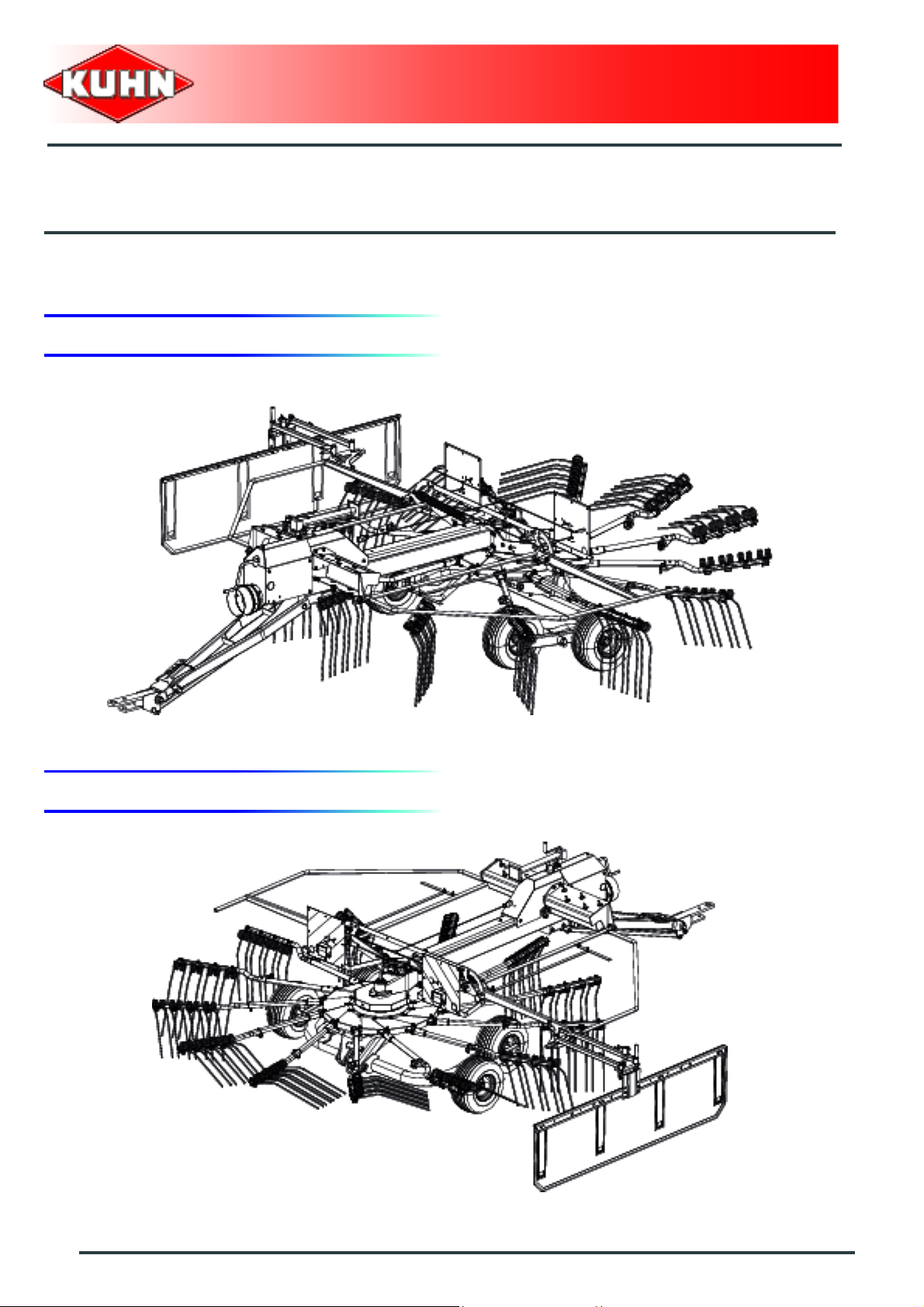
$Identification of the machine
1. Front view (working position)
Gyrorake
GA4521GTH
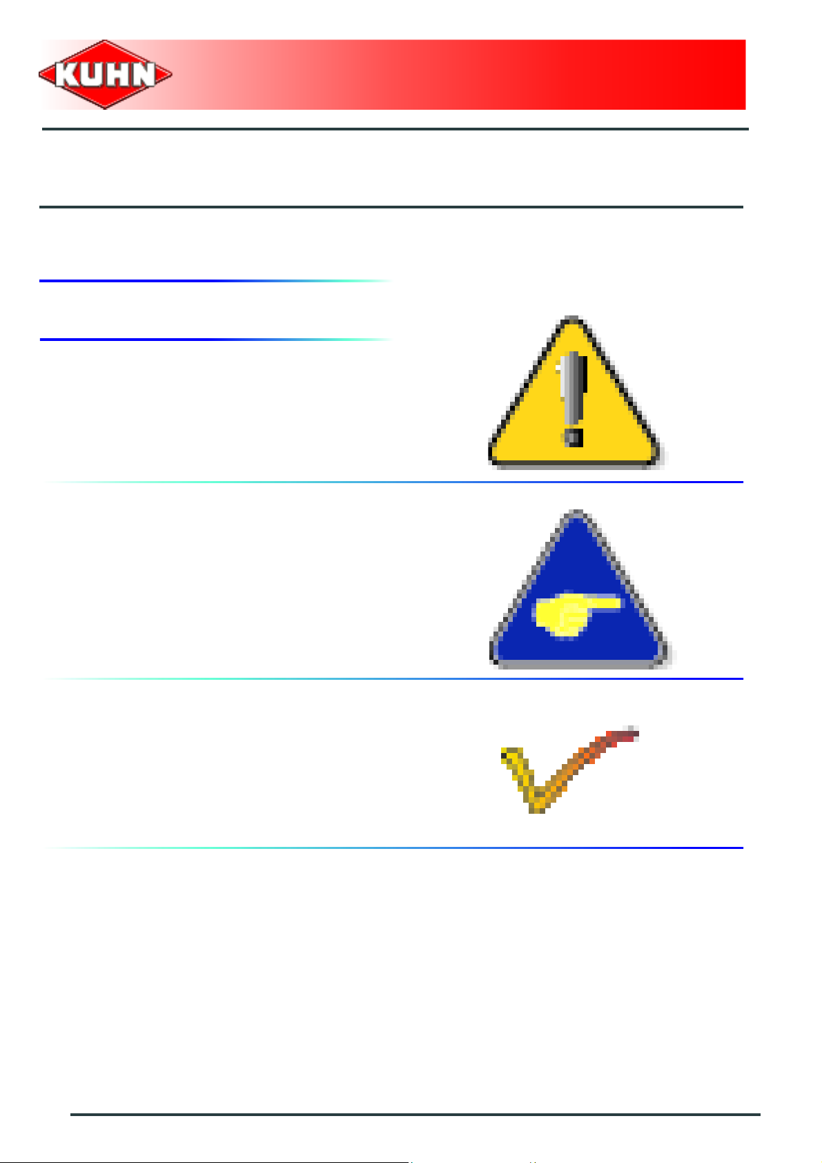
2. Rear view (working position)
4
Identification of the machine
Page 7

3. Model identification plate
Please write below the type and serial number of the
machine. This information is to be indicated to the dealer
for all spare parts orders.
Gyrorake
GA4521GTH
Type: GA4521GTH
Serial no.:
4. Optional equipment
Tick box corresponding to the equipment fitted on your
machine:
Kit no. 1116860: Safety chain (ANSI/ASAE : 45 kN (10100 lbf)).
Kit no. 1146600: Prop wheel.
Kit no. 1136420: Hydraulic windrow curtain.
Identification of the machine
5
Page 8
$Safety
1. Description of symbols used in this document
This symbol indicates a potentially hazardous situation
that if not avoided, could result in serious bodily injury.
Gyrorake
GA4521GTH
This symbol is used to identify special instructions or
procedures which, if not followed strictly, could result in
machinery damage.
This symbol is used to communicate technical
information of particular interest.
6
Safety
Page 9
Gyrorake
GA4521GTH
2. Safety instructions
Introduction
The machine must only be operated, maintained and repaired by competent persons who are familiar with
machines' specifications and operation and aware of safety regulations fo r preventing accidents.
The operator must imperatively respect safety instructions in this manual and in the warnings posted on the
machine. The operator is also obliged to respect current le gislation concerning accident prevention, wo rk safety
and public traffic circulation.
Designated use of the machine also means following operation, maintenance and repair recommendations
given by the manufacturer, and using only genuine spare parts, equipment a nd acce sso ries, as r ecom mended
by the manufacturer.
The manufacturer is not held liable for any damage resulting from machine applications other than those
specified by the manufacturer. Any use other than the designated operation is at the risk and responsibility of
the operator.
The manufacturer is not held liable for any damage or accident re sulting from machine modifications carried out
by the operator himself or by a third party without previous written agreement from the manufacturer.
Read and follow the safety instructions
Before using the machine, carefully read all the safety
instructions in this manual and the warnings placed on
the machine.
Before starting work, the operator must be familiar with
all machine controls, handling devices and their
functions. It is too late to learn once work has been
started!
Never let anyone operate the machine who is not traine d
to do so.
Should you have any difficulties in understanding certain
parts in this manual, please contact your KUHN dealer.
Precautions to be taken before carrying out
any operations on the machine
Before leaving the tractor or before adjusting,
maintaining or repairing the machine, disengage the
PTO drive, turn off the engine, remove ignition key and
wait until all moving parts have come to a complete stop
and apply park brake.
Safety
7
Page 10
Precautions to take before using the
machine
Do not wear loose clothing which could become caught
up in moving parts.
Wear the appropriate protective clothing for the work in
hand (gloves, shoes, goggles, helmet, ear defenders,
etc.).
Ensure that all operating controls (ropes, cables, rods,
etc) are placed so as they cannot be operated
unintentionally and cause damage or injury.
Before operating the machine, check tightness of nuts
and bolts, particularly on fixing elements (tines, forks,
blades, knives, etc). Retighten if necessary.
Before operating the machine, ensure that all the safety
guards are firmly in place and in good condition.
Immediately replace any worn or damaged guard.
Gyrorake
GA4521GTH
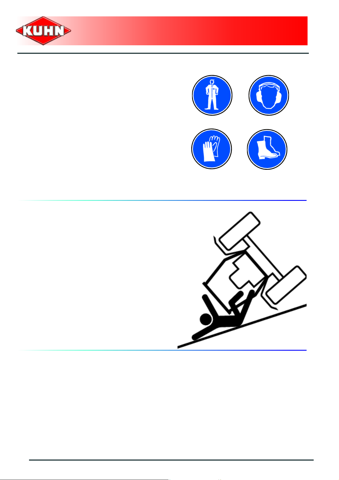
Precautions when driving
Tractor handling, stability, performance and braking
efficiency are all affected by weight distribution, trailed or
mounted implements, additional ballast and driving
conditions. It is therefore of great importance that the
operator exercises caution in every given situation.
Groundspeed must be adapted to ground conditions as
well as to roads and paths. Always avoid abrupt change s
of direction.
Be particularly cautious when turning corners, paying
attention to machine overhang, length, height and
weight.
Never use a narrow track tractor on very uneven or
steeply sloping ground.
Never leave the tractor seat while the machine is
operating.
Carrying people or animals on the machine when
working or in transport is strictly forbidden.
8
Safety
Page 11
Precautions when driving on public roads
Dimensions
Depending on the dimensions of the machine, contact
the relevant authorities to ensure that it can be legally
transported on public roads.
If the machine is over the maximum legal size, follow the
local regulations for special transportation of oversize
equipment.
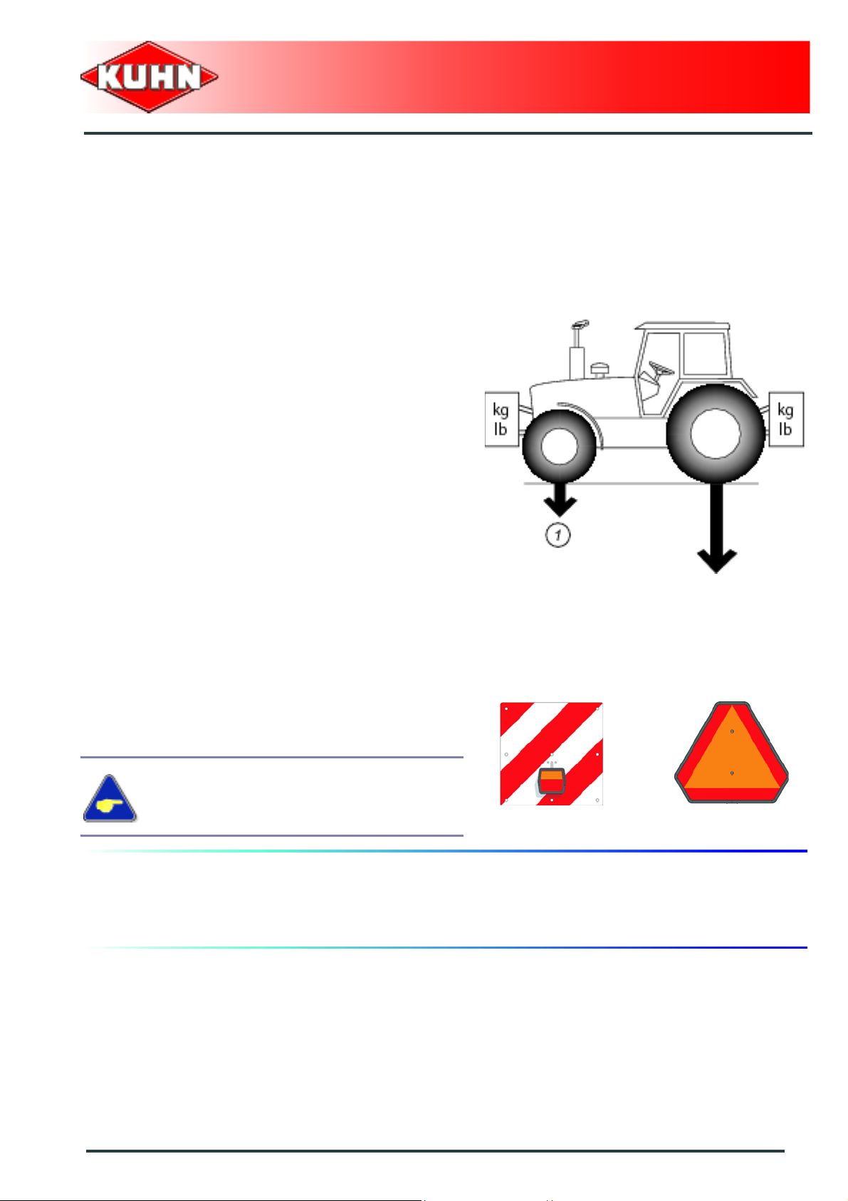
Gross weight and weight per axle
Check that the tractor's authorized gross weigh t as well
as its lift capacity and maximum weight per axle are not
exceeded.
The front axle load (1) must never, under any
circumstances, be less than 20% of the tractor's unladen
weight.
Gyrorake
GA4521GTH
Transport position
Before transporting the machine on public roads, place
the machine into its transport position, according to the
instructions in this manual.
Lights and indicators
Before transporting the machine on public road s, ensure
that all legally required lightings and signallings are in
place.
Ensure that lightings and signallings are clean and in
good working order. Replace any missing or broken
equipment.
Always obey current regulations for driving
on roads.
Maximum speed
Always keep to the legal speed limit for driving a tractormachine assembly on public roads.
Safety
9
Page 12
Precautions when coupling
Before attaching the machine, make sure that it cannot
accidentally start moving (chock the wheels) and that the
parking stand is in the right position.
The machine must only be attached to the hitch points
provided for this purpose.
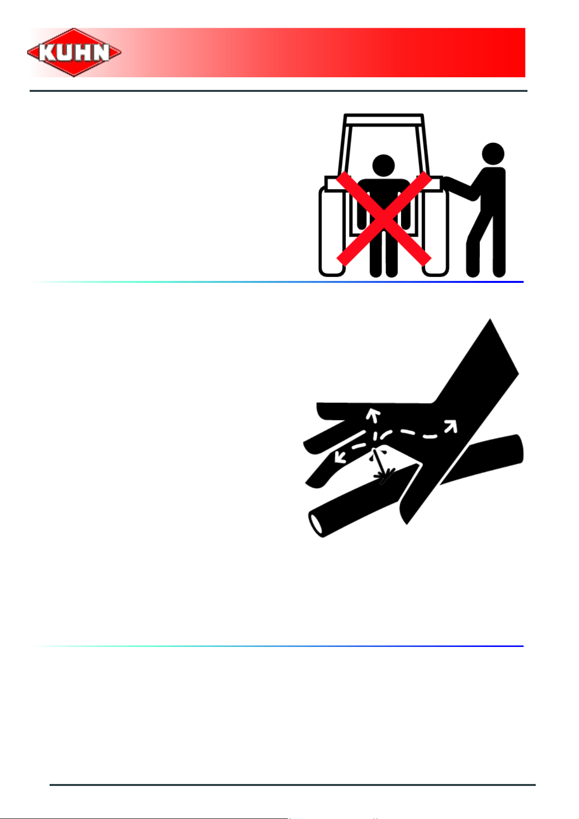
Never stand between the tractor and the machine when
operating the three point linkage.
Do not stand between the tractor and the machine
without ensuring that the parking brake is applied.
Hydraulic circuit
Caution! The hydraulic circuit is under high pressure.
Maximum pressure at work: 200 bar(2900 psi).
Before connecting hoses to the tractor hydraulics,
ensure that tractor and machine circuits are not under
pressure. Before disconnecting a hose, depressurize the
hydraulic circuit.
To avoid making incorrect connections, mark hydraulic
couplers and corresponding hoses with colors.
WARNING! Functions could be reversed (for example:
lift/lower) and cause accidents.
Regularly check the hydraulic hoses. In case of normal
wear, replace the hydraulic hoses every 5 years.
Damaged or worn hoses must immediately be replaced.
When replacing the hydraulic hoses, only use hoses with
the specification recommended by the manufacturer of
the machine.
To locate a leak, use appropr iate means. Protect body
and hands from liquid under pressure.
Any liquid under pressure (particularly oil from
hydraulics) can penetrate the skin and cause severe
injury. If injured, see a doctor immediately, there could
be danger of infection.
Before any adjustments, maintenance or repairs are
carried out, lower the machine on the ground,
depressurize the hydraulics, turn off the engine, remove
ignition key and wait until all moving parts have come to
a complete stop.
Gyrorake
GA4521GTH
10
Safety
Page 13
PTO shaft
Use only PTO shafts supplied with the machine or
recommended by the manufacturer.
The protective shield of the tractor PTO stub, the PTO
shaft guards and the protective covering of the machine
input shaft must always be in place and in good
condition.
Make sure that the PTO shaft guards are se cured with
the safety chains provided.
Any worn or damaged guards must be replaced
immediately. A worn guard or an unprotected PTO shaft
can cause a serious or even a lethal accident.
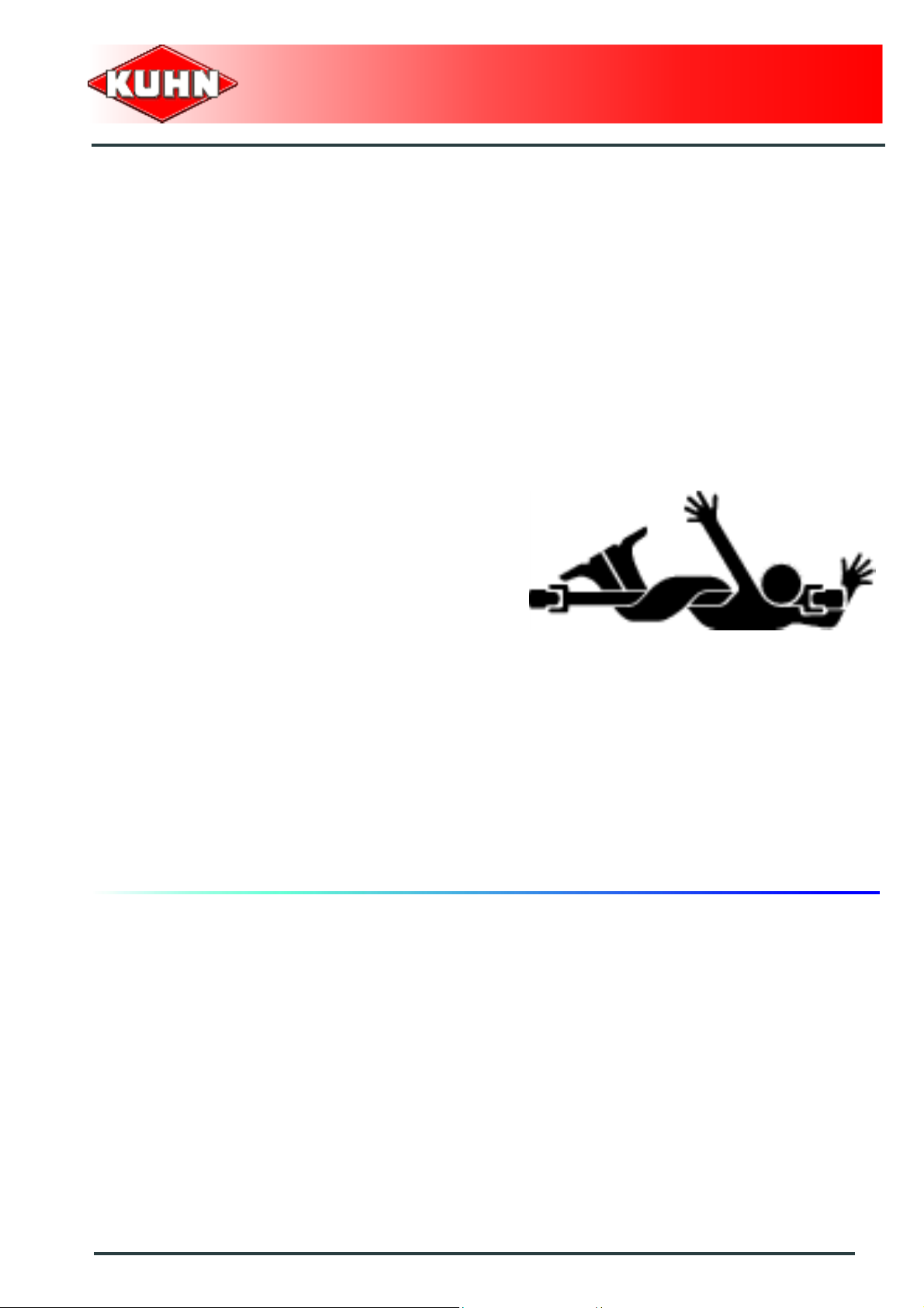
Do not wear loose clothing that could be caught in the
rotating PTO shaft.
Before attaching or removing a PTO shaft, or before
doing any work on the machine, disengage the PTO
drive, turn off the engine, remove ignition key and wait
for all moving parts have come to a complete stop.
If the primary PTO shaft is equipped with a slip clutch or
a free wheel, these must be fitted on the machine side.
Ensure that the PTO shaft is always correctly fitted and
locked into place.
Before connecting the PTO shaft, ensure that the PTO
speed (rotational frequency) and directions of rotation
are in line with manufacturer's recommendations.
Before engaging the PTO drive, make sure all people
and animals are clear from the machine. Never engage
the PTO drive when the tractor engine is stopped.
When uncoupling the machine, rest the PTO shaft on the
support specially provided, and replace protective cover
on the PTO stub of the tractor.
Read and follow the instructions in the operator's ma nual
provided with the PTO shaft.
Gyrorake
GA4521GTH
Safety
11
Page 14
Precautions during manoeuvres
When moving the machine from the transport positio n to
the working position and vice versa, make sure that
nobody is within the machine pivoting area.
Remote controlled components
Danger of crushing and shearing can exist when
components are operated by hydraulic or pneumatic
controls. Keep away from these danger zones.
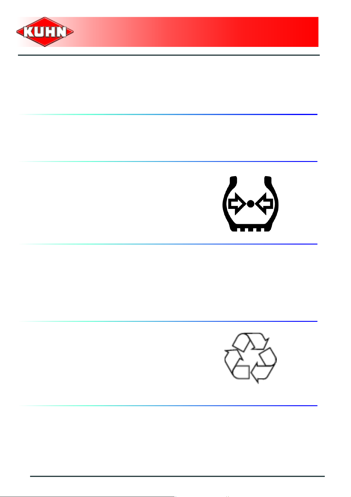
Tyres
Regularly check the tyre pressure. Respect
manufacturers' recommendations on pressure.
Assembly, disassembly and repair of wheels and tyres
must only be carried out by competent persons who are
equipped with standardized tools. Before any work is
performed on the wheels, ensure that the machine rests
on the ground and is perfectly stable so that it cannot
move accidentally (put chocks in place).
Gyrorake
GA4521GTH
Safety decals
Safety warning decals are placed in pictorial form on
various parts of the machine. They are ther e to warn you
of potential dangers and to tell you how to avoid
accidents.
Always keep the safety decals clea n and readable, and
replace them when they are worn, damaged, missing or
illegible.
Waste disposal
Respect the environment! Never spill pollutants (oil,
grease, filters, etc.) on the ground, never pour them
down the drain and never discard them in any other
place where they could pollute the environment. Never
throw away or burn a tyre. Always take waste to
specialized recycling or waste disposal centers.
12
Safety
Page 15
Precautions for maintenance and repair work
Before leaving the tractor or before adjusting,
maintaining or repairing the machine, disengage the
PTO drive, turn off the engine, remove ignition key and
wait until all moving parts have come to a complete stop
and apply park brake.
Rest the machine on the ground, release the pressure
from the hydraulic circuit and leave the machine to cool
down.
Make sure that the parts of the machine that need to be
lifted for maintenance or repair work are firmly propped
up.
Before any work is done on the electric circuit or before
any electric welding is carried out on the attached
machine, disconnect the machine from the tractor
electrical circuit. Also disconnect alternator and battery
terminals.
Repairs on elements under pressure or tension (springs,
pressure accumulators, etc.) must only be carried out by
competent persons with regulation equipment.
Wear the appropriate protective clothing for the work in
hand (gloves, shoes, goggles, helmet, ear defenders,
etc.).
Do not solder, weld or use a blow torch near fluids under
pressure or inflammable products.
For your own safety and for correct machine operation,
only use original manufacturer parts.
It is strongly recommended to have your machine
checked by your Kuhn dealer after each season,
especially tools and their attaching hardware.
Gyrorake
GA4521GTH
Projection of stones and foreign objects
For driver safety, always use a tractor equipped with a
cab. Never start a gyrorake when there are people
nearby. Even when the machine is used in accordance
with its purpose, objects may be projected. Stones and
other foreign objects projected by the moving parts can
travel a considerable distance. Keep all persons and
animals away from the danger zone.
Safety
13
Page 16

Precautions for machine use
Before using the machine, check tools ( tines) and their
attachment hardware in accordance with the instructions
of the present manual.
Check the guards regularly. Immediately replace any
damaged or missing elements.
Before engaging the pto drive, lower the rotors onto the
ground. Make sure all the guards are in place. Keep all
persons and animals away from the danger zone.
Stay a safe distance from the Gyrorake when rotors are
moving.
Never reverse while raking.
After the power source has stopped, the rotors can
continue turning for a time. Stay away from the machine
until all moving parts have come to a complete standstill.
If an obstacle is hit, disengage the PTO drive, stop the
tractor engine, remove the ignition key and wait for all
moving parts to come to a complete standstill. Check the
entire machine for any damage before resuming work.
Gyrorake
GA4521GTH
14
Safety
Page 17

3. Location and description of safety decals on the machine
Location of safety decals
Gyrorake
GA4521GTH
Safety
15
Page 18
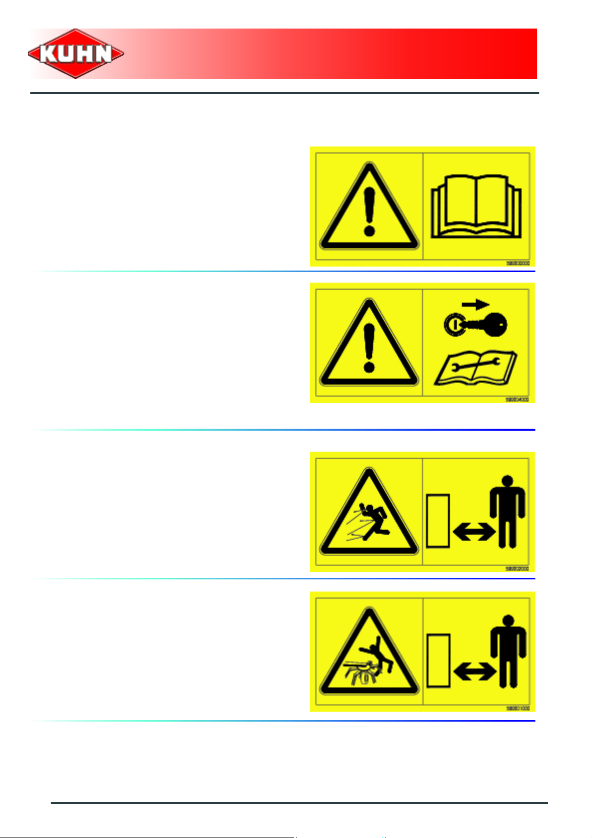
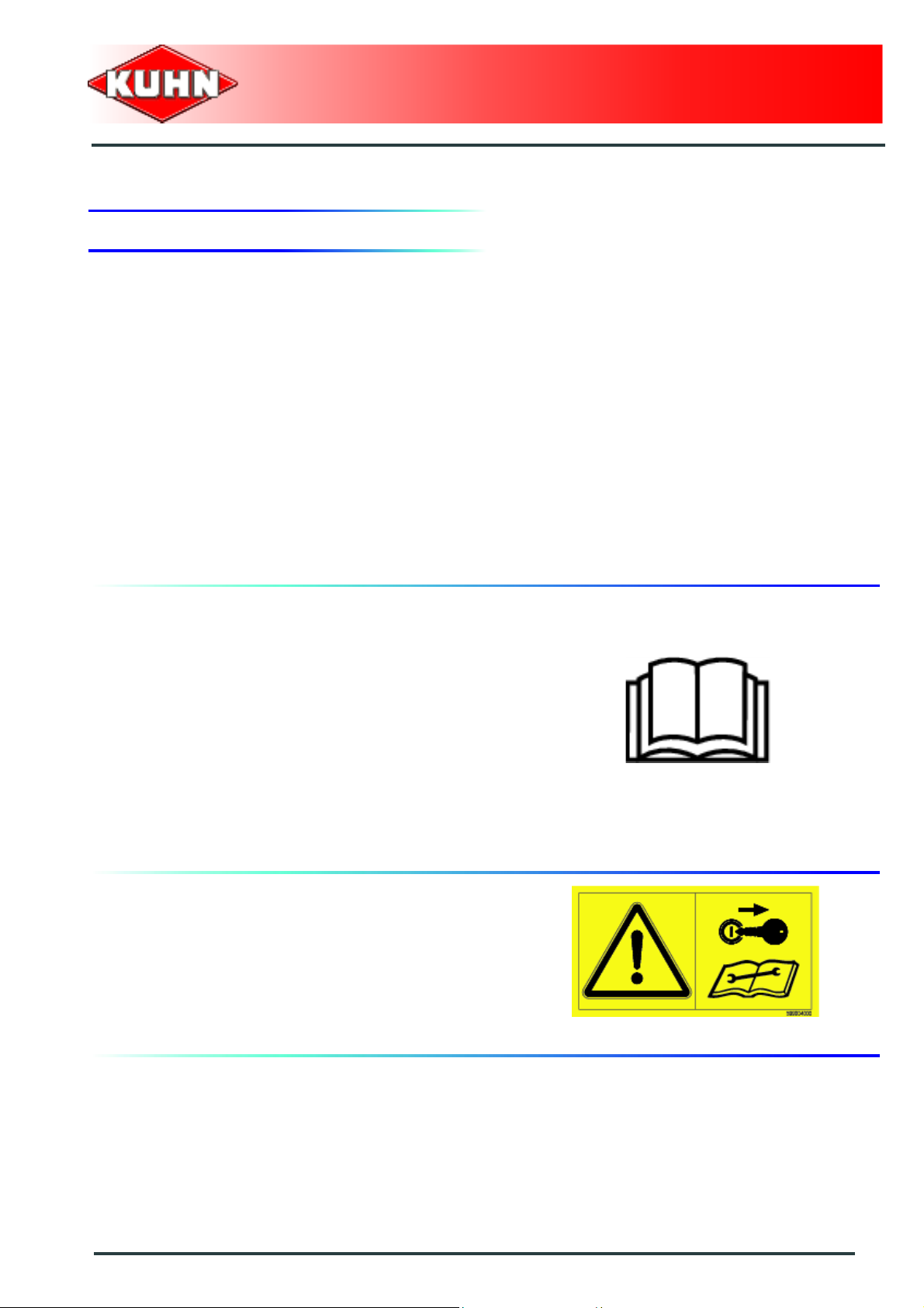
Description of safety decals
Operating instructions (1)
The operators' manual contains all the information
necessary for using the machine safely. It is imperative
to read and comply with all instructions.
Working on the machine (2)
Before leaving the tractor or before adjusting,
maintaining or repairing the machine, disengage the
PTO drive, turn off the engine, remove ignition key and
wait until all moving parts have come to a complete stop
and apply park brake.
Gyrorake
GA4521GTH
Projections (3)
Stones and other debris pro jected by the moving parts
can travel a long distance. Always stay at a safe distance
from the machine.
Rotary tools (4)
To prevent entanglement keep a safe distance from the
machine.
16
Safety
Page 19

Power take-off (5)
When guards are in transport position, the rotor is
locked. Do not engage the PTO drive.
Gyrorake
GA4521GTH
Safety
17
Page 20

4. Road safety equipment and recommendations
The road safety equipment is mounted in the factory or
by your authorized Kuhn dealer according to current
safety regulations. Always keep to the legal speed limit
for driving a tractor-machine assembly on public roads.
Whatever the speed, we recommend, for everyones'
safety, not to exceed a maximum speed of
25 km/h (15.5 mph).
The rear safety device comprises:
- 2 reflective pannels (1).
- 2 signalling lights (2) (red light / stop light / turn signal
light).
- 2 red reflectors (3).
Gyrorake
GA4521GTH
The side device comprises:
- 1 amber reflector (1) on each machine side.
18
Safety
Page 21

$Machine specifications
1. Description and glossary
0
Gyrorake
GA4521GTH
1 : Drawbar 2 : Parking stand
3 : Rotor undercarriage and wheels 4 : Rotor
5 : Tine arms 6 : Swath screen
7 : Tine arm rack 8 : Pitch angle adjustment handle
Machine specifications
19
Page 22

GA4521GTH
2. Technical specifications
GA4521GTH
Attachment type Drawbar coupled to the tractor hitch bar
Number of rotors 1
Rotor diameter 3.65 m (11’11’’)
Number of arms per rotor 13
Number of tines per arm 4
Swath width 1.4 m (4’7’’) approximately
Working width (DIN 11220) up to 4.50 m (14’9’’)
Length in working position 4.15 m (13’7")
Gyrorake
Height in working position 1.30 m (4’3’’)
Width in transport position 2.20 m (7’3’’)
Length in transport position 3.43 m (11’3’’)
Height in transport position 2.37 m (7’9")
Power requirement 26 kW (35 hp)
PTO speed (max.) 540 min
Weight 815 kg (1796 lb)
Tyres 18 / 8.50-8
Tyre pressure 2 bar (29 psi)
-1
3. Sound levels
Sound levels have been measured in accordance with the measuring methods as defined in:
NF EN 1553 "Agricultural machinery - Self-propelled, mounted, semi-mounted and trailed - Common
safety recommendations".
Weighted equivalent continuous acoustic pressure level at the driver's seat (closed cabin) L (A) eq:
Tractor only: 72.8 dB(A).
Tractor + machine: 73.9 dB(A).
20
Machine specifications
Page 23

$Putting into service
1. Coupling and uncoupling
Description of coupling elements
- A PTO shaft 1 3/8’’ 6 splines.
- An electric 7-pin plug for the signalling equipment.
- A parking stand.
- 1 hydraulic hose with a 2 position shut-off valve
pressurizing the machine transport/work position
cylinder.
- 2 hydraulic hoses pressurizing the windrow curtain
setting cylinder (depending upon specification).
Gyrorake
GA4521GTH
Preparing the tractor
The machine adapts to tractors fitted with a pull bar.
The tractor nominal PTO speed must be 540 min
The tractor must be equipped with :
- 1 single acting hydraulic outlet.
- 1 double acting hydraulic outlet (depending upon
specification).
-1
.
Putting into service
21
Page 24

Drawbar height adjustment
- Turn parking stand crank to bring the drawbar in line
with the tractor's pullbar.
Gyrorake
GA4521GTH
Coupling the machine
- Couple machine to tractor and secure hitch pin (1).
- Raise parking stand (1) using crank (2).
- Remove specific pin (3).
(Pin with automatic locking mechanism).
- Remove and store parking stand in its holder.
- Lock parking stand using specific pin (3).
22
Putting into service
When optional equipment is used, follow specific
procedures mentioned in the related section:
- Safety chain.
- Prop wheel.
- Hydraulic windrow curtain.
Page 25

Hydraulic connection
- Connect hydraulic hose to a single acting spool valve.
Position a: Circuit open.
Position b: Circuit closed.
Gyrorake
GA4521GTH
When optional equipment is used, follow specific
procedures mentioned in the related section:
- Hydraulic windrow curtain.
Electrical connections
Connect 7-pin plug to the tractor.
Putting into service
23
Page 26

Primary PTO shaft
Make sure that the PTO shaft is correctly
adjusted, to avoid premature wear and tear.
The tractor nominal PTO speed must be 540 min-1.
Separate the two half PTO shafts and connect them to
the machine's input shaft and to the tractor PTO stub.
Check the length of the PTO shaft:
- When the PTO shaft is in its maximum overlap
position (retracted), tubes should not butt against the
yokes. As a safety measure, a clearance (L) of at least
25 mm (1’’) must be maintained.
- When the PTO shaft is in its maximum extended
position, the tube overlap must be more than
250 mm (10’’).
Gyrorake
GA4521GTH
If this is not the case:
- Mark length (H) to cut when the transmission is the
maximum overlap position.
- Shorten the guard tubes and the transmission tubes
by the same length.
- Bevel and clean the tubes.
- Grease the inside of the outer tube.
Check that there is still a minimum overlap of
250 mm (10’’) when the machine is in working
position and the tractor in line with the machine.
Never operate the PTO shaft at an angle X exceeding
30°.
24
Putting into service
Page 27

To avoid serious accidents, the PTO drive
shaft guards must be properly in place and
fixed with the chains provided.
Attach PTO shaft guard chain in hole (1) on machine
side.
Immediately replace any worn or damaged
guard.
Gyrorake
GA4521GTH
Lower PTO shaft support (2).
Putting into service
25
Page 28

Uncoupling the machine
Park the machine on an even fairly level
ground.
Uncouple the machine in work or transport
position.
From the transport position:
- Open hydraulic hose valve of the cylinder setting the
transport/work position.
Position a: Circuit open.
Position b: Circuit closed.
- Lower machine until undercarriage is fully retracted.
Gyrorake
GA4521GTH
- Raise PTO shaft support (1).
- Disconnect the PTO shaft from the tractor.
- Secure PTO shaft into its' support (1).
- Disconnect and store hydraulic hose on machine.
- Disconnect and store signalling equipment plug in its
holder (2).
26
Putting into service
Page 29

- Remove specific pin (3).
(Pin with automatic locking mechanism).
- Install parking stand (1) on drawbar.
- Lock parking stand using specific pin.
- Adjust parking stand height using crank handle (2).
When optional equipment is used, follow specific
procedures mentioned in the related section :
- Safety chain.
- Remove pin (1).
Gyrorake
GA4521GTH
The machine is uncoupled.
Putting into service
27
Page 30

$Instructions for transport
1. Putting the machine into transport
Before placing the machine into transport
position:
- Wait until the rotating parts have come
to a complete stop.
- Check that nobody is within the machine
pivoting area.
- If there is someone, make sure the
person moves away.
Gyrorake
GA4521GTH
position
When optional equipment is used, follow specific
procedures mentioned in the related section:
- Prop wheel.
- Hydraulic windrow curtain.
From the working position:
- Release windrow curtain lock (1).
- Push windrow curtain (2) towards the machine in side.
- Lower lock (1) to lock windrow curtain.
28
Instructions for transport
Page 31

Before folding side guards:
- Rotate rotor by hand until non-disconnectable tine
arms are positioned to the front on each side of the
beam.
- Pull on handles (2) to unlock the side guards.
- Fold and lock guards (1).
Gyrorake
GA4521GTH
The folding of the side guards activates the rotor
pre-locking by means of link rods (2).
- Rotate rotor by hand until fully locked with rotor lock
(1)
.
Check that rotor lock (1) is fully engaged.
The rotor must no longer rotate.
Instructions for transport
29
Page 32

- Remove lynch pins (1).
- Disconnect tine arms (2).
Gyrorake
GA4521GTH
3 non disconnectable tine arms (1) are not
removed.
- Position tine arms (2) on racks (3).
- Secure tine arms with lynch pins.
30
Instructions for transport
Page 33

- Activate tractor single acting valve to fully raise the
machine.
- Shut-off hydraulic hose valve of cylinder setting the
machine in transport/work position.
Position a: Circuit open.
Position b: Circuit closed.
The machine is in transport position.
Never engage the tractor PTO drive when t he
machine is in transport position.
Gyrorake
GA4521GTH
2. Conformity with the road regulations
Before driving the machine on public roads,
ensure that the machine complies with
current highway code regulations.
Always keep to the legal speed limit for driving a tractormachine assembly on public roads.
- Check that the retroreflective signalling equipment is
clean and that the lighting equipment functio ns before
going on public roads.
Immediately replace any damaged or missing
elements.
Instructions for transport
31
Page 34

$Instructions for work
Before placing the machine in working
position:
- Check that nobody is within the machine
pivoting area.
- If there is someone, make sure the
person moves away.
1. Putting the machine into work position
Gyrorake
GA4521GTH
When optional equipment is used, follow specific
procedures mentioned in the related section:
- Prop wheel.
- Hydraulic windrow curtain.
From the transport position:
- Remove lynch pin from tine arms stor ed on rack s.
- Fit tine arms on the rotor.
- Insert and lock lynch pin (1).
Position a: Circuit open.
Position b: Circuit closed.
- Open hydraulic hose valve of the cylinder setting the
transport/work position.
- Activate the transport/work cylinder control valve in
the "pivot into work" position.
- Lower machine until undercarriage is fully retracted.
- Pull on handles (2) to unlock the side guards.
- Unfold and lock guards (1).
32
Instructions for work
Page 35

- Release windrow curtain lock (1).
- Position windrow curtain (2) towards the machine
outside.
Gyrorake
GA4521GTH
- Lower lock (1) to lock windrow curtain.
The machine is in working position.
Instructions for work
33
Page 36

.
2. Adjustments in working position
Before manoeuvring the machine:
- Check that nobody is within the machine
pivoting area.
- If there is someone, make sure the
person moves away.
- Activate single acting valve to lower the machine until
the tines slightly skim the ground.
- Fully turn undercarriage crank.
Gyrorake
GA4521GTH
- Refine the rotor levelling with crank handle.
The adjustment is correct when :
- Tines slightly skim the ground.
- Tine arms are level.
34
Instructions for work
Page 37

Windrow curtain adjustment
There are 3 windrow curtain adjustment possibilities.
When optional equipment is used, follow specific
procedures mentioned in the related section:
- Hydraulic windrow curtain.
Swath width adjustment:
- Release windrow curtain lock (1).
- Adjust windrow curtain position.
- Position lock (1) in one of the holes (3) corresponding
to the required windrow width.
- Lower lock (1) to lock windrow curtain.
In very dense forage, increase d istance betwe en
windrow curtain and rotor.
Gyrorake
GA4521GTH
- In very dense crop, the machine can form single
swaths.
- In light crop, the machine can form double swaths.
Instructions for work
35
Page 38

Vertical adjustment:
The windrow curtain can be adjusted in different
positions:
- High position.
- Central position.
- Low position.
• The upper position is used in very ir re gular g round s
or in very dense crop.
• The low position is used in low density crop
In most cases, position windrow curtain in the
central position.
.
Gyrorake
GA4521GTH
Lengthways adjustment:
The windrow curtain can be set forwards or backwards
according to the crop density and the windrow width
adjustment.
The forward position can be used for green
forage and narrow windrows.
To adjust the windrow curtain:
- Remove bolts (1).
- Adjust swath screen position.
- Reinstall bolts (1).
• Torque: 4.9 daN m (37 lbf ft).
36
Instructions for work
Page 39

3. Machine use
Before engaging the tractor PTO drive:
- Keep all persons and animals away from
the machine danger zone.
- Lower and lock side guards.
- Place the machine in working position.
Before the machine engages the crop:
- Engage the tractor PTO drive and accelerate
progressively up to the desired PTO speed.
Gyrorake
GA4521GTH
The tractor PTO stub must rotate at a speed
of 540 min
Determine groundspeed/engine speed ratio that
is best suited to the work conditions.
Groundspeed
Groundspeed must be adapted to the encountered
working conditions.
Reduce groundspeed in difficult working
conditions.
-1
.
Do not use foot throttle.
Instructions for work
37
Page 40

1. Safety chain
Kit no. 1116860.
The safety chain is intended to keep the
machine under control in the event of a loss
or failure of the hitch pin.
Gyrorake
GA4521GTH
$Optional equipment
Coupling the machine
- Couple machine to tractor and secure hitch pin (1).
- Raise parking stand (1) using crank (2).
- Remove specific pin (3).
(Pin with automatic locking mechanism).
- Remove and store parking stand in its holder.
- Lock parking stand using specific pin (3).
38
Optional equipment
Page 41

The safety chain must be tied around a tractor
attachment point other than the attachment bar.
Gyrorake
GA4521GTH
Optional equipment
39
Page 42

2. Prop wheel
Kit no. 1146600
The prop wheel provides better adaptation to irregular
ground contours.
The prop wheel can be fitted either on the right or left
side of the front frame.
Machine use
- Place the machine in working position.
- Lower the prop wheel using handle (1) until it touches
the ground.
- Give a few additional hand le turns to ensure that th e
additional support wheel is always in contact with the
ground.
Gyrorake
GA4521GTH
Lubrication
Every 50 hours
Grease:
- Pivot points (2).
40
Optional equipment
Page 43

3. Hydraulic windrow curtain
Kit no. 1136420
This equipment allows windrow width adjustment as
from the tractor cabin.
Preparing the tractor
The tractor must be equipped with :
- 1 double acting hydraulic outlet.
Gyrorake
GA4521GTH
Hydraulic connection
- Connect hydraulic hoses (1) and (2) to the same
tractor hydraulic double outlet.
Putting the machine into transport position
From the working position:
- Operate the double acting valve to pivot the windrow
curtain towards the machine.
Optional equipment
41
Page 44

Before folding side guards:
- Rotate rotor by hand until non-disconnectable tine
arms are positioned to the front on each side of the
beam.
- Pull on handles (2) to unlock the side guards.
- Fold and lock guards (1).
Gyrorake
GA4521GTH
The folding of the side guards activates the rotor
pre-locking by means of link rods (2).
- Rotate rotor by hand until non-disconnectable tine
arms are positioned to the front on each side of the
beam.
- Rotate rotor by hand until fully locked with rotor lock
(1).
Check that rotor lock (1) is fully engaged.
The rotor must no longer rotate.
42
Optional equipment
Page 45

- Remove lynch pins (1).
- Remove tine arms (2).
Gyrorake
GA4521GTH
3 non disconnectable tine arms (1) are not
removed.
- Position tine arms (2) on racks (3).
- Secure tine arms with lynch pins.
Optional equipment
43
Page 46

- Activate tractor single acting valve to fully raise the
machine.
- Shut-off hydraulic hose valve of cylinder setting the
machine in transport/work position.
Position a: Circuit open.
Position b: Circuit closed.
The machine is in transport position.
Never engage the tractor PTO drive when the
machine is in transport position.
Gyrorake
GA4521GTH
Putting the machine into work position
Before placing the machine in working
position:
- Check that nobody is within the machine
pivoting area.
- If there is someone, make sure the
person moves away.
From the transport position:
- Remove lynch pin from tine arms stor ed on rack s.
- Fit tine arms on the rotor.
- Insert and lock lynch pin (1).
44
Optional equipment
Page 47

- Open hydraulic hose valve of the cylinder setting the
transport/work position.
- Activate the transport/work cylinder control valve in
the "pivot into work" position.
- Lower machine until undercarriage is fully retracted.
Position a: Circuit open.
Position b: Circuit closed.
Gyrorake
GA4521GTH
- Pull on handles (2) to unlock the side guards.
- Unfold and lock guards (1).
Operate the double acting valve to pivot the windrow
curtain in working position.
The machine is in working position.
Optional equipment
45
Page 48

Adjustments:
Swath width adjustment:
The windrow width adjustment and
transport/work position setting are controlled by
the same double acting valve.
With the windrow curtain in raised position:
- Operate the double act ing va lve to p lace the windrow
curtain in required position.
In very dense forage, increase distance between
windrow curtain and rotor.
Gyrorake
GA4521GTH
- In very dense crop, the machine can form single
swaths.
- In light crop, the machine can form double swaths.
46
Optional equipment
Page 49

Vertical adjustment:
The windrow curtain can be adjusted in different
positions:
- High position.
- Central position.
- Low position.
• The upper position is used in very irregular grounds
or in very dense crop.
• The low position is used in low density crop
In most cases, position windrow curtain in the
central position.
.
Lengthways adjustment:
Gyrorake
GA4521GTH
The windrow curtain can be set forwards or backwards
according to the crop density and the windrow width
adjustment.
The forward position can be used for green
forage and narrow windrows.
To adjust the windrow curtain:
- Remove bolts (1).
- Adjust swath screen position.
- Reinstall bolts (1).
• Torque: 4.9 daN m (37 lbf ft).
Maintenance:
Lubricate with SHELL SAE 90 EP (GL4) gear oil.
- Cylinder pins.
Optional equipment
47
Page 50

Before carrying out any maintenance or
repairs on the machine, switch off the trac tor
engine, remove ignition key, wait until all
moving parts have come to a standstill and
apply park brake.
1. Frequency chart
Gyrorake
GA4521GTH
$Maintenance and storage
Maintenance intervals are indicated for
normal conditions of use.
Lubrication
Grease:
- Rotor gears
- Rotor arm housings
- Pivot points
- Removable tine arm ends
- The pitch angle adjustment
handle and its pivot pin
After the first 10
hours of use
Every 50 hours
3
3
3
Every 200 hours
or at the end of
the season
3
3
Maintenance
- Tighten machine screws and
nuts
48
Maintenance and storage
33
Page 51

2. Lubrication
The pictorials show the points to be greased (Part
no. 099054002).
Clean grease nipples before greasing.
Lubricate with SHELL multi-purpose grease
grade NLGI 2.
Lubricate with SHELL SAE 90 EP (GL4) gear oil.
Gyrorake
GA4521GTH
Intermediate PTO shaft
- Every 8 hours:
• U-joints (1).
- Every 20 hours:
• transmission tube (2).
- Every 40 hours:
• guide rings (3).
• locking pins (4).
Rotor
The reduction gearbox is lubricated for life
with 1.3 kg (2.9 lb) of multi-purpose semi-fluid
grease SHELL grade NLGI 0.
The guiding cam is lubricated for life with SHELL
multi-purpose grease grade NLGI 2.
Maintenance and storage
49
Page 52

Lubricate the following parts:
Lubricate with SHELL multi-purpose grease
grade NLGI 2.
Grease:
Lubrication intervals are indicated for normal
conditions of use.
- Rotor gears (1).
Gyrorake
GA4521GTH
- Rotor arm housings (1).
In difficult or intensive work conditions,
reduce greasing intervals of rotor arm
housings.
- Undercarriage:
• Pivot points.
• Swinging arms (1).
50
Maintenance and storage
Page 53

- Clean and grease removable tine arm ends (1) with
never-seize grease each time it becomes difficult to
disconnect them.
Gyrorake
GA4521GTH
- The pitch angle adjustment handle and its pivot pin.
Maintenance and storage
51
Page 54

3. Maintenance
Check thighteness of all bolts and nuts, particularly on
rotors.
Gyrorake
GA4521GTH
4. Storage
At the end of each season
Avoid high pressure water jets on rotor and
pivot points.
- Clean the machine thoroughly.
- Put the machine under cover in a dry place.
- Check that all nuts and bolts are sufficiently tightened.
- Lubricate all grease points.
- Clean and pack the connections betw een rotor arms
and removable tine arms with never-seize grease.
- Check good sealing:
• Of the reduction gearbox.
• Rotors.
- Check the condition of the hydraulic hoses.
- Touch up any areas of damaged paintwork.
At the start of each season
- Re-read the operators' manual.
- Check tyre pressure:
• Rotor wheels: 2 bar (29 psi).
- Check that the lighting system (bulb) functions
properly.
- Make sure that all protection devices are in place and
in good condition.
52
Maintenance and storage
Page 55

$Trouble shooting guide
Problem Cause Remedy
Poor raking over the whole
rotor width
Poor raking on one side of
the rotor
Poor raking on the two sides Rotor tilted frontward Adjust drawbar cylinder
Poor raking in the middle Rotor tilted rearwards Shorten the top link
Crop pick up at the rear of
the rotor
Crop ejection at the front of
the swath screen
Crop ejection underneath the
swath screen
Torque limiter disengages
frequently
Unusual rotor vibrations Rotor speed too high
Tines too far from the ground Adjust wheel height
Rotor tilted towards the opposite
side
Swaths too compact between
tines and swath screen
Earth clods on tines Adjust wheel height
Rotor speed too high Reduce PTO speed
Incorrect swath screen position:
Too much at the rear
Incorrect swath screen position:
Too far away from the ground
Load on tine arms is too high
Adjust wheel height to obtain
same tine/soil distance on both
machine sides
Increase swath screen distance
Move swath screen forwards
Reduce PTO speed
Move swath screen downwards
Adjust wheel height
Reduce ground speed
Check PTO speed:
(540 min
-1
max.)
Gyrorake
GA4521GTH
Trouble shooting guide
53
Page 56

$Limited warranty
Gyrorake
GA4521GTH
54
Limited warranty
Page 57

Gyrorake
GA4521GTH
Limited warranty
55
Page 58

Page 59

Page 60

 Loading...